EP2980913A1 - Battery module - Google Patents
Battery module Download PDFInfo
- Publication number
- EP2980913A1 EP2980913A1 EP13880311.9A EP13880311A EP2980913A1 EP 2980913 A1 EP2980913 A1 EP 2980913A1 EP 13880311 A EP13880311 A EP 13880311A EP 2980913 A1 EP2980913 A1 EP 2980913A1
- Authority
- EP
- European Patent Office
- Prior art keywords
- battery
- battery module
- cooling
- blocks
- unit batteries
- Prior art date
- Legal status (The legal status is an assumption and is not a legal conclusion. Google has not performed a legal analysis and makes no representation as to the accuracy of the status listed.)
- Ceased
Links
Images







Classifications
-
- H—ELECTRICITY
- H01—ELECTRIC ELEMENTS
- H01M—PROCESSES OR MEANS, e.g. BATTERIES, FOR THE DIRECT CONVERSION OF CHEMICAL ENERGY INTO ELECTRICAL ENERGY
- H01M10/00—Secondary cells; Manufacture thereof
- H01M10/60—Heating or cooling; Temperature control
- H01M10/62—Heating or cooling; Temperature control specially adapted for specific applications
- H01M10/625—Vehicles
-
- B—PERFORMING OPERATIONS; TRANSPORTING
- B60—VEHICLES IN GENERAL
- B60L—PROPULSION OF ELECTRICALLY-PROPELLED VEHICLES; SUPPLYING ELECTRIC POWER FOR AUXILIARY EQUIPMENT OF ELECTRICALLY-PROPELLED VEHICLES; ELECTRODYNAMIC BRAKE SYSTEMS FOR VEHICLES IN GENERAL; MAGNETIC SUSPENSION OR LEVITATION FOR VEHICLES; MONITORING OPERATING VARIABLES OF ELECTRICALLY-PROPELLED VEHICLES; ELECTRIC SAFETY DEVICES FOR ELECTRICALLY-PROPELLED VEHICLES
- B60L50/00—Electric propulsion with power supplied within the vehicle
- B60L50/50—Electric propulsion with power supplied within the vehicle using propulsion power supplied by batteries or fuel cells
- B60L50/60—Electric propulsion with power supplied within the vehicle using propulsion power supplied by batteries or fuel cells using power supplied by batteries
- B60L50/64—Constructional details of batteries specially adapted for electric vehicles
-
- H—ELECTRICITY
- H01—ELECTRIC ELEMENTS
- H01M—PROCESSES OR MEANS, e.g. BATTERIES, FOR THE DIRECT CONVERSION OF CHEMICAL ENERGY INTO ELECTRICAL ENERGY
- H01M10/00—Secondary cells; Manufacture thereof
- H01M10/60—Heating or cooling; Temperature control
- H01M10/61—Types of temperature control
- H01M10/613—Cooling or keeping cold
-
- H—ELECTRICITY
- H01—ELECTRIC ELEMENTS
- H01M—PROCESSES OR MEANS, e.g. BATTERIES, FOR THE DIRECT CONVERSION OF CHEMICAL ENERGY INTO ELECTRICAL ENERGY
- H01M10/00—Secondary cells; Manufacture thereof
- H01M10/60—Heating or cooling; Temperature control
- H01M10/65—Means for temperature control structurally associated with the cells
- H01M10/655—Solid structures for heat exchange or heat conduction
- H01M10/6554—Rods or plates
-
- H—ELECTRICITY
- H01—ELECTRIC ELEMENTS
- H01M—PROCESSES OR MEANS, e.g. BATTERIES, FOR THE DIRECT CONVERSION OF CHEMICAL ENERGY INTO ELECTRICAL ENERGY
- H01M10/00—Secondary cells; Manufacture thereof
- H01M10/60—Heating or cooling; Temperature control
- H01M10/65—Means for temperature control structurally associated with the cells
- H01M10/655—Solid structures for heat exchange or heat conduction
- H01M10/6556—Solid parts with flow channel passages or pipes for heat exchange
-
- H—ELECTRICITY
- H01—ELECTRIC ELEMENTS
- H01M—PROCESSES OR MEANS, e.g. BATTERIES, FOR THE DIRECT CONVERSION OF CHEMICAL ENERGY INTO ELECTRICAL ENERGY
- H01M10/00—Secondary cells; Manufacture thereof
- H01M10/60—Heating or cooling; Temperature control
- H01M10/65—Means for temperature control structurally associated with the cells
- H01M10/656—Means for temperature control structurally associated with the cells characterised by the type of heat-exchange fluid
- H01M10/6567—Liquids
-
- H—ELECTRICITY
- H01—ELECTRIC ELEMENTS
- H01M—PROCESSES OR MEANS, e.g. BATTERIES, FOR THE DIRECT CONVERSION OF CHEMICAL ENERGY INTO ELECTRICAL ENERGY
- H01M50/00—Constructional details or processes of manufacture of the non-active parts of electrochemical cells other than fuel cells, e.g. hybrid cells
- H01M50/20—Mountings; Secondary casings or frames; Racks, modules or packs; Suspension devices; Shock absorbers; Transport or carrying devices; Holders
- H01M50/204—Racks, modules or packs for multiple batteries or multiple cells
- H01M50/207—Racks, modules or packs for multiple batteries or multiple cells characterised by their shape
- H01M50/209—Racks, modules or packs for multiple batteries or multiple cells characterised by their shape adapted for prismatic or rectangular cells
-
- H—ELECTRICITY
- H01—ELECTRIC ELEMENTS
- H01M—PROCESSES OR MEANS, e.g. BATTERIES, FOR THE DIRECT CONVERSION OF CHEMICAL ENERGY INTO ELECTRICAL ENERGY
- H01M50/00—Constructional details or processes of manufacture of the non-active parts of electrochemical cells other than fuel cells, e.g. hybrid cells
- H01M50/20—Mountings; Secondary casings or frames; Racks, modules or packs; Suspension devices; Shock absorbers; Transport or carrying devices; Holders
- H01M50/233—Mountings; Secondary casings or frames; Racks, modules or packs; Suspension devices; Shock absorbers; Transport or carrying devices; Holders characterised by physical properties of casings or racks, e.g. dimensions
- H01M50/24—Mountings; Secondary casings or frames; Racks, modules or packs; Suspension devices; Shock absorbers; Transport or carrying devices; Holders characterised by physical properties of casings or racks, e.g. dimensions adapted for protecting batteries from their environment, e.g. from corrosion
-
- H—ELECTRICITY
- H01—ELECTRIC ELEMENTS
- H01M—PROCESSES OR MEANS, e.g. BATTERIES, FOR THE DIRECT CONVERSION OF CHEMICAL ENERGY INTO ELECTRICAL ENERGY
- H01M50/00—Constructional details or processes of manufacture of the non-active parts of electrochemical cells other than fuel cells, e.g. hybrid cells
- H01M50/20—Mountings; Secondary casings or frames; Racks, modules or packs; Suspension devices; Shock absorbers; Transport or carrying devices; Holders
- H01M50/249—Mountings; Secondary casings or frames; Racks, modules or packs; Suspension devices; Shock absorbers; Transport or carrying devices; Holders specially adapted for aircraft or vehicles, e.g. cars or trains
-
- H—ELECTRICITY
- H01—ELECTRIC ELEMENTS
- H01M—PROCESSES OR MEANS, e.g. BATTERIES, FOR THE DIRECT CONVERSION OF CHEMICAL ENERGY INTO ELECTRICAL ENERGY
- H01M2220/00—Batteries for particular applications
- H01M2220/20—Batteries in motive systems, e.g. vehicle, ship, plane
-
- Y—GENERAL TAGGING OF NEW TECHNOLOGICAL DEVELOPMENTS; GENERAL TAGGING OF CROSS-SECTIONAL TECHNOLOGIES SPANNING OVER SEVERAL SECTIONS OF THE IPC; TECHNICAL SUBJECTS COVERED BY FORMER USPC CROSS-REFERENCE ART COLLECTIONS [XRACs] AND DIGESTS
- Y02—TECHNOLOGIES OR APPLICATIONS FOR MITIGATION OR ADAPTATION AGAINST CLIMATE CHANGE
- Y02E—REDUCTION OF GREENHOUSE GAS [GHG] EMISSIONS, RELATED TO ENERGY GENERATION, TRANSMISSION OR DISTRIBUTION
- Y02E60/00—Enabling technologies; Technologies with a potential or indirect contribution to GHG emissions mitigation
- Y02E60/10—Energy storage using batteries
Definitions
- the present invention relates to a battery module including a plurality of battery blocks in which a plurality of battery cells are arranged and connected.
- the recent battery modules for vehicles including battery blocks in which a number of unit batteries are arranged generate large amounts of heat due to extremely large charge/discharge currents.
- a cooling plate including a refrigerant flow passageway is disposed in a thermally coupled state with the plurality of unit batteries, and refrigerant is supplied to the cooling plate so as to cool the unit batteries (see Patent Literature 1, for example).
- Patent Literature 1 JP 2010-277863 A
- the presence of the coupling components in the battery module may lead to leakage of the refrigerant at a position relatively close to the unit batteries in case of application of shock and the like.
- problems such as short-circuit of the unit batteries or their heating and the like may be caused.
- the present invention was made in view of the above problems, and an object of the invention is to provide a battery module capable of preventing leakage of refrigerant and the like in the module while achieving a decrease in the size of the module as a whole.
- a battery module including a plurality of battery blocks having a predetermined unit battery arrangement and provided with a cooling plate which is disposed, in a thermally coupled state with respect to a plurality of unit batteries, on the opposite side from the electrode surface of the unit batteries, wherein a cooling pipe is endlessly formed from a refrigerant entry to exit so as to be in a thermally coupled state with respect to the cooling plate of the plurality of battery blocks.
- the cooling plate is provided with a groove for fitting the cooling pipe, and the cooling pipe is configured to be detachable from the cooling plate.
- the components for coupling the cooling pipes are reduced, whereby the interval between a plurality of battery blocks can be decreased.
- the size of the battery module can be decreased while employing a plurality of battery blocks.
- the cooling pipe is endlessly formed from the refrigerant entry to exit, whereby the problem of potential refrigerant leakage from the coupling components within the battery module can be solved.
- the number of unit batteries can be increased while ensuring battery module assembly workability and the dimensional accuracy and strength of the components constituting the battery blocks.
- cooling pipe is configured to be detachable from the cooling plate, easy assembly can be ensured even when the length of the cooling pipe is large or its shape is complex, or when the number of battery blocks in thermally coupled state is large.
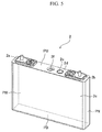
- FIG. 1 is a perspective view of the exterior of a battery block according to the present embodiment.
- FIG. 2 is a perspective view of the battery block of FIG. 1 in a partially exploded state.
- the battery block 1 as illustrated in FIG. 2 , for example, has a configuration in which a plurality of unit batteries 2 are arranged.
- the battery block 1 includes a plurality of spacers 3 individually disposed between the plurality of unit batteries 2, and bridge bars 4 extending along the direction in which the plurality of unit batteries 2 are arranged and engaging the plurality of spacers 3.
- the battery block 1 includes a pair of aluminum-alloy end plates 5 disposed at both ends in the arranged direction of the plurality of unit batteries 2 and thereby sandwiching the unit batteries from both sides in the arranged direction; an aluminum-alloy section plate 6 disposed at an intermediate position in the arranged direction of the plurality of unit batteries 2 and partitioning the plurality of unit batteries 2 into one and the other side in the arranged direction; and a pair of connection plates 7 disposed along both ends in a width direction of the plurality of unit batteries 2 and extending from one end to the other end in the arranged direction, to which connection plates 7 the pair of end plates 5, the section plate 6, and the bridge bars 4 are respectively secured.
- the securing may include fastening screws.
- the top of the unit batteries 2 in a height direction thereof is covered with an insulating cover 8, one on either side of the section plate 6. On top of the insulating cover 8, a substrate unit 9 is disposed.
- the plurality of unit batteries 2 are provided with positive external terminals 2a and negative external terminals 2b which are disposed alternately continuously along the arranged direction, with the positive external terminals 2a and the negative external terminals 2b of the adjacent unit batteries being electrically connected respectively by a plurality of bus bars 10.
- Each of the bus bars 10 is connected to a connection terminal 9a of the substrate unit 9.
- the substrate unit 9 includes a circuit for measuring the voltage of each unit battery 2, a fuse, and the like.
- terminal caps 11 fitted in the insulating cover 8 and covering the terminals of the unit batteries 2.
- the battery block 1 is provided with a cooling plate 12.
- the cooling plate 12 is positioned on the lower side in the battery height direction of the unit batteries 2, and is secured to the end plates 5 and the section plate 6 by fastening screws. Between each of the unit batteries 2 and the cooling plate 12, a heat-conductive sheet 13 is disposed to provide a thermally coupled state coupling the respective unit batteries 2 and the cooling plate 12 in a heat transmissible manner.
- FIG. 3 is a partial cross-sectional view of FIG. 2 illustrating the thermally coupled state of the unit batteries 2 and the cooling plate 12.
- the heat-conductive sheet 13 may include a thermally conductive adhesive as well as a sheet material.
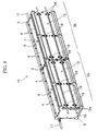
- FIG. 4 is a perspective view of the block 1 as viewed from the cooling plate 12 side.
- the cooling plate 12 includes a thick-plate member of metal having high heat conductivity, such as aluminum alloy, for example.
- the cooling plate 12 extends along the battery arranged direction while facing the bottom surface PB (see FIG. 3 ) of the unit batteries 2.
- the cooling plate 12 has an approximately rectangular flat-plate shape as viewed in plan, with a height approximately the same as the battery width of the unit batteries 2.
- recessed grooves 12a for fitting cooling pipes 18 are recessed.
- the recessed grooves 12a have a shape enabling the fitting of at least a part of the cooling pipes 18.
- the recessed grooves 12a have U-shaped cross section allowing the cooling pipes 18 to be almost entirely fitted in the exposed surface.
- the recessed grooves 12a are parallel with each other at a predetermined interval therebetween in the lateral width direction of the unit batteries 2, while extending between the pair of end plates 5 along the arranged direction of the unit batteries 2.
- recess portions 12b for fitting and screwing cooling-pipe mounting brackets 19.
- the recess portions 12b are disposed at predetermined intervals in the length direction of the recessed grooves 12a.
- the recess portions 12b have a predetermined length in a direction perpendicular to the recessed grooves 12a.
- the cooling plate 12 is cooled by the cooling pipes 18 serving as refrigerant flow passageways.
- the configuration of the cooling pipes 18 will be described later.
- FIG. 5 is a perspective view illustrating a configuration of the unit battery 2.
- the unit batteries 2 are lithium ion secondary batteries all having the same configuration. As illustrated in FIG. 5 , the unit battery 2 is a flat box-shaped rectangular battery including a positive external terminal 2a and a negative external terminal 2b for voltage input and output. The external terminals 2a and 2b are provided with bolts for fastening the bus bars 10, the structure allowing the bus bars 10 to be secured with nuts.
- the unit battery 2 is assembled by putting flat electrodes in a rectangular container 2c, sealing the container with a battery lid 2d, and then injecting nonaqueous electrolyte into the rectangular container 2c via an injection opening 2e in the battery lid 2d.
- the rectangular container 2c has an electrode surface PU provided with the external terminals 2a and 2b; a bottom surface PB having an approximately rectangular shape as viewed in plan and facing the electrode surface PU; a pair of wider side surfaces PW bent from a pair of the long sides of the bottom surface PB and facing each other; and a pair of narrower side surfaces PN bent from a pair of the short sides of the bottom surface PB and facing each other.
- the weight and size of the battery block 1 as a whole can be adjusted by varying the number of the constituent unit batteries 2, while ensuring assembly workability of the battery block 1 and the accuracy and strength of the constituent components.
- FIG. 6 is a perspective view of the exterior of an embodiment of a battery module.
- FIG. 7 is a perspective view of the battery module of FIG. 6 in a partially exploded state.
- the battery module 14 has a structure in which a plurality of the battery blocks 1 of FIG. 1 , specifically two battery blocks 1A and 1B in the present embodiment, are disposed side by side in the arranged direction of the unit batteries 2, with the electrode surface PU side of the unit batteries 2 forming the side surface on one side in a lateral width direction of the battery blocks, and the bottom surface PB side of the unit batteries 2, that is the cooling plate 12 side, forming the side surface on the other side in the lateral width direction of the battery blocks.
- the plurality of battery blocks 1 are disposed linearly along the arranged direction in a posture state such that the electrode surface PU of the unit batteries 2 is positioned laterally on one side in the lateral width direction, with the cooling plate 12 positioned laterally on the other side in the lateral width direction.
- a base bracket 15 On the bottom surface of the battery blocks 1A and 1B, there is disposed a base bracket 15 of such a length as to extend throughout the two battery blocks 1A and 1B.
- the base bracket 15 is secured to the end plates 5 and the section plates 6 of the battery blocks 1A and 1B by fastening screws.
- an inter-block bus bar 16 (see FIG. 7 ) is provided to electrically connect the battery blocks.
- battery input/output lines 17 are connected to the respective battery blocks 1A and 1B.
- the number of the unit batteries 2 can be increased by providing a plurality of battery blocks 1A and 1B, while ensuring the assembly workability and the accuracy and strength of the components through the use of the battery block 1.
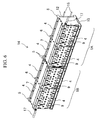
- FIG. 8 is a perspective view of the battery module 14 as viewed from the cooling plate 12 side, which is opposite to the side of FIG. 6 .
- FIG. 9 is a perspective view of the battery module of FIG. 8 in a partially exploded state.
- the first battery block 1A and the second battery block 1B are disposed such that, by being secured on the base bracket 15, the recessed grooves 12a of the respective cooling plates 12 continuously extend linearly. That is, the recessed grooves 12a are disposed linearly along the arranged direction of the unit batteries 2 while spanning the first battery block 1A and the second battery block 1B.
- the cooling pipes 18 are fitted in the recessed grooves 12a of the cooling plates 12a so as to be in a thermally coupled state with respect to the cooling plates 12 of the plurality of battery blocks 1A and 1B.
- the cooling pipes 18 are endlessly continuous, spanning the first battery block 1A and the second battery block 1B.
- the cooling pipes 18 do not have a joint serving as a coupling component between the first battery block 1A and the second battery block 1B, and are instead formed continuously and integrally.
- the location of the cooling pipes 18 is not limited to between the first battery block 1A and the second battery block 1B.
- the pipes may be endlessly continuous while spanning at least two of a plurality of battery blocks. For example, when a third battery block (not shown) is disposed continuously with the second battery block 1B, the pipes may be disposed endlessly continuously while spanning the second battery block 1B and the third battery block 1.
- the cooling pipes 18 are configured to circulate refrigerant using a refrigerant-circulating and heat-exchange device, which is not shown, so as to cool the cooling plates 12.
- the cooling pipes 18 are fitted in the recessed grooves 12a provided in the cooling plates 12, and are secured to the cooling plates 12 with the mounting brackets 19 fitted in the recess portions 12b and by fastening screws.
- the cooling pipes 18 have an outer diameter such that, when secured in the recessed grooves 12a of the cooling plates 12, the outer peripheral surface of the cooling pipes 18 contacts the bottom surface of the recessed grooves 12a having a semi-circular cross section.
- the coupling component for the cooling pipes 18 between the battery blocks 1A and 1B is eliminated, whereby the space for placing the coupling component between the battery blocks 1A and 1B and the space for a coupling work can be omitted. Accordingly, the interval between the battery blocks 1A and 1B can be reduced and the length of the battery module 14 in the arranged direction can be shortened, thereby enabling a decrease in the size of the battery module 14 as a whole.
- the battery blocks 1 constituting the battery module 14 are disposed with the cooling plate 12 facing laterally, and the cooling pipes 18, which are endless while spanning the plurality of battery blocks 1A and 1B, are provided in a detachable manner. Accordingly, the battery module 14 can be easily assembled, maintained, or inspected even when the cooling pipes have a large length or a complex shape, or when the number of the battery blocks 1 in thermally coupled state is large.
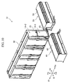
- FIG. 10 is an overall perspective view illustrating an example of mounting of the battery module on a vehicle.
- FIG. 11 illustrates a state of the battery module of FIG. 10 from which the outer cases have been removed.
- an arrow Fr indicates the front of the vehicle; an arrow Re the rear of the vehicle; an arrow V1 the left side in the vehicle width direction; an arrow Vr the right side in the vehicle width direction; an arrow Vu the top of the vehicle; and an arrow Vd the bottom of the vehicle.
- a battery unit 31 is mounted on a vehicle, such as an electric automobile or a hybrid automobile.
- the battery unit 31 includes battery modules 14-1 and 14-2 disposed in a center console of the vehicle; a battery block 41 (second battery block) disposed under the left rear seat of the vehicle; and a battery block 51 (second battery block) disposed under the right rear seat.
- the battery modules 14 and the battery blocks 41, 51 are covered with covers 32, 42, and 52, respectively.
- the battery modules 14-1 and 14-2 include the battery blocks 1A and 1B stacked in upper and lower tiers in a posture state such that the cooling plate 12 side is disposed laterally on the left side V1 in the vehicle width direction.
- the battery module 14-1 configured by the lower-tier battery blocks 1A and 1B and the battery module 14-2 configured by the upper-tier battery blocks 1A and 1B are secured to each other by an intermediate bracket 21 provided therebetween.
- the intermediate bracket 21 is integrally secured to the end plates 5 of the lower-tier battery module 14-1 and the upper-tier battery module 14-2 respectively by fastening screws.
- the recessed grooves 12a in the cooling plates 12 of the battery blocks 1A and 1B extend mutually linearly.
- the recessed grooves 12a in the cooling plates 12 of the battery blocks 1A and 1B extend mutually linearly.
- the recessed grooves 12a in the battery blocks 1A of the lower-tier battery module 14-1 and the upper-tier battery module 14-2 extend parallel to each other while being vertically spaced in each cooling plate 12, and are respectively connected vertically continuously at the forward Fr side end of the vehicle.
- the battery blocks 41 and 51 are disposed along the vehicle width direction V1 - Vr on the rearward Re side of the vehicle with respect to the battery modules 14-1 and 14-2.
- the battery blocks 41 and 51 are disposed facing each other via an interval slightly greater than the lateral width of the battery modules 14-1 and 14-2.
- To the rear of the battery modules 14-1 and 14-2 a predetermined work space portion enclosed on three sides is formed.
- the battery blocks 41 and 51 are secured to the vehicle in a posture state such that the cooling plate 12 side of the battery blocks 1 is disposed on the lower side Vd of the vehicle.
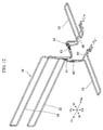
- FIG. 12 is an overall perspective view of the cooling pipes of the battery module illustrated in FIG. 10 .
- FIG. 13 is a perspective view illustrating a first cooling route.
- FIG. 14 is a perspective view illustrating a second cooling route.
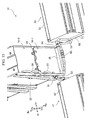
- FIG. 15 is a perspective view illustrating a cooling pipe connection structure.
- the cooling pipes 18 include a cooling pipe 33 passing through the lower-tier battery module 14-1, and a cooling pipe 34 passing through the upper-tier battery module 14-2.
- the lower-tier battery module 14-1 is disposed with the recessed grooves 12a in the cooling plates 12 of the two battery blocks 1A and 1B extending mutually linearly and continuously.
- the cooling pipe 33 is fitted in the recessed grooves 12a of each cooling plate 12 so as to be in a thermally coupled state with respect to the cooling plate 12 of each of the battery blocks 1A and 1B, and is endlessly continuous while spanning the first battery block 1A and the second battery block 1B.
- the cooling pipe 33 does not include a joint serving as a coupling component between the first battery block 1A and the second battery block 1B, and is instead continuously and integrally formed.
- the cooling pipe 33 includes an upstream portion extending from the rear end portion of the second battery block 1B toward the vehicle front Fr in the upper recessed groove 12a of the second battery block 1B, and a downstream portion bent in U shape at the front end portion of the first battery block 1A and extending toward the vehicle rear in the lower recessed groove 12a of the second battery block 1B.
- the cooling pipe 33 is coupled to a cooling pipe 43 of the battery block 41 disposed under the left rear seat of the vehicle.
- the battery block 41 under the left rear seat has generally the same configuration as the battery block 1, with the recessed grooves (not shown) formed in the lower surface of the cooling plate 12 in which the cooling pipe 43 is fit.
- the cooling pipe 43 includes an upstream portion disposed on the vehicle forward side and extending toward the left side V1 in the vehicle width direction, and a downstream portion bent in U shape at the outer position in the vehicle width direction and extending toward the center in the vehicle width direction.
- the upstream portion of the cooling pipe 33 is connected to a refrigerant supply pipe 65 by a joint 61 serving as a coupling means.
- the supply pipe 65 has a proximal end connected to a refrigerant supply opening of a refrigerant-circulating and heat-exchange device, not shown, so as to receive refrigerant supply.
- the downstream portion of the cooling pipe 33 and the upstream portion of the cooling pipe 43 are coupled by a joint 62 serving as a coupling means, so that the refrigerant can flow from the cooling pipe 33 to the cooling pipe 43.
- the downstream portion of the cooling pipe 43 has a proximal end connected to a refrigerant collection opening of the refrigerant-circulating and heat-exchange device, not shown, so as to collect refrigerant.
- the upper-tier battery module 14-2 is disposed with the recessed grooves 12a in the cooling plate 12 of each of the two battery blocks 1A and 1B extending mutually linearly and continuously.
- the cooling pipe 34 is fitted in the recessed grooves 12a of each cooling plate 12 so as to be in a thermally coupled state with respect to the cooling plate 12 of each of the battery blocks 1A and 1B, and is endlessly continuous while spanning the first battery block 1A and the second battery block 1B.
- the cooling pipe 34 does not have a joint serving as a coupling component between the first battery block 1A and the second battery block 1B, and is instead continuously and integrally formed.
- the cooling pipe 34 includes an upstream portion extending from the rear end portion of the second battery block 1B toward the vehicle front Fr in the upper recessed groove 12a of the second battery block 1B, and a downstream portion bent in U shape at the front end portion of the first battery block 1A and extending toward the vehicle rear in the lower recessed groove 12a of the second battery block 1B.
- the cooling pipe 34 is coupled to a cooling pipe 53 of the battery block 51 disposed under the right rear seat of the vehicle.
- the battery block 51 under the right rear seat has generally the same configuration as the battery block 1, with the recessed grooves (not shown) formed in the lower surface of the cooling plate 12 in which the cooling pipe 53 is fit.
- the cooling pipe 53 includes an upstream portion disposed on the vehicle forward side and extending toward the right side Vr in the vehicle width direction, and a downstream portion bent in U shape at the outer position in the vehicle width direction and extending toward the center in the vehicle width direction.
- the upstream portion of the cooling pipe 34 is connected to a refrigerant supply pipe 66 by a joint 63 serving as a coupling means.
- the supply pipe 66 has a proximal end connected to a refrigerant supply opening of the refrigerant-circulating and heat-exchange device, not shown, so as to receive refrigerant supply.
- the downstream portion of the cooling pipe 34 and the upstream portion of the cooling pipe 53 are coupled to each other by a joint 64 serving as a coupling means, so that the refrigerant can flow from the cooling pipe 34 to the cooling pipe 53.
- the downstream portion of the cooling pipe 53 has a proximal end connected to a refrigerant collection opening of the refrigerant-circulating and heat-exchange device, not shown, so as to collect refrigerant.
- the illustrated flow of refrigerant is an example, and the upstream side and the downstream side may be switched.
- the joints 61 and 62 as the coupling means for the cooling pipes 33 and 43, and the joints 63 and 64 as the coupling means for the cooling pipes 34 and 53 are respectively disposed outside the battery modules 14-1 and 14-2 and within a predetermined work space enclosed by the battery modules 14-1 and 14-2 and the battery blocks 41 and 42.
- the length of the battery modules 14-1 and 14-2 in the front-rear direction can be shortened, whereby the size of the battery modules 14-1 and 14-2 as a whole can be decreased.
- the coupling components such as joints are not provided within the battery modules 14-1 and 14-2, the problem of refrigerant leakage, e.g., upon the application of shock can be prevented, thus eliminating the possibility of short-circuit in the unit batteries 2, their heating and the like due to the leaked refrigerant.
- the joints 61 to 64 in the predetermined work area, a work space for joint coupling work can be ensured, allowing the coupling work to be performed easily.
- the coupling components for coupling the cooling pipes 33 and 34 are reduced, whereby the interval between the plurality of battery blocks 1A and 1B can be decreased and the size of the battery modules 14-1 and 14-2 can be reduced while employing a plurality of battery blocks 1.
- the cooling pipes 33 and 34 endlessly formed from the entry to exit of refrigerant, the problem of potential refrigerant leakage from the coupling components in the battery modules 14-1 and 14-2 can be solved.
- the number of the unit batteries can be increased while ensuring the assembly workability of the battery unit 31 and the dimensional accuracy and strength of the components constituting the battery blocks 1A and 1B.
- the battery unit 31 can be easily assembled even when the length of the cooling pipes 33 and 34 is large, their shape is complex, or when the number of the battery blocks 1 in thermally coupled state is large.
Landscapes
- Engineering & Computer Science (AREA)
- Chemical & Material Sciences (AREA)
- Chemical Kinetics & Catalysis (AREA)
- Electrochemistry (AREA)
- General Chemical & Material Sciences (AREA)
- Manufacturing & Machinery (AREA)
- Life Sciences & Earth Sciences (AREA)
- Sustainable Development (AREA)
- Sustainable Energy (AREA)
- Power Engineering (AREA)
- Transportation (AREA)
- Mechanical Engineering (AREA)
- Aviation & Aerospace Engineering (AREA)
- Secondary Cells (AREA)
- Battery Mounting, Suspending (AREA)
Abstract
Description
- The present invention relates to a battery module including a plurality of battery blocks in which a plurality of battery cells are arranged and connected.
- The recent battery modules for vehicles including battery blocks in which a number of unit batteries are arranged generate large amounts of heat due to extremely large charge/discharge currents. As an increase in the temperature of the unit batteries may lead to deterioration in unit battery performance and life, the unit batteries need to be cooled.
- In a method for cooling the unit batteries, a cooling plate including a refrigerant flow passageway is disposed in a thermally coupled state with the plurality of unit batteries, and refrigerant is supplied to the cooling plate so as to cool the unit batteries (see
Patent Literature 1, for example). - Patent Literature 1:
JP 2010-277863 A - In the battery module described in
Patent Literature 1, when a plurality of battery blocks are provided to increase the output voltage, it becomes necessary to couple the cooling pipes, which are refrigerant flow passageways disposed in the respective battery blocks. This results in an increase in the size of the battery module due to the need for leaving a work space and the presence of coupling components. - In addition, the presence of the coupling components in the battery module may lead to leakage of the refrigerant at a position relatively close to the unit batteries in case of application of shock and the like. Depending on the type or leaked amount of the refrigerant, problems such as short-circuit of the unit batteries or their heating and the like may be caused.
- The present invention was made in view of the above problems, and an object of the invention is to provide a battery module capable of preventing leakage of refrigerant and the like in the module while achieving a decrease in the size of the module as a whole.
- The problem is solved by a battery module according to the present invention including a plurality of battery blocks having a predetermined unit battery arrangement and provided with a cooling plate which is disposed, in a thermally coupled state with respect to a plurality of unit batteries, on the opposite side from the electrode surface of the unit batteries, wherein a cooling pipe is endlessly formed from a refrigerant entry to exit so as to be in a thermally coupled state with respect to the cooling plate of the plurality of battery blocks. The cooling plate is provided with a groove for fitting the cooling pipe, and the cooling pipe is configured to be detachable from the cooling plate.
- According to the present invention, the components for coupling the cooling pipes are reduced, whereby the interval between a plurality of battery blocks can be decreased. Thus, the size of the battery module can be decreased while employing a plurality of battery blocks. The cooling pipe is endlessly formed from the refrigerant entry to exit, whereby the problem of potential refrigerant leakage from the coupling components within the battery module can be solved.
- By employing a plurality of battery blocks including a predetermined number of the arrangements, the number of unit batteries can be increased while ensuring battery module assembly workability and the dimensional accuracy and strength of the components constituting the battery blocks.
- Because the cooling pipe is configured to be detachable from the cooling plate, easy assembly can be ensured even when the length of the cooling pipe is large or its shape is complex, or when the number of battery blocks in thermally coupled state is large. Other problems, configurations, and effects will become apparent from the following description of embodiments.
-
-
FIG. 1 is a perspective view of a battery block. -
FIG. 2 is a perspective view of the battery block ofFIG. 1 in a partially exploded state. -
FIG. 3 is a partial cross-sectional view ofFIG. 2 illustrating a thermally coupled state of a unit battery and a cooling plate. -
FIG. 4 is a perspective view of the battery block ofFIG. 1 as viewed from the cooling plate side. -
FIG. 5 is a perspective view of a unit battery. -
FIG. 6 is a perspective view of a battery module according to an embodiment. -
FIG. 7 is a perspective view of the battery module ofFIG. 6 in a partially exploded state. -
FIG. 8 is a perspective view of the battery module ofFIG. 6 as viewed from the cooling plate side. -
FIG. 9 is a partially exploded perspective view of the battery module ofFIG. 8 . -
FIG. 10 is an overall perspective view illustrating an example of mounting of the battery module on a vehicle. -
FIG. 11 illustrates the battery module ofFIG. 10 from which outer cases have been removed. -
FIG. 12 is an overall perspective view of cooling pipes of the battery module ofFIG. 10 . -
FIG. 13 is a perspective view illustrating a first cooling route. -
FIG. 14 is a perspective view illustrating a second cooling route. -
FIG. 15 is a perspective view illustrating a cooling pipe connection structure. - In the following, an embodiment of a battery module according to the present invention will be described with reference to the drawings.
-
FIG. 1 is a perspective view of the exterior of a battery block according to the present embodiment.FIG. 2 is a perspective view of the battery block ofFIG. 1 in a partially exploded state. - The
battery block 1, as illustrated inFIG. 2 , for example, has a configuration in which a plurality ofunit batteries 2 are arranged. Thebattery block 1 includes a plurality ofspacers 3 individually disposed between the plurality ofunit batteries 2, andbridge bars 4 extending along the direction in which the plurality ofunit batteries 2 are arranged and engaging the plurality ofspacers 3. - The
battery block 1 includes a pair of aluminum-alloy end plates 5 disposed at both ends in the arranged direction of the plurality ofunit batteries 2 and thereby sandwiching the unit batteries from both sides in the arranged direction; an aluminum-alloy section plate 6 disposed at an intermediate position in the arranged direction of the plurality ofunit batteries 2 and partitioning the plurality ofunit batteries 2 into one and the other side in the arranged direction; and a pair ofconnection plates 7 disposed along both ends in a width direction of the plurality ofunit batteries 2 and extending from one end to the other end in the arranged direction, to whichconnection plates 7 the pair ofend plates 5, thesection plate 6, and thebridge bars 4 are respectively secured. The securing may include fastening screws. The top of theunit batteries 2 in a height direction thereof is covered with aninsulating cover 8, one on either side of thesection plate 6. On top of theinsulating cover 8, asubstrate unit 9 is disposed. - The plurality of
unit batteries 2 are provided with positiveexternal terminals 2a and negativeexternal terminals 2b which are disposed alternately continuously along the arranged direction, with the positiveexternal terminals 2a and the negativeexternal terminals 2b of the adjacent unit batteries being electrically connected respectively by a plurality ofbus bars 10. Each of thebus bars 10 is connected to aconnection terminal 9a of thesubstrate unit 9. Thesubstrate unit 9 includes a circuit for measuring the voltage of eachunit battery 2, a fuse, and the like. On the upper side of thesubstrate unit 9 in the height direction of theunit batteries 2, there are providedterminal caps 11 fitted in theinsulating cover 8 and covering the terminals of theunit batteries 2. - The
battery block 1 is provided with acooling plate 12. Thecooling plate 12 is positioned on the lower side in the battery height direction of theunit batteries 2, and is secured to theend plates 5 and thesection plate 6 by fastening screws. Between each of theunit batteries 2 and thecooling plate 12, a heat-conductive sheet 13 is disposed to provide a thermally coupled state coupling therespective unit batteries 2 and thecooling plate 12 in a heat transmissible manner. -
FIG. 3 is a partial cross-sectional view ofFIG. 2 illustrating the thermally coupled state of theunit batteries 2 and thecooling plate 12. - Temperature increases in the
unit batteries 2 due to charging or discharging are transmitted from the lower side in the height direction of theunit batteries 2 to thecooling plate 12 via the heat-conductive sheet 13. The heat-conductive sheet 13 may include a thermally conductive adhesive as well as a sheet material. -
FIG. 4 is a perspective view of theblock 1 as viewed from thecooling plate 12 side. - The
cooling plate 12 includes a thick-plate member of metal having high heat conductivity, such as aluminum alloy, for example. Thecooling plate 12 extends along the battery arranged direction while facing the bottom surface PB (seeFIG. 3 ) of theunit batteries 2. Thecooling plate 12 has an approximately rectangular flat-plate shape as viewed in plan, with a height approximately the same as the battery width of theunit batteries 2. - In an exposed surface of the
cooling plate 12 exposed to the outside, recessedgrooves 12a for fitting cooling pipes 18 (seeFIG. 8 ) are recessed. The recessedgrooves 12a have a shape enabling the fitting of at least a part of the coolingpipes 18. In the present embodiment, the recessedgrooves 12a have U-shaped cross section allowing the coolingpipes 18 to be almost entirely fitted in the exposed surface. The recessedgrooves 12a are parallel with each other at a predetermined interval therebetween in the lateral width direction of theunit batteries 2, while extending between the pair ofend plates 5 along the arranged direction of theunit batteries 2. In the exposed surface of the coolingplate 12, there are providedrecess portions 12b for fitting and screwing cooling-pipe mounting brackets 19. Therecess portions 12b are disposed at predetermined intervals in the length direction of the recessedgrooves 12a. Therecess portions 12b have a predetermined length in a direction perpendicular to the recessedgrooves 12a. - The cooling
plate 12 is cooled by the coolingpipes 18 serving as refrigerant flow passageways. The configuration of the coolingpipes 18 will be described later. -
FIG. 5 is a perspective view illustrating a configuration of theunit battery 2. - The
unit batteries 2 are lithium ion secondary batteries all having the same configuration. As illustrated inFIG. 5 , theunit battery 2 is a flat box-shaped rectangular battery including a positive external terminal 2a and a negative external terminal 2b for voltage input and output. Theexternal terminals unit battery 2 is assembled by putting flat electrodes in arectangular container 2c, sealing the container with abattery lid 2d, and then injecting nonaqueous electrolyte into therectangular container 2c via aninjection opening 2e in thebattery lid 2d. Therectangular container 2c has an electrode surface PU provided with theexternal terminals - In the
battery block 1 having this structure, the weight and size of thebattery block 1 as a whole can be adjusted by varying the number of theconstituent unit batteries 2, while ensuring assembly workability of thebattery block 1 and the accuracy and strength of the constituent components. -
FIG. 6 is a perspective view of the exterior of an embodiment of a battery module.FIG. 7 is a perspective view of the battery module ofFIG. 6 in a partially exploded state. - The
battery module 14 has a structure in which a plurality of the battery blocks 1 ofFIG. 1 , specifically twobattery blocks unit batteries 2, with the electrode surface PU side of theunit batteries 2 forming the side surface on one side in a lateral width direction of the battery blocks, and the bottom surface PB side of theunit batteries 2, that is the coolingplate 12 side, forming the side surface on the other side in the lateral width direction of the battery blocks. - The plurality of
battery blocks 1 are disposed linearly along the arranged direction in a posture state such that the electrode surface PU of theunit batteries 2 is positioned laterally on one side in the lateral width direction, with the coolingplate 12 positioned laterally on the other side in the lateral width direction. - On the bottom surface of the battery blocks 1A and 1B, there is disposed a
base bracket 15 of such a length as to extend throughout the twobattery blocks base bracket 15 is secured to theend plates 5 and thesection plates 6 of the battery blocks 1A and 1B by fastening screws. Between the twobattery blocks FIG. 7 ) is provided to electrically connect the battery blocks. In order to provide for battery input and output for thebattery module 14, battery input/output lines 17 are connected to therespective battery blocks - In the battery module described in
Patent Literature 1, when the number of the unit batteries constituting the battery block is increased so as to achieve higher output voltage, the weight of the battery block will be increased, thereby adversely affecting the workability during the assembly of the battery module. In addition, the components constituting the battery block will increase in size, making it difficult to ensure the dimensional accuracy or strength of the components. - In contrast, according to the
battery module 14 having the above-described structure, the number of theunit batteries 2 can be increased by providing a plurality ofbattery blocks battery block 1. -
FIG. 8 is a perspective view of thebattery module 14 as viewed from the coolingplate 12 side, which is opposite to the side ofFIG. 6 .FIG. 9 is a perspective view of the battery module ofFIG. 8 in a partially exploded state. - The
first battery block 1A and thesecond battery block 1B are disposed such that, by being secured on thebase bracket 15, the recessedgrooves 12a of therespective cooling plates 12 continuously extend linearly. That is, the recessedgrooves 12a are disposed linearly along the arranged direction of theunit batteries 2 while spanning thefirst battery block 1A and thesecond battery block 1B. - The cooling
pipes 18 are fitted in the recessedgrooves 12a of thecooling plates 12a so as to be in a thermally coupled state with respect to thecooling plates 12 of the plurality ofbattery blocks pipes 18 are endlessly continuous, spanning thefirst battery block 1A and thesecond battery block 1B. The coolingpipes 18 do not have a joint serving as a coupling component between thefirst battery block 1A and thesecond battery block 1B, and are instead formed continuously and integrally. The location of the coolingpipes 18 is not limited to between thefirst battery block 1A and thesecond battery block 1B. Namely, the pipes may be endlessly continuous while spanning at least two of a plurality of battery blocks. For example, when a third battery block (not shown) is disposed continuously with thesecond battery block 1B, the pipes may be disposed endlessly continuously while spanning thesecond battery block 1B and thethird battery block 1. - The cooling
pipes 18 are configured to circulate refrigerant using a refrigerant-circulating and heat-exchange device, which is not shown, so as to cool the coolingplates 12. The coolingpipes 18 are fitted in the recessedgrooves 12a provided in thecooling plates 12, and are secured to thecooling plates 12 with the mountingbrackets 19 fitted in therecess portions 12b and by fastening screws. The coolingpipes 18 have an outer diameter such that, when secured in the recessedgrooves 12a of the coolingplates 12, the outer peripheral surface of the coolingpipes 18 contacts the bottom surface of the recessedgrooves 12a having a semi-circular cross section. - In the
battery module 14 having the configuration including a plurality ofbattery blocks pipes 18 between the battery blocks 1A and 1B is eliminated, whereby the space for placing the coupling component between the battery blocks 1A and 1B and the space for a coupling work can be omitted. Accordingly, the interval between the battery blocks 1A and 1B can be reduced and the length of thebattery module 14 in the arranged direction can be shortened, thereby enabling a decrease in the size of thebattery module 14 as a whole. - By eliminating the coupling component, the problem of potential refrigerant leakage from the coupling component inside the
battery module 14 is solved. The battery blocks 1 constituting thebattery module 14 are disposed with the coolingplate 12 facing laterally, and the coolingpipes 18, which are endless while spanning the plurality ofbattery blocks battery module 14 can be easily assembled, maintained, or inspected even when the cooling pipes have a large length or a complex shape, or when the number of the battery blocks 1 in thermally coupled state is large. - In the following, a specific example of the use of the battery module according to the present embodiment will be described with reference to
FIG. 10 to FIG. 15 . -
FIG. 10 is an overall perspective view illustrating an example of mounting of the battery module on a vehicle.FIG. 11 illustrates a state of the battery module ofFIG. 10 from which the outer cases have been removed. In the drawings, an arrow Fr indicates the front of the vehicle; an arrow Re the rear of the vehicle; an arrow V1 the left side in the vehicle width direction; an arrow Vr the right side in the vehicle width direction; an arrow Vu the top of the vehicle; and an arrow Vd the bottom of the vehicle. - A
battery unit 31 is mounted on a vehicle, such as an electric automobile or a hybrid automobile. Thebattery unit 31 includes battery modules 14-1 and 14-2 disposed in a center console of the vehicle; a battery block 41 (second battery block) disposed under the left rear seat of the vehicle; and a battery block 51 (second battery block) disposed under the right rear seat. Thebattery modules 14 and the battery blocks 41, 51 are covered withcovers - The battery modules 14-1 and 14-2 include the battery blocks 1A and 1B stacked in upper and lower tiers in a posture state such that the cooling
plate 12 side is disposed laterally on the left side V1 in the vehicle width direction. The battery module 14-1 configured by the lower-tier battery blocks tier battery blocks intermediate bracket 21 provided therebetween. Theintermediate bracket 21 is integrally secured to theend plates 5 of the lower-tier battery module 14-1 and the upper-tier battery module 14-2 respectively by fastening screws. - In the lower-tier battery module 14-1, the recessed
grooves 12a in thecooling plates 12 of the battery blocks 1A and 1B extend mutually linearly. In the upper-tier battery module 14-2, the recessedgrooves 12a in thecooling plates 12 of the battery blocks 1A and 1B extend mutually linearly. - The recessed
grooves 12a in the battery blocks 1A of the lower-tier battery module 14-1 and the upper-tier battery module 14-2 extend parallel to each other while being vertically spaced in each coolingplate 12, and are respectively connected vertically continuously at the forward Fr side end of the vehicle. - The battery blocks 41 and 51 are disposed along the vehicle width direction V1 - Vr on the rearward Re side of the vehicle with respect to the battery modules 14-1 and 14-2. The battery blocks 41 and 51 are disposed facing each other via an interval slightly greater than the lateral width of the battery modules 14-1 and 14-2. To the rear of the battery modules 14-1 and 14-2, a predetermined work space portion enclosed on three sides is formed. The battery blocks 41 and 51 are secured to the vehicle in a posture state such that the cooling
plate 12 side of the battery blocks 1 is disposed on the lower side Vd of the vehicle. -
FIG. 12 is an overall perspective view of the cooling pipes of the battery module illustrated inFIG. 10 .FIG. 13 is a perspective view illustrating a first cooling route.FIG. 14 is a perspective view illustrating a second cooling route.FIG. 15 is a perspective view illustrating a cooling pipe connection structure. - The cooling
pipes 18 include a coolingpipe 33 passing through the lower-tier battery module 14-1, and acooling pipe 34 passing through the upper-tier battery module 14-2. - The lower-tier battery module 14-1 is disposed with the recessed
grooves 12a in thecooling plates 12 of the twobattery blocks pipe 33 is fitted in the recessedgrooves 12a of each coolingplate 12 so as to be in a thermally coupled state with respect to thecooling plate 12 of each of the battery blocks 1A and 1B, and is endlessly continuous while spanning thefirst battery block 1A and thesecond battery block 1B. - The cooling
pipe 33 does not include a joint serving as a coupling component between thefirst battery block 1A and thesecond battery block 1B, and is instead continuously and integrally formed. The coolingpipe 33 includes an upstream portion extending from the rear end portion of thesecond battery block 1B toward the vehicle front Fr in the upper recessedgroove 12a of thesecond battery block 1B, and a downstream portion bent in U shape at the front end portion of thefirst battery block 1A and extending toward the vehicle rear in the lower recessedgroove 12a of thesecond battery block 1B. - The cooling
pipe 33 is coupled to acooling pipe 43 of thebattery block 41 disposed under the left rear seat of the vehicle. Thebattery block 41 under the left rear seat has generally the same configuration as thebattery block 1, with the recessed grooves (not shown) formed in the lower surface of the coolingplate 12 in which thecooling pipe 43 is fit. The coolingpipe 43 includes an upstream portion disposed on the vehicle forward side and extending toward the left side V1 in the vehicle width direction, and a downstream portion bent in U shape at the outer position in the vehicle width direction and extending toward the center in the vehicle width direction. - The upstream portion of the cooling
pipe 33 is connected to arefrigerant supply pipe 65 by a joint 61 serving as a coupling means. Thesupply pipe 65 has a proximal end connected to a refrigerant supply opening of a refrigerant-circulating and heat-exchange device, not shown, so as to receive refrigerant supply. - The downstream portion of the cooling
pipe 33 and the upstream portion of the coolingpipe 43 are coupled by a joint 62 serving as a coupling means, so that the refrigerant can flow from the coolingpipe 33 to the coolingpipe 43. The downstream portion of the coolingpipe 43 has a proximal end connected to a refrigerant collection opening of the refrigerant-circulating and heat-exchange device, not shown, so as to collect refrigerant. - The upper-tier battery module 14-2 is disposed with the recessed
grooves 12a in thecooling plate 12 of each of the twobattery blocks pipe 34 is fitted in the recessedgrooves 12a of each coolingplate 12 so as to be in a thermally coupled state with respect to thecooling plate 12 of each of the battery blocks 1A and 1B, and is endlessly continuous while spanning thefirst battery block 1A and thesecond battery block 1B. - The cooling
pipe 34 does not have a joint serving as a coupling component between thefirst battery block 1A and thesecond battery block 1B, and is instead continuously and integrally formed. The coolingpipe 34 includes an upstream portion extending from the rear end portion of thesecond battery block 1B toward the vehicle front Fr in the upper recessedgroove 12a of thesecond battery block 1B, and a downstream portion bent in U shape at the front end portion of thefirst battery block 1A and extending toward the vehicle rear in the lower recessedgroove 12a of thesecond battery block 1B. - The cooling
pipe 34 is coupled to acooling pipe 53 of thebattery block 51 disposed under the right rear seat of the vehicle. Thebattery block 51 under the right rear seat has generally the same configuration as thebattery block 1, with the recessed grooves (not shown) formed in the lower surface of the coolingplate 12 in which thecooling pipe 53 is fit. The coolingpipe 53 includes an upstream portion disposed on the vehicle forward side and extending toward the right side Vr in the vehicle width direction, and a downstream portion bent in U shape at the outer position in the vehicle width direction and extending toward the center in the vehicle width direction. - The upstream portion of the cooling
pipe 34 is connected to arefrigerant supply pipe 66 by a joint 63 serving as a coupling means. Thesupply pipe 66 has a proximal end connected to a refrigerant supply opening of the refrigerant-circulating and heat-exchange device, not shown, so as to receive refrigerant supply. - The downstream portion of the cooling
pipe 34 and the upstream portion of the coolingpipe 53 are coupled to each other by a joint 64 serving as a coupling means, so that the refrigerant can flow from the coolingpipe 34 to the coolingpipe 53. The downstream portion of the coolingpipe 53 has a proximal end connected to a refrigerant collection opening of the refrigerant-circulating and heat-exchange device, not shown, so as to collect refrigerant. The illustrated flow of refrigerant is an example, and the upstream side and the downstream side may be switched. - The
joints pipes joints pipes - Accordingly, there is no need to provide a space for locating the joints for the cooling
pipes first battery block 1A and thesecond battery block 1B of the battery modules 14-1 and 14-2, or a work space for performing a joint connecting work there. Thus, the length of the battery modules 14-1 and 14-2 in the front-rear direction can be shortened, whereby the size of the battery modules 14-1 and 14-2 as a whole can be decreased. - Because the coupling components such as joints are not provided within the battery modules 14-1 and 14-2, the problem of refrigerant leakage, e.g., upon the application of shock can be prevented, thus eliminating the possibility of short-circuit in the
unit batteries 2, their heating and the like due to the leaked refrigerant. In addition, by locating thejoints 61 to 64 in the predetermined work area, a work space for joint coupling work can be ensured, allowing the coupling work to be performed easily. - In the
battery unit 31 described above, the coupling components for coupling the coolingpipes battery blocks pipes - By providing a plurality of the battery blocks 1A and 1B including a predetermined number of arrangements, the number of the unit batteries can be increased while ensuring the assembly workability of the
battery unit 31 and the dimensional accuracy and strength of the components constituting the battery blocks 1A and 1B. - By enabling the cooling
pipes plate 12, thebattery unit 31 can be easily assembled even when the length of the coolingpipes - While the embodiments of the present invention have been described in detail, the present invention is not limited to the embodiments and may include various design modifications without departing from the spirit of the present invention as set forth in the appended claims. The embodiments are described for the purpose of facilitating an understanding of the present invention, and are not necessarily limited to the embodiments having all of the described elements. A part of the configuration of one embodiment may be substituted by the configuration of another embodiment, or the configuration of the other embodiment may be incorporated into the configuration of the one embodiment. In addition, with respect to a part of the configuration of each embodiment, addition, deletion, or substitution of another configuration may be made.
-
- 1
- Battery block
- 2
- Unit battery
- 3
- Spacer
- 4
- Bridge bar
- 5
- End plate
- 6
- Section plate
- 7
- Connection plate
- 8
- Insulating cover
- 9
- Substrate unit
- 10
- Bus bar
- 11
- Terminal cap
- 12
- Cooling plate
- 13
- Thermoelectric sheet
- 14
- Battery module
- 15
- Base bracket
- 16
- Inter-block bus bar
- 17
- Battery input/output line
- 18
- Cooling pipe
- 19
- Mounting bracket
Claims (9)
- A battery module including a plurality of battery blocks having a plurality of arranged and connected unit batteries,
the battery module comprising:a cooling plate coupled with the plurality of unit batteries in a heat transmissible manner; anda cooling pipe detachably attached to the cooling plate and endlessly and continuously spanning at least two of the plurality of battery blocks. - The battery module according to claim 1, wherein the cooling plate includes a recessed groove configured to fit at least a part of the cooling pipe.
- The battery module according to claim 2, wherein the plurality of battery blocks are disposed side by side along an arranged direction of the unit batteries in a posture state such that an electrode surface of the unit batteries is positioned laterally on one side in a lateral width direction, with the cooling plate positioned laterally on the other side in the lateral width direction.
- The battery module according to claim 3, wherein the recessed groove is provided in an exposed surface of the cooling plate, the recessed groove extending linearly and spanning the plurality of battery blocks.
- The battery module according to claim 4, comprising a base bracket for securing the plurality of battery blocks.
- The battery module according to claim 5, wherein the plurality of battery blocks are stacked vertically in a plurality of tiers.
- The battery module according to claim 6, comprising an intermediate bracket disposed between a lower-tier battery block and an upper-tier battery block and securing both the lower-tier battery block and the upper-tier battery block.
- The battery module according to claim 7 configured to be disposed in a center console of a vehicle.
- A battery unit comprising the battery module according to claim 8 and a second battery block disposed under a rear seat of the vehicle,
wherein the cooling pipe of the battery module and a cooling pipe of the second battery block are coupled by a coupling member in a space portion formed between the battery module and the second battery block.
Applications Claiming Priority (1)
| Application Number | Priority Date | Filing Date | Title |
|---|---|---|---|
| PCT/JP2013/059286 WO2014155609A1 (en) | 2013-03-28 | 2013-03-28 | Battery module |
Publications (2)
| Publication Number | Publication Date |
|---|---|
| EP2980913A1 true EP2980913A1 (en) | 2016-02-03 |
| EP2980913A4 EP2980913A4 (en) | 2016-08-31 |
Family
ID=51622683
Family Applications (1)
| Application Number | Title | Priority Date | Filing Date |
|---|---|---|---|
| EP13880311.9A Ceased EP2980913A4 (en) | 2013-03-28 | 2013-03-28 | BATTERY MODULE |
Country Status (5)
| Country | Link |
|---|---|
| US (1) | US20160036102A1 (en) |
| EP (1) | EP2980913A4 (en) |
| JP (1) | JP6166356B2 (en) |
| CN (1) | CN105359330A (en) |
| WO (1) | WO2014155609A1 (en) |
Cited By (5)
| Publication number | Priority date | Publication date | Assignee | Title |
|---|---|---|---|---|
| EP3291359A1 (en) * | 2016-09-01 | 2018-03-07 | Samsung SDI Co., Ltd. | Battery pack and encapsulated interconnection for a battery pack |
| EP3291357A4 (en) * | 2015-11-20 | 2018-03-28 | LG Chem, Ltd. | Heat sink and battery module comprising same |
| EP3667806A1 (en) * | 2018-12-10 | 2020-06-17 | Volvo Car Corporation | Vehicle battery assembly utilizing side cooling plates |
| EP3751661A4 (en) * | 2018-02-09 | 2021-03-31 | BYD Company Limited | Liquid cooling pipeline and power supply apparatus |
| FI131317B1 (en) * | 2021-02-03 | 2025-02-17 | Aurora Powertrains Oy | Scalably structurable battery pack |
Families Citing this family (31)
| Publication number | Priority date | Publication date | Assignee | Title |
|---|---|---|---|---|
| US10610158B2 (en) * | 2015-10-23 | 2020-04-07 | Valencell, Inc. | Physiological monitoring devices and methods that identify subject activity type |
| KR102044426B1 (en) * | 2015-12-04 | 2019-11-13 | 주식회사 엘지화학 | Indirect Cooling System Capable of Equally Cooling Battery Modules and Battery Pack Including the Same |
| EP3376556A4 (en) * | 2015-12-16 | 2018-12-19 | BYD Company Limited | Tray, power battery pack and electric vehicle |
| US9865906B2 (en) * | 2016-04-15 | 2018-01-09 | Lg Chem, Ltd. | Battery system and method of assembling the battery system |
| JP6956355B2 (en) * | 2016-09-27 | 2021-11-02 | パナソニックIpマネジメント株式会社 | Battery module |
| KR102308632B1 (en) * | 2016-10-13 | 2021-10-05 | 삼성에스디아이 주식회사 | Battery module |
| US20180105062A1 (en) * | 2016-10-14 | 2018-04-19 | Inevit, Inc. | Battery module compartment chamber and battery module mounting area of an energy storage system and method thereof |
| KR102308630B1 (en) | 2016-10-17 | 2021-10-05 | 삼성에스디아이 주식회사 | Battery module |
| KR102258816B1 (en) | 2017-06-27 | 2021-05-31 | 주식회사 엘지에너지솔루션 | Battery Module |
| CN111033806B (en) * | 2017-09-04 | 2023-03-21 | 松下知识产权经营株式会社 | Battery module |
| KR102497037B1 (en) * | 2017-12-06 | 2023-02-08 | 현대자동차주식회사 | Battery pack structure of vehicle |
| KR102198001B1 (en) | 2017-12-11 | 2021-01-04 | 삼성에스디아이 주식회사 | Battery module |
| JP6663902B2 (en) | 2017-12-11 | 2020-03-13 | 本田技研工業株式会社 | Battery module |
| JP6637951B2 (en) * | 2017-12-12 | 2020-01-29 | 本田技研工業株式会社 | Vehicle battery unit |
| US11024913B2 (en) * | 2018-01-31 | 2021-06-01 | Ford Global Technologies, Llc | Battery module with tension member resisting deflection |
| DE102018201486A1 (en) * | 2018-01-31 | 2019-08-01 | Siemens Aktiengesellschaft | Energy storage device |
| CN112243549B (en) | 2018-06-22 | 2024-05-24 | 日本汽车能源株式会社 | Secondary battery module |
| CN109256506B (en) * | 2018-10-23 | 2023-12-08 | 广东电将军能源有限公司 | Battery module |
| CN111725446B (en) * | 2019-03-20 | 2024-10-22 | 宁德时代新能源科技股份有限公司 | Battery module and battery pack |
| US10978755B2 (en) * | 2019-03-25 | 2021-04-13 | GM Global Technology Operations LLC | Cooling plate for a rechargeable energy storage system |
| JP7070507B2 (en) * | 2019-06-13 | 2022-05-18 | トヨタ自動車株式会社 | Battery pack |
| CN110311188A (en) * | 2019-08-05 | 2019-10-08 | 深圳石头新能源科技有限公司 | A new energy vehicle battery module |
| JP2022012796A (en) * | 2020-07-02 | 2022-01-17 | 本田技研工業株式会社 | Battery device and electric vehicle |
| CN112072207B (en) * | 2020-09-04 | 2025-02-18 | 欣旺达惠州动力新能源有限公司 | Battery pack and vehicle |
| KR20220066789A (en) * | 2020-11-16 | 2022-05-24 | 현대모비스 주식회사 | Battery cooling apparatus for electric vehicle and manufacturing method thereof |
| US12537244B2 (en) | 2020-12-31 | 2026-01-27 | Samsung Sdi Co., Ltd. | Power supply device having side reinforcement frame |
| CN113161646B (en) * | 2021-04-14 | 2022-10-11 | 中创新航科技股份有限公司 | Battery pack |
| JP7513644B2 (en) | 2022-01-31 | 2024-07-09 | プライムプラネットエナジー&ソリューションズ株式会社 | Battery pack |
| CN114583353A (en) * | 2022-03-09 | 2022-06-03 | 陕西奥林波斯电力能源有限责任公司 | Large-capacity battery pack with temperature control device |
| CN220652206U (en) * | 2023-07-20 | 2024-03-22 | 宁德时代新能源科技股份有限公司 | Energy storage systems, energy storage modules and electrical devices |
| GB2638462A (en) * | 2024-02-23 | 2025-08-27 | Jaguar Land Rover Ltd | Cell stack, and a jig assembly for assembling a cell stack |
Family Cites Families (17)
| Publication number | Priority date | Publication date | Assignee | Title |
|---|---|---|---|---|
| JPS5752066U (en) * | 1980-09-10 | 1982-03-25 | ||
| JPS6116482A (en) * | 1984-06-29 | 1986-01-24 | Toshiba Corp | Cooling plate for fuel cell |
| JPH01294365A (en) * | 1988-02-04 | 1989-11-28 | Fuji Electric Co Ltd | Cooling plate structure of fuel cell |
| DE202007017390U1 (en) * | 2007-12-11 | 2009-04-16 | Autokühler GmbH & Co. KG | Heat exchanger device for an electrochemical energy store |
| KR101112442B1 (en) * | 2008-10-14 | 2012-02-20 | 주식회사 엘지화학 | Battery Module Assembly of Improved Cooling Efficiency |
| JP5456371B2 (en) | 2009-05-28 | 2014-03-26 | 三洋電機株式会社 | Battery system for vehicle and vehicle equipped with this battery system |
| JP2011175743A (en) * | 2010-02-23 | 2011-09-08 | Sanyo Electric Co Ltd | Power source apparatus, and vehicle equipped with the same |
| DE102010013025A1 (en) * | 2010-03-26 | 2011-09-29 | Daimler Ag | Vehicle battery e.g. lithium ion battery for hybrid car, has cooling plate arranged in housing for controlling temperature of battery, where plate is provided with molds, and cooling pipe held in molds in force and/or form fit manner |
| JP2011249225A (en) * | 2010-05-28 | 2011-12-08 | Nippon Telegr & Teleph Corp <Ntt> | Storage battery module |
| WO2012118015A1 (en) * | 2011-02-28 | 2012-09-07 | 三洋電機株式会社 | Electrical power supply and vehicle using forced-cooling stacked storage cell |
| KR101252944B1 (en) * | 2011-03-08 | 2013-04-15 | 로베르트 보쉬 게엠베하 | Battery pack with enhanced radiating ability |
| US20140011059A1 (en) * | 2011-03-31 | 2014-01-09 | Hiroyuki Hashimoto | Power supply device and vehicle equipped therewith |
| CN107946689B (en) * | 2011-04-15 | 2021-01-22 | Cps科技控股有限公司 | Battery system with external thermal management system |
| US9307674B2 (en) * | 2011-05-06 | 2016-04-05 | International Business Machines Corporation | Cooled electronic system with liquid-cooled cold plate and thermal spreader coupled to electronic component |
| KR20120136923A (en) * | 2011-06-10 | 2012-12-20 | 현대자동차주식회사 | Cooling structure for electric vehicle |
| WO2013031614A1 (en) * | 2011-08-26 | 2013-03-07 | 三洋電機株式会社 | Power supply device, vehicle provided with same, and power storage device |
| JP5868676B2 (en) * | 2011-11-30 | 2016-02-24 | 三洋電機株式会社 | Power supply device, vehicle including the same, and power storage device |
-
2013
- 2013-03-28 JP JP2015507806A patent/JP6166356B2/en not_active Expired - Fee Related
- 2013-03-28 EP EP13880311.9A patent/EP2980913A4/en not_active Ceased
- 2013-03-28 CN CN201380074998.3A patent/CN105359330A/en active Pending
- 2013-03-28 WO PCT/JP2013/059286 patent/WO2014155609A1/en not_active Ceased
- 2013-03-28 US US14/776,457 patent/US20160036102A1/en not_active Abandoned
Cited By (9)
| Publication number | Priority date | Publication date | Assignee | Title |
|---|---|---|---|---|
| EP3291357A4 (en) * | 2015-11-20 | 2018-03-28 | LG Chem, Ltd. | Heat sink and battery module comprising same |
| EP3291359A1 (en) * | 2016-09-01 | 2018-03-07 | Samsung SDI Co., Ltd. | Battery pack and encapsulated interconnection for a battery pack |
| KR20180025810A (en) * | 2016-09-01 | 2018-03-09 | 삼성에스디아이 주식회사 | Battery pack and encapsulated interconnection for a battery pack |
| US10587020B2 (en) | 2016-09-01 | 2020-03-10 | Samsung Sdi Co., Ltd. | Battery pack and encapsulated interconnection for a battery pack |
| KR102405319B1 (en) | 2016-09-01 | 2022-06-02 | 삼성에스디아이 주식회사 | Battery pack and encapsulated interconnection for a battery pack |
| EP3751661A4 (en) * | 2018-02-09 | 2021-03-31 | BYD Company Limited | Liquid cooling pipeline and power supply apparatus |
| EP3667806A1 (en) * | 2018-12-10 | 2020-06-17 | Volvo Car Corporation | Vehicle battery assembly utilizing side cooling plates |
| US10763556B2 (en) | 2018-12-10 | 2020-09-01 | Volvo Car Corporation | Vehicle battery assembly utilizing side cooling plates |
| FI131317B1 (en) * | 2021-02-03 | 2025-02-17 | Aurora Powertrains Oy | Scalably structurable battery pack |
Also Published As
| Publication number | Publication date |
|---|---|
| JP6166356B2 (en) | 2017-07-19 |
| WO2014155609A1 (en) | 2014-10-02 |
| JPWO2014155609A1 (en) | 2017-02-16 |
| EP2980913A4 (en) | 2016-08-31 |
| CN105359330A (en) | 2016-02-24 |
| US20160036102A1 (en) | 2016-02-04 |
Similar Documents
| Publication | Publication Date | Title |
|---|---|---|
| EP2980913A1 (en) | Battery module | |
| JP7625653B2 (en) | Top-cooled battery pack | |
| CN102379058B (en) | Voltage sensing part and battery module using the voltage sensing part | |
| KR101586197B1 (en) | Battery Pack Having Novel Cooling Structure | |
| JP5593443B2 (en) | Battery module | |
| US9786894B2 (en) | Battery pack | |
| US9614196B2 (en) | Middle or large-sized battery pack assembly | |
| US8859130B2 (en) | Battery cover for a high voltage automotive battery | |
| KR101723016B1 (en) | Battery Assembly Comprising Battery Frame Assembly | |
| US9112249B2 (en) | Power source apparatus having cooling path and gas discharge path | |
| US20130078487A1 (en) | Battery module having sensing member with novel structure | |
| US9372237B2 (en) | Battery pack having stable measuring unit | |
| US20110195285A1 (en) | Voltage sensing member and battery module employed with the same | |
| KR20120119999A (en) | Battery assembly | |
| EP4379911A1 (en) | Battery module containing insulating oil, and battery pack comprising same | |
| JP6255317B2 (en) | Battery block and battery module | |
| KR102436424B1 (en) | Battery module | |
| CN104285316B (en) | Wiring module | |
| JP7212564B2 (en) | automotive battery | |
| US11018386B2 (en) | Battery pack |
Legal Events
| Date | Code | Title | Description |
|---|---|---|---|
| PUAI | Public reference made under article 153(3) epc to a published international application that has entered the european phase |
Free format text: ORIGINAL CODE: 0009012 |
|
| 17P | Request for examination filed |
Effective date: 20151028 |
|
| AK | Designated contracting states |
Kind code of ref document: A1 Designated state(s): AL AT BE BG CH CY CZ DE DK EE ES FI FR GB GR HR HU IE IS IT LI LT LU LV MC MK MT NL NO PL PT RO RS SE SI SK SM TR |
|
| AX | Request for extension of the european patent |
Extension state: BA ME |
|
| DAX | Request for extension of the european patent (deleted) | ||
| A4 | Supplementary search report drawn up and despatched |
Effective date: 20160729 |
|
| RIC1 | Information provided on ipc code assigned before grant |
Ipc: H01M 2/10 20060101ALI20160725BHEP Ipc: H01M 10/6554 20140101ALI20160725BHEP Ipc: H01M 10/60 20140101AFI20160725BHEP |
|
| STAA | Information on the status of an ep patent application or granted ep patent |
Free format text: STATUS: EXAMINATION IS IN PROGRESS |
|
| 17Q | First examination report despatched |
Effective date: 20170814 |
|
| REG | Reference to a national code |
Ref country code: DE Ref legal event code: R003 |
|
| STAA | Information on the status of an ep patent application or granted ep patent |
Free format text: STATUS: THE APPLICATION HAS BEEN REFUSED |
|
| 18R | Application refused |
Effective date: 20181109 |