EP2980812A1 - Magnetic module and modular bobbin thereof - Google Patents
Magnetic module and modular bobbin thereof Download PDFInfo
- Publication number
- EP2980812A1 EP2980812A1 EP14193421.6A EP14193421A EP2980812A1 EP 2980812 A1 EP2980812 A1 EP 2980812A1 EP 14193421 A EP14193421 A EP 14193421A EP 2980812 A1 EP2980812 A1 EP 2980812A1
- Authority
- EP
- European Patent Office
- Prior art keywords
- bobbin
- shaft
- pivoting portion
- snapping
- flapper
- Prior art date
- Legal status (The legal status is an assumption and is not a legal conclusion. Google has not performed a legal analysis and makes no representation as to the accuracy of the status listed.)
- Granted
Links
Images





Classifications
-
- H—ELECTRICITY
- H01—ELECTRIC ELEMENTS
- H01F—MAGNETS; INDUCTANCES; TRANSFORMERS; SELECTION OF MATERIALS FOR THEIR MAGNETIC PROPERTIES
- H01F5/00—Coils
- H01F5/02—Coils wound on non-magnetic supports, e.g. formers
-
- B—PERFORMING OPERATIONS; TRANSPORTING
- B65—CONVEYING; PACKING; STORING; HANDLING THIN OR FILAMENTARY MATERIAL
- B65H—HANDLING THIN OR FILAMENTARY MATERIAL, e.g. SHEETS, WEBS, CABLES
- B65H75/00—Storing webs, tapes, or filamentary material, e.g. on reels
- B65H75/02—Cores, formers, supports, or holders for coiled, wound, or folded material, e.g. reels, spindles, bobbins, cop tubes, cans, mandrels or chucks
- B65H75/04—Kinds or types
- B65H75/08—Kinds or types of circular or polygonal cross-section
Definitions
- the present disclosure relates to a bobbin of a magnetic module, and more particularly to a modular bobbin that can be detachably and pivotally connected.
- the structure of a multiple winding transformer includes a plurality of bobbins connected with each other, and the bobbins are connected by male and female buckles, and thus the assembling process takes more time, and the male and female buckles may be broken easily when removing the buckles.
- the bobbins of the conventional multiple winding transformer are fixed after they are assembled, so that a wire cannot be wound from one bobbin to the other, or a core cannot be installed between the bobbins.
- most conventional multiple winding transformers require a plurality of conductive wires wound around the bobbins respectively, and then the core is installed between the bobbins, and the conductive wires are soldered and electrically conducted with one another.
- the present disclosure provides a magnetic module comprising a modular bobbin, a core module and a conductive wire.
- the modular bobbin comprises a first bobbin and a second bobbin
- the first bobbin includes a first shaft, and a first pivoting portion and a first snapping portion disposed at an end of the first shaft and arranged on two opposite sides of the end of the first shaft respectively
- the second bobbin includes a second shaft coaxially installed with the first shaft, and a second pivoting portion and a second snapping portion disposed at an end of the second shaft and arranged at two opposite sides of the end of the second shaft respectively
- the second pivoting portion is pivotally coupled to the first pivoting portion, and/or the second snapping portion is detachably latched to the first snapping portion, so that the first bobbin and the second bobbin may be pivoted and rotated by the first pivoting portion and the second pivoting portion to separate the second snapping portion from the first snapping portion, and/or
- the first shaft has a first flapper, and the first pivoting portion is disposed at the first flapper, and the second shaft has a second flapper, and the second pivoting portion is disposed at the second flapper, and the inner core is installed between the first flapper and the second flapper.
- a first wire crossing slot is formed at an end of the first flapper, and a second wire crossing slot is formed at an edge of the second flapper.
- the conductive wire includes a wire crossing section, and a first winding section and a second winding section are extended from both ends of the wire crossing section and wound around the first shaft and the second shaft respectively, and the wire crossing section is disposed between the first flapper and the second flapper, and both ends of the wire crossing section are contained into the first wire crossing slot and the second wire crossing slot respectively.
- the first wire crossing slot and the first pivoting portion are disposed adjacent to each other, and the first wire crossing slot is formed at a position corresponsive to the position of the second wire crossing slot, and the second wire crossing slot and the second pivoting portion are arranged adjacent to each other.
- the first bobbin is connected to a second bobbin in different ways.
- the first pivoting portion is a hook and the second pivoting portion is a cam pivotally coupled to the hook, or the first pivoting portion is a cam and the second pivoting portion is a hook pivotally latched to the cam.
- the first pivoting portion and the second pivoting portion are a pair of hooks latched with each other, or the first snapping portion and the second snapping portion are a pair of hooks latched with each other.
- the first snapping portion is a hook and the second snapping portion is a cam latched to the hook, or the first snapping portion is a cam and the second snapping portion is a hook latched to the cam.
- the first pivoting portion is pivotally coupled to the second pivoting portion, so that the first bobbin and the second bobbin can be pivoted with respect to each other, and a single conductive wire may be wound around the first shaft and the second shaft and then the first bobbin and the second bobbin are pivotally rotated and separated from each other to facilitate manufacturers to install the inner core between the first bobbin and the second bobbin.
- the present disclosure is able to complete the process of winding two connected bobbins by a single conductive wire, and the modular bobbin of the present disclosure can be applied in the process of winding two or more bobbins.
- the magnetic module comprises a modular bobbin 10, a conductive wire 300, and a core module 400.
- the modular bobbin 10 includes a first bobbin 100 and a second bobbin 200.
- the first bobbin 100 includes a first shaft 110 and a first flapper 120.
- the first shaft 110 is a hollow plastic column, and the first flapper 120 is radially extended from an end 111 of the first shaft 110.
- the first flapper 120 has a first pivoting portion 130 and a first snapping portion 140 disposed on two opposite sides of the end 111 of the first shaft 110 respectively.
- the first pivoting portion 130 is a hook
- the first snapping portion 140 is a cam, but the present disclosure is not limited to such arrangements only.
- a first wire crossing slot 121 is formed at an edge of the first flapper 120 and disposed adjacent to the first pivoting portion 130.
- the second bobbin 200 includes a second shaft 210 and a second flapper 220.
- the second shaft 210 is a plastic hollow column, and the second shaft 210 and the first shaft 110 are coaxially installed, and the second flapper 220 is radially extended from an end 211 of the second shaft 210.
- a second pivoting portion 230 and a second snapping portion 240 are disposed at the second flapper 220 and arranged on two opposite sides of the end 211 of the second shaft 210 respectively.
- the second pivoting portion 230 is a cam pivotally coupled to the first pivoting portion 130
- the second snapping portion 240 is a hook latched to the first snapping portion 140, but the present disclosure is not limited to such arrangements only.
- An edge of the second flapper 220 has a second wire crossing slot 221 disposed adjacent to the second pivoting portion 230, and the first wire crossing slot 121 is formed at a position corresponsive to the position of the second wire crossing slot 221.
- the conductive wire 300 includes at least one wire crossing section 301, a first winding section 310 and a second winding section 320 extended from both ends of the wire crossing section 301 respectively and wound around the first shaft 110 and the second shaft 210 respectively, and the wire crossing section 301 is disposed between the first flapper 120 and the second flapper 220, and both ends of the wire crossing section 301 are contained in the first wire crossing slot 121 and the second wire crossing slot 221 respectively, and the wire crossing section 301 is disposed adjacent to the first pivoting portion 130 and the second pivoting portion 230.
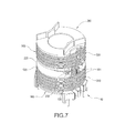
- This preferred embodiment comprises a plurality of wire crossing sections 301, a first winding section 310 and a second winding section 320, and the first winding section 310 and the second winding section 320 are arranged alternately with each other and each wire crossing section 301 is coupled between the adjacent first winding section 310 and second winding section 320, so that the conductive wire 300 can be wound around the first winding section 310 and the second winding section 320 in a multi-layer manner.
- the core module 400 includes an inner core 401 and two outer cores 410/420.
- the inner core 401 is an iron member clamped between the first bobbin 100 and the second bobbin 200 and preferably clamped between the first flapper 120 and the second flapper 220.
- the inner core 401 preferably includes a protruding core rod 402, and the core rod 402 is passed into the first shaft 110 (In other preferred embodiments, the core rod 402 is passed into the second shaft 210).
- Each outer core 410/420 is an iron member, and two outer cores 410/420 are installed at the other end of the first shaft 110 and the other end of the second shaft 210 respectively.
- Each outer core 410/420 includes a protruding core rod 411/421, and the two core rods 411/421 are passed into the first shaft 110 and the second shaft 210 respectively.
- the first pivoting portion 130 is pivotally coupled to the second pivoting portion 230, so that the first bobbin 100 and the second bobbin 200 can be pivoted with respect to each other, and a single conductive wire 300 can be wound around the first shaft 110 and the second shaft 210, and then the first bobbin 100 and the second bobbin 200 can be rotated and separated to facilitate manufacturers to install the inner core 401 between the first bobbin 100 and the second bobbin 200.
- the second pivoting portion 230 is detachably and pivotally coupled to the first pivoting portion 130, and/or the second snapping portion 240 is detachably latched to the first snapping portion 140, so that the first bobbin 100 and the second bobbin 200 can be pivoted and rotated by the first pivoting portion 130 and the second pivoting portion 230 to separate the second snapping portion 240 from the first snapping portion 140, and/or the first bobbin 100 and the second bobbin 200 can be pivoted and rotated by the first snapping portion 140 and the second snapping portion 240 to separate the second pivoting portion 230 from the first pivoting portion 130.
- the present disclosure can complete the process of winding two connected bobbins by a single conductive wire 300, and the modular bobbin 10 of the present disclosure may be applied in a single-wire winding process of two or more connected bobbins.
- the modular bobbin 10 is applied in the magnetic module of the first preferred embodiment and its structure is substantially the same as that of the first preferred embodiment.
- the difference between the modular bobbin 10 of this preferred embodiment and the modular bobbin 10 of the first preferred embodiment resides on that the first snapping portion 140 is a hook, and the second snapping portion 240 is a cam snapped to the first snapping portion 140.
- the first pivoting portion 130 is a shaft hole, and the second pivoting portion 230 is a cam pivotally coupled to the first pivoting portion 130.
- the modular bobbin 10 is applied in the magnetic module of the first preferred embodiment and its structure is substantially the same as that of the first preferred embodiment.
- the difference between the modular bobbin 10 of this preferred embodiment and the modular bobbin 10 of the first preferred embodiment resides on that the first pivoting portion 130 is a cam, and the second pivoting portion 230 is a hook pivotally coupled to the first pivoting portion 130, and the first snapping portion 140 is a hook, and the second snapping portion 240 is a cam snapped to the first snapping portion 140.
- the modular bobbin 10 is applied in the magnetic module of the first preferred embodiment and its structure is substantially the same as that of the first preferred embodiment.
- the difference between the modular bobbin 10 of this preferred embodiment and the modular bobbin 10 of the first preferred embodiment resides on that the first snapping portion 140 is a hook, and the second snapping portion 240 is a cam snapped to the first snapping portion 140.
- the modular bobbin 10 is applied in the magnetic module of the first preferred embodiment and its structure is substantially the same as that of the first preferred embodiment.
- the difference between the modular bobbin 10 of this preferred embodiment and the modular bobbin 10 of the first preferred embodiment resides on that the first snapping portion 140 and the second snapping portion 240 are a pair of hooks latched to one another.
Landscapes
- Engineering & Computer Science (AREA)
- Power Engineering (AREA)
- Electromagnets (AREA)
- Coils Or Transformers For Communication (AREA)
- Insulating Of Coils (AREA)
Abstract
Description
- The present disclosure relates to a bobbin of a magnetic module, and more particularly to a modular bobbin that can be detachably and pivotally connected.
- In general, the structure of a multiple winding transformer includes a plurality of bobbins connected with each other, and the bobbins are connected by male and female buckles, and thus the assembling process takes more time, and the male and female buckles may be broken easily when removing the buckles. In addition, the bobbins of the conventional multiple winding transformer are fixed after they are assembled, so that a wire cannot be wound from one bobbin to the other, or a core cannot be installed between the bobbins. As a result, most conventional multiple winding transformers require a plurality of conductive wires wound around the bobbins respectively, and then the core is installed between the bobbins, and the conductive wires are soldered and electrically conducted with one another.
- In view of the aforementioned drawbacks of the conventional multiple winding transformer, the inventor of the present disclosure based on years of experience in the related industry, and finally developed a magnetic module and a bobbin of the magnetic module in accordance with the present disclosure to overcome the drawbacks of the prior art.
- Therefore, it is a primary objective of the present disclosure to provide a magnetic module and a modular bobbin applied in the process of winding a plurality of bobbins by a single wire.
- To achieve the aforementioned objective, the present disclosure provides a magnetic module comprising a modular bobbin, a core module and a conductive wire. The modular bobbin comprises a first bobbin and a second bobbin, and the first bobbin includes a first shaft, and a first pivoting portion and a first snapping portion disposed at an end of the first shaft and arranged on two opposite sides of the end of the first shaft respectively, and the second bobbin includes a second shaft coaxially installed with the first shaft, and a second pivoting portion and a second snapping portion disposed at an end of the second shaft and arranged at two opposite sides of the end of the second shaft respectively, and the second pivoting portion is pivotally coupled to the first pivoting portion, and/or the second snapping portion is detachably latched to the first snapping portion, so that the first bobbin and the second bobbin may be pivoted and rotated by the first pivoting portion and the second pivoting portion to separate the second snapping portion from the first snapping portion, and/or the first bobbin and the second bobbin may be pivoted and rotated by the first snapping portion and the second snapping portion to separate the second pivoting portion from the first pivoting portion. The core module includes an inner core, and the inner core is situated between the first bobbin and the second bobbin when the second snapping portion is separated from the first snapping portion. The conductive wire is wound around the first shaft and the second shaft.
- Preferably, the first shaft has a first flapper, and the first pivoting portion is disposed at the first flapper, and the second shaft has a second flapper, and the second pivoting portion is disposed at the second flapper, and the inner core is installed between the first flapper and the second flapper. Preferably, a first wire crossing slot is formed at an end of the first flapper, and a second wire crossing slot is formed at an edge of the second flapper.
- Preferably, the conductive wire includes a wire crossing section, and a first winding section and a second winding section are extended from both ends of the wire crossing section and wound around the first shaft and the second shaft respectively, and the wire crossing section is disposed between the first flapper and the second flapper, and both ends of the wire crossing section are contained into the first wire crossing slot and the second wire crossing slot respectively. Preferably, the first wire crossing slot and the first pivoting portion are disposed adjacent to each other, and the first wire crossing slot is formed at a position corresponsive to the position of the second wire crossing slot, and the second wire crossing slot and the second pivoting portion are arranged adjacent to each other.
- Preferably, the first bobbin is connected to a second bobbin in different ways. For example, the first pivoting portion is a hook and the second pivoting portion is a cam pivotally coupled to the hook, or the first pivoting portion is a cam and the second pivoting portion is a hook pivotally latched to the cam. In other examples, the first pivoting portion and the second pivoting portion are a pair of hooks latched with each other, or the first snapping portion and the second snapping portion are a pair of hooks latched with each other. In other examples, the first snapping portion is a hook and the second snapping portion is a cam latched to the hook, or the first snapping portion is a cam and the second snapping portion is a hook latched to the cam.
- In the present disclosure, the first pivoting portion is pivotally coupled to the second pivoting portion, so that the first bobbin and the second bobbin can be pivoted with respect to each other, and a single conductive wire may be wound around the first shaft and the second shaft and then the first bobbin and the second bobbin are pivotally rotated and separated from each other to facilitate manufacturers to install the inner core between the first bobbin and the second bobbin. Compared with the prior art, the present disclosure is able to complete the process of winding two connected bobbins by a single conductive wire, and the modular bobbin of the present disclosure can be applied in the process of winding two or more bobbins.
-
-
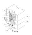
FIG. 1 is a perspective view of a magnetic module of a first preferred embodiment of the present disclosure; -
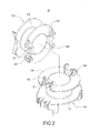
FIG. 2 is an exploded view of a magnetic module of the first preferred embodiment of the present disclosure; -
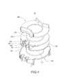
FIG. 3 is a perspective view of a modular bobbin of the first preferred embodiment of the present disclosure; -
FIG. 4 is another perspective view of a modular bobbin of the first preferred embodiment of the present disclosure; -
FIG. 5 is a sectional view of a modular bobbin of the first preferred embodiment of the present disclosure; -
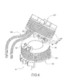
FIG. 6 is a schematic view of winding a modular bobbin of the first preferred embodiment of the present disclosure; -
FIG. 7 is another schematic view of winding a modular bobbin of the first preferred embodiment of the present disclosure; -
FIG. 8 is another schematic view of winding a modular bobbin of the first preferred embodiment of the present disclosure; -
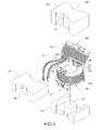
FIG. 9 is an exploded view of a magnetic module of the first preferred embodiment of the present disclosure; -
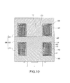
FIG. 10 is a sectional view of a magnetic module of the first preferred embodiment of the present disclosure; -
FIG. 11 is a schematic view of a modular bobbin of a second preferred embodiment of the present disclosure; -
FIG. 12 is a schematic view of a modular bobbin of a third preferred embodiment of the present disclosure; -
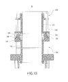
FIG. 13 is a schematic view of a modular bobbin of a fourth preferred embodiment of the present disclosure; and -
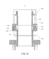
FIG. 14 is a schematic view of winding a modular bobbin of a fifth preferred embodiment of the present disclosure. - The technical contents of the present disclosure will become apparent with the detailed description of preferred embodiments accompanied with the illustration of related drawings as follows. It is noteworthy that same numerals are used for representing same respective elements in the drawings.
- With reference to
FIG. 1 for a magnetic module of the first preferred embodiment of the present disclosure, the magnetic module comprises amodular bobbin 10, aconductive wire 300, and acore module 400. - In
FIGS. 2 to 5 , themodular bobbin 10 includes afirst bobbin 100 and asecond bobbin 200. In this preferred embodiment, thefirst bobbin 100 includes afirst shaft 110 and afirst flapper 120. Thefirst shaft 110 is a hollow plastic column, and thefirst flapper 120 is radially extended from an end 111 of thefirst shaft 110. Thefirst flapper 120 has afirst pivoting portion 130 and afirst snapping portion 140 disposed on two opposite sides of the end 111 of thefirst shaft 110 respectively. In this preferred embodiment, thefirst pivoting portion 130 is a hook, and thefirst snapping portion 140 is a cam, but the present disclosure is not limited to such arrangements only. A firstwire crossing slot 121 is formed at an edge of thefirst flapper 120 and disposed adjacent to thefirst pivoting portion 130. - In this preferred embodiment, the
second bobbin 200 includes asecond shaft 210 and asecond flapper 220. Thesecond shaft 210 is a plastic hollow column, and thesecond shaft 210 and thefirst shaft 110 are coaxially installed, and thesecond flapper 220 is radially extended from an end 211 of thesecond shaft 210. Asecond pivoting portion 230 and asecond snapping portion 240 are disposed at thesecond flapper 220 and arranged on two opposite sides of the end 211 of thesecond shaft 210 respectively. In this preferred embodiment, thesecond pivoting portion 230 is a cam pivotally coupled to thefirst pivoting portion 130, and thesecond snapping portion 240 is a hook latched to thefirst snapping portion 140, but the present disclosure is not limited to such arrangements only. An edge of thesecond flapper 220 has a secondwire crossing slot 221 disposed adjacent to thesecond pivoting portion 230, and the firstwire crossing slot 121 is formed at a position corresponsive to the position of the secondwire crossing slot 221. - In
FIGS. 6 to 8 , theconductive wire 300 includes at least onewire crossing section 301, afirst winding section 310 and asecond winding section 320 extended from both ends of thewire crossing section 301 respectively and wound around thefirst shaft 110 and thesecond shaft 210 respectively, and thewire crossing section 301 is disposed between thefirst flapper 120 and thesecond flapper 220, and both ends of thewire crossing section 301 are contained in the firstwire crossing slot 121 and the secondwire crossing slot 221 respectively, and thewire crossing section 301 is disposed adjacent to thefirst pivoting portion 130 and thesecond pivoting portion 230. This preferred embodiment comprises a plurality ofwire crossing sections 301, afirst winding section 310 and asecond winding section 320, and thefirst winding section 310 and thesecond winding section 320 are arranged alternately with each other and eachwire crossing section 301 is coupled between the adjacentfirst winding section 310 andsecond winding section 320, so that theconductive wire 300 can be wound around thefirst winding section 310 and thesecond winding section 320 in a multi-layer manner. - In
FIGS. 9 and10 , thecore module 400 includes aninner core 401 and twoouter cores 410/420. Theinner core 401 is an iron member clamped between thefirst bobbin 100 and thesecond bobbin 200 and preferably clamped between thefirst flapper 120 and thesecond flapper 220. In this preferred embodiment, theinner core 401 preferably includes aprotruding core rod 402, and thecore rod 402 is passed into the first shaft 110 (In other preferred embodiments, thecore rod 402 is passed into the second shaft 210). - Each
outer core 410/420 is an iron member, and twoouter cores 410/420 are installed at the other end of thefirst shaft 110 and the other end of thesecond shaft 210 respectively. Eachouter core 410/420 includes aprotruding core rod 411/421, and the twocore rods 411/421 are passed into thefirst shaft 110 and thesecond shaft 210 respectively. - In the present disclosure, the
first pivoting portion 130 is pivotally coupled to thesecond pivoting portion 230, so that thefirst bobbin 100 and thesecond bobbin 200 can be pivoted with respect to each other, and a singleconductive wire 300 can be wound around thefirst shaft 110 and thesecond shaft 210, and then thefirst bobbin 100 and thesecond bobbin 200 can be rotated and separated to facilitate manufacturers to install theinner core 401 between thefirst bobbin 100 and thesecond bobbin 200. More specifically, thesecond pivoting portion 230 is detachably and pivotally coupled to thefirst pivoting portion 130, and/or thesecond snapping portion 240 is detachably latched to thefirst snapping portion 140, so that thefirst bobbin 100 and thesecond bobbin 200 can be pivoted and rotated by thefirst pivoting portion 130 and thesecond pivoting portion 230 to separate thesecond snapping portion 240 from thefirst snapping portion 140, and/or thefirst bobbin 100 and thesecond bobbin 200 can be pivoted and rotated by thefirst snapping portion 140 and thesecond snapping portion 240 to separate thesecond pivoting portion 230 from thefirst pivoting portion 130. Compared with the prior art, the present disclosure can complete the process of winding two connected bobbins by a singleconductive wire 300, and themodular bobbin 10 of the present disclosure may be applied in a single-wire winding process of two or more connected bobbins. - With reference to
FIG. 11 for a modular bobbin of the second preferred embodiment of the present disclosure, themodular bobbin 10 is applied in the magnetic module of the first preferred embodiment and its structure is substantially the same as that of the first preferred embodiment. The difference between themodular bobbin 10 of this preferred embodiment and themodular bobbin 10 of the first preferred embodiment resides on that thefirst snapping portion 140 is a hook, and thesecond snapping portion 240 is a cam snapped to thefirst snapping portion 140. In addition, thefirst pivoting portion 130 is a shaft hole, and thesecond pivoting portion 230 is a cam pivotally coupled to thefirst pivoting portion 130. - With reference to
FIG. 12 for a modular bobbin of the third preferred embodiment of the present disclosure, themodular bobbin 10 is applied in the magnetic module of the first preferred embodiment and its structure is substantially the same as that of the first preferred embodiment. The difference between themodular bobbin 10 of this preferred embodiment and themodular bobbin 10 of the first preferred embodiment resides on that thefirst pivoting portion 130 is a cam, and thesecond pivoting portion 230 is a hook pivotally coupled to thefirst pivoting portion 130, and thefirst snapping portion 140 is a hook, and thesecond snapping portion 240 is a cam snapped to thefirst snapping portion 140. - With reference to
FIG. 13 for a modular bobbin of the fourth preferred embodiment of the present disclosure, themodular bobbin 10 is applied in the magnetic module of the first preferred embodiment and its structure is substantially the same as that of the first preferred embodiment. The difference between themodular bobbin 10 of this preferred embodiment and themodular bobbin 10 of the first preferred embodiment resides on that thefirst snapping portion 140 is a hook, and thesecond snapping portion 240 is a cam snapped to thefirst snapping portion 140. - With reference to
FIG. 14 for a modular bobbin of the fifth preferred embodiment of the present disclosure, themodular bobbin 10 is applied in the magnetic module of the first preferred embodiment and its structure is substantially the same as that of the first preferred embodiment. The difference between themodular bobbin 10 of this preferred embodiment and themodular bobbin 10 of the first preferred embodiment resides on that thefirst snapping portion 140 and thesecond snapping portion 240 are a pair of hooks latched to one another.
Claims (15)
- A modular bobbin 10, comprising:a first bobbin 100, including a first shaft 110, and a first pivoting portion 130 and a first snapping portion 140 disposed at an end 111 of the first shaft 110, and the first pivoting portion 130 and the first snapping portion 140 being arranged on opposite sides of the end 111 of the first shaft 110 respectively; anda second bobbin 200, including a second shaft 210 coaxially installed with the first shaft 110, and a second pivoting portion 230 and a second snapping portion 240 disposed at an end 211 of the second shaft 210 and arranged at two opposite sides of the end 211 of the second shaft 210 respectively, and the second pivoting portion 230 being pivotally coupled to the first pivoting portion 130, and the second snapping portion 240 being detachably latched to the first snapping portion 140, so that the first bobbin 100 and the second bobbin 200 may be pivoted and rotated by the first pivoting portion 130 and the second pivoting portion 230 to separate the second snapping portion 240 from the first snapping portion 140.
- The modular bobbin 10 of claim 1, wherein the second pivoting portion 230 is detachably and pivotally coupled to the first pivoting portion 130, such that the first bobbin 100 and the second bobbin 200 may be rotated by using the first snapping portion 140 and the second snapping portion 240 as a pivot to separate the second pivoting portion 230 from the first pivoting portion 130.
- The modular bobbin 10 of claim 1, wherein the end 111 of the first shaft 110 has a first flapper 120 and the first pivoting portion 130 is disposed at the first flapper 120, and the end 211 of the second shaft 210 has a second flapper 220, and the second pivoting portion 230 is disposed at the second flapper 220, and the first flapper 120 has a first wire crossing slot 121 formed at an edge of the first flapper 120, and the second flapper 220 has a second wire crossing slot 221 formed at an edge of the second flapper 220.
- The modular bobbin 10 of claim 3, wherein the first wire crossing slot 121 is formed at a position corresponsive to the position of the second wire crossing slot 221, and the first wire crossing slot 121 and the first pivoting portion 130 are disposed adjacent to each other, and the second wire crossing slot 221 and the second pivoting portion 230 are disposed adjacent to each other.
- The modular bobbin 10 of claim 1 or 2, wherein the first pivoting portion 130 is a hook, and the second pivoting portion 230 is a cam pivotally coupled to the hook.
- The modular bobbin 10 of claim 1 or 2, wherein the first pivoting portion 130 is a cam, and the second pivoting portion 230 is a hook pivotally coupled to the cam.
- The modular bobbin 10 of claim 1 or 2, wherein the first pivoting portion 130 and the second pivoting portion 230 are a pair of hooks latched to each other.
- The modular bobbin 10 of claim 1 or 2, wherein the first snapping portion 140 and the second snapping portion 240 are a pair of hooks latched to each other.
- The modular bobbin 10 of claim 1 or 2, wherein the first snapping portion 140 is a hook, and the second snapping portion 240 is a cam latched to the hook.
- The modular bobbin 10 of claim 1 or 2, wherein the first snapping portion 140 is a cam, and the second snapping portion 240 is a hook latched to the cam.
- A magnetic module, comprising:a modular bobbin 10, including a first bobbin 100 and a second bobbin 200, and the first bobbin 100 including a first shaft 110, and an end 111 of the first shaft 110 having a first pivoting portion 130 and a first snapping portion 140, and the first pivoting portion 130 andthe first snapping portion 140 being disposed on two opposite sides of the end 111 of the first shaft 110, and the second bobbin 200 including a second shaft 210 coaxially installed with the first shaft 110, and an end 211 of the second shaft 210 having a second pivoting portion 230 and a second snapping portion 240 disposed on two opposite sides of the end 211 of the second shaft 210 respectively, and the second pivoting portion 230 being pivotally coupled to the first pivoting portion 130, and the second snapping portion 240 being separately latched to the first snapping portion 140, so that the first bobbin 100 and the second bobbin 200 may be pivoted and rotated by the first pivoting portion 130 and the second pivoting portion 230 to separate the second snapping portion 240 from the first snapping portion 140;a core module 400, including an inner core 401, and the inner core 401 being situated between the first bobbin 100 and the second bobbin 200 when the second snapping portion 240 is separated from the first snapping portion 140; anda conductive wire 300, wound around the first shaft 110 and the second shaft 210.
- The modular bobbin 10 of claim 11, wherein the second pivoting portion 230 is detachably and pivotally coupled to the first pivoting portion 130, so that the first bobbin 100 and the second bobbin 200 may be pivoted and rotated by the first snapping portion 140 and the second snapping portion 240 to separate the second pivoting portion 230 from the first pivoting portion 130.
- The modular bobbin 10 of claim 11 or 12, wherein the end 111 of the first shaft 110 has a first flapper 120 and the first pivoting portion 130 is disposed at the first flapper 120, and the end 211 of the second shaft 210 has a second flapper 220, and the second pivoting portion 230 is disposed at the second flapper 220, and the inner core 401 is installed between the first flapper 120 and the second flapper 220, and the modular bobbin 10 of claim 15, wherein the first flapper 120 has a first wire crossing slot 121 formed at an edge of the first flapper 120, and the second flapper 220 has a first wire crossing slot 221 formed at an edge of the first wire crossing slot 221.
- The modular bobbin 10 of claim 11, wherein the conductive wire 300 includes a wire crossing section 301, and a first winding section 310 and a second winding section 320 are extended from both ends of the wire crossing section 301 respectively, the first winding section 310 and the second winding section 320 are wound around the first shaft 110 and the second shaft 210 respectively, and the wire crossing section 301 is disposed between the first flapper 120 and the second flapper 220, and both ends of the wire crossing section 301 are contained in the first wire crossing slot 121 and the second wire crossing slot 221 respectively.
- The modular bobbin 10 of claim 11, wherein the first wire crossing slot 121 is formed at a position corresponsive to the position of the second wire crossing slot 221, and the first wire crossing slot 121 and the first pivoting portion 130 are disposed adjacent to each other, and the second wire crossing slot 221 and the second pivoting portion 230 are disposed adjacent to each other.
Applications Claiming Priority (1)
| Application Number | Priority Date | Filing Date | Title |
|---|---|---|---|
| TW103126107A TWI505302B (en) | 2014-07-30 | 2014-07-30 | Magnetic Module and Modular Bobbin thereof |
Publications (2)
| Publication Number | Publication Date |
|---|---|
| EP2980812A1 true EP2980812A1 (en) | 2016-02-03 |
| EP2980812B1 EP2980812B1 (en) | 2017-06-28 |
Family
ID=51900301
Family Applications (1)
| Application Number | Title | Priority Date | Filing Date |
|---|---|---|---|
| EP14193421.6A Active EP2980812B1 (en) | 2014-07-30 | 2014-11-17 | Magnetic module and modular bobbin thereof |
Country Status (3)
| Country | Link |
|---|---|
| US (1) | US20160031673A1 (en) |
| EP (1) | EP2980812B1 (en) |
| TW (1) | TWI505302B (en) |
Cited By (1)
| Publication number | Priority date | Publication date | Assignee | Title |
|---|---|---|---|---|
| WO2016193958A1 (en) * | 2015-06-04 | 2016-12-08 | Manfred Schmelzer Gmbh | Low-noise special transformer |
Families Citing this family (6)
| Publication number | Priority date | Publication date | Assignee | Title |
|---|---|---|---|---|
| US11721476B1 (en) * | 2015-11-05 | 2023-08-08 | St Jude Medical International Holding S.À R.L. | Sensor coil assembly |
| DE102016221866B4 (en) | 2016-11-08 | 2024-05-16 | Würth Elektronik eiSos Gmbh & Co. KG | Inductive component and method for automated production of the inductive component |
| TWI640020B (en) * | 2017-07-28 | 2018-11-01 | 群光電能科技股份有限公司 | Adapter, transformer, winding frame and transformer assembly method |
| US11562854B1 (en) * | 2019-07-12 | 2023-01-24 | Bel Power Solutions Inc. | Dual slotted bobbin magnetic component with two-legged core |
| CN111559673B (en) * | 2020-05-12 | 2021-02-19 | 上海布鲁可积木科技有限公司 | Receive traditional thread binding putting and concatenation building blocks suitable for concatenation building blocks |
| JP7708627B2 (en) * | 2021-09-16 | 2025-07-15 | Tdk株式会社 | Coil device |
Citations (3)
| Publication number | Priority date | Publication date | Assignee | Title |
|---|---|---|---|---|
| US3843946A (en) * | 1973-10-05 | 1974-10-22 | Original Equipment Motors Inc | Dual bobbin assembly for coils |
| US4103268A (en) * | 1977-06-29 | 1978-07-25 | Gte Automatic Electric Laboratories Incorporated | Dual coil hinged bobbin assembly |
| US20110025304A1 (en) * | 2009-07-31 | 2011-02-03 | James Douglas Lint | Current sensing devices and methods |
Family Cites Families (15)
| Publication number | Priority date | Publication date | Assignee | Title |
|---|---|---|---|---|
| US3510858A (en) * | 1967-09-08 | 1970-05-05 | Foxboro Co | Force-balance instrument with electrical detector arrangement |
| JPS55145306A (en) * | 1979-04-28 | 1980-11-12 | Matsushita Electric Works Ltd | Connecting structure of coil bobbin |
| US4462016A (en) * | 1982-12-03 | 1984-07-24 | At&T Technologies, Inc. | Inductor coils with mechanically coupleable bobbins |
| JPS60113913A (en) * | 1983-11-25 | 1985-06-20 | Matsushita Electric Ind Co Ltd | Coil bobbin |
| JP2566052Y2 (en) * | 1992-01-27 | 1998-03-25 | 株式会社トーキン | Trance |
| JP3104548B2 (en) * | 1994-10-05 | 2000-10-30 | 東芝ライテック株式会社 | Electromagnetic equipment |
| TW200845058A (en) * | 2007-05-11 | 2008-11-16 | Delta Electronics Inc | Combined transformer |
| US7859380B2 (en) * | 2008-02-07 | 2010-12-28 | Tyco Electronics Corporation | Bobbin assembly |
| TWI404082B (en) * | 2008-04-25 | 2013-08-01 | Delta Electronics Inc | Splitter |
| JP2010212380A (en) * | 2009-03-09 | 2010-09-24 | Tdk Corp | Winding wire frame and winding wire component |
| US9823274B2 (en) * | 2009-07-31 | 2017-11-21 | Pulse Electronics, Inc. | Current sensing inductive devices |
| US9151782B2 (en) * | 2009-07-31 | 2015-10-06 | Pulse Electronics, Inc. | Current sensing devices and methods |
| TWI379326B (en) * | 2009-11-19 | 2012-12-11 | Delta Electronics Inc | Transformer with modular winding bobbin devices |
| TWI449068B (en) * | 2012-03-21 | 2014-08-11 | Delta Electronics Inc | Magnetic component and bobbin thereof |
| US9236179B1 (en) * | 2013-11-26 | 2016-01-12 | Universal Lighting Technologies, Inc. | Magnetic component apparatus with interconnectable bobbins |
-
2014
- 2014-07-30 TW TW103126107A patent/TWI505302B/en active
- 2014-11-17 US US14/543,151 patent/US20160031673A1/en not_active Abandoned
- 2014-11-17 EP EP14193421.6A patent/EP2980812B1/en active Active
Patent Citations (3)
| Publication number | Priority date | Publication date | Assignee | Title |
|---|---|---|---|---|
| US3843946A (en) * | 1973-10-05 | 1974-10-22 | Original Equipment Motors Inc | Dual bobbin assembly for coils |
| US4103268A (en) * | 1977-06-29 | 1978-07-25 | Gte Automatic Electric Laboratories Incorporated | Dual coil hinged bobbin assembly |
| US20110025304A1 (en) * | 2009-07-31 | 2011-02-03 | James Douglas Lint | Current sensing devices and methods |
Cited By (1)
| Publication number | Priority date | Publication date | Assignee | Title |
|---|---|---|---|---|
| WO2016193958A1 (en) * | 2015-06-04 | 2016-12-08 | Manfred Schmelzer Gmbh | Low-noise special transformer |
Also Published As
| Publication number | Publication date |
|---|---|
| EP2980812B1 (en) | 2017-06-28 |
| TWI505302B (en) | 2015-10-21 |
| US20160031673A1 (en) | 2016-02-04 |
| TW201604906A (en) | 2016-02-01 |
Similar Documents
| Publication | Publication Date | Title |
|---|---|---|
| EP2980812B1 (en) | Magnetic module and modular bobbin thereof | |
| CN1949415B (en) | Coiling sheet stype common mode choking coil | |
| US8686822B2 (en) | Surface mounted pulse transformer | |
| JP2011243663A (en) | Coil component, reactor, and method for forming the coil component | |
| CN205248028U (en) | Pulse transformer | |
| JP3189669U (en) | Improved bobbin structure | |
| JP2013501369A5 (en) | Current compensation choke | |
| TW201331963A (en) | Improved structure of iron core of regulator | |
| US9004389B2 (en) | Bobbin and method of using the same | |
| TWM504334U (en) | Two-axis thin wire frame improved structure | |
| KR101632071B1 (en) | Bobbin type Transformer and manufacturing method thereof | |
| JP5408030B2 (en) | Coil parts, reactor, and method for forming coil parts | |
| CN103971904A (en) | Accessories for Transformer Skeleton | |
| CN204144030U (en) | Wire winding pins for network transformers and network transformers | |
| TWI601166B (en) | Bobbin, transformer and method of winding wires on bobbin | |
| CN203085323U (en) | Transformer | |
| JP2013074144A5 (en) | ||
| JP5174106B2 (en) | Coil parts | |
| JP2008258239A (en) | Bobbin for winding wire | |
| CN210516433U (en) | a transformer | |
| CN103106954A (en) | Cable assembly | |
| CN203941809U (en) | Transformer winding structure | |
| US8854172B2 (en) | Inductor and transformer | |
| JP2006303304A5 (en) | ||
| CN203787250U (en) | Inductors that can increase the current |
Legal Events
| Date | Code | Title | Description |
|---|---|---|---|
| PUAI | Public reference made under article 153(3) epc to a published international application that has entered the european phase |
Free format text: ORIGINAL CODE: 0009012 |
|
| AK | Designated contracting states |
Kind code of ref document: A1 Designated state(s): AL AT BE BG CH CY CZ DE DK EE ES FI FR GB GR HR HU IE IS IT LI LT LU LV MC MK MT NL NO PL PT RO RS SE SI SK SM TR |
|
| AX | Request for extension of the european patent |
Extension state: BA ME |
|
| 17P | Request for examination filed |
Effective date: 20160603 |
|
| RBV | Designated contracting states (corrected) |
Designated state(s): AL AT BE BG CH CY CZ DE DK EE ES FI FR GB GR HR HU IE IS IT LI LT LU LV MC MK MT NL NO PL PT RO RS SE SI SK SM TR |
|
| GRAP | Despatch of communication of intention to grant a patent |
Free format text: ORIGINAL CODE: EPIDOSNIGR1 |
|
| STAA | Information on the status of an ep patent application or granted ep patent |
Free format text: STATUS: GRANT OF PATENT IS INTENDED |
|
| INTG | Intention to grant announced |
Effective date: 20161107 |
|
| RAP1 | Party data changed (applicant data changed or rights of an application transferred) |
Owner name: DELTA ELECTRONICS, INC. |
|
| GRAS | Grant fee paid |
Free format text: ORIGINAL CODE: EPIDOSNIGR3 |
|
| GRAJ | Information related to disapproval of communication of intention to grant by the applicant or resumption of examination proceedings by the epo deleted |
Free format text: ORIGINAL CODE: EPIDOSDIGR1 |
|
| GRAL | Information related to payment of fee for publishing/printing deleted |
Free format text: ORIGINAL CODE: EPIDOSDIGR3 |
|
| STAA | Information on the status of an ep patent application or granted ep patent |
Free format text: STATUS: REQUEST FOR EXAMINATION WAS MADE |
|
| GRAP | Despatch of communication of intention to grant a patent |
Free format text: ORIGINAL CODE: EPIDOSNIGR1 |
|
| STAA | Information on the status of an ep patent application or granted ep patent |
Free format text: STATUS: GRANT OF PATENT IS INTENDED |
|
| INTC | Intention to grant announced (deleted) | ||
| INTG | Intention to grant announced |
Effective date: 20170426 |
|
| GRAA | (expected) grant |
Free format text: ORIGINAL CODE: 0009210 |
|
| STAA | Information on the status of an ep patent application or granted ep patent |
Free format text: STATUS: THE PATENT HAS BEEN GRANTED |
|
| AK | Designated contracting states |
Kind code of ref document: B1 Designated state(s): AL AT BE BG CH CY CZ DE DK EE ES FI FR GB GR HR HU IE IS IT LI LT LU LV MC MK MT NL NO PL PT RO RS SE SI SK SM TR |
|
| REG | Reference to a national code |
Ref country code: GB Ref legal event code: FG4D |
|
| REG | Reference to a national code |
Ref country code: CH Ref legal event code: EP |
|
| REG | Reference to a national code |
Ref country code: CH Ref legal event code: NV Representative=s name: WEINMANN ZIMMERLI, CH |
|
| REG | Reference to a national code |
Ref country code: AT Ref legal event code: REF Ref document number: 905515 Country of ref document: AT Kind code of ref document: T Effective date: 20170715 |
|
| REG | Reference to a national code |
Ref country code: IE Ref legal event code: FG4D |
|
| REG | Reference to a national code |
Ref country code: DE Ref legal event code: R096 Ref document number: 602014011185 Country of ref document: DE |
|
| REG | Reference to a national code |
Ref country code: NO Ref legal event code: T2 Effective date: 20170628 |
|
| PG25 | Lapsed in a contracting state [announced via postgrant information from national office to epo] |
Ref country code: HR Free format text: LAPSE BECAUSE OF FAILURE TO SUBMIT A TRANSLATION OF THE DESCRIPTION OR TO PAY THE FEE WITHIN THE PRESCRIBED TIME-LIMIT Effective date: 20170628 Ref country code: LT Free format text: LAPSE BECAUSE OF FAILURE TO SUBMIT A TRANSLATION OF THE DESCRIPTION OR TO PAY THE FEE WITHIN THE PRESCRIBED TIME-LIMIT Effective date: 20170628 Ref country code: GR Free format text: LAPSE BECAUSE OF FAILURE TO SUBMIT A TRANSLATION OF THE DESCRIPTION OR TO PAY THE FEE WITHIN THE PRESCRIBED TIME-LIMIT Effective date: 20170929 Ref country code: FI Free format text: LAPSE BECAUSE OF FAILURE TO SUBMIT A TRANSLATION OF THE DESCRIPTION OR TO PAY THE FEE WITHIN THE PRESCRIBED TIME-LIMIT Effective date: 20170628 |
|
| REG | Reference to a national code |
Ref country code: NL Ref legal event code: MP Effective date: 20170628 |
|
| REG | Reference to a national code |
Ref country code: LT Ref legal event code: MG4D |
|
| REG | Reference to a national code |
Ref country code: AT Ref legal event code: MK05 Ref document number: 905515 Country of ref document: AT Kind code of ref document: T Effective date: 20170628 |
|
| PG25 | Lapsed in a contracting state [announced via postgrant information from national office to epo] |
Ref country code: LV Free format text: LAPSE BECAUSE OF FAILURE TO SUBMIT A TRANSLATION OF THE DESCRIPTION OR TO PAY THE FEE WITHIN THE PRESCRIBED TIME-LIMIT Effective date: 20170628 Ref country code: NL Free format text: LAPSE BECAUSE OF FAILURE TO SUBMIT A TRANSLATION OF THE DESCRIPTION OR TO PAY THE FEE WITHIN THE PRESCRIBED TIME-LIMIT Effective date: 20170628 Ref country code: RS Free format text: LAPSE BECAUSE OF FAILURE TO SUBMIT A TRANSLATION OF THE DESCRIPTION OR TO PAY THE FEE WITHIN THE PRESCRIBED TIME-LIMIT Effective date: 20170628 Ref country code: SE Free format text: LAPSE BECAUSE OF FAILURE TO SUBMIT A TRANSLATION OF THE DESCRIPTION OR TO PAY THE FEE WITHIN THE PRESCRIBED TIME-LIMIT Effective date: 20170628 Ref country code: BG Free format text: LAPSE BECAUSE OF FAILURE TO SUBMIT A TRANSLATION OF THE DESCRIPTION OR TO PAY THE FEE WITHIN THE PRESCRIBED TIME-LIMIT Effective date: 20170928 |
|
| PG25 | Lapsed in a contracting state [announced via postgrant information from national office to epo] |
Ref country code: SK Free format text: LAPSE BECAUSE OF FAILURE TO SUBMIT A TRANSLATION OF THE DESCRIPTION OR TO PAY THE FEE WITHIN THE PRESCRIBED TIME-LIMIT Effective date: 20170628 Ref country code: RO Free format text: LAPSE BECAUSE OF FAILURE TO SUBMIT A TRANSLATION OF THE DESCRIPTION OR TO PAY THE FEE WITHIN THE PRESCRIBED TIME-LIMIT Effective date: 20170628 Ref country code: CZ Free format text: LAPSE BECAUSE OF FAILURE TO SUBMIT A TRANSLATION OF THE DESCRIPTION OR TO PAY THE FEE WITHIN THE PRESCRIBED TIME-LIMIT Effective date: 20170628 Ref country code: EE Free format text: LAPSE BECAUSE OF FAILURE TO SUBMIT A TRANSLATION OF THE DESCRIPTION OR TO PAY THE FEE WITHIN THE PRESCRIBED TIME-LIMIT Effective date: 20170628 Ref country code: AT Free format text: LAPSE BECAUSE OF FAILURE TO SUBMIT A TRANSLATION OF THE DESCRIPTION OR TO PAY THE FEE WITHIN THE PRESCRIBED TIME-LIMIT Effective date: 20170628 |
|
| PG25 | Lapsed in a contracting state [announced via postgrant information from national office to epo] |
Ref country code: PL Free format text: LAPSE BECAUSE OF FAILURE TO SUBMIT A TRANSLATION OF THE DESCRIPTION OR TO PAY THE FEE WITHIN THE PRESCRIBED TIME-LIMIT Effective date: 20170628 Ref country code: SM Free format text: LAPSE BECAUSE OF FAILURE TO SUBMIT A TRANSLATION OF THE DESCRIPTION OR TO PAY THE FEE WITHIN THE PRESCRIBED TIME-LIMIT Effective date: 20170628 Ref country code: IS Free format text: LAPSE BECAUSE OF FAILURE TO SUBMIT A TRANSLATION OF THE DESCRIPTION OR TO PAY THE FEE WITHIN THE PRESCRIBED TIME-LIMIT Effective date: 20171028 Ref country code: IT Free format text: LAPSE BECAUSE OF FAILURE TO SUBMIT A TRANSLATION OF THE DESCRIPTION OR TO PAY THE FEE WITHIN THE PRESCRIBED TIME-LIMIT Effective date: 20170628 Ref country code: ES Free format text: LAPSE BECAUSE OF FAILURE TO SUBMIT A TRANSLATION OF THE DESCRIPTION OR TO PAY THE FEE WITHIN THE PRESCRIBED TIME-LIMIT Effective date: 20170628 |
|
| REG | Reference to a national code |
Ref country code: DE Ref legal event code: R097 Ref document number: 602014011185 Country of ref document: DE |
|
| PG25 | Lapsed in a contracting state [announced via postgrant information from national office to epo] |
Ref country code: DK Free format text: LAPSE BECAUSE OF FAILURE TO SUBMIT A TRANSLATION OF THE DESCRIPTION OR TO PAY THE FEE WITHIN THE PRESCRIBED TIME-LIMIT Effective date: 20170628 |
|
| PLBE | No opposition filed within time limit |
Free format text: ORIGINAL CODE: 0009261 |
|
| STAA | Information on the status of an ep patent application or granted ep patent |
Free format text: STATUS: NO OPPOSITION FILED WITHIN TIME LIMIT |
|
| 26N | No opposition filed |
Effective date: 20180329 |
|
| PG25 | Lapsed in a contracting state [announced via postgrant information from national office to epo] |
Ref country code: MC Free format text: LAPSE BECAUSE OF FAILURE TO SUBMIT A TRANSLATION OF THE DESCRIPTION OR TO PAY THE FEE WITHIN THE PRESCRIBED TIME-LIMIT Effective date: 20170628 |
|
| PG25 | Lapsed in a contracting state [announced via postgrant information from national office to epo] |
Ref country code: LU Free format text: LAPSE BECAUSE OF NON-PAYMENT OF DUE FEES Effective date: 20171117 Ref country code: SI Free format text: LAPSE BECAUSE OF FAILURE TO SUBMIT A TRANSLATION OF THE DESCRIPTION OR TO PAY THE FEE WITHIN THE PRESCRIBED TIME-LIMIT Effective date: 20170628 |
|
| REG | Reference to a national code |
Ref country code: FR Ref legal event code: ST Effective date: 20180731 Ref country code: BE Ref legal event code: MM Effective date: 20171130 |
|
| REG | Reference to a national code |
Ref country code: IE Ref legal event code: MM4A |
|
| PG25 | Lapsed in a contracting state [announced via postgrant information from national office to epo] |
Ref country code: MT Free format text: LAPSE BECAUSE OF NON-PAYMENT OF DUE FEES Effective date: 20171117 |
|
| PG25 | Lapsed in a contracting state [announced via postgrant information from national office to epo] |
Ref country code: FR Free format text: LAPSE BECAUSE OF NON-PAYMENT OF DUE FEES Effective date: 20171130 Ref country code: IE Free format text: LAPSE BECAUSE OF NON-PAYMENT OF DUE FEES Effective date: 20171117 |
|
| PG25 | Lapsed in a contracting state [announced via postgrant information from national office to epo] |
Ref country code: BE Free format text: LAPSE BECAUSE OF NON-PAYMENT OF DUE FEES Effective date: 20171130 |
|
| PG25 | Lapsed in a contracting state [announced via postgrant information from national office to epo] |
Ref country code: HU Free format text: LAPSE BECAUSE OF FAILURE TO SUBMIT A TRANSLATION OF THE DESCRIPTION OR TO PAY THE FEE WITHIN THE PRESCRIBED TIME-LIMIT; INVALID AB INITIO Effective date: 20141117 |
|
| GBPC | Gb: european patent ceased through non-payment of renewal fee |
Effective date: 20181117 |
|
| PG25 | Lapsed in a contracting state [announced via postgrant information from national office to epo] |
Ref country code: CY Free format text: LAPSE BECAUSE OF FAILURE TO SUBMIT A TRANSLATION OF THE DESCRIPTION OR TO PAY THE FEE WITHIN THE PRESCRIBED TIME-LIMIT Effective date: 20170628 |
|
| PG25 | Lapsed in a contracting state [announced via postgrant information from national office to epo] |
Ref country code: MK Free format text: LAPSE BECAUSE OF FAILURE TO SUBMIT A TRANSLATION OF THE DESCRIPTION OR TO PAY THE FEE WITHIN THE PRESCRIBED TIME-LIMIT Effective date: 20170628 |
|
| PG25 | Lapsed in a contracting state [announced via postgrant information from national office to epo] |
Ref country code: GB Free format text: LAPSE BECAUSE OF NON-PAYMENT OF DUE FEES Effective date: 20181117 |
|
| PG25 | Lapsed in a contracting state [announced via postgrant information from national office to epo] |
Ref country code: TR Free format text: LAPSE BECAUSE OF FAILURE TO SUBMIT A TRANSLATION OF THE DESCRIPTION OR TO PAY THE FEE WITHIN THE PRESCRIBED TIME-LIMIT Effective date: 20170628 |
|
| PG25 | Lapsed in a contracting state [announced via postgrant information from national office to epo] |
Ref country code: PT Free format text: LAPSE BECAUSE OF FAILURE TO SUBMIT A TRANSLATION OF THE DESCRIPTION OR TO PAY THE FEE WITHIN THE PRESCRIBED TIME-LIMIT Effective date: 20170628 |
|
| PG25 | Lapsed in a contracting state [announced via postgrant information from national office to epo] |
Ref country code: AL Free format text: LAPSE BECAUSE OF FAILURE TO SUBMIT A TRANSLATION OF THE DESCRIPTION OR TO PAY THE FEE WITHIN THE PRESCRIBED TIME-LIMIT Effective date: 20170628 |
|
| PGFP | Annual fee paid to national office [announced via postgrant information from national office to epo] |
Ref country code: DE Payment date: 20240925 Year of fee payment: 11 |
|
| PGFP | Annual fee paid to national office [announced via postgrant information from national office to epo] |
Ref country code: NO Payment date: 20241111 Year of fee payment: 11 |
|
| PGFP | Annual fee paid to national office [announced via postgrant information from national office to epo] |
Ref country code: CH Payment date: 20241201 Year of fee payment: 11 |