EP2980524A1 - Shift position detection device - Google Patents
Shift position detection device Download PDFInfo
- Publication number
- EP2980524A1 EP2980524A1 EP14773150.9A EP14773150A EP2980524A1 EP 2980524 A1 EP2980524 A1 EP 2980524A1 EP 14773150 A EP14773150 A EP 14773150A EP 2980524 A1 EP2980524 A1 EP 2980524A1
- Authority
- EP
- European Patent Office
- Prior art keywords
- shift position
- detection
- detection signal
- shift
- detection device
- Prior art date
- Legal status (The legal status is an assumption and is not a legal conclusion. Google has not performed a legal analysis and makes no representation as to the accuracy of the status listed.)
- Withdrawn
Links
Images

Classifications
-
- G—PHYSICS
- G01—MEASURING; TESTING
- G01D—MEASURING NOT SPECIALLY ADAPTED FOR A SPECIFIC VARIABLE; ARRANGEMENTS FOR MEASURING TWO OR MORE VARIABLES NOT COVERED IN A SINGLE OTHER SUBCLASS; TARIFF METERING APPARATUS; MEASURING OR TESTING NOT OTHERWISE PROVIDED FOR
- G01D5/00—Mechanical means for transferring the output of a sensing member; Means for converting the output of a sensing member to another variable where the form or nature of the sensing member does not constrain the means for converting; Transducers not specially adapted for a specific variable
- G01D5/12—Mechanical means for transferring the output of a sensing member; Means for converting the output of a sensing member to another variable where the form or nature of the sensing member does not constrain the means for converting; Transducers not specially adapted for a specific variable using electric or magnetic means
-
- G—PHYSICS
- G01—MEASURING; TESTING
- G01D—MEASURING NOT SPECIALLY ADAPTED FOR A SPECIFIC VARIABLE; ARRANGEMENTS FOR MEASURING TWO OR MORE VARIABLES NOT COVERED IN A SINGLE OTHER SUBCLASS; TARIFF METERING APPARATUS; MEASURING OR TESTING NOT OTHERWISE PROVIDED FOR
- G01D5/00—Mechanical means for transferring the output of a sensing member; Means for converting the output of a sensing member to another variable where the form or nature of the sensing member does not constrain the means for converting; Transducers not specially adapted for a specific variable
- G01D5/12—Mechanical means for transferring the output of a sensing member; Means for converting the output of a sensing member to another variable where the form or nature of the sensing member does not constrain the means for converting; Transducers not specially adapted for a specific variable using electric or magnetic means
- G01D5/14—Mechanical means for transferring the output of a sensing member; Means for converting the output of a sensing member to another variable where the form or nature of the sensing member does not constrain the means for converting; Transducers not specially adapted for a specific variable using electric or magnetic means influencing the magnitude of a current or voltage
- G01D5/142—Mechanical means for transferring the output of a sensing member; Means for converting the output of a sensing member to another variable where the form or nature of the sensing member does not constrain the means for converting; Transducers not specially adapted for a specific variable using electric or magnetic means influencing the magnitude of a current or voltage using Hall-effect devices
- G01D5/145—Mechanical means for transferring the output of a sensing member; Means for converting the output of a sensing member to another variable where the form or nature of the sensing member does not constrain the means for converting; Transducers not specially adapted for a specific variable using electric or magnetic means influencing the magnitude of a current or voltage using Hall-effect devices influenced by the relative movement between the Hall device and magnetic fields
-
- G—PHYSICS
- G01—MEASURING; TESTING
- G01D—MEASURING NOT SPECIALLY ADAPTED FOR A SPECIFIC VARIABLE; ARRANGEMENTS FOR MEASURING TWO OR MORE VARIABLES NOT COVERED IN A SINGLE OTHER SUBCLASS; TARIFF METERING APPARATUS; MEASURING OR TESTING NOT OTHERWISE PROVIDED FOR
- G01D2205/00—Indexing scheme relating to details of means for transferring or converting the output of a sensing member
- G01D2205/70—Position sensors comprising a moving target with particular shapes, e.g. of soft magnetic targets
- G01D2205/77—Specific profiles
- G01D2205/777—Whorl-shaped profiles
Definitions
- the present invention relates to a shift position detection device.
- Patent Literature 1 As a conventional shift position detection device, for example, there is the one disclosed in Patent Literature 1.
- Patent Literature 1 Japanese Unexamined Patent Application Publication No. 2003-208834
- a contact part of a movable terminal is of a contact type which comes into contact with a fixed terminal and thus an area of the contact is worn due to frequent use, and there has been a problem in terms of durability. Also, because of detection by a mechanical contact point, the number of detections of the shift positions is limited, and there has been a problem that it is impossible to cope with a case in which many shift position detections are required.
- the present invention has been made in order to solve the problem described above, and it is an object of the present invention to provide a shift position detection device that has excellent durability and is capable of detecting many shift positions.
- a shift position detection device comprising: a moving body that is displaced in contact with a displacement member displaced with a change of a shift position of a position transmission of a vehicle; a magnet that is displaced together with the moving body; a magnetism detection element that detects displacement of the magnet and then outputs a detection signal; a display device that displays a shift position on a basis of the detection signal of the magnetism detection element; and a control device that controls the display device on the basis of the detection signal, wherein a storage unit that stores an output signal that controls the display device on the basis of the detection signal of the magnetism detection element is provided, and wherein the output signal based on the detection signal, stored in the storage unit, can be rewritten.
- the storage unit is provided in the control device.
- the storage unit is provided in a magnetism detection unit comprising the magnetism detection element.
- An external input means that connects to the control device is provided, and by the external input means, the stored content that is stored in the storage unit is rewritten.
- the external input means is operating means of a gauging device provided in the vehicle.
- the present invention can achieve an intended object, and can provide a shift position detection device that has excellent durability and is capable of detecting many shift positions.
- a shift position detection device 1 of the embodiment of the present invention detects a shift position of a transmission of a vehicle such as a bicycle, and is mainly composed of a position detection device 2 and a gauging device 3.
- reference numeral 4 designates a cam which is displacement member and is metallic.
- the cam 4 is rotated by operation of a shifting pedal operated by a driver of the vehicle, and is intended to rotate with a change of the shift position.
- the cam 4 has a different distance from a rotational center to an outer circumference. Utilizing the different distance from the rotational center to the outer circumference, an outer circumference of the cam 4 corresponds to the shift position.
- a first shift of the transmission is assigned to a portion at which the distance from the rotational center to the outer circumference is the shortest, a neutral shift is assigned to a portion at which the distance is short, and a second shift and a third shift are assigned to their appropriate portions.
- a first shift of the transmission is assigned to a portion at which the distance from the rotational center to the outer circumference is the shortest
- a neutral shift is assigned to a portion at which the distance is short
- a second shift and a third shift are assigned to their appropriate portions.
- the position detection device 2 is intended to convert, to an electrical signal, a distance from the cam 4 that is rotated by operation of the shifting pedal of a gear which is operated by the driver of the vehicle and then output the converted electrical signal to the gauging device 3.
- the position detection device 2 is composed of: a shaft 21 which is a moving body; a magnet 22; a magnetism detection unit 23; a circuit board 24; a cord 25; a housing 26; and a spring 27.
- the shaft 21 is a metallic rod-like member, comes into contact with the outer circumference of the cam 4, and is intended to convert a rotational movement of the cam 4 to a linear movement.
- the shaft 21 is always pushed against the cam 4 by way of the spring 27.
- the magnet 22 is fixed to the shaft 21, and is intended to be displaced together with the shaft 21.
- the magnetism detection unit 23 is intended to detect a change in magnetic field exerted by the displacement of the magnet 22 and then output a detection signal based on a movement quantity of the magnet 22.
- Fig. 3 is a block diagram showing an electrical configuration of the magnetism detection unit 23 that is composed of a magnetism detection element 23a, a control unit 23b, and an output unit 23c.
- the magnetism detection element 23a is made of a Hall effect device or a magnetic resistance effect element or the like, and is intended to detect a magnetic field vector associated with a position of the magnet 22 and then outputs a detection signal to the control unit 23b.
- the control unit 23b is provided with: a CPU 23d which is a computing unit; a read-only memory (hereinafter, referred to as a ROM) 23e which is a rewriting-disable storage unit; a random access memory (hereinafter, referred to as a RAM) 23f which is a temporary storage unit used at the time of computation of the CPU 23d; and an EEPROM 23g which is a rewritable nonvolatile storage unit.
- a CPU 23d which is a computing unit
- a read-only memory (hereinafter, referred to as a ROM) 23e which is a rewriting-disable storage unit
- a random access memory (hereinafter, referred to as a RAM) 23f which is a temporary storage unit used at the time of computation of the CPU 23d
- an EEPROM 23g which is a rewritable nonvolatile storage unit.
- the ROM 23e programs or the like to drive the magnetism detection element 23a are stored.
- the RAM 23f is intended to temporarily store variables or the like utilized by the programs.
- the EEPROM 23g stores in advance information related to the detection signal and the output signal that are associated with the position of the magnet 22 detected by the magnetism detection element 23a, that is, magnetism position information relative to a magnetic field vector of the magnet.
- the CPU 23d refers to the EEPROM 23g, and converts the magnetic field vector that is detected by the magnetism detection element 23a, to the position of the magnet 12.
- the output unit 23c outputs an output signal based on the position of the magnet 22 computed by the CPU 23d.
- the circuit board 24 is made of a hard insulation material, and is provided with an electrically conductive pattern which is not shown. On the circuit board 24, the magnetism detection element 23 and the cord 25 are implemented.
- the cord 25 is intended to electrically connect the circuit board 24 and the gauging device 3 to each other.
- the cord 25 is obtained by covering an electrically conductive material with an insulation material, this cord may be a metallic lead as long as it is possible to output an output signal to an external device such as the gauging device 3.
- the housing 26 is intended to house the shaft 21, the magnet 22, the magnetism detection element 23, the circuit board 24, and the cord 25 or the like, and is metallic in the embodiment.
- the housing 26 is provided with a screw part 26a, and is fixed to a casing 5 by way of the screw part 26a.
- the gauging device 3 is composed of a control device 31, a display device 32, and external input means 33.
- the control device 31 is provided with: a CPU 31a which is a computing unit; a read-only memory (hereinafter, referred to as a ROM) 31b which is a non-rewritable storage unit; a random access memory (hereinafter, referred to as a RAM) 31c which is a temporary storage unit used at the time of computation of the CPU 31a; and an EEPROM 31d which is a rewritable nonvolatile storage unit.
- a CPU 31a which is a computing unit
- a read-only memory (hereinafter, referred to as a ROM) 31b which is a non-rewritable storage unit
- a random access memory (hereinafter, referred to as a RAM) 31c which is a temporary storage unit used at the time of computation of the CPU 31a
- an EEPROM 31d which is a rewritable nonvolatile storage unit.
- the ROM 31b programs or the like to drive the gauging device 3 are stored.
- the RAM 31c is intended to temporarily store variables or the like utilized by the programs.
- the EEPROM 31d stores information as to a detection signal associated with the position of the magnet 22 output by the magnetism detection unit 23 and information as to an output signal which is display information displayed by the display device 32 on the basis of the detection signal. That is, an output signal to the display device 32 relative to the detection information that is output from the magnetism detection unit 23 is stored in advance.
- the CPU 31a refers to the EEPROM 31d, and converts the detection signal that is output by the magnetism detection unit 23, to an output signal of the display device 32.
- the display device 32 is a device which is composed of a liquid crystal display element or an organic light emitting diode display element, or alternatively, a plurality of light sources, and is capable of displaying at least a shift position in the embodiment.
- the external input means 33 is operating means of the gauging device 3, and for example, is a trip knob to reset the number of measurements of a distance gauge such as a trip meter.
- This external input means 33 is used as a switch when the control device 31 is changed from a normal mode to a correction mode in which the information stored in the EEPROM 31d is corrected or when the correction mode is changed to the normal mode.
- This external input means can also be used as a switch to rewrite the contents stored in the EEPROM 31d in the control device 31.
- the information stored in the EEPROM 31d in the control device 31 is rewritten in accordance with mounting to the vehicle, of the position detection device 2, to be thereby able to detect the precise position of the cam 4 with a less significant error which is the intended output signal at the initial stage of designing.
- the control device 31 migrate to a correction mode on the basis of a first operation (first input information) in which the external input means 32 has been operated. At this time, on the display device 32, the correction mode is displayed.
- this neutral position is a first correction point, and in a state in which the gear of the position transmission of the vehicle has been set to be neutral at this first correction point (in a state in which a detection signal B1 has been output from the position detection device 2), on the basis of a second operation (second input information) in which the external input means 32 has been operated, the detection signal B1 of the position detection device 2 is rewritten to information for determining the detection signal to be neutral.
- the driver operates the position shifting pedal of the vehicle, and sets the gear of the position transmission to the highest gear position (a seventh shift in the embodiment).
- the display device 32 there may be displayed the fact that "the external input means 32 is operated after the gear of the position transmission has been selected to be the seventh shift".
- this position of the seventh shift is a second correction point, and in a state in which the gear of the position transmission of the vehicle has been set to the seventh shift at this second correction point (in a state in which a detection signal B2 has been output from the position detection device 2), on the basis of a third operation (third input information) in which the external input means 32 has been operated, the detection signal B2 of the position detection device 2 is rewritten to information for determining the detection signal to be the seventh shift. Then, on the basis of a fourth operation (fourth input information) in which the external input means 32 has been operated, the correction mode migrates to the normal mode and rewriting of the information completes.
- the display device 32 there may be displayed the fact that the correction mode has migrated to the normal mode. Also, at the time of this mode migration, from the information as to two points of the neutral shift and the seventh shift, the information leading up to the first shift and the third to sixth shifts are estimated and then rewriting of the information is carried out.
- each shift position may be a correction point.
- the shape of the cam 4 is not limited to the shaft in which the outer circumference thereof is formed in a curved shape as in the embodiment, and the cam 41 shown in Fig. 5 may be a cam 41 which has a different distance from the rotational center to the outer circumference, depending on the shift position, but which has an equal distance from the rotational center to the outer circumference corresponding to each shift position.
- the distance from the rotational center to the outer circumference does not need to be long every time the number of speeds in position shifting increases, and the cam 42 shown in Fig. 6 may be formed in an irregular shape in which the distance from the rotational center to the outer circumference is long or short every time the number of speeds in position shifting increases.
- the distance from the rotational center to the outer circumference does not need to be long every time the number of speeds in position shifting increases, and the cam 43 shown in Fig. 7 may be short in the distance from the rotational center to the outer circumference every time the number of speeds in position shifting increases.
- the present invention is applicable to a shift position detection device for detecting a shift position.
Landscapes
- Physics & Mathematics (AREA)
- General Physics & Mathematics (AREA)
- Measurement Of Length, Angles, Or The Like Using Electric Or Magnetic Means (AREA)
- A Measuring Device Byusing Mechanical Method (AREA)
- Arrangement Or Mounting Of Control Devices For Change-Speed Gearing (AREA)
- Control Of Transmission Device (AREA)
Abstract
Description
- The present invention relates to a shift position detection device.
- As a conventional shift position detection device, for example, there is the one disclosed in Patent Literature 1.
- Patent Literature 1:
Japanese Unexamined Patent Application Publication No. 2003-208834 - In the conventional shift position detection device, a contact part of a movable terminal is of a contact type which comes into contact with a fixed terminal and thus an area of the contact is worn due to frequent use, and there has been a problem in terms of durability. Also, because of detection by a mechanical contact point, the number of detections of the shift positions is limited, and there has been a problem that it is impossible to cope with a case in which many shift position detections are required.
- Accordingly, the present invention has been made in order to solve the problem described above, and it is an object of the present invention to provide a shift position detection device that has excellent durability and is capable of detecting many shift positions.
- A shift position detection device according to present invention comprising: a moving body that is displaced in contact with a displacement member displaced with a change of a shift position of a position transmission of a vehicle; a magnet that is displaced together with the moving body; a magnetism detection element that detects displacement of the magnet and then outputs a detection signal; a display device that displays a shift position on a basis of the detection signal of the magnetism detection element; and a control device that controls the display device on the basis of the detection signal, wherein a storage unit that stores an output signal that controls the display device on the basis of the detection signal of the magnetism detection element is provided, and wherein the output signal based on the detection signal, stored in the storage unit, can be rewritten.
- The storage unit is provided in the control device.
- The storage unit is provided in a magnetism detection unit comprising the magnetism detection element.
- An external input means that connects to the control device is provided, and by the external input means, the stored content that is stored in the storage unit is rewritten.
- The external input means is operating means of a gauging device provided in the vehicle.
- With the construction described above, the present invention can achieve an intended object, and can provide a shift position detection device that has excellent durability and is capable of detecting many shift positions.
-
- [
Fig. 1] Fig. 1 is a block diagram showing a configuration of a shift position detection device of a first embodiment of the present invention. - [
Fig. 2] Fig. 2 is a sectional view of a position detection device of the embodiment. - [
Fig. 3] Fig. 3 is a block diagram showing a configuration of a magnetism detection unit of the embodiment. - [
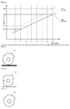
Fig. 4] Fig. 4 is a graph showing a relationship between a detection signal and an output signal of the embodiment. - [
Fig. 5] Fig. 5 is a side view of a displacement member of another embodiment of the present invention. - [
Fig. 6] Fig. 6 is a side view of a displacement member of a further embodiment of the present invention. - [
Fig. 7] Fig. 7 is a side view of a displacement member of a furthermore embodiment of the present invention. - Hereinafter, an embodiment of the present invention will be described with reference to the accompanying drawings.
- A shift position detection device 1 of the embodiment of the present invention detects a shift position of a transmission of a vehicle such as a bicycle, and is mainly composed of a
position detection device 2 and a gauging device 3. It is to be noted that reference numeral 4 designates a cam which is displacement member and is metallic. In the case of bicycle, the cam 4 is rotated by operation of a shifting pedal operated by a driver of the vehicle, and is intended to rotate with a change of the shift position. The cam 4 has a different distance from a rotational center to an outer circumference. Utilizing the different distance from the rotational center to the outer circumference, an outer circumference of the cam 4 corresponds to the shift position. In the embodiment, a first shift of the transmission is assigned to a portion at which the distance from the rotational center to the outer circumference is the shortest, a neutral shift is assigned to a portion at which the distance is short, and a second shift and a third shift are assigned to their appropriate portions. It is to be noted that, inFig. 1 , although numerals and alphabetical letters are assigned to the outer circumference of the cam 4, these numerals and alphabetical letters are added for the sake of description of the embodiment.Reference numeral 5 designates a casing to house the transmission of the vehicle, and theposition detection device 2 is fixed. - The
position detection device 2 is intended to convert, to an electrical signal, a distance from the cam 4 that is rotated by operation of the shifting pedal of a gear which is operated by the driver of the vehicle and then output the converted electrical signal to the gauging device 3. - The
position detection device 2 is composed of: ashaft 21 which is a moving body; amagnet 22; amagnetism detection unit 23; acircuit board 24; acord 25; ahousing 26; and aspring 27. - The
shaft 21 is a metallic rod-like member, comes into contact with the outer circumference of the cam 4, and is intended to convert a rotational movement of the cam 4 to a linear movement. Theshaft 21 is always pushed against the cam 4 by way of thespring 27. - The
magnet 22 is fixed to theshaft 21, and is intended to be displaced together with theshaft 21. - The
magnetism detection unit 23 is intended to detect a change in magnetic field exerted by the displacement of themagnet 22 and then output a detection signal based on a movement quantity of themagnet 22.Fig. 3 is a block diagram showing an electrical configuration of themagnetism detection unit 23 that is composed of amagnetism detection element 23a, acontrol unit 23b, and anoutput unit 23c. - The
magnetism detection element 23a is made of a Hall effect device or a magnetic resistance effect element or the like, and is intended to detect a magnetic field vector associated with a position of themagnet 22 and then outputs a detection signal to thecontrol unit 23b. - The
control unit 23b is provided with: aCPU 23d which is a computing unit; a read-only memory (hereinafter, referred to as a ROM) 23e which is a rewriting-disable storage unit; a random access memory (hereinafter, referred to as a RAM) 23f which is a temporary storage unit used at the time of computation of theCPU 23d; and anEEPROM 23g which is a rewritable nonvolatile storage unit. - In the
ROM 23e, programs or the like to drive themagnetism detection element 23a are stored. TheRAM 23f is intended to temporarily store variables or the like utilized by the programs. TheEEPROM 23g stores in advance information related to the detection signal and the output signal that are associated with the position of themagnet 22 detected by themagnetism detection element 23a, that is, magnetism position information relative to a magnetic field vector of the magnet. TheCPU 23d refers to theEEPROM 23g, and converts the magnetic field vector that is detected by themagnetism detection element 23a, to the position of the magnet 12. - The
output unit 23c outputs an output signal based on the position of themagnet 22 computed by theCPU 23d. - The
circuit board 24 is made of a hard insulation material, and is provided with an electrically conductive pattern which is not shown. On thecircuit board 24, themagnetism detection element 23 and thecord 25 are implemented. - The
cord 25 is intended to electrically connect thecircuit board 24 and the gauging device 3 to each other. In the embodiment, although thecord 25 is obtained by covering an electrically conductive material with an insulation material, this cord may be a metallic lead as long as it is possible to output an output signal to an external device such as the gauging device 3. - The
housing 26 is intended to house theshaft 21, themagnet 22, themagnetism detection element 23, thecircuit board 24, and thecord 25 or the like, and is metallic in the embodiment. Thehousing 26 is provided with ascrew part 26a, and is fixed to acasing 5 by way of thescrew part 26a. - The gauging device 3 is composed of a
control device 31, adisplay device 32, and external input means 33. - The
control device 31 is provided with: aCPU 31a which is a computing unit; a read-only memory (hereinafter, referred to as a ROM) 31b which is a non-rewritable storage unit; a random access memory (hereinafter, referred to as a RAM) 31c which is a temporary storage unit used at the time of computation of theCPU 31a; and anEEPROM 31d which is a rewritable nonvolatile storage unit. - In the
ROM 31b, programs or the like to drive the gauging device 3 are stored. TheRAM 31c is intended to temporarily store variables or the like utilized by the programs. The EEPROM 31d stores information as to a detection signal associated with the position of themagnet 22 output by themagnetism detection unit 23 and information as to an output signal which is display information displayed by thedisplay device 32 on the basis of the detection signal. That is, an output signal to thedisplay device 32 relative to the detection information that is output from themagnetism detection unit 23 is stored in advance. TheCPU 31a refers to theEEPROM 31d, and converts the detection signal that is output by themagnetism detection unit 23, to an output signal of thedisplay device 32. - The
display device 32 is a device which is composed of a liquid crystal display element or an organic light emitting diode display element, or alternatively, a plurality of light sources, and is capable of displaying at least a shift position in the embodiment. - The external input means 33 is operating means of the gauging device 3, and for example, is a trip knob to reset the number of measurements of a distance gauge such as a trip meter. This external input means 33 is used as a switch when the
control device 31 is changed from a normal mode to a correction mode in which the information stored in theEEPROM 31d is corrected or when the correction mode is changed to the normal mode. This external input means can also be used as a switch to rewrite the contents stored in theEEPROM 31d in thecontrol device 31. - Referring to
Fig. 5 , rewriting of information in theEEPROM 31d of the embodiment will be described. - In general, in so far as a distance between the
casing 5 and the cam 4 is concerned, a distortion occurs due to a dimensional error of each part and a positional error at the time of assembling. Due to this distortion of distance, in so far as the output signal of theposition detection device 2 relative to the position of the cam 4 is concerned, an error occurs to an intended output signal at an initial stage of designing, and there occurs a problem that a precise position of the cam 4 cannot be detected. That is, as a detection signal before rewritten, in a relationship with an output signal, at the time of a detection signal P1 before rewritten, an neutral output signal has been output; and however, due to the error at the time of assembling mentioned above, in the case of the detection signal after rewritten and the output signal, shown inFig. 4 , in so far as the detection signal P1 is concerned, an output signal as the second shift is output, and the precise position of the cam 4 could not be detected. - As another distortion, there is also a dimensional distortion of the cam 4 by the vehicle. Due to this dimensional distortion as well, in so far as the output signal of the
position detection device 2 relative to the position of the cam 4 is concerned, an error occurs to the intended output signal at the initial stage of designing, and there occurs the problem that the precise position of the cam 4 cannot be detected. - As still another distortion, due to contact between the cam 4 and the
shaft 21, due to friction of the cam 4 or theshaft 21, in so far as the output signal of theposition detection device 2 relative to the position of the cam 4 is concerned, an error occurs to the intended output signal at the initial stage of designing, and there occurs the problem that the precise position of the cam 4 cannot be detected. - Accordingly, in the embodiment, after the
position detection device 2 has been assembled to a vehicle body, or alternatively, after the elapse of a predetermined period of time subsequent to assembling, the information stored in theEEPROM 31d in thecontrol device 31 is rewritten in accordance with mounting to the vehicle, of theposition detection device 2, to be thereby able to detect the precise position of the cam 4 with a less significant error which is the intended output signal at the initial stage of designing. - Rewriting of the information that is stored in the
EEPROM 31d in thecontrol device 31 will be described below. - The
control device 31 migrate to a correction mode on the basis of a first operation (first input information) in which the external input means 32 has been operated. At this time, on thedisplay device 32, the correction mode is displayed. - Subsequent to the migration to the correction mode, the driver operates the position shifting pedal of the vehicle and then sets the gear of the position transmission to the neutral position. At this time, on the
display device 32, there may be displayed the fact that "the external input means 32 is operated after the gear of the position transmission has been selected to be neutral". In the embodiment, this neutral position is a first correction point, and in a state in which the gear of the position transmission of the vehicle has been set to be neutral at this first correction point (in a state in which a detection signal B1 has been output from the position detection device 2), on the basis of a second operation (second input information) in which the external input means 32 has been operated, the detection signal B1 of theposition detection device 2 is rewritten to information for determining the detection signal to be neutral. - Next, the driver operates the position shifting pedal of the vehicle, and sets the gear of the position transmission to the highest gear position (a seventh shift in the embodiment). At this time, on the
display device 32, there may be displayed the fact that "the external input means 32 is operated after the gear of the position transmission has been selected to be the seventh shift". In the embodiment, this position of the seventh shift is a second correction point, and in a state in which the gear of the position transmission of the vehicle has been set to the seventh shift at this second correction point (in a state in which a detection signal B2 has been output from the position detection device 2), on the basis of a third operation (third input information) in which the external input means 32 has been operated, the detection signal B2 of theposition detection device 2 is rewritten to information for determining the detection signal to be the seventh shift. Then, on the basis of a fourth operation (fourth input information) in which the external input means 32 has been operated, the correction mode migrates to the normal mode and rewriting of the information completes. At this time, on thedisplay device 32, there may be displayed the fact that the correction mode has migrated to the normal mode. Also, at the time of this mode migration, from the information as to two points of the neutral shift and the seventh shift, the information leading up to the first shift and the third to sixth shifts are estimated and then rewriting of the information is carried out. - As described above, the information as to the two points of the neutral shift and the seventh shift of the position transmission of the vehicle is rewritten, whereby the precise position of the
shaft 21 can be detected. - It is to be noted that, in the rewriting procedure mentioned hereinbefore, although the two points of the neutral shift and the seventh shift were exemplified, the correction points as a base for rewriting are not limited thereto, and each shift position may be a correction point.
- In view of the foregoing description, even in a case where an assembling error of the
position detection device 2 occurs or in a case where theshaft 21 has been worn, the errors as to the detection signal and the output signal can be rewritten and corrected, and it is possible to provide a shift position detection device that has excellent durability. Also, there is no need to provide a contact point for each detection point as in the conventional detection device, and it is possible to provide a shift position detection device that is capable of detecting many shift positions by detecting the displacement of theshaft 21. - It is to be noted that, although in the embodiment described hereinbefore, data as to the detection signal and the output signal was stored in the
EEPROM 31d provided in the gauging device 3, the data as to the detection signal and the output signal may be stored in theEEPROM 23g provided in theposition detection device 2 without being limited to the embodiment. - Also, the shape of the cam 4 is not limited to the shaft in which the outer circumference thereof is formed in a curved shape as in the embodiment, and the
cam 41 shown inFig. 5 may be acam 41 which has a different distance from the rotational center to the outer circumference, depending on the shift position, but which has an equal distance from the rotational center to the outer circumference corresponding to each shift position. - In addition, in so far as the shape of the cam is concerned, the distance from the rotational center to the outer circumference does not need to be long every time the number of speeds in position shifting increases, and the
cam 42 shown inFig. 6 may be formed in an irregular shape in which the distance from the rotational center to the outer circumference is long or short every time the number of speeds in position shifting increases. - Further, in so far as the shape of the cam is concerned, the distance from the rotational center to the outer circumference does not need to be long every time the number of speeds in position shifting increases, and the
cam 43 shown inFig. 7 may be short in the distance from the rotational center to the outer circumference every time the number of speeds in position shifting increases. - The present invention is applicable to a shift position detection device for detecting a shift position.
-
- 1
- Shift position detection device
- 2
- Position detection device
- 3
- Gauging device
- 4
- Displacement member (cam)
- 5
- Casing
- 21
- Moving body (shaft)
- 22
- Magnet
- 23
- Magnetism detection unit
- 23a
- Magnetism detection element
- 23b
- Control unit
- 23c
- Output unit
- 23d
- CPU
- 23e
- ROM
- 23f
- RAM
- 23g
- EEPROM
- 24
- Circuit board
- 25
- Cord
- 26
- Housing
- 26a
- Screw part
- 27
- Spring
- 31
- Control device
- 31a
- CPU
- 31b
- ROM
- 31c
- RAM
- 31d
- EEPROM
- 32
- Display device
- 33
- External input means
Claims (5)
- A shift position detection device comprising:a moving body that is displaced in contact with a displacement member displaced with a change of a shift position of a position transmission of a vehicle;a magnet that is displaced together with the moving body;a magnetism detection element that detects displacement of the magnet and then outputs a detection signal;a display device that displays a shift position on a basis of the detection signal of the magnetism detection element; anda control device that controls the display device on the basis of the detection signal,wherein a storage unit that stores an output signal that controls the display device on the basis of the detection signal of the magnetism detection element is provided, andwherein the output signal based on the detection signal, stored in the storage unit, can be rewritten.
- The shift position detection device according to claim 1, wherein the storage unit is provided in the control device.
- The shift position detection device according to claim 1, wherein the storage unit is provided in a magnetism detection unit comprising the magnetism detection element.
- The shift position detection device according to claim 1, wherein external input means that connects to the control device is provided, and by the external input means, the stored content that is stored in the storage unit is rewritten.
- The shift position detection device according to claim 4 , wherein the external input means is operating means of a gauging device provided in the vehicle.
Applications Claiming Priority (2)
| Application Number | Priority Date | Filing Date | Title |
|---|---|---|---|
| JP2013072098A JP6024566B2 (en) | 2013-03-29 | 2013-03-29 | Shift position detection device |
| PCT/JP2014/056330 WO2014156615A1 (en) | 2013-03-29 | 2014-03-11 | Shift position detection device |
Publications (2)
| Publication Number | Publication Date |
|---|---|
| EP2980524A1 true EP2980524A1 (en) | 2016-02-03 |
| EP2980524A4 EP2980524A4 (en) | 2016-11-23 |
Family
ID=51623598
Family Applications (1)
| Application Number | Title | Priority Date | Filing Date |
|---|---|---|---|
| EP14773150.9A Withdrawn EP2980524A4 (en) | 2013-03-29 | 2014-03-11 | Shift position detection device |
Country Status (5)
| Country | Link |
|---|---|
| US (1) | US20160041003A1 (en) |
| EP (1) | EP2980524A4 (en) |
| JP (1) | JP6024566B2 (en) |
| CN (1) | CN105102920A (en) |
| WO (1) | WO2014156615A1 (en) |
Cited By (1)
| Publication number | Priority date | Publication date | Assignee | Title |
|---|---|---|---|---|
| US20210387054A1 (en) * | 2020-06-16 | 2021-12-16 | Kristopher Schaefer | Apparatus and method for resistance calibration and digitization for exercise equipment |
Families Citing this family (2)
| Publication number | Priority date | Publication date | Assignee | Title |
|---|---|---|---|---|
| US20180172475A1 (en) * | 2015-06-11 | 2018-06-21 | Festo Ag & Co. Kg | Drive Device with Detection Apparatus and Method |
| US12235135B2 (en) * | 2021-04-12 | 2025-02-25 | Analog Devices International Unlimited Company | Magnetic sensor system with initialization mechanism |
Family Cites Families (19)
| Publication number | Priority date | Publication date | Assignee | Title |
|---|---|---|---|---|
| US4107604A (en) * | 1976-12-01 | 1978-08-15 | Compunetics, Incorporated | Hall effect displacement transducer using a bar magnet parallel to the plane of the Hall device |
| US4746772A (en) * | 1986-09-23 | 1988-05-24 | Fisher Controls International, Inc. | Adjustable position indicating apparatus |
| JP2570654B2 (en) * | 1987-12-08 | 1997-01-08 | 日本精工株式会社 | Displacement detector |
| DE4212319A1 (en) * | 1992-04-13 | 1993-10-14 | Fichtel & Sachs Ag | control device |
| DE4212320A1 (en) * | 1992-04-13 | 1993-10-14 | Fichtel & Sachs Ag | Electric actuator |
| JP2001304804A (en) * | 2000-04-25 | 2001-10-31 | Kayaba Ind Co Ltd | Steering angle detection mechanism of power steering device |
| JP3799270B2 (en) * | 2001-12-21 | 2006-07-19 | 株式会社日立製作所 | Control device for switching the driving state of an automobile |
| JP3934942B2 (en) | 2002-01-11 | 2007-06-20 | 朝日電装株式会社 | Shift position detector for motorcycles |
| JP2003307419A (en) * | 2002-04-15 | 2003-10-31 | Koyo Seiko Co Ltd | Rudder angle detector |
| JP4446377B2 (en) * | 2004-04-08 | 2010-04-07 | 株式会社小松製作所 | Displacement sensor |
| US20070068605A1 (en) * | 2005-09-23 | 2007-03-29 | U.I.T., Llc | Method of metal performance improvement and protection against degradation and suppression thereof by ultrasonic impact |
| JP4716499B2 (en) * | 2005-10-17 | 2011-07-06 | 株式会社小松製作所 | Pilot valve with lever position detection function |
| JP2007292674A (en) * | 2006-04-27 | 2007-11-08 | Hitachi Plant Technologies Ltd | Three-dimensional measurement method and apparatus |
| JP2009122047A (en) * | 2007-11-16 | 2009-06-04 | Ono Sokki Co Ltd | Angle detector |
| EP2166312B2 (en) * | 2008-09-18 | 2020-01-15 | Sick Ag | Magnetic or inductive waypoint sensor |
| CN101750008A (en) * | 2008-12-10 | 2010-06-23 | 涂成生 | Impulse sensor with damper for actively measuring linear displacement |
| JP2011149924A (en) * | 2009-09-29 | 2011-08-04 | Nippon Seiki Co Ltd | Variable-speed position detector |
| JP2014035210A (en) * | 2012-08-07 | 2014-02-24 | Tokai Rika Co Ltd | Rotation angle detection device |
| JP2014048156A (en) * | 2012-08-31 | 2014-03-17 | Nippon Seiki Co Ltd | Stroke sensor |
-
2013
- 2013-03-29 JP JP2013072098A patent/JP6024566B2/en not_active Expired - Fee Related
-
2014
- 2014-03-11 EP EP14773150.9A patent/EP2980524A4/en not_active Withdrawn
- 2014-03-11 WO PCT/JP2014/056330 patent/WO2014156615A1/en not_active Ceased
- 2014-03-11 CN CN201480018189.5A patent/CN105102920A/en active Pending
- 2014-03-11 US US14/780,999 patent/US20160041003A1/en not_active Abandoned
Cited By (1)
| Publication number | Priority date | Publication date | Assignee | Title |
|---|---|---|---|---|
| US20210387054A1 (en) * | 2020-06-16 | 2021-12-16 | Kristopher Schaefer | Apparatus and method for resistance calibration and digitization for exercise equipment |
Also Published As
| Publication number | Publication date |
|---|---|
| WO2014156615A1 (en) | 2014-10-02 |
| JP6024566B2 (en) | 2016-11-16 |
| CN105102920A (en) | 2015-11-25 |
| US20160041003A1 (en) | 2016-02-11 |
| EP2980524A4 (en) | 2016-11-23 |
| JP2014196929A (en) | 2014-10-16 |
Similar Documents
| Publication | Publication Date | Title |
|---|---|---|
| JP5931168B2 (en) | Angular and axial position sensor equipment | |
| EP2757439B1 (en) | Flexible display and method for measuring angle of the same | |
| US10976835B2 (en) | Operation input device | |
| US10310452B2 (en) | Timepiece comprising a wheel set with a determinable angular position | |
| JP4593910B2 (en) | Encoder | |
| US20160041003A1 (en) | Shift position detection device | |
| EP3379205A1 (en) | Motor control system, control method, encoder, and motor controller | |
| CN105180972B (en) | Linear transducer equipment for vehicle | |
| US12287250B2 (en) | Rotating multi-segment thin-film pressure sensor and arrangement method | |
| KR102376818B1 (en) | Auto Racing Footwear Motor with Rotary Drum Encoder | |
| US11782473B2 (en) | Inductive joystick | |
| US11041708B2 (en) | Angle sensing device | |
| US10809093B2 (en) | Rotation angle sensor system with variable measurement angle range | |
| JP5787161B2 (en) | Vehicle instrument | |
| JP5706355B2 (en) | Rotation angle detector | |
| KR101582529B1 (en) | The absolute encoder of counter type | |
| US12018961B2 (en) | Signaling device | |
| KR101898852B1 (en) | Potentiometers capable of self-diagnosing malfunction | |
| JP2015054671A (en) | Shifter control device | |
| JP2022074174A (en) | Rotation angle detecting device and rotation shifter | |
| KR102055799B1 (en) | Sensor for measuring stroke of pedal | |
| KR100721614B1 (en) | Measurement device and measurement method that extends the measurement range by using multiple sensors | |
| JP2006310080A (en) | Detection sensor | |
| JP2006311189A (en) | Detection sensor |
Legal Events
| Date | Code | Title | Description |
|---|---|---|---|
| PUAI | Public reference made under article 153(3) epc to a published international application that has entered the european phase |
Free format text: ORIGINAL CODE: 0009012 |
|
| 17P | Request for examination filed |
Effective date: 20151020 |
|
| AK | Designated contracting states |
Kind code of ref document: A1 Designated state(s): AL AT BE BG CH CY CZ DE DK EE ES FI FR GB GR HR HU IE IS IT LI LT LU LV MC MK MT NL NO PL PT RO RS SE SI SK SM TR |
|
| AX | Request for extension of the european patent |
Extension state: BA ME |
|
| DAX | Request for extension of the european patent (deleted) | ||
| A4 | Supplementary search report drawn up and despatched |
Effective date: 20161025 |
|
| RIC1 | Information provided on ipc code assigned before grant |
Ipc: G01D 5/12 20060101ALI20161019BHEP Ipc: G01D 5/14 20060101AFI20161019BHEP Ipc: G01B 5/00 20060101ALI20161019BHEP Ipc: G01B 7/00 20060101ALI20161019BHEP |
|
| STAA | Information on the status of an ep patent application or granted ep patent |
Free format text: STATUS: THE APPLICATION HAS BEEN WITHDRAWN |
|
| 18W | Application withdrawn |
Effective date: 20170125 |
|
| RIN1 | Information on inventor provided before grant (corrected) |
Inventor name: HAYAKAWA, TOSHIO |