EP2980513A1 - Kühlgutablage für ein kältegerät - Google Patents
Kühlgutablage für ein kältegerät Download PDFInfo
- Publication number
- EP2980513A1 EP2980513A1 EP15178069.9A EP15178069A EP2980513A1 EP 2980513 A1 EP2980513 A1 EP 2980513A1 EP 15178069 A EP15178069 A EP 15178069A EP 2980513 A1 EP2980513 A1 EP 2980513A1
- Authority
- EP
- European Patent Office
- Prior art keywords
- refrigerated goods
- plate
- profile
- springs
- edge
- Prior art date
- Legal status (The legal status is an assumption and is not a legal conclusion. Google has not performed a legal analysis and makes no representation as to the accuracy of the status listed.)
- Granted
Links
Images


Classifications
-
- F—MECHANICAL ENGINEERING; LIGHTING; HEATING; WEAPONS; BLASTING
- F25—REFRIGERATION OR COOLING; COMBINED HEATING AND REFRIGERATION SYSTEMS; HEAT PUMP SYSTEMS; MANUFACTURE OR STORAGE OF ICE; LIQUEFACTION SOLIDIFICATION OF GASES
- F25D—REFRIGERATORS; COLD ROOMS; ICE-BOXES; COOLING OR FREEZING APPARATUS NOT OTHERWISE PROVIDED FOR
- F25D25/00—Charging, supporting, and discharging the articles to be cooled
- F25D25/02—Charging, supporting, and discharging the articles to be cooled by shelves
-
- F—MECHANICAL ENGINEERING; LIGHTING; HEATING; WEAPONS; BLASTING
- F25—REFRIGERATION OR COOLING; COMBINED HEATING AND REFRIGERATION SYSTEMS; HEAT PUMP SYSTEMS; MANUFACTURE OR STORAGE OF ICE; LIQUEFACTION SOLIDIFICATION OF GASES
- F25D—REFRIGERATORS; COLD ROOMS; ICE-BOXES; COOLING OR FREEZING APPARATUS NOT OTHERWISE PROVIDED FOR
- F25D2325/00—Charging, supporting or discharging the articles to be cooled, not provided for in other groups of this subclass
- F25D2325/022—Shelves made of glass or ceramic
Definitions
- the present invention relates to a refrigerated goods storage for a refrigeration appliance, in particular a household refrigeration appliance such as a refrigerator.
- Refrigerated goods trays are used to divide the storage space inside a refrigerator into several superimposed compartments.
- the storage space is limited by an inner container that is molded in one piece from plastic.
- the manufacturing accuracy during deep drawing is relatively low, so that the dimensions of the finished inner container can fluctuate significantly.
- the width of an inner container so that a mold used for deep drawing can be easily pulled out of the finished inner container after completion of the deep drawing, from the open front to the rear wall of the inner container to decrease.
- the width of a refrigerated goods deposit to be used in such a refrigerator with a deep-drawn inner container therefore has to be small enough to fit into the inner container even if it is narrow. If the inner container has failed normal or wide, then the chilled goods shelf is movable in the transverse direction, which can lead to disturbing rattling noises and to abrasion on the inner container or the(7)gutablage.
- EP 0 582 784 A1 proposes to provide for fixing a refrigerated goods storage in the inner container of a refrigerator adapter, which are anchored in receptacles on a side wall of the inner container by engagement of a pin and having a projecting from the wall support surface which engages by engaging in a recess ofmégutablage, this one supported, on the other hand fixed in the depth direction of the inner container.
- the adapters further comprise a spring that is deflectable sideways in contact with the edge of a refrigerated goods deposit, against the inner container wall.
- the object is achieved by arranging at least one pair of elastically compressible springs in the lateral direction at a refrigerated goods deposit for a refrigerator with a lateral edge, a front and a rear edge having plate on the lateral edges of the plate.
- edges of the refrigerated goods deposit can be formed by a frame enclosing the plate, in particular from an impact-resistant plastic.
- the springs can then expediently form part of this frame.
- the frame can be integrally formed directly on the plate, in particular molded. More rational, especially with regard to the production of refrigerated goods trays in different dimensions, however, is to assemble the frame of several, each along an edge of the plate extending profiles.
- the springs can then be conveniently formed integrally with one and the same of these profiles or with two different profiles.
- the springs of the first pair are preferably arranged adjacent to the front edge.
- the inner container In adaptation to the shape of the inner container that is a front profile, which forms a front edge of the refrigerated goods storage, preferably longer than a rear edge of the refrigerated goods storage.
- the rear edge can in turn be formed by a profile; but it is also a structure into consideration, in which the plate is bordered only at the front and side of profiles and the rear edge of the refrigerated goods tray is the rear edge of the plate itself.
- the front profile may have at its ends recesses in which the springs are arranged and which are bounded at least forwards and upwards by a respective wall.
- the two springs of the first pair are integrally formed with the profile forming the front edge of the refrigerated goods deposit.
- this front profile can be latched to two side profiles.
- At least the two lateral profiles should have a groove which receives an edge of the plate.
- a groove may also be provided on the front profile.
- the grooves of the lateral profiles may be closed at their rear end to secure the plate securely.
- a second pair of elastically compressible springs in the lateral direction may be arranged adjacent to the rear edge of the refrigerated goods storage.
- the springs of this second pair are preferably each formed integrally with a lateral profile.
- Fig. 1 shows in section a deep drawn from a plastic plate inner container 1, which is provided to be installed in a conventional manner in a body of a refrigerator housing.
- a refrigerated goods tray 2 On side walls of the inner container 1 supporting ribs 3 are formed, on which a refrigerated goods tray 2 rests.
- the refrigerated goods deposit 2 comprises a flat plate 4, preferably made of safety glass, which is bordered by a frame 30 at least along some of its four edges for stabilization and protection against damage.
- the frame 30 is here composed of a plurality of injection-molded profiles in one piece plastic.
- a front profile 5 is attached to a front edge 25 of the plate 4, and lateral profiles 6 (of which in Fig.
- Fig. 2 shows thedegutablage 2 in an exploded perspective view, wherein in the installed state of Fig. 1 turned down side in the representation of Fig. 2 turned upwards.
- the front profile 5 and the side profiles 6 are respectively opposite the edges 25, 32 of the plate 4 opposite to which they are to be plugged.
- a locking projection 33 can be seen in each case, which engages in a recess of the support ribs 3 when the refrigerated goods tray 2 is installed in the inner container 1 and so the refrigerated goods tray 2 immovably locked in the depth direction of the inner container 1.
- a rib 34 is formed, which can serve as a guide for a non-illustrated, resting on the refrigerated goods tray 2 pull-out box.
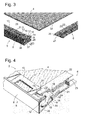
- Fig. 3 shows in the same perspective as Fig. 2 and on an enlarged scale, a front corner of the refrigerated goods storage 2. To see are each a part of the plate 4, the front profile 5 and one of the two side profiles. 6
- the front profile 5 comprises a vertically oriented, in the assembled state of the Fig. 1 the open front side of the inner container 1 facing end 8 and from this outgoing horizontal leg 9, 10.
- the horizontal leg 9, 10 define a groove which receives the front edge 25 of the plate 4.
- this groove is denoted by 11, in Fig. 3 it is not directly visible, since it is closed in the lateral direction by the two legs 9, 10 interconnecting walls 12. Only through window 31 in (in the perspective of Fig. 3 ) upper leg 10 through a piece of the leg 9 can be seen on the opposite side of the groove 11.
- both longitudinal ends 35 of the profile 5 define the walls 12 together with over it laterally projecting end portions 36, 37 of the front side 8 and the horizontal leg 9 at each end of the front profile 5 a recess 13, the side and, in the mounted position of the Fig. 1 , is open to the bottom.
- a recess 13 projects from the wall 12 in extension of the horizontal leg 10 a Projection 14 into it.
- At its end face 8 facing flank of this projection 14 is in a gently curved, over a lateral end edge 26 of the leg 9 projecting spring 15.
- a guide wedge 16 on a rear edge 17 of the horizontal leg 10 addition towards the rear, which serves the toothing with the lateral profile 6.
- a latching recess or a latching window 19 is recessed on the horizontal leg 10.
- the lateral profile 6 also comprises two horizontal legs 21, 22, which are connected to one another by a wall 23 and form a groove which receives the lateral edge 32 of the plate 4.
- a barb 20 is formed on the level with the horizontal leg 10 of the front profile 5 legs 54 of the lateral profile 6 to in Fig. 4 shown state in which the profiles 5, 6 are attached to the plate 4, to engage in the locking window 19.
- the leg 21 is in the perspective of Fig. 4 largely hidden behind leg 22 and wall 23, can be seen a part of the leg 21 which projects in a lateral direction beyond the wall 23 to support the refrigerated goods tray 2 on one of the support ribs 3.
- the leg 22 carries at its outer edge a vertical plate 24 which, together with the opposite wall 23 defines a wedge-shaped rearwardly tapering guide recess 18 which receives the guide wedge 16.
- the front profile 5 is pushed onto the plate 4 and the laterally infected profiles 6, first the front edge 25 of the plate 4 moves into the groove 11 of the profile 5.
- the lower horizontal leg 10 abuts against the tip of the barb 20, the profile 5 vertically immovably connected to the plate 4, so that the barb 20 is elastically deflected down and slides on the leg 10.
- the guide wedge 16 While the leg 10 is clamped between the barb 20 and the plate 4, the guide wedge 16 enters the guide recess 18 of the side profile 6 and thus forces in the width direction of the refrigerated goods tray 2 alignment of the profiles 5, 6 to each other, in which, when Barb 20 reaches the latching window 19 and engages therein, by contact of the guide wedge 16 with both the wall 23 and with the plate 24, the lateral profile 6 is positioned substantially free of play in the width direction and the plate 24 under acute angle extending to the depth direction of the refrigerated goods shelf extending end edge 26 of the leg 9 flush.
- An edge 27 of the latching window 19, on which as in Fig. 5 shown the barb 20 attacks, (or the edge 27 opposite flank of the barb 20) may be slightly inclined, so that when the profiles 5, 6 abut each other, the barb 20 presses against the edge 27, without losing its relaxed position to have reached again, and so the profiles 5, 6 pressed against each other. So the profiles 5 and 6 are held together firmly and without play.
- the projection of the spring 15 in the lateral direction over the end edge 26 of the leg 9 corresponds to at least half the width tolerance of the inner container 1.
- a rear profile could be plugged onto the rear edge 7 of the plate 4 and locked in a similar manner as shown above for the front profile 5 on the side profiles 6 to fix the plate all around.
- a rear profile is missing, instead the lateral profiles 6 are here at their rear end, as in the right part of FIG Fig. 5 to be closed by a wall 28, so that the plate 4 is held immovably between this wall 28 and the end face 8 of the front profile 5 substantially in the depth direction.
- the wall 28 may also be absent if the distance between the rear edge 7 and the rear wall of the inner container 1 in the mounted state is small enough to preclude escape of the plate 4 from the groove 11 of the front profile 5.
- Fig. 6 shows a perspective view of a rear corner of the refrigerated goods tray 2 according to a modified embodiment.
- One of the wall 23 of the lateral profile 6 laterally projecting - here partially in a recess 38 of the wall 23 recorded - spring 29 is in the assembled state in contact with the side wall of the Inner container 1 elastically deformed.
- the front springs 15 can relax by the refrigerated goods deposit 2 rotating about a vertical axis and the front profile 5 deviating from the transverse direction of the inner container 1 Orientation takes.
Landscapes
- Engineering & Computer Science (AREA)
- Chemical & Material Sciences (AREA)
- Combustion & Propulsion (AREA)
- Physics & Mathematics (AREA)
- Mechanical Engineering (AREA)
- Thermal Sciences (AREA)
- General Engineering & Computer Science (AREA)
- Devices That Are Associated With Refrigeration Equipment (AREA)
- Freezers Or Refrigerated Showcases (AREA)
- Refrigerator Housings (AREA)
Description
- Die vorliegende Erfindung betrifft eine Kühlgutablage für ein Kältegerät, insbesondere ein Haushaltskältegerät wie etwa einen Kühlschrank.
- Kühlgutablagen werden eingesetzt, um den Lagerraum im Innern eines Kühlschranks in mehrere übereinanderliegende Fächer zu unterteilen. Bei den meisten gegenwärtig auf dem Markt verbreiteten Kühlschränken ist der Lagerraum durch einen Innenbehälter begrenzt, der aus Kunststoff einteilig tiefgezogen ist. Die Fertigungsgenauigkeit beim Tiefziehen ist relativ gering, so dass die Abmessungen der fertigen Innenbehälter deutlich fluktuieren können. Außerdem muss die Breite eines Innenbehälters, damit ein zum Tiefziehen verwendetes Formwerkzeug nach Abschluss des Tiefziehens aus dem fertigen Innenbehälter problemlos herausgezogen werden kann, von der offenen Vorderseite zur Rückwand des Innenbehälters hin abnehmen. Die Breite einer in einem solchen Kältegerät mit tiefgezogenem Innenbehälter zu verwendenden Kühlgutablage muss daher klein genug sein, um auch dann in den Innenbehälter hinein zu passen, wenn dieser schmal ausgefallen ist. Wenn der Innenbehälter normal oder breit ausgefallen ist, dann ist die Kühlgutablage darin in Querrichtung beweglich, was zu störenden Klappergeräuschen und zu Abrieb am Innenbehälter oder der Kühlgutablage führen kann.
-
EP 0 582 784 A1 schlägt vor, zur Fixierung einer Kühlgutablage im Innenbehälter eines Kältegeräts Adapter vorzusehen, die in Aufnahmen an einer Seitenwand des Innenbehälters durch Eingriff eines Zapfens verankert sind und eine von der Wand abstehende Tragfläche aufweisen, die, indem sie in eine Aussparung der Kühlgutablage eingreift, diese zum einen unterstützt, zum anderen in Tiefenrichtung des Innenbehälters fixiert. Die Adapter umfassen ferner eine Feder, die in Kontakt mit dem Rand einer Kühlgutablage seitwärts, gegen die Innenbehälterwand, auslenkbar ist. Mithilfe einer solchen Feder ist es zwar grundsätzlich möglich, die Kühlgutablage trotz eventueller Toleranzen der Breite des Innenbehälters spielfrei zu zentrieren, doch muss die Feder um so länger sein, je größer die auszugleichende Toleranz ist, und um so größer und auffälliger wird folglich auch der Adapter. Außerdem erhöhen die Adapter den Aufwand beim Zusammenbau des Geräts und machen es mühsam, die Einbauhöhe einer Kühlgutablage im Innenbehälter zu ändern, da sie zusammen mit der Kühlgutablage versetzt werden müssen. - Aus
EP 1 929 223 A1 ist eine Kühlgutablage für ein Kältegerät bekannt geworden, bei der eine vertikal auslenkbare Blattfeder das hintere Ende eines seitlichen Randes der Kühlgutablage bildet. Diese Blattfeder dient zur formschlüssigen, lösbaren Verrastung der Kühlgutablage in einer Nut der Seitenwand des Innenbehälters; einen Ausgleich von Fertigungstoleranzen des Innenbehälters erlaubt sie nicht. - Eine Aufgabe der vorliegenden Erfindung ist, eine Kühlgutablage zu schaffen, die in einem Innenbehälter eines Kältegeräts trotz eventuell streuender Breite des Innenbehälters sicher und unbeweglich montierbar ist.
- Die Aufgabe wird gelöst, indem bei einer Kühlgutablage für ein Kältegerät mit einer seitliche Kanten, eine vordere und eine hintere Kante aufweisenden Platte an den seitlichen Kanten der Platte wenigstens ein Paar von in seitlicher Richtung elastisch stauchbaren Federn angeordnet ist.
- Um die Platte, insbesondere wenn diese aus Glas gefertigt ist, vor Stößen auf ihre Kanten zu schützen, können Ränder der Kühlgutablage durch einen die Platte einfassenden Rahmen, insbesondere aus einem schlagzähen Kunststoff, gebildet sein.
- Die Federn können dann zweckmäßigerweise einen Teil dieses Rahmens bilden.
- Der Rahmen kann unmittelbar an die Platte einteilig angeformt, insbesondere angespritzt werden. Rationeller, insbesondere im Hinblick auf die Fertigung von Kühlgutablagen in unterschiedlichen Abmessungen, ist jedoch, den Rahmen aus mehreren, sich jeweils entlang einer Kante der Platte erstreckenden Profilen zusammenzusetzen.
- Die Federn können dann zweckmäßigerweise einteilig mit ein und demselben dieser Profile oder mit zwei verschiedenen Profilen geformt sein.
- Um die Kühlgutablage in einem in fachüblicher Weise nach hinten schmaler werdenden Innenbehälter zu stabilisieren, sind die Federn des ersten Paars sind vorzugsweise benachbart zur vorderen Kante angeordnet.
- In Anpassung an die Form des Innenbehälters ist das ein vorderes Profil, das einen vorderen Rand der Kühlgutablage bildet, vorzugsweise länger als ein hinterer Rand der Kühlgutablage.
- Der hintere Rand kann seinerseits wiederum durch ein Profil gebildet sein; es kommt aber auch ein Aufbau in Betracht, bei dem die Platte lediglich vorn und seitlich von Profilen eingefasst ist und der hintere Rand der Kühlgutablage die hintere Kante der Platte selber ist.
- Um eine unauffällige Anbringung der Federn zu ermöglichen, kann das vordere Profil an seinen Enden Aussparungen aufweisen, in denen die Federn angeordnet sind und die wenigstens nach vorn und nach oben jeweils durch eine Wand begrenzt sind.
- Vorzugsweise sind die beiden Federn des ersten Paars einteilig mit dem den vorderen Rand der Kühlgutablage bildenden Profil geformt.
- Um den Rahmen zu bilden, kann dieses vordere Profil an zwei seitlichen Profilen verrastet sein.
- Um die Platte sicher zu fixieren, sollten wenigstens die beiden seitlichen Profile eine Nut aufweisen, die eine Kante der Platte aufnimmt. Zusätzlich kann eine solche Nut auch an dem vorderen Profil vorgesehen sein.
- Insbesondere wenn die hintere Kante der Platte freiliegt, ohne von einem Profil des Rahmens eingefasst zu sein, können die Nuten der seitlichen Profile an ihrem hinteren Ende geschlossen sein, um die Platte sicher zu fixieren.
- Ein zweites Paar von in seitlicher Richtung elastisch stauchbaren Federn kann benachbart zum hinteren Rand der Kühlgutablage angeordnet sein.
- Die Federn dieses zweiten Paars sind vorzugsweise jeweils einteilig mit einem seitlichen Profil geformt.
- Weitere Merkmale und Vorteile der Erfindung ergeben sich aus der nachfolgenden Beschreibung von Ausführungsbeispielen unter Bezugnahme auf die beigefügten Figuren. Es zeigen:
- Fig. 1
- einen schematischen Schnitt durch den Innenbehälter eines Kältegeräts und eine in dem Innenbehälter angeordnete Kühlgutablage gemäß der vorliegenden Erfindung;
- Fig. 2
- eine auseinandergezogene Darstellung der Kühlgutablage;
- Fig. 3
- eine vergrößerte perspektivische Ansicht einer vorderen Ecke der Kühlgutablage;
- Fig. 4
- die Ecke der
Fig. 3 im zusammengefügten Zustand - Fig. 5
- einen Schnitt durch die vordere Ecke der Kühlgutablage aus
Fig. 4 in Tiefenrichtung; und - Fig. 6
- eine hintere Ecke der Kühlgutablage in perspektivischer Ansicht.
-
Fig. 1 zeigt im Schnitt einen aus einer Kunststoffplatine tiefgezogenen Innenbehälter 1, der vorgesehen ist um in an sich bekannter Weise in einen Korpus eines Kältegerätegehäuses eingebaut zu werden. An Seitenwänden des Innenbehälters 1 sind Stützrippen 3 angeformt, auf denen eine Kühlgutablage 2 ruht. Die Kühlgutablage 2 umfasst eine ebene Platte 4, vorzugsweise aus Sicherheitsglas, die zur Stabilisierung und zum Schutz vor Beschädigung wenigstens entlang einiger ihrer vier Kanten von einem Rahmen 30 eingefasst ist. Der Rahmen 30 ist hier aus mehreren aus Kunststoff einteilig spritzgeformten Profilen zusammengesetzt. Im hier betrachteten Fall ist ein vorderes Profil 5 auf eine vordere Kante 25 der Platte 4 aufgesteckt, und seitliche Profile 6 (von denen inFig. 1 nur eines an der dem Betrachter zugewandten Seite der Kühlgutablage 2 sichtbar ist) umgreifen die seitlichen Kanten der Platte 4 und liegen auf den Stützrippen 3 auf. An einer hinteren Kante 7 der Platte 4 ist hier kein Profil gezeigt, doch könnte auch hier eines angebracht sein, um aus den Profilen einen sich rings um die Platte 4 erstreckenden Rahmen zu bilden. -
Fig. 2 zeigt die Kühlgutablage 2 in einer auseinandergezogenen perspektivischen Ansicht, wobei die im eingebauten Zustand derFig. 1 nach unten gewandte Seite in der Darstellung derFig. 2 nach oben gekehrt ist. Das vordere Profil 5 und die seitlichen Profile 6 sind jeweils den Kanten 25, 32 der Platte 4 gegenüberliegend dargestellt, auf die sie aufgesteckt werden sollen. An den dem Betrachter zugewandten Unterseiten der seitlichen Profile 6 ist jeweils ein Rastvorsprung 33 zu erkennen, der, wenn die Kühlgutablage 2 im Innenbehälter 1 eingebaut ist, in eine Aussparung der Stützrippen 3 eingreift und so die Kühlgutablage 2 in Tiefenrichtung des Innenbehälters 1 unbeweglich verrastet. An den Oberseiten der seitlichen Profile 6 ist eine Rippe 34 geformt, die als Führung für einen nicht dargestellten, auf der Kühlgutablage 2 ruhenden Auszugkasten dienen kann. -
Fig. 3 zeigt in derselben Perspektive wieFig. 2 und in vergrößertem Maßstab eine vordere Ecke der Kühlgutablage 2. Zu sehen sind jeweils ein Teil der Platte 4, des vorderen Profils 5 und eines der beiden seitlichen Profile 6. - Das vordere Profil 5 umfasst eine vertikal orientierte, im montierten Zustand der
Fig. 1 der offenen Vorderseite des Innenbehälters 1 zugewandte Stirnseite 8 und von dieser ausgehende horizontale Schenkel 9, 10. Die horizontalen Schenkel 9, 10 begrenzen eine Nut, die die vordere Kante 25 der Platte 4 aufnimmt. InFig. 5 ist diese Nut mit 11 bezeichnet, inFig. 3 ist sie nicht unmittelbar zu sehen, da sie in seitlicher Richtung durch die beiden Schenkel 9, 10 miteinander verbindende Wände 12 verschlossen ist. Lediglich durch Fenster 31 im (in der Perspektive vonFig. 3 ) oberen Schenkel 10 hindurch ist ein Stück des Schenkels 9 an der gegenüberliegenden Seite der Nut 11 zu sehen. - An beiden Längsenden 35 des Profils 5 begrenzen die Wände 12 zusammen mit über sie seitwärts überstehenden Endabschnitten 36, 37 der Stirnseite 8 und des horizontalen Schenkels 9 an jedem Ende des vorderen Profils 5 eine Aussparung 13, die zur Seite sowie, in der montierten Stellung der
Fig. 1 , nach unten offen ist. In diese Aussparung 13 ragt ausgehend von der Wand 12 in Verlängerung des horizontalen Schenkels 10 ein Vorsprung 14 hinein. An seiner der Stirnseite 8 zugewandten Flanke geht dieser Vorsprung 14 über in eine sanft geschwungene, über eine seitliche Endkante 26 des Schenkels 9 überstehende Feder 15. An der gegenüberliegenden Flanke des Vorsprungs 14 steht ein Führungskeil 16 über eine rückwärtige Kante 17 des horizontalen Schenkels 10 hinaus nach hinten vor, der der Verzahnung mit dem seitliche Profil 6 dient. - Benachbart zur Wand 12 ist am horizontalen Schenkel 10 eine Rastaussparung oder ein Rastfenster 19 ausgespart.
- Wie das vordere Profil 5 umfasst auch das seitliche Profil 6 zwei horizontale Schenkel 21, 22, die durch eine Wand 23 miteinander verbunden sind und eine die seitliche Kante 32 der Platte 4 aufnehmende Nut bilden. Ein Widerhaken 20 ist an den mit dem horizontalen Schenkel 10 des vorderen Profils 5 niveaugleichen Schenkel 22 des seitlichen Profils 6 angeformt, um in
Fig. 4 gezeigten Zustand, in dem die Profile 5, 6 auf die Platte 4 aufgesteckt sind, in das Rastfenster 19 einzugreifen. Der Schenkel 21 ist in der Perspektive derFig. 4 großenteils hinter Schenkel 22 und Wand 23 verborgen, zu sehen ist ein Teil des Schenkels 21, der in seitlicher Richtung über die Wand 23 hinaus vorspringt, um die Kühlgutablage 2 auf einer der Stützrippen 3 abzustützen. An seinem vorderen Ende trägt der Schenkel 22 an seiner äußeren Kante eine vertikale Platte 24, die zusammen mit der gegenüberliegenden Wand 23 eine sich keilförmig nach hinten verjüngende Führungsaussparung 18 begrenzt, die den Führungskeil 16 aufnimmt. - Wenn beim Zusammenfügen der Kühlgutablage 2 das vordere Profil 5 auf die Platte 4 und die seitlich daran angesteckten Profile 6 aufgeschoben wird, rückt zunächst die vordere Kante 25 der Platte 4 in die Nut 11 des Profils 5 ein. Dadurch ist, wenn kurz darauf der untere horizontale Schenkel 10 gegen die Spitze des Widerhakens 20 stößt, das Profil 5 vertikal unbeweglich mit der Platte 4 verbunden, so dass der Widerhaken 20 elastisch nach unten ausgelenkt wird und auf den Schenkel 10 gleitet. Während der Schenkel 10 zwischen dem Widerhaken 20 und der Platte 4 geklemmt ist, tritt der Führungskeil 16 in die Führungsaussparung 18 des seitlichen Profils 6 ein und erzwingt so in Breitenrichtung der Kühlgutablage 2 eine Ausrichtung der Profile 5, 6 zueinander, bei der, wenn der Widerhaken 20 das Rastfenster 19 erreicht und darin einrückt, durch Kontakt des Führungskeils 16 sowohl mit der Wand 23 als auch mit der Platte 24 das seitliche Profil 6 in Breitenrichtung im Wesentlichen spielfrei positioniert ist und die Platte 24 die unter spitzem Winkel zur Tiefenrichtung der Kühlgutablage verlaufende Endkante 26 des Schenkels 9 bündig verlängert.
- Ein Rand 27 des Rastfensters 19, an dem wie in
Fig. 5 gezeigt der Widerhaken 20 angreift, (oder eine dem Rand 27 gegenüberliegende Flanke des Widerhakens 20) kann leicht schräg ausgerichtet sein, so dass, wenn die Profile 5, 6 aneinander stoßen, der Widerhaken 20 gegen den Rand 27 drückt, ohne dabei seine entspannte Stellung wieder erreicht zu haben, und so die Profile 5, 6 gegeneinander gedrückt hält. So sind die Profile 5 und 6 fest und ohne Spiel zusammengehalten. - Der Überstand der Feder 15 in seitlicher Richtung über Endkante 26 des Schenkels 9 entspricht mindestens der halben Breitentoleranz des Innenbehälters 1. So kann sichergestellt werden, dass, wenn die Breite des Innenbehälters 1 innerhalb der Toleranz minimal ist, das Profil 5 dennoch zwischen den Seitenwänden des Innenbehälters 1 Platz findet, und dass auch bei maximaler Breite des Innenbehälters die Federn 15 an beiden Enden des Profils 5 noch in Kontakt mit den Seitenwänden des Innenbehälters 1 elastisch ausgelenkt sind, um die Kühlgutablage 2 zwischen den Seitenwänden zu zentrieren und festzuhalten.
- Ein hinteres Profil könnte auf die rückwärtige Kante 7 der Platte 4 aufgesteckt und in ähnlicher Weise wie oben für das vordere Profil 5 gezeigt an den seitlichen Profilen 6 verrastet sein, um die Platte ringsum zu fixieren. Bei der hier gezeigten Ausgestaltung fehlt ein solches hinteres Profil, stattdessen sind die seitlichen Profile 6 hier an ihrem rückwärtigen Ende, wie im rechten Teil von
Fig. 5 zu erkennen, durch eine Wand 28 verschlossen, so dass die Platte 4 zwischen dieser Wand 28 und der Stirnseite 8 des vorderen Profils 5 im Wesentlichen in Tiefenrichtung unbeweglich gehalten ist. Die Wand 28 kann auch fehlen, wenn der Abstand zwischen der rückwärtigen Kante 7 und der Rückwand des Innenbehälters 1 im montierten Zustand klein genug ist, um ein Entweichen der Platte 4 aus der Nut 11 des vorderen Profils 5 auszuschließen. -
Fig. 6 zeigt in perspektivischer Ansicht eine hintere Ecke der Kühlgutablage 2 gemäß einer abgewandelten Ausgestaltung. Eine von der Wand 23 des seitlichen Profils 6 seitwärts überstehende - hier zum Teil in einer Aussparung 38 der Wand 23 aufgenommene - Feder 29 ist im montierten Zustand im Kontakt mit der Seitenwand des Innenbehälters 1 elastisch verformt. Indem somit die Kühlgutablage 2 an vier Punkten über Federn 15, 29 abgestützt ist, ist ausgeschlossen, dass sich die vorderen Federn 15 entspannen können, indem die Kühlgutablage 2 um eine vertikale Achse rotiert und das vordere Profil 5 eine von der Querrichtung des Innenbehälters 1 abweichende Orientierung einnimmt. -
- 1
- Innenbehälter
- 2
- Kühlgutablage
- 3
- Stützrippe
- 4
- Platte
- 5
- vorderes Profil
- 6
- seitliches Profil
- 7
- hintere Kante
- 8
- Stirnseite
- 9
- Schenkel
- 10
- Schenkel
- 11
- Nut
- 12
- Wand
- 13
- Aussparung
- 14
- Vorsprung
- 15
- Feder
- 16
- Führungskeil
- 17
- rückwärtige Kante
- 18
- Führungsaussparung
- 19
- Rastfenster
- 20
- Widerhaken
- 21
- Schenkel
- 22
- Schenkel
- 23
- Wand
- 24
- Platte
- 25
- vordere Kante
- 26
- Endkante
- 27
- Rand
- 28
- Wand
- 29
- Feder
- 30
- Rahmen
- 31
- Fenster
- 32
- seitliche Kante
- 33
- Rastvorsprung
- 34
- Rippe
- 35
- Längsende
- 36
- Endabschnitt
- 37
- Endabschnitt
- 38
- Aussparung
Claims (14)
- Kühlgutablage (2) für ein Kältegerät mit seitlichen Kanten (32), eine vordere und eine hintere Kante (25, 7) aufweisenden Platte (4), dadurch gekennzeichnet, dass an den seitlichen Kanten (32) der Platte (4) wenigstens ein Paar von in seitlicher Richtung elastisch stauchbaren Federn (15, 29) angeordnet ist.
- Kühlgutablage nach Anspruch 1, dadurch gekennzeichnet, dass Kanten der Kühlgutablage (2) durch einen die Platte (4) einfassenden Rahmen (30) gebildet sind.
- Kühlgutablage nach Anspruch 2, dadurch gekennzeichnet, dass die Federn (15, 29) Teil des Rahmens (30) sind.
- Kühlgutablage nach Anspruch 2 oder 3, dadurch gekennzeichnet, dass der Rahmen (30) aus mehreren Profilen (5, 6) zusammengesetzt ist.
- Kühlgutablage nach Anspruch 4, dadurch gekennzeichnet, dass wenigstens eine der Federn (15; 29) einteilig mit einem der Profile (5; 6) geformt ist.
- Kühlgutablage nach einem der vorhergehenden Ansprüche, dadurch gekennzeichnet, dass die Federn (15) eines ersten Paars benachbart zur vorderen Kante (25) der Platte (4) angeordnet sind.
- Kühlgutablage nach einem der vorhergehenden Ansprüche, dadurch gekennzeichnet, dass ein vorderes Profil (5), das einen vorderen Rand der Kühlgutablage (2) bildet, länger als ein hinterer Rand (7) der Kühlgutablage (2) ist.
- Kühlgutablage nach Anspruch 7, dadurch gekennzeichnet, dass das vordere Profil (5) an seinen Längsenden (35) wenigstens nach vorn und nach oben durch eine Wand begrenzte Aussparungen (13) aufweist, in denen die Federn (15) angeordnet sind.
- Kühlgutablage nach einem der vorhergehenden Ansprüche, dadurch gekennzeichnet, dass die beide Federn (15) des ersten Paars einteilig mit einem einen vorderen Rand der Kühlgutablage (2) bildenden vorderen Profil (5) geformt sind.
- Kühlgutablage nach Anspruch 7, 8 oder 9, dadurch gekennzeichnet, dass das vordere Profil (5) an zwei seitlichen Profilen (6) verrastet ist.
- Kühlgutablage nach einem der vorhergehenden Ansprüche, dadurch gekennzeichnet, dass jedes Profil (5, 6) eine Nut (11) aufweist, die eine Kante (25, 32) der Platte (4) aufnimmt.
- Kühlgutablage nach Anspruch 11, dadurch gekennzeichnet, dass die seitlichen Profile (6) an ihrem hinteren Ende eine ihre Nut verschließende Wand (28) aufweisen.
- Kühlgutablage nach einem der vorhergehenden Ansprüche, dadurch gekennzeichnet, dass ein zweites Paar von in seitlicher Richtung elastisch stauchbaren Federn (29) benachbart zur hinteren Kante (7) angeordnet ist.
- Kühlgutablage nach Anspruch 13, dadurch gekennzeichnet, dass die Federn (29) des zweiten Paars jeweils einteilig mit einem seitlichen Profil (6) geformt sind.
Priority Applications (1)
| Application Number | Priority Date | Filing Date | Title |
|---|---|---|---|
| PL15178069T PL2980513T3 (pl) | 2014-07-29 | 2015-07-23 | Półka chłodnicza do urządzenia chłodniczego |
Applications Claiming Priority (1)
| Application Number | Priority Date | Filing Date | Title |
|---|---|---|---|
| DE102014214813.8A DE102014214813A1 (de) | 2014-07-29 | 2014-07-29 | Kühlgutablage für ein Kältegerät |
Publications (2)
| Publication Number | Publication Date |
|---|---|
| EP2980513A1 true EP2980513A1 (de) | 2016-02-03 |
| EP2980513B1 EP2980513B1 (de) | 2021-04-14 |
Family
ID=53773262
Family Applications (1)
| Application Number | Title | Priority Date | Filing Date |
|---|---|---|---|
| EP15178069.9A Active EP2980513B1 (de) | 2014-07-29 | 2015-07-23 | Kühlgutablage für ein kältegerät |
Country Status (4)
| Country | Link |
|---|---|
| EP (1) | EP2980513B1 (de) |
| CN (1) | CN105318638B (de) |
| DE (1) | DE102014214813A1 (de) |
| PL (1) | PL2980513T3 (de) |
Cited By (1)
| Publication number | Priority date | Publication date | Assignee | Title |
|---|---|---|---|---|
| WO2018077537A1 (en) * | 2016-10-25 | 2018-05-03 | Arcelik Anonim Sirketi | A cooling device comprising a shelf body |
Families Citing this family (1)
| Publication number | Priority date | Publication date | Assignee | Title |
|---|---|---|---|---|
| CN105605867B (zh) * | 2016-02-29 | 2018-06-19 | 合肥华凌股份有限公司 | 搁架组件及冰箱 |
Citations (5)
| Publication number | Priority date | Publication date | Assignee | Title |
|---|---|---|---|---|
| EP0582784A1 (de) | 1992-08-11 | 1994-02-16 | BOSCH-SIEMENS HAUSGERÄTE GmbH | Tragteile zur Abstützung von Zwischenböden im Innenraum eines Möbels |
| CN1940442A (zh) * | 2005-09-27 | 2007-04-04 | 乐金电子(天津)电器有限公司 | 冰箱托板的高度调节结构 |
| EP1929223A1 (de) | 2005-09-22 | 2008-06-11 | BSH Bosch und Siemens Hausgeräte GmbH | Kältegerät mit abstellplatte |
| WO2008077946A2 (de) * | 2006-12-22 | 2008-07-03 | BSH Bosch und Siemens Hausgeräte GmbH | Kältegerät |
| EP2250928A1 (de) * | 2009-05-15 | 2010-11-17 | Vestel Beyaz Esya Sanayi Ve Ticaret A.S. | Höhenverstellbare Regalanordnung |
Family Cites Families (5)
| Publication number | Priority date | Publication date | Assignee | Title |
|---|---|---|---|---|
| KR100203984B1 (ko) * | 1995-06-16 | 1999-06-15 | 전주범 | 냉장고의 냉기분산장치 |
| DE102008016861A1 (de) * | 2008-04-02 | 2009-10-08 | BSH Bosch und Siemens Hausgeräte GmbH | Kältegerät mit entfernbarem Modul |
| CN201773237U (zh) * | 2009-11-20 | 2011-03-23 | 英业达股份有限公司 | 框架结构 |
| DE102012222857A1 (de) * | 2012-12-12 | 2014-06-12 | BSH Bosch und Siemens Hausgeräte GmbH | Kältegerät mit einem Fachboden |
| CN203704532U (zh) * | 2014-01-20 | 2014-07-09 | 安徽尊贵电器集团有限公司 | 冰箱外拉抽屉弹簧锁紧结构 |
-
2014
- 2014-07-29 DE DE102014214813.8A patent/DE102014214813A1/de not_active Withdrawn
-
2015
- 2015-07-23 PL PL15178069T patent/PL2980513T3/pl unknown
- 2015-07-23 EP EP15178069.9A patent/EP2980513B1/de active Active
- 2015-07-28 CN CN201510452278.7A patent/CN105318638B/zh active Active
Patent Citations (5)
| Publication number | Priority date | Publication date | Assignee | Title |
|---|---|---|---|---|
| EP0582784A1 (de) | 1992-08-11 | 1994-02-16 | BOSCH-SIEMENS HAUSGERÄTE GmbH | Tragteile zur Abstützung von Zwischenböden im Innenraum eines Möbels |
| EP1929223A1 (de) | 2005-09-22 | 2008-06-11 | BSH Bosch und Siemens Hausgeräte GmbH | Kältegerät mit abstellplatte |
| CN1940442A (zh) * | 2005-09-27 | 2007-04-04 | 乐金电子(天津)电器有限公司 | 冰箱托板的高度调节结构 |
| WO2008077946A2 (de) * | 2006-12-22 | 2008-07-03 | BSH Bosch und Siemens Hausgeräte GmbH | Kältegerät |
| EP2250928A1 (de) * | 2009-05-15 | 2010-11-17 | Vestel Beyaz Esya Sanayi Ve Ticaret A.S. | Höhenverstellbare Regalanordnung |
Cited By (1)
| Publication number | Priority date | Publication date | Assignee | Title |
|---|---|---|---|---|
| WO2018077537A1 (en) * | 2016-10-25 | 2018-05-03 | Arcelik Anonim Sirketi | A cooling device comprising a shelf body |
Also Published As
| Publication number | Publication date |
|---|---|
| EP2980513B1 (de) | 2021-04-14 |
| CN105318638B (zh) | 2022-02-11 |
| DE102014214813A1 (de) | 2016-02-04 |
| CN105318638A (zh) | 2016-02-10 |
| PL2980513T3 (pl) | 2021-10-25 |
Similar Documents
| Publication | Publication Date | Title |
|---|---|---|
| EP2499445B1 (de) | Kältegerät mit einem türabsteller und einer schwimmend gelagerten rastvorrichtung | |
| EP2499446B2 (de) | Kältegerät mit einem türabsteller und einer optisch herausgestellten rastvorrichtung | |
| DE202007019575U1 (de) | Kältegerät | |
| WO2013029067A1 (de) | Schublade | |
| WO2008025658A2 (de) | Einbau-kältegerät mit ausgabevorrichtung | |
| DE102019218224A1 (de) | Haushaltskühlgerät mit einem Anschlussstift oder einem Arretierelement in einer Wandeinheit eines Gehäuses eines Eisbereiters sowie Verfahren zur Montage eines Gehäuses eines Eisbereiters | |
| EP1846711B1 (de) | Kältegerät mit ausziehbarem kühlgutträger | |
| EP3191779B1 (de) | Kältegerät mit auszugkasten | |
| EP1528878B1 (de) | Aufbewahrungsanordnung | |
| EP2844108B1 (de) | Haltevorrichtung für ein tragelement eines schrankes sowie kühl-, gefrierschrank oder weinlagerungsschrank | |
| EP2980513B1 (de) | Kühlgutablage für ein kältegerät | |
| DE102009046613A1 (de) | Kältegerät mit einem Türabsteller und einer Rastvorrichtung | |
| EP0582780B1 (de) | Möbel mit Tragteilen für in den Innenraum des Möbels einbringbare Zwischenböden | |
| DE10237138A1 (de) | Absteller für ein Kältegerät | |
| EP2464927B1 (de) | Türeinbauteil für ein kältegerät | |
| DE102019218222A1 (de) | Haushaltskühlgerät mit einem Vorsprung als Kondenswasser-Tropfleiste in einer Wand eines Eisbereiters | |
| DE102018220657A1 (de) | Einlegebodenanordnung für ein Haushaltsgerät | |
| DE102007021570A1 (de) | Haushaltsgerät | |
| DE102005045329A1 (de) | Kältegerät mit Abstellplatte | |
| DE102014219919A1 (de) | Befestigungssatz zur Befestigung eines Haushaltsgerätes, Haushaltsgerät und Verfahren zur Befestigung eines Haushaltsgerätes | |
| DE202014100557U1 (de) | Möbelauszug und Frontblende für einen Möbelauszug | |
| DE202014000872U1 (de) | Schublade | |
| DE102008041559B4 (de) | Kältegerät | |
| EP3173719A1 (de) | Kühl- und/oder gefriergerät | |
| EP3230667B1 (de) | Tür für ein haushaltskältegerät mit auflagebögen für türabsteller sowie haushaltskältegerät |
Legal Events
| Date | Code | Title | Description |
|---|---|---|---|
| PUAI | Public reference made under article 153(3) epc to a published international application that has entered the european phase |
Free format text: ORIGINAL CODE: 0009012 |
|
| AK | Designated contracting states |
Kind code of ref document: A1 Designated state(s): AL AT BE BG CH CY CZ DE DK EE ES FI FR GB GR HR HU IE IS IT LI LT LU LV MC MK MT NL NO PL PT RO RS SE SI SK SM TR |
|
| AX | Request for extension of the european patent |
Extension state: BA ME |
|
| RIN1 | Information on inventor provided before grant (corrected) |
Inventor name: FINK, JUERGEN Inventor name: CIZIK, HERBERT Inventor name: AHMEDOV, SEZGIN |
|
| 17P | Request for examination filed |
Effective date: 20160803 |
|
| RBV | Designated contracting states (corrected) |
Designated state(s): AL AT BE BG CH CY CZ DE DK EE ES FI FR GB GR HR HU IE IS IT LI LT LU LV MC MK MT NL NO PL PT RO RS SE SI SK SM TR |
|
| STAA | Information on the status of an ep patent application or granted ep patent |
Free format text: STATUS: EXAMINATION IS IN PROGRESS |
|
| 17Q | First examination report despatched |
Effective date: 20181204 |
|
| GRAP | Despatch of communication of intention to grant a patent |
Free format text: ORIGINAL CODE: EPIDOSNIGR1 |
|
| STAA | Information on the status of an ep patent application or granted ep patent |
Free format text: STATUS: GRANT OF PATENT IS INTENDED |
|
| INTG | Intention to grant announced |
Effective date: 20201124 |
|
| GRAS | Grant fee paid |
Free format text: ORIGINAL CODE: EPIDOSNIGR3 |
|
| GRAA | (expected) grant |
Free format text: ORIGINAL CODE: 0009210 |
|
| STAA | Information on the status of an ep patent application or granted ep patent |
Free format text: STATUS: THE PATENT HAS BEEN GRANTED |
|
| AK | Designated contracting states |
Kind code of ref document: B1 Designated state(s): AL AT BE BG CH CY CZ DE DK EE ES FI FR GB GR HR HU IE IS IT LI LT LU LV MC MK MT NL NO PL PT RO RS SE SI SK SM TR |
|
| REG | Reference to a national code |
Ref country code: GB Ref legal event code: FG4D Free format text: NOT ENGLISH |
|
| REG | Reference to a national code |
Ref country code: CH Ref legal event code: EP |
|
| REG | Reference to a national code |
Ref country code: DE Ref legal event code: R096 Ref document number: 502015014546 Country of ref document: DE |
|
| REG | Reference to a national code |
Ref country code: IE Ref legal event code: FG4D Free format text: LANGUAGE OF EP DOCUMENT: GERMAN |
|
| REG | Reference to a national code |
Ref country code: AT Ref legal event code: REF Ref document number: 1382771 Country of ref document: AT Kind code of ref document: T Effective date: 20210515 |
|
| REG | Reference to a national code |
Ref country code: LT Ref legal event code: MG9D |
|
| REG | Reference to a national code |
Ref country code: NL Ref legal event code: MP Effective date: 20210414 |
|
| PG25 | Lapsed in a contracting state [announced via postgrant information from national office to epo] |
Ref country code: LT Free format text: LAPSE BECAUSE OF FAILURE TO SUBMIT A TRANSLATION OF THE DESCRIPTION OR TO PAY THE FEE WITHIN THE PRESCRIBED TIME-LIMIT Effective date: 20210414 Ref country code: NL Free format text: LAPSE BECAUSE OF FAILURE TO SUBMIT A TRANSLATION OF THE DESCRIPTION OR TO PAY THE FEE WITHIN THE PRESCRIBED TIME-LIMIT Effective date: 20210414 Ref country code: FI Free format text: LAPSE BECAUSE OF FAILURE TO SUBMIT A TRANSLATION OF THE DESCRIPTION OR TO PAY THE FEE WITHIN THE PRESCRIBED TIME-LIMIT Effective date: 20210414 Ref country code: BG Free format text: LAPSE BECAUSE OF FAILURE TO SUBMIT A TRANSLATION OF THE DESCRIPTION OR TO PAY THE FEE WITHIN THE PRESCRIBED TIME-LIMIT Effective date: 20210714 Ref country code: HR Free format text: LAPSE BECAUSE OF FAILURE TO SUBMIT A TRANSLATION OF THE DESCRIPTION OR TO PAY THE FEE WITHIN THE PRESCRIBED TIME-LIMIT Effective date: 20210414 |
|
| PG25 | Lapsed in a contracting state [announced via postgrant information from national office to epo] |
Ref country code: NO Free format text: LAPSE BECAUSE OF FAILURE TO SUBMIT A TRANSLATION OF THE DESCRIPTION OR TO PAY THE FEE WITHIN THE PRESCRIBED TIME-LIMIT Effective date: 20210714 Ref country code: PT Free format text: LAPSE BECAUSE OF FAILURE TO SUBMIT A TRANSLATION OF THE DESCRIPTION OR TO PAY THE FEE WITHIN THE PRESCRIBED TIME-LIMIT Effective date: 20210816 Ref country code: ES Free format text: LAPSE BECAUSE OF FAILURE TO SUBMIT A TRANSLATION OF THE DESCRIPTION OR TO PAY THE FEE WITHIN THE PRESCRIBED TIME-LIMIT Effective date: 20210414 Ref country code: RS Free format text: LAPSE BECAUSE OF FAILURE TO SUBMIT A TRANSLATION OF THE DESCRIPTION OR TO PAY THE FEE WITHIN THE PRESCRIBED TIME-LIMIT Effective date: 20210414 Ref country code: SE Free format text: LAPSE BECAUSE OF FAILURE TO SUBMIT A TRANSLATION OF THE DESCRIPTION OR TO PAY THE FEE WITHIN THE PRESCRIBED TIME-LIMIT Effective date: 20210414 Ref country code: GR Free format text: LAPSE BECAUSE OF FAILURE TO SUBMIT A TRANSLATION OF THE DESCRIPTION OR TO PAY THE FEE WITHIN THE PRESCRIBED TIME-LIMIT Effective date: 20210715 Ref country code: LV Free format text: LAPSE BECAUSE OF FAILURE TO SUBMIT A TRANSLATION OF THE DESCRIPTION OR TO PAY THE FEE WITHIN THE PRESCRIBED TIME-LIMIT Effective date: 20210414 Ref country code: IS Free format text: LAPSE BECAUSE OF FAILURE TO SUBMIT A TRANSLATION OF THE DESCRIPTION OR TO PAY THE FEE WITHIN THE PRESCRIBED TIME-LIMIT Effective date: 20210814 |
|
| REG | Reference to a national code |
Ref country code: DE Ref legal event code: R097 Ref document number: 502015014546 Country of ref document: DE |
|
| PG25 | Lapsed in a contracting state [announced via postgrant information from national office to epo] |
Ref country code: SM Free format text: LAPSE BECAUSE OF FAILURE TO SUBMIT A TRANSLATION OF THE DESCRIPTION OR TO PAY THE FEE WITHIN THE PRESCRIBED TIME-LIMIT Effective date: 20210414 Ref country code: SK Free format text: LAPSE BECAUSE OF FAILURE TO SUBMIT A TRANSLATION OF THE DESCRIPTION OR TO PAY THE FEE WITHIN THE PRESCRIBED TIME-LIMIT Effective date: 20210414 Ref country code: DK Free format text: LAPSE BECAUSE OF FAILURE TO SUBMIT A TRANSLATION OF THE DESCRIPTION OR TO PAY THE FEE WITHIN THE PRESCRIBED TIME-LIMIT Effective date: 20210414 Ref country code: EE Free format text: LAPSE BECAUSE OF FAILURE TO SUBMIT A TRANSLATION OF THE DESCRIPTION OR TO PAY THE FEE WITHIN THE PRESCRIBED TIME-LIMIT Effective date: 20210414 Ref country code: CZ Free format text: LAPSE BECAUSE OF FAILURE TO SUBMIT A TRANSLATION OF THE DESCRIPTION OR TO PAY THE FEE WITHIN THE PRESCRIBED TIME-LIMIT Effective date: 20210414 Ref country code: RO Free format text: LAPSE BECAUSE OF FAILURE TO SUBMIT A TRANSLATION OF THE DESCRIPTION OR TO PAY THE FEE WITHIN THE PRESCRIBED TIME-LIMIT Effective date: 20210414 |
|
| PLBE | No opposition filed within time limit |
Free format text: ORIGINAL CODE: 0009261 |
|
| STAA | Information on the status of an ep patent application or granted ep patent |
Free format text: STATUS: NO OPPOSITION FILED WITHIN TIME LIMIT |
|
| REG | Reference to a national code |
Ref country code: CH Ref legal event code: PL |
|
| 26N | No opposition filed |
Effective date: 20220117 |
|
| GBPC | Gb: european patent ceased through non-payment of renewal fee |
Effective date: 20210723 |
|
| PG25 | Lapsed in a contracting state [announced via postgrant information from national office to epo] |
Ref country code: MC Free format text: LAPSE BECAUSE OF FAILURE TO SUBMIT A TRANSLATION OF THE DESCRIPTION OR TO PAY THE FEE WITHIN THE PRESCRIBED TIME-LIMIT Effective date: 20210414 |
|
| REG | Reference to a national code |
Ref country code: BE Ref legal event code: MM Effective date: 20210731 |
|
| PG25 | Lapsed in a contracting state [announced via postgrant information from national office to epo] |
Ref country code: LI Free format text: LAPSE BECAUSE OF NON-PAYMENT OF DUE FEES Effective date: 20210731 Ref country code: GB Free format text: LAPSE BECAUSE OF NON-PAYMENT OF DUE FEES Effective date: 20210723 Ref country code: CH Free format text: LAPSE BECAUSE OF NON-PAYMENT OF DUE FEES Effective date: 20210731 |
|
| PG25 | Lapsed in a contracting state [announced via postgrant information from national office to epo] |
Ref country code: IS Free format text: LAPSE BECAUSE OF FAILURE TO SUBMIT A TRANSLATION OF THE DESCRIPTION OR TO PAY THE FEE WITHIN THE PRESCRIBED TIME-LIMIT Effective date: 20210814 Ref country code: LU Free format text: LAPSE BECAUSE OF NON-PAYMENT OF DUE FEES Effective date: 20210723 Ref country code: FR Free format text: LAPSE BECAUSE OF NON-PAYMENT OF DUE FEES Effective date: 20210731 Ref country code: AL Free format text: LAPSE BECAUSE OF FAILURE TO SUBMIT A TRANSLATION OF THE DESCRIPTION OR TO PAY THE FEE WITHIN THE PRESCRIBED TIME-LIMIT Effective date: 20210414 |
|
| PG25 | Lapsed in a contracting state [announced via postgrant information from national office to epo] |
Ref country code: IE Free format text: LAPSE BECAUSE OF NON-PAYMENT OF DUE FEES Effective date: 20210723 Ref country code: BE Free format text: LAPSE BECAUSE OF NON-PAYMENT OF DUE FEES Effective date: 20210731 |
|
| REG | Reference to a national code |
Ref country code: AT Ref legal event code: MM01 Ref document number: 1382771 Country of ref document: AT Kind code of ref document: T Effective date: 20210723 |
|
| PG25 | Lapsed in a contracting state [announced via postgrant information from national office to epo] |
Ref country code: AT Free format text: LAPSE BECAUSE OF NON-PAYMENT OF DUE FEES Effective date: 20210723 |
|
| PGFP | Annual fee paid to national office [announced via postgrant information from national office to epo] |
Ref country code: IT Payment date: 20220729 Year of fee payment: 8 |
|
| PG25 | Lapsed in a contracting state [announced via postgrant information from national office to epo] |
Ref country code: HU Free format text: LAPSE BECAUSE OF FAILURE TO SUBMIT A TRANSLATION OF THE DESCRIPTION OR TO PAY THE FEE WITHIN THE PRESCRIBED TIME-LIMIT; INVALID AB INITIO Effective date: 20150723 |
|
| PG25 | Lapsed in a contracting state [announced via postgrant information from national office to epo] |
Ref country code: CY Free format text: LAPSE BECAUSE OF FAILURE TO SUBMIT A TRANSLATION OF THE DESCRIPTION OR TO PAY THE FEE WITHIN THE PRESCRIBED TIME-LIMIT Effective date: 20210414 |
|
| PG25 | Lapsed in a contracting state [announced via postgrant information from national office to epo] |
Ref country code: MK Free format text: LAPSE BECAUSE OF FAILURE TO SUBMIT A TRANSLATION OF THE DESCRIPTION OR TO PAY THE FEE WITHIN THE PRESCRIBED TIME-LIMIT Effective date: 20210414 |
|
| PG25 | Lapsed in a contracting state [announced via postgrant information from national office to epo] |
Ref country code: IT Free format text: LAPSE BECAUSE OF NON-PAYMENT OF DUE FEES Effective date: 20230723 |
|
| PG25 | Lapsed in a contracting state [announced via postgrant information from national office to epo] |
Ref country code: MT Free format text: LAPSE BECAUSE OF FAILURE TO SUBMIT A TRANSLATION OF THE DESCRIPTION OR TO PAY THE FEE WITHIN THE PRESCRIBED TIME-LIMIT Effective date: 20210414 |
|
| PGFP | Annual fee paid to national office [announced via postgrant information from national office to epo] |
Ref country code: DE Payment date: 20250731 Year of fee payment: 11 |
|
| PGFP | Annual fee paid to national office [announced via postgrant information from national office to epo] |
Ref country code: TR Payment date: 20250718 Year of fee payment: 11 Ref country code: PL Payment date: 20250711 Year of fee payment: 11 |