EP2980502A1 - Air conditioner - Google Patents
Air conditioner Download PDFInfo
- Publication number
- EP2980502A1 EP2980502A1 EP14773702.7A EP14773702A EP2980502A1 EP 2980502 A1 EP2980502 A1 EP 2980502A1 EP 14773702 A EP14773702 A EP 14773702A EP 2980502 A1 EP2980502 A1 EP 2980502A1
- Authority
- EP
- European Patent Office
- Prior art keywords
- electrical component
- component box
- air conditioner
- projection
- hole
- Prior art date
- Legal status (The legal status is an assumption and is not a legal conclusion. Google has not performed a legal analysis and makes no representation as to the accuracy of the status listed.)
- Granted
Links
Images



Classifications
-
- F—MECHANICAL ENGINEERING; LIGHTING; HEATING; WEAPONS; BLASTING
- F24—HEATING; RANGES; VENTILATING
- F24F—AIR-CONDITIONING; AIR-HUMIDIFICATION; VENTILATION; USE OF AIR CURRENTS FOR SCREENING
- F24F13/00—Details common to, or for air-conditioning, air-humidification, ventilation or use of air currents for screening
- F24F13/20—Casings or covers
-
- F—MECHANICAL ENGINEERING; LIGHTING; HEATING; WEAPONS; BLASTING
- F24—HEATING; RANGES; VENTILATING
- F24F—AIR-CONDITIONING; AIR-HUMIDIFICATION; VENTILATION; USE OF AIR CURRENTS FOR SCREENING
- F24F13/00—Details common to, or for air-conditioning, air-humidification, ventilation or use of air currents for screening
- F24F13/20—Casings or covers
- F24F2013/207—Casings or covers with control knobs; Mounting controlling members or control units therein
Definitions
- Embodiments described herein relate generally to an air conditioner comprising, for example, a ceiling suspended indoor unit.
- a ceiling suspended indoor unit is often used in an air conditioner comprising an indoor unit and an outdoor unit.
- the ceiling suspended indoor unit does not project from a wall of a room, unlike a so-called wall hung indoor unit, but is hung from a beam, etc., under a roof. Since it is attached almost in close contact with a ceiling board, the unit is unobtrusive in a room.
- This kind of indoor unit is equipped with a partition plate partitioning a heat exchange chamber for arranging a heat exchanger and an air supply chamber for arranging an air supply device in a unit body (housing).
- An electrical component box is arranged in the air supply chamber. This electrical component box contains electrical components for receiving an instruction signal from a remote control unit and driving and controlling the air supply device, a louver, etc.
- Patent Literature 1 JP 2012-93044 A
- the electrical component box is arranged in extremely small space between the air supply device in the air supply chamber and a back surface plate of the unit body.
- a plurality of holes provided in the electrical component box are hooked onto a plurality of projections provided in a top plate portion of the unit body, and other portions are screwed and fixed to each other.
- the holes are merely linear slit notches.
- the projections are rectangular and three sides thereof are cut and raised.
- the projections are connected to the top plate portion on only one side, the strength of the projections causes anxiety.
- the plurality of holes are opened at a plate surface of the electrical component box with a large area.
- a plurality of projections have to be simultaneously engaged, which is troublesome.
- the electrical component box is easy to move in small space and hard to screw and fix, even if the projections are engaged with the holes.
- an air conditioner comprises an air conditioner body comprises an electrical component box containing an electrical component; a drawn portion formed in the air conditioner body to be swollen and configured to closely contact the electrical component box; a projection provided in one of the air conditioner body and the electrical component box by a cut-and-raised process, and a hole which is provided in the other one of the air conditioner body and the electrical component box, to which the projection is fitted and which is slid along the drawn portion of the air conditioner body and hooked onto the projection; and an attaching portion for screwing and fixing the electrical component box to the air conditioner body at a position at which the projection is hooked onto the hole.
- FIG. 1 is an appearance perspective view of an indoor unit of the air conditioner.
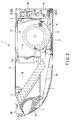
- FIG. 2 is a longitudinal sectional view of the indoor unit.
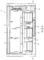
- FIG. 3 is a bottom view illustrating an internal structure of the indoor unit.
- a unit body 1 (an air conditioner body) is configured to be hooked onto a hanging bolt hung from a beam, etc., under a roof (not shown) exposed to an interior of a room and attached extremely adjacently to a ceiling plane.
- the unit body 1 is formed such that the width (a horizontal direction) is much greater than the thickness (a vertical direction).
- the unit body 1 comprises a bottom plate portion 1a forming a lower surface, a top plate portion 1b forming an upper surface adjacent to a ceiling in a state where the unit body 1 is hung down, a pair of right and left side plate portions 1c for connecting the bottom plate portion 1a and the top plate portion 1b, and a back surface portion 1d.
- the bottom plate portion 1a has a suction port 2 to which a grille 10 and a filter 11 are detachably fitted along the width direction of the bottom plate portion 1a.
- the suction port 2 has a substantially half size of the bottom plate portion 1a in the back and forth direction orthogonal to the width direction of the bottom plate portion 1a.
- a discharge port 3 to which a horizontal louver 12 is openably and closably attached is provided at a front surface of the unit body 1.
- a partition plate 6 is provided inside the unit body 1.
- the partition plate 6 stands along a side edge of the suction port 2 to which the above-described grille 10 is fitted, and is extended to be in contact with the top plate portion 1b of the unit body 1. Also, the partition plate 6 is extended to be in contact with right and left side plate portions 1c, and partitions the unit body 1 into two chambers A and B.
- an air supply chamber A located on a side of the suction port 2 and a heat exchange chamber B located on a side of the discharge port 3 are formed inside the unit body 1 with the partition plate 6 placed between the air supply chamber A and the heat exchange chamber B.
- An air supply device S and an electric component box 9 containing electric components for driving and controlling the air supply device S etc. are arranged in the air supply chamber A, as described later.
- An indoor heat exchanger 5 is arranged in the heat exchange chamber B.
- the air supply device S arranged in the air supply chamber A comprises a two-shaft fan motor 15 whose rotary shafts are projected from both sides, one or two fans fitted to each of right and left rotary shafts of the fan motor 15, and fan casings 17 each containing the fan.
- the fan casing 17 comprises a suction opening around the rotary shafts.
- a discharge port body 17a, passing through the partition plate 6 and projecting toward the heat exchange chamber B is integrally provided with the fan casing 17.
- the electrical component box 9 arranged in the air supply chamber A is inserted into a small space (gap) formed between the fan casing 17 and the back surface portion 1d which is a wall surface of the unit body 1, and attached, as described later.
- the indoor heat exchanger 5 and a drain receiver 7 are contained in the heat exchange chamber B.
- the drain receiver 7 is located below the indoor heat exchanger 5. Since the unit body 1 is formed to be shortened in the vertical direction as much as possible, the indoor heat exchanger 5 is obliquely arranged to be extremely inclined.
- the drain receiver 7 is formed of, for example, thick synthetic resin material.
- the drain receiver 7 is formed in a large area covering almost the entire base of the heat exchange chamber B in order to receive all drain water drops generated by a refrigeration cycle operation and dripped from the inclined indoor heat exchanger 5.
- the drain receiver 7 is connected to a drain hose, and communicates with a drain pump device D arranged at a corner of the air supply chamber A.
- the drain pump device D pumps up drain water gathering in the drain receiver 7, and pumps it out in a predetermined area.
- An upper heat insulator 30 supporting an upper end of the indoor heat exchanger 5 is provided in an upper portion of the heat exchange chamber B.
- the upper heat insulator 30 is formed thick, as well as the drain receiver 7, to prevent heat generation (warm heat and cold heat) caused by a refrigeration cycle operation of the indoor heat exchanger 5 from being transferred to a plate material of the unit body 1.
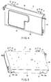
- FIG. 4 is a perspective view of a front surface of the electrical component box 9.
- FIG. 5 is a perspective view of a rear surface of the electrical component box 9.
- the electrical component box 9 comprises a box body 9A and a lid plate 9B, each of which is formed by sheet metal working.
- the one whole surface of the box body 9A is opened.
- a circuit board and electrical components (not shown) are attached inside the box body 9A from this opening.
- part of a fixing tool for attaching the circuit board projects toward a back surface of the box body 9A.
- a swollen portion 20 for keeping rigidity is provided on the lid plate 9B.
- the lid plate 9B is fitted to the opening of the box body 9A and covers the inside of the box body 9A.
- a pair of right and left attaching tongue portions 21 and 22 are provided in an upper end of the box body 9A and the lid plate 9B in the figure.
- the attaching tongue portion 22 of the lid plate 9B is screwed and fixed to the attaching tongue portion 21 of the box body 9A by an attaching screw 23.
- An attaching screw 24 for fixing the attaching tongue portion 21 to an attaching portion provided in the unit body 1 and described later is attached to the attaching tongue portion 21 of the box body 9A.
- a pair of right and left holes 25 are provided in a lower end of the electrical component box 9 in the figure.
- Each hole 25 comprises a rectangular hole 25a which is rectangular and a fitting notch 25b.
- the fitting notch 25b extends only one side of the rectangular hole 25a which is along a longitudinal direction of the electrical component box 9.
- the fitting notch 25b extends the side in the longitudinal direction of the electrical component box 9a.
- the figure is turned upside down to contain and arrange the electrical component box 9 in the air supply chamber A of the unit body 1. That is, an end in which the hole 25 is provided is on the side of a top plate portion 9b, and an end in which the attaching tongue portions 21 and 22 are provided is on the side of a bottom plate portion 9a.
- the lid plate 9B on which the swollen portion 20 shown in FIG. 4 is provided is directed toward the air supply device S.
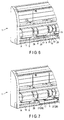
- FIG. 6 is a perspective view illustrating part of the internal structure of the unit body 1 before the electrical component box 9 is attached.
- the direction of the unit body 1 is made different from the actual direction to easily illustrate the structure.
- a lower end of the unit body 1 in FIG. 6 indicates the back surface portion 1d.
- a drawn portion 28 formed to be swollen inside the unit body 1 is provided in part of the back surface portion 1d.
- the drawn portion 28 comprises a long relief hole a.
- the bottom plate portion 1a forming a lower surface is attached to a front opening of the unit body 1 in FIG. 6 later.
- a pair of right and left attaching portions 29, each of which comprises a screw hole, are provided in an area in which the bottom plate portion 1a intersects the back surface portion 1d.
- the pair of attaching portions 29 are located apart from each other at a predetermined interval.
- a back surface of the unit body 1 in FIG. 6 is the top plate portion 1b, and a pair of right and left projections 31 (only one of them shown) are provided in an intermediate portion between the fan casing 17 which is a component of the air supply device S and the back surface portion 1d.
- the pair of projections 31 are provided apart from each other at a predetermined interval.
- Each projection 31 is formed as described later, and located nearly in face of an extension of the attaching portion 29.
- FIG. 7 is a perspective view illustrating the internal structure of the unit body 1 in which the electrical component box 9 is attached. Likewise, the direction of the unit body 1 is consistent with that in FIG. 6 to easily illustrate the structure.
- the electrical component box 9 is on the back surface portion 1d of the unit body 1. Specifically, the electrical component box 9 is on the drawn portion 28 provided in the back surface portion 1d. The fixing tool projecting from the box body 9A of the electrical component box 9 is inserted into the long relief hole a provided in the drawn portion 28.
- the attaching tongue portion 21 provided in the box body 9A of the electrical component box 9 is overlaid on the attaching portion 29 provided in the unit body 1, and attached by an attaching screw after positioning.
- the hole 25 provided in the electrical component box 9 is fitted to the projection (not shown) of the unit body 1 and attached as described later.
- the electrical component box 9 is attached to small space between the air supply device S and the back surface portion 1d of the unit body 1 in the air supply chamber A.
- the hole 25 is engaged with the projection 31 of the top plate portion 1b of the unit body 1, and the electrical component box 9 is screwed and fixed to an end of the back surface portion 1d.
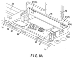
- FIG. 8A illustrates a first process for attaching the electrical component box 9 to the unit body 1.
- the lid plate 9B is detached and only the box body 9A is shown for ease of understanding.
- a lower plate surface in the figure is the back surface portion 1d of the unit body 1.
- the electrical component box 9 is on the drawn portion 28 provided in the back surface portion 1d.
- the attaching portion 29 is formed to be swollen in the end of the back surface portion 1d for attaching a grille 10.
- the attaching portion 29 is displaced from the attaching tongue portion 21 provided in the electrical component box 9.
- a back plate surface of the unit body 1 in the figure is the top plate portion 1b.
- the projection 31 provided in the top plate portion 1b is inserted into and loosely fitted to the hole 25 provided in the electrical component box 9. Thus, the projection 31 can be extremely easily fitted to the hole 25.
- FIGS. 8B and 8C are an enlarged perspective view and an enlarged elevation view illustrating a relationship between the projection 31 provided in the unit body 1 by a cut-and-raised process and the hole 25 provided in the electrical component box 9.
- the projection 31 is cut and raised to be rectangular.
- the continuous two sides formed by an upper side 31a and a left side 31b of the projection 31 especially indicated by hatching in FIG. 8C are connecting sides connecting the unit body 1.
- the continuous two sides formed by a lower side 31c and a right side 31d of the projection 31 not indicated by hatching are separated sides separated from the unit body 1.
- the cut-and-raised height of the projection 31 cut and raised from the unit body 1 needs to be at least greater to some extent than the thickness of the plate of the box body 9A which is a component of the electrical component box 9.
- the hole 25 comprises the rectangular hole 25a and the fitting notch 25b.
- the rectangular hole 25a is formed to be greater to some extent than the rectangular projection 31 in vertical and horizontal directions.
- the fitting notch 25b is cut especially from an upper portion of the rectangular hole 25a in a horizontal direction in the figure.
- the fitting notch 25b is formed along an extension of the upper side 31a of the projection 31, the upper side 31a being connected to the unit body 1.
- the length L of the fitting notch 25b is substantially identical to that of the upper side 31a of the projection 31, or smaller than that of the upper side 31a.
- the vertical width h of the fitting notch 25b is slightly greater than the thickness of the plate of the unit body 1.
- a back surface portion 9d which is the box body 9A of the electrical component box 9 is put on the drawn portion 28 provided in the back surface portion 1d of the unit body 1, and the rectangular holes 25a forming part of the holes 25 of the electrical component box 9 is loosely fitted to the projections 31 of the unit body 1, then the electrical component box 9 is slid and urged to the left in the figure.
- the upper side 31a which is the connecting side of the projection 31 enters the fitting notch 25b which is cut in the horizontal direction at the upper portion of the rectangular hole 25a.
- the rectangular hole 25a forming part of the hole 25 is displaced from a cut-and-raised hole after the projection 31 is cut and raised.
- FIG. 9A is a perspective view illustrating a state where the electrical component box 9 is slid and urged to a predetermined position of the unit body 1.
- FIG. 9B is a perspective view illustrating a state of the hole 25 and the projection 31 at that time.
- FIG. 9C is an elevation view of the hole 25 and the projection 31.
- the cut-and-raised height of the projection 31 is set to be greater than the thickness of the plate of the box body 9A which is the component of the electrical component box 9.
- the upper side 31a forming part of the projection 31 of the unit body 1 is fitted to the fitting notch 25b forming part of the hole 25 of the electrical component box 9, and the rectangular hole 25a gradually faces the projection 31 and the cut-and-raised hole.
- a distal portion of the fitting notch 25b is hooked onto that of the upper side 31a of the projection 31, and further sliding and urging are restricted.
- the upper side 31a is fitted to almost entire part of the fitting notch 25b based on the setting of the lengths of the fitting notch 25b and the upper side 31a.
- the electrical component box 9 is kept parallel at any position without being inclined, and a correct posture is kept.
- the electrical component box 9 is contained and arranged in small space between the fan casing 17 forming part of the air supply device S in the air supply chamber A and the back surface portion 1d of the unit body 1.
- the back surface portion 9d of the electrical component box 9 closely contacts the drawn portion 28 of the back surface portion 1d of the unit body 1, and the upper side 31a of the projection 31 is fitted to the fitting notch 25b forming part of the hole 25.
- positioning of the electrical component box 9 with respect to the unit body 1 and the air supply device S can be easily made merely by inserting the projection 31 of the unit body 1 into the hole 25 of the electrical component box 9, and sliding the electrical component box 9 in a predetermined direction.
- the attachment is made using minimum number of attaching screws 24 (two attaching screws 24), and improvement of workability and reduction of working hours can be achieved.
- the projection 31 is cut and raised to be rectangular. Two continuous sides 31c and 31d are separated sides separated from the unit body 1, and the other two continuous sides 31a and 31b are the connecting sides connecting the unit body 1. Thus, the rigidity of the projection 31 can be increased, and the projection 31 can fully bear an impact load, for example, during transportation.
- the projection 31 and the hole 25 are provided in the top plate portions 1b and 9b of each of the unit body 1 and the electrical component box 9.
- the drawn portion 28 is provided in the back surface portion 1d of the unit body 1.
- the attaching portion 29 and the attaching tongue portion 21 are provided in the bottom plate portions 1a and 9a of each of the unit body 1 and the electrical component box 9.
- the embodiment is not limited to this case. Conversely, even if the hole 25 is provided in the unit body 1 and the projection 31 is provided in the electrical component box 9, the above structure can be achieved.
- a ceiling suspended air conditioner has been described as an embodiment, the embodiment is not limited to this type. Obviously, it can be applied to a ceiling-mounted air conditioner which is arranged on a back side of a ceiling board and whose duct is connected to a suction port and a discharge port.
Landscapes
- Engineering & Computer Science (AREA)
- Chemical & Material Sciences (AREA)
- Combustion & Propulsion (AREA)
- Mechanical Engineering (AREA)
- General Engineering & Computer Science (AREA)
- Air Filters, Heat-Exchange Apparatuses, And Housings Of Air-Conditioning Units (AREA)
Abstract
Description
- Embodiments described herein relate generally to an air conditioner comprising, for example, a ceiling suspended indoor unit.
- A ceiling suspended indoor unit is often used in an air conditioner comprising an indoor unit and an outdoor unit. The ceiling suspended indoor unit does not project from a wall of a room, unlike a so-called wall hung indoor unit, but is hung from a beam, etc., under a roof. Since it is attached almost in close contact with a ceiling board, the unit is unobtrusive in a room.
- This kind of indoor unit is equipped with a partition plate partitioning a heat exchange chamber for arranging a heat exchanger and an air supply chamber for arranging an air supply device in a unit body (housing). An electrical component box is arranged in the air supply chamber. This electrical component box contains electrical components for receiving an instruction signal from a remote control unit and driving and controlling the air supply device, a louver, etc.
- Patent Literature 1:
JP 2012-93044 A - Usually, the electrical component box is arranged in extremely small space between the air supply device in the air supply chamber and a back surface plate of the unit body. To attach the electrical component box, for example, a plurality of holes provided in the electrical component box are hooked onto a plurality of projections provided in a top plate portion of the unit body, and other portions are screwed and fixed to each other. The holes are merely linear slit notches. The projections are rectangular and three sides thereof are cut and raised.
- Since the projections are connected to the top plate portion on only one side, the strength of the projections causes anxiety. The plurality of holes are opened at a plate surface of the electrical component box with a large area. However, a plurality of projections have to be simultaneously engaged, which is troublesome. Also, since the position of the electrical component box is not regulated, the electrical component box is easy to move in small space and hard to screw and fix, even if the projections are engaged with the holes.
- Under such circumstances, an air conditioner in which the strength of an engaging portion of the electrical component box is increased and the rigidity against vibration during transportation is improved and which can be easily attached is desired.
- According to one embodiment, an air conditioner comprises an air conditioner body comprises an electrical component box containing an electrical component; a drawn portion formed in the air conditioner body to be swollen and configured to closely contact the electrical component box; a projection provided in one of the air conditioner body and the electrical component box by a cut-and-raised process, and a hole which is provided in the other one of the air conditioner body and the electrical component box, to which the projection is fitted and which is slid along the drawn portion of the air conditioner body and hooked onto the projection; and an attaching portion for screwing and fixing the electrical component box to the air conditioner body at a position at which the projection is hooked onto the hole.
-
-
FIG. 1 is an appearance perspective view of an indoor unit of an air conditioner according to one embodiment. -
FIG. 2 is a longitudinal sectional view of the indoor unit according to the embodiment. -
FIG. 3 is a bottom view illustrating an internal structure of the indoor unit according to the embodiment. -
FIG. 4 is a perspective view of a front surface of an electrical component box according to the embodiment. -
FIG. 5 is a perspective view of a rear surface of the electrical component box according to the embodiment. -
FIG. 6 is a perspective view illustrating part of the internal structure of the indoor unit before the electrical component box according to the embodiment is attached. -
FIG. 7 is a perspective view illustrating part of the internal structure of the indoor unit in which the electrical component box is attached according to the embodiment. -
FIG. 8A is a perspective view illustrating a state in the middle of attaching the electrical component box according to the embodiment. -
FIG. 8B is a perspective view illustrating a relationship between a projection and a hole in the middle of attaching the electrical component box according to the embodiment. -
FIG. 8C is an elevation view illustrating the relationship between the projection and the hole in the middle of attaching the electrical component box according to the embodiment. -
FIG. 9A is a perspective view illustrating a state where the electrical component box is attached according to the embodiment. -
FIG. 9B is a perspective view illustrating the relationship between the projection and the hole in the state where the electrical component box according to the embodiment is attached. -
FIG. 9C is an elevation view illustrating the relationship between the projection and the hole in the state where the electrical component box is attached according to the embodiment. - An air conditioner according to one embodiment will be hereinafter described with reference to the drawings.
-
FIG. 1 is an appearance perspective view of an indoor unit of the air conditioner.FIG. 2 is a longitudinal sectional view of the indoor unit.FIG. 3 is a bottom view illustrating an internal structure of the indoor unit. - In the figures, a unit body 1 (an air conditioner body) is configured to be hooked onto a hanging bolt hung from a beam, etc., under a roof (not shown) exposed to an interior of a room and attached extremely adjacently to a ceiling plane. The
unit body 1 is formed such that the width (a horizontal direction) is much greater than the thickness (a vertical direction). - The
unit body 1 comprises abottom plate portion 1a forming a lower surface, atop plate portion 1b forming an upper surface adjacent to a ceiling in a state where theunit body 1 is hung down, a pair of right and leftside plate portions 1c for connecting thebottom plate portion 1a and thetop plate portion 1b, and aback surface portion 1d. - The
bottom plate portion 1a has asuction port 2 to which agrille 10 and afilter 11 are detachably fitted along the width direction of thebottom plate portion 1a. Thesuction port 2 has a substantially half size of thebottom plate portion 1a in the back and forth direction orthogonal to the width direction of thebottom plate portion 1a. Adischarge port 3 to which ahorizontal louver 12 is openably and closably attached is provided at a front surface of theunit body 1. - A
partition plate 6 is provided inside theunit body 1. Thepartition plate 6 stands along a side edge of thesuction port 2 to which the above-describedgrille 10 is fitted, and is extended to be in contact with thetop plate portion 1b of theunit body 1. Also, thepartition plate 6 is extended to be in contact with right and leftside plate portions 1c, and partitions theunit body 1 into two chambers A and B. - That is, an air supply chamber A located on a side of the
suction port 2 and a heat exchange chamber B located on a side of thedischarge port 3 are formed inside theunit body 1 with thepartition plate 6 placed between the air supply chamber A and the heat exchange chamber B. An air supply device S and anelectric component box 9 containing electric components for driving and controlling the air supply device S etc. are arranged in the air supply chamber A, as described later. Anindoor heat exchanger 5 is arranged in the heat exchange chamber B. - The air supply device S arranged in the air supply chamber A comprises a two-
shaft fan motor 15 whose rotary shafts are projected from both sides, one or two fans fitted to each of right and left rotary shafts of thefan motor 15, andfan casings 17 each containing the fan. - When the
fan motor 15 rotates and drives the fans, the fans draw air from an axial direction and discharge it from a circumferential direction. Thefan casing 17 comprises a suction opening around the rotary shafts. - A
discharge port body 17a, passing through thepartition plate 6 and projecting toward the heat exchange chamber B is integrally provided with thefan casing 17. - On the other hand, the
electrical component box 9 arranged in the air supply chamber A is inserted into a small space (gap) formed between thefan casing 17 and theback surface portion 1d which is a wall surface of theunit body 1, and attached, as described later. - The
indoor heat exchanger 5 and a drain receiver 7 are contained in the heat exchange chamber B. The drain receiver 7 is located below theindoor heat exchanger 5. Since theunit body 1 is formed to be shortened in the vertical direction as much as possible, theindoor heat exchanger 5 is obliquely arranged to be extremely inclined. - The drain receiver 7 is formed of, for example, thick synthetic resin material. The drain receiver 7 is formed in a large area covering almost the entire base of the heat exchange chamber B in order to receive all drain water drops generated by a refrigeration cycle operation and dripped from the inclined
indoor heat exchanger 5. - The drain receiver 7 is connected to a drain hose, and communicates with a drain pump device D arranged at a corner of the air supply chamber A. The drain pump device D pumps up drain water gathering in the drain receiver 7, and pumps it out in a predetermined area.
- An
upper heat insulator 30 supporting an upper end of theindoor heat exchanger 5 is provided in an upper portion of the heat exchange chamber B. Theupper heat insulator 30 is formed thick, as well as the drain receiver 7, to prevent heat generation (warm heat and cold heat) caused by a refrigeration cycle operation of theindoor heat exchanger 5 from being transferred to a plate material of theunit body 1. - Next, the
electrical component box 9 arranged in the air supply chamber A will be described. -
FIG. 4 is a perspective view of a front surface of theelectrical component box 9.FIG. 5 is a perspective view of a rear surface of theelectrical component box 9. - The
electrical component box 9 comprises abox body 9A and alid plate 9B, each of which is formed by sheet metal working. The one whole surface of thebox body 9A is opened. A circuit board and electrical components (not shown) are attached inside thebox body 9A from this opening. Also, part of a fixing tool for attaching the circuit board projects toward a back surface of thebox body 9A. Aswollen portion 20 for keeping rigidity is provided on thelid plate 9B. Thelid plate 9B is fitted to the opening of thebox body 9A and covers the inside of thebox body 9A. - A pair of right and left attaching
tongue portions box body 9A and thelid plate 9B in the figure. The attachingtongue portion 22 of thelid plate 9B is screwed and fixed to the attachingtongue portion 21 of thebox body 9A by an attachingscrew 23. An attachingscrew 24 for fixing the attachingtongue portion 21 to an attaching portion provided in theunit body 1 and described later is attached to the attachingtongue portion 21 of thebox body 9A. - As shown in only
FIG. 5 , a pair of right and leftholes 25 are provided in a lower end of theelectrical component box 9 in the figure. Eachhole 25 comprises arectangular hole 25a which is rectangular and afitting notch 25b. Thefitting notch 25b extends only one side of therectangular hole 25a which is along a longitudinal direction of theelectrical component box 9. Thefitting notch 25b extends the side in the longitudinal direction of theelectrical component box 9a. - In reality, the figure is turned upside down to contain and arrange the
electrical component box 9 in the air supply chamber A of theunit body 1. That is, an end in which thehole 25 is provided is on the side of atop plate portion 9b, and an end in which the attachingtongue portions bottom plate portion 9a. Thelid plate 9B on which theswollen portion 20 shown inFIG. 4 is provided is directed toward the air supply device S. -
FIG. 6 is a perspective view illustrating part of the internal structure of theunit body 1 before theelectrical component box 9 is attached. The direction of theunit body 1 is made different from the actual direction to easily illustrate the structure. - A lower end of the
unit body 1 inFIG. 6 indicates theback surface portion 1d. A drawnportion 28 formed to be swollen inside theunit body 1 is provided in part of theback surface portion 1d. The drawnportion 28 comprises a long relief hole a. Thebottom plate portion 1a forming a lower surface is attached to a front opening of theunit body 1 inFIG. 6 later. A pair of right and left attachingportions 29, each of which comprises a screw hole, are provided in an area in which thebottom plate portion 1a intersects theback surface portion 1d. The pair of attachingportions 29 are located apart from each other at a predetermined interval. - In addition, a back surface of the
unit body 1 inFIG. 6 is thetop plate portion 1b, and a pair of right and left projections 31 (only one of them shown) are provided in an intermediate portion between thefan casing 17 which is a component of the air supply device S and theback surface portion 1d. The pair ofprojections 31 are provided apart from each other at a predetermined interval. Eachprojection 31 is formed as described later, and located nearly in face of an extension of the attachingportion 29. -
FIG. 7 is a perspective view illustrating the internal structure of theunit body 1 in which theelectrical component box 9 is attached. Likewise, the direction of theunit body 1 is consistent with that inFIG. 6 to easily illustrate the structure. - In the figure, the
electrical component box 9 is on theback surface portion 1d of theunit body 1. Specifically, theelectrical component box 9 is on the drawnportion 28 provided in theback surface portion 1d. The fixing tool projecting from thebox body 9A of theelectrical component box 9 is inserted into the long relief hole a provided in the drawnportion 28. - The attaching
tongue portion 21 provided in thebox body 9A of theelectrical component box 9 is overlaid on the attachingportion 29 provided in theunit body 1, and attached by an attaching screw after positioning. Thehole 25 provided in theelectrical component box 9 is fitted to the projection (not shown) of theunit body 1 and attached as described later. - As shown above, the
electrical component box 9 is attached to small space between the air supply device S and theback surface portion 1d of theunit body 1 in the air supply chamber A. To be specific, thehole 25 is engaged with theprojection 31 of thetop plate portion 1b of theunit body 1, and theelectrical component box 9 is screwed and fixed to an end of theback surface portion 1d. -
FIG. 8A illustrates a first process for attaching theelectrical component box 9 to theunit body 1. InFIG. 8A , thelid plate 9B is detached and only thebox body 9A is shown for ease of understanding. A lower plate surface in the figure is theback surface portion 1d of theunit body 1. Theelectrical component box 9 is on the drawnportion 28 provided in theback surface portion 1d. - The attaching
portion 29 is formed to be swollen in the end of theback surface portion 1d for attaching agrille 10. The attachingportion 29 is displaced from the attachingtongue portion 21 provided in theelectrical component box 9. - A back plate surface of the
unit body 1 in the figure is thetop plate portion 1b. Theprojection 31 provided in thetop plate portion 1b is inserted into and loosely fitted to thehole 25 provided in theelectrical component box 9. Thus, theprojection 31 can be extremely easily fitted to thehole 25. -
FIGS. 8B and 8C are an enlarged perspective view and an enlarged elevation view illustrating a relationship between theprojection 31 provided in theunit body 1 by a cut-and-raised process and thehole 25 provided in theelectrical component box 9. - The
projection 31 is cut and raised to be rectangular. The continuous two sides formed by anupper side 31a and aleft side 31b of theprojection 31 especially indicated by hatching inFIG. 8C are connecting sides connecting theunit body 1. On the other hand, the continuous two sides formed by alower side 31c and aright side 31d of theprojection 31 not indicated by hatching are separated sides separated from theunit body 1. - The cut-and-raised height of the
projection 31 cut and raised from theunit body 1 needs to be at least greater to some extent than the thickness of the plate of thebox body 9A which is a component of theelectrical component box 9. - On the other hand, the
hole 25 comprises therectangular hole 25a and thefitting notch 25b. Therectangular hole 25a is formed to be greater to some extent than therectangular projection 31 in vertical and horizontal directions. Thefitting notch 25b is cut especially from an upper portion of therectangular hole 25a in a horizontal direction in the figure. - It should be noted that the
fitting notch 25b is formed along an extension of theupper side 31a of theprojection 31, theupper side 31a being connected to theunit body 1. The length L of thefitting notch 25b is substantially identical to that of theupper side 31a of theprojection 31, or smaller than that of theupper side 31a. The vertical width h of thefitting notch 25b is slightly greater than the thickness of the plate of theunit body 1. - As described above, a
back surface portion 9d which is thebox body 9A of theelectrical component box 9 is put on the drawnportion 28 provided in theback surface portion 1d of theunit body 1, and therectangular holes 25a forming part of theholes 25 of theelectrical component box 9 is loosely fitted to theprojections 31 of theunit body 1, then theelectrical component box 9 is slid and urged to the left in the figure. - In this state, the
upper side 31a which is the connecting side of theprojection 31 enters thefitting notch 25b which is cut in the horizontal direction at the upper portion of therectangular hole 25a. Therectangular hole 25a forming part of thehole 25 is displaced from a cut-and-raised hole after theprojection 31 is cut and raised. -
FIG. 9A is a perspective view illustrating a state where theelectrical component box 9 is slid and urged to a predetermined position of theunit body 1.FIG. 9B is a perspective view illustrating a state of thehole 25 and theprojection 31 at that time.FIG. 9C is an elevation view of thehole 25 and theprojection 31. - As stated above, the cut-and-raised height of the
projection 31 is set to be greater than the thickness of the plate of thebox body 9A which is the component of theelectrical component box 9. Thus, when theelectrical component box 9 is slid and urged in a predetermined direction, theupper side 31a forming part of theprojection 31 of theunit body 1 is fitted to thefitting notch 25b forming part of thehole 25 of theelectrical component box 9, and therectangular hole 25a gradually faces theprojection 31 and the cut-and-raised hole. - Finally, a distal portion of the
fitting notch 25b is hooked onto that of theupper side 31a of theprojection 31, and further sliding and urging are restricted. Theupper side 31a is fitted to almost entire part of thefitting notch 25b based on the setting of the lengths of thefitting notch 25b and theupper side 31a. Furthermore, since the pair of right and leftprojections 31 and the pair of right and leftholes 25 are provided, theelectrical component box 9 is kept parallel at any position without being inclined, and a correct posture is kept. - An attaching hole provided in the attaching
tongue portion 21 of theelectrical component box 9 at this moment correctly faces the screw hole provided in the attachingportion 29 formed to be swollen in theunit body 1. Then, the attachingscrew 24 is screwed to the screw hole through the attaching hole. On the other hand, theback surface portion 9d of theelectrical component box 9 is in contact with the drawnportion 28 provided in theback surface portion 1d of theunit body 1 and slid on the drawnportion 28. - Eventually, as shown in
FIGS. 1 ,3 and5 , theelectrical component box 9 is contained and arranged in small space between thefan casing 17 forming part of the air supply device S in the air supply chamber A and theback surface portion 1d of theunit body 1. Theback surface portion 9d of theelectrical component box 9 closely contacts the drawnportion 28 of theback surface portion 1d of theunit body 1, and theupper side 31a of theprojection 31 is fitted to thefitting notch 25b forming part of thehole 25. - Consequently, even if an interval between the
back surface portion 1d of theunit body 1 and thefan casing 17 of the air supply device S is extremely short, a position of theelectrical component box 9 can be surely regulated and theelectrical component box 9 can be arranged without contacting thefan casing 17. Since the attachingscrew 24 is screwed to the attaching hole provided in the attachingtongue portion 21 of theelectrical component box 9 and the screw hole provided in the attachingportion 29 of theunit body 1, theelectrical component box 9 can be surely attached. - In particular, positioning of the
electrical component box 9 with respect to theunit body 1 and the air supply device S can be easily made merely by inserting theprojection 31 of theunit body 1 into thehole 25 of theelectrical component box 9, and sliding theelectrical component box 9 in a predetermined direction. The attachment is made using minimum number of attaching screws 24 (two attaching screws 24), and improvement of workability and reduction of working hours can be achieved. - Even if the attaching
screws 24 are detached at the time of maintenance, theelectrical component box 9 remains hooked onto theunit body 1 and is not dropped. As a result, safety can be secured. - The
projection 31 is cut and raised to be rectangular. Twocontinuous sides unit body 1, and the other twocontinuous sides unit body 1. Thus, the rigidity of theprojection 31 can be increased, and theprojection 31 can fully bear an impact load, for example, during transportation. - The
projection 31 and thehole 25 are provided in thetop plate portions unit body 1 and theelectrical component box 9. The drawnportion 28 is provided in theback surface portion 1d of theunit body 1. The attachingportion 29 and the attachingtongue portion 21 are provided in thebottom plate portions unit body 1 and theelectrical component box 9. Thus, theelectrical component box 9 can be easily positioned, and the rigidity of theunit body 1 can be improved. - It should be noted that although the
projection 31 is provided in theunit body 1 and thehole 25 is provided in theelectrical component box 9, the embodiment is not limited to this case. Conversely, even if thehole 25 is provided in theunit body 1 and theprojection 31 is provided in theelectrical component box 9, the above structure can be achieved. - Moreover, although a ceiling suspended air conditioner has been described as an embodiment, the embodiment is not limited to this type. Obviously, it can be applied to a ceiling-mounted air conditioner which is arranged on a back side of a ceiling board and whose duct is connected to a suction port and a discharge port.
- While certain embodiments have been described, these embodiments have been presented by way of example only, and are not intended to limit the scope of the inventions. Indeed, the novel embodiments described herein may be embodied in a variety of other forms; furthermore, various omissions, substitutions and changes in the form of the embodiments described herein may be made without departing from the spirit of the inventions. The accompanying claims and their equivalents are intended to cover such forms or modifications as would fall within the scope and spirit of the inventions.
Claims (4)
- An air conditioner comprising:an air conditioner body comprising an electrical component box containing an electrical component;a drawn portion formed in the air conditioner body to be swollen and configured to closely contact the electrical component box;a projection provided in one of the air conditioner body and the electrical component box by a cut-and-raised process, and a hole which is provided in the other one of the air conditioner body and the electrical component box, to which the projection is fitted and which is slid along the drawn portion of the air conditioner body and hooked onto the projection; andan attaching portion for screwing and fixing the electrical component box to the air conditioner body at a position at which the projection is hooked onto the hole.
- The air conditioner of Claim 1, wherein:the projection is rectangular and comprises connecting sides on which two continuous sides connect to either the air conditioner body or the electrical component box, and separated sides on which the other two continuous sides are separated from either the air conditioner body or the electrical component box; andthe hole comprises a rectangular hole opened to be loosely fitted to the projection, and a fitting notch which is cut from part of the rectangular hole and to which one of the connecting sides of the projection is fitted when the electrical component box is slid.
- The air conditioner of Claim 1, wherein:each of the projection and the hole is provided in a top plate portion of each of the air conditioner body and the electrical component box;the drawn portion is provided in a back surface portion of the air conditioner body; andthe attaching portion is provided in a bottom plate portion of each of the air conditioner body and the electrical component box.
- The air conditioner of Claim 1, wherein each of the projection and the hole is provided in a plurality of positions separated from each other along a sliding direction of the electrical component box.
Applications Claiming Priority (2)
| Application Number | Priority Date | Filing Date | Title |
|---|---|---|---|
| JP2013065520 | 2013-03-27 | ||
| PCT/JP2014/055976 WO2014156563A1 (en) | 2013-03-27 | 2014-03-07 | Air conditioner |
Publications (3)
| Publication Number | Publication Date |
|---|---|
| EP2980502A1 true EP2980502A1 (en) | 2016-02-03 |
| EP2980502A4 EP2980502A4 (en) | 2016-12-21 |
| EP2980502B1 EP2980502B1 (en) | 2020-05-06 |
Family
ID=51623549
Family Applications (1)
| Application Number | Title | Priority Date | Filing Date |
|---|---|---|---|
| EP14773702.7A Active EP2980502B1 (en) | 2013-03-27 | 2014-03-07 | Air conditioner |
Country Status (5)
| Country | Link |
|---|---|
| EP (1) | EP2980502B1 (en) |
| JP (1) | JP6019217B2 (en) |
| CN (1) | CN105102901B (en) |
| AR (1) | AR095766A1 (en) |
| WO (1) | WO2014156563A1 (en) |
Families Citing this family (1)
| Publication number | Priority date | Publication date | Assignee | Title |
|---|---|---|---|---|
| JP2019124405A (en) * | 2018-01-17 | 2019-07-25 | 日立グローバルライフソリューションズ株式会社 | Refrigerator comprising control board placement member, and control board placement member |
Family Cites Families (11)
| Publication number | Priority date | Publication date | Assignee | Title |
|---|---|---|---|---|
| JPS54163042U (en) * | 1978-05-04 | 1979-11-15 | ||
| JPS6144122U (en) * | 1984-08-28 | 1986-03-24 | 株式会社東芝 | air conditioner |
| JPH0650189B2 (en) * | 1988-10-07 | 1994-06-29 | 松下電器産業株式会社 | Power supply box for integrated air conditioner |
| JPH04131628A (en) * | 1990-09-20 | 1992-05-06 | Mitsubishi Electric Corp | Device for fixing electric parts box for recessed type air conditioner |
| JPH08270974A (en) * | 1995-03-30 | 1996-10-18 | Mitsubishi Electric Corp | Air conditioner |
| JP3598731B2 (en) * | 1997-05-20 | 2004-12-08 | 株式会社富士通ゼネラル | Ceiling-type air conditioner |
| JP3615366B2 (en) * | 1997-09-22 | 2005-02-02 | 三洋電機株式会社 | Ceiling suspended air conditioner |
| WO2002103251A2 (en) * | 2001-06-19 | 2002-12-27 | Lg Electronics Inc. | Air conditioner |
| JP2009097741A (en) * | 2007-10-15 | 2009-05-07 | Panasonic Corp | Air conditioner indoor unit |
| JP5542616B2 (en) * | 2010-10-28 | 2014-07-09 | 三洋電機株式会社 | Ceiling suspended air conditioner |
| CN201919263U (en) * | 2011-01-19 | 2011-08-03 | 杭州罗盟智能科技有限公司 | Novel aluminium plate frame electric appliance panel-mounting structure |
-
2014
- 2014-03-07 WO PCT/JP2014/055976 patent/WO2014156563A1/en not_active Ceased
- 2014-03-07 CN CN201480018613.6A patent/CN105102901B/en active Active
- 2014-03-07 JP JP2015508240A patent/JP6019217B2/en active Active
- 2014-03-07 EP EP14773702.7A patent/EP2980502B1/en active Active
- 2014-03-26 AR ARP140101376A patent/AR095766A1/en active IP Right Grant
Also Published As
| Publication number | Publication date |
|---|---|
| JPWO2014156563A1 (en) | 2017-02-16 |
| JP6019217B2 (en) | 2016-11-02 |
| CN105102901B (en) | 2018-01-23 |
| EP2980502B1 (en) | 2020-05-06 |
| AR095766A1 (en) | 2015-11-11 |
| CN105102901A (en) | 2015-11-25 |
| EP2980502A4 (en) | 2016-12-21 |
| WO2014156563A1 (en) | 2014-10-02 |
Similar Documents
| Publication | Publication Date | Title |
|---|---|---|
| RU2652963C1 (en) | Outdoor unit of conditioner | |
| KR101019283B1 (en) | Ceiling flush air conditioner | |
| US8763416B2 (en) | Outdoor unit of air conditioner | |
| EP2206978A1 (en) | Outdoor unit for air conditioner | |
| US9903600B2 (en) | Wind direction adjusting device of air-conditioning apparatus and air-conditioning apparatus | |
| GB2564368A (en) | Air conditioner indoor unit | |
| JP6289663B2 (en) | Air conditioner indoor unit | |
| JP4435823B2 (en) | Opening cover device and air conditioner equipped with the same | |
| JP6847306B2 (en) | Outdoor unit of air conditioner | |
| JP2008190806A (en) | Outdoor unit of air conditioner | |
| EP3441693A1 (en) | Air conditioner | |
| EP2980502B1 (en) | Air conditioner | |
| AU2015391312A1 (en) | Indoor unit of air-conditioning apparatus | |
| US20240318862A1 (en) | Embedded ventilation fan | |
| CN107449060B (en) | Window type air conditioner | |
| JP6079053B2 (en) | Air conditioner outdoor unit | |
| CN100436952C (en) | Indoor unit of air conditioner | |
| JP2013213595A (en) | Built-in air conditioner | |
| EP3026363A1 (en) | Heat exchanger, air conditioner and method of manufacturing heat exchanger | |
| JP2018091510A (en) | Indoor unit of air conditioner | |
| EP3521726A1 (en) | Indoor unit for air conditioning device | |
| KR20060105764A (en) | Ceiling air conditioner | |
| EP2568225B1 (en) | Air Conditioner | |
| JP7112030B2 (en) | outdoor unit of air conditioner | |
| JP2012093044A (en) | Ceiling-suspended air conditioner |
Legal Events
| Date | Code | Title | Description |
|---|---|---|---|
| PUAI | Public reference made under article 153(3) epc to a published international application that has entered the european phase |
Free format text: ORIGINAL CODE: 0009012 |
|
| 17P | Request for examination filed |
Effective date: 20150925 |
|
| AK | Designated contracting states |
Kind code of ref document: A1 Designated state(s): AL AT BE BG CH CY CZ DE DK EE ES FI FR GB GR HR HU IE IS IT LI LT LU LV MC MK MT NL NO PL PT RO RS SE SI SK SM TR |
|
| AX | Request for extension of the european patent |
Extension state: BA ME |
|
| DAX | Request for extension of the european patent (deleted) | ||
| A4 | Supplementary search report drawn up and despatched |
Effective date: 20161118 |
|
| RIC1 | Information provided on ipc code assigned before grant |
Ipc: F24F 13/20 20060101AFI20161114BHEP |
|
| GRAP | Despatch of communication of intention to grant a patent |
Free format text: ORIGINAL CODE: EPIDOSNIGR1 |
|
| STAA | Information on the status of an ep patent application or granted ep patent |
Free format text: STATUS: GRANT OF PATENT IS INTENDED |
|
| INTG | Intention to grant announced |
Effective date: 20191127 |
|
| GRAS | Grant fee paid |
Free format text: ORIGINAL CODE: EPIDOSNIGR3 |
|
| GRAA | (expected) grant |
Free format text: ORIGINAL CODE: 0009210 |
|
| STAA | Information on the status of an ep patent application or granted ep patent |
Free format text: STATUS: THE PATENT HAS BEEN GRANTED |
|
| AK | Designated contracting states |
Kind code of ref document: B1 Designated state(s): AL AT BE BG CH CY CZ DE DK EE ES FI FR GB GR HR HU IE IS IT LI LT LU LV MC MK MT NL NO PL PT RO RS SE SI SK SM TR |
|
| REG | Reference to a national code |
Ref country code: GB Ref legal event code: FG4D |
|
| REG | Reference to a national code |
Ref country code: CH Ref legal event code: EP Ref country code: AT Ref legal event code: REF Ref document number: 1267401 Country of ref document: AT Kind code of ref document: T Effective date: 20200515 |
|
| REG | Reference to a national code |
Ref country code: DE Ref legal event code: R096 Ref document number: 602014065067 Country of ref document: DE |
|
| REG | Reference to a national code |
Ref country code: IE Ref legal event code: FG4D |
|
| REG | Reference to a national code |
Ref country code: LT Ref legal event code: MG4D |
|
| REG | Reference to a national code |
Ref country code: NL Ref legal event code: MP Effective date: 20200506 |
|
| PG25 | Lapsed in a contracting state [announced via postgrant information from national office to epo] |
Ref country code: IS Free format text: LAPSE BECAUSE OF FAILURE TO SUBMIT A TRANSLATION OF THE DESCRIPTION OR TO PAY THE FEE WITHIN THE PRESCRIBED TIME-LIMIT Effective date: 20200906 Ref country code: GR Free format text: LAPSE BECAUSE OF FAILURE TO SUBMIT A TRANSLATION OF THE DESCRIPTION OR TO PAY THE FEE WITHIN THE PRESCRIBED TIME-LIMIT Effective date: 20200807 Ref country code: NO Free format text: LAPSE BECAUSE OF FAILURE TO SUBMIT A TRANSLATION OF THE DESCRIPTION OR TO PAY THE FEE WITHIN THE PRESCRIBED TIME-LIMIT Effective date: 20200806 Ref country code: LT Free format text: LAPSE BECAUSE OF FAILURE TO SUBMIT A TRANSLATION OF THE DESCRIPTION OR TO PAY THE FEE WITHIN THE PRESCRIBED TIME-LIMIT Effective date: 20200506 Ref country code: SE Free format text: LAPSE BECAUSE OF FAILURE TO SUBMIT A TRANSLATION OF THE DESCRIPTION OR TO PAY THE FEE WITHIN THE PRESCRIBED TIME-LIMIT Effective date: 20200506 Ref country code: FI Free format text: LAPSE BECAUSE OF FAILURE TO SUBMIT A TRANSLATION OF THE DESCRIPTION OR TO PAY THE FEE WITHIN THE PRESCRIBED TIME-LIMIT Effective date: 20200506 Ref country code: PT Free format text: LAPSE BECAUSE OF FAILURE TO SUBMIT A TRANSLATION OF THE DESCRIPTION OR TO PAY THE FEE WITHIN THE PRESCRIBED TIME-LIMIT Effective date: 20200907 |
|
| PG25 | Lapsed in a contracting state [announced via postgrant information from national office to epo] |
Ref country code: HR Free format text: LAPSE BECAUSE OF FAILURE TO SUBMIT A TRANSLATION OF THE DESCRIPTION OR TO PAY THE FEE WITHIN THE PRESCRIBED TIME-LIMIT Effective date: 20200506 Ref country code: LV Free format text: LAPSE BECAUSE OF FAILURE TO SUBMIT A TRANSLATION OF THE DESCRIPTION OR TO PAY THE FEE WITHIN THE PRESCRIBED TIME-LIMIT Effective date: 20200506 Ref country code: RS Free format text: LAPSE BECAUSE OF FAILURE TO SUBMIT A TRANSLATION OF THE DESCRIPTION OR TO PAY THE FEE WITHIN THE PRESCRIBED TIME-LIMIT Effective date: 20200506 Ref country code: BG Free format text: LAPSE BECAUSE OF FAILURE TO SUBMIT A TRANSLATION OF THE DESCRIPTION OR TO PAY THE FEE WITHIN THE PRESCRIBED TIME-LIMIT Effective date: 20200806 |
|
| REG | Reference to a national code |
Ref country code: AT Ref legal event code: MK05 Ref document number: 1267401 Country of ref document: AT Kind code of ref document: T Effective date: 20200506 |
|
| PG25 | Lapsed in a contracting state [announced via postgrant information from national office to epo] |
Ref country code: AL Free format text: LAPSE BECAUSE OF FAILURE TO SUBMIT A TRANSLATION OF THE DESCRIPTION OR TO PAY THE FEE WITHIN THE PRESCRIBED TIME-LIMIT Effective date: 20200506 Ref country code: NL Free format text: LAPSE BECAUSE OF FAILURE TO SUBMIT A TRANSLATION OF THE DESCRIPTION OR TO PAY THE FEE WITHIN THE PRESCRIBED TIME-LIMIT Effective date: 20200506 |
|
| PG25 | Lapsed in a contracting state [announced via postgrant information from national office to epo] |
Ref country code: DK Free format text: LAPSE BECAUSE OF FAILURE TO SUBMIT A TRANSLATION OF THE DESCRIPTION OR TO PAY THE FEE WITHIN THE PRESCRIBED TIME-LIMIT Effective date: 20200506 Ref country code: ES Free format text: LAPSE BECAUSE OF FAILURE TO SUBMIT A TRANSLATION OF THE DESCRIPTION OR TO PAY THE FEE WITHIN THE PRESCRIBED TIME-LIMIT Effective date: 20200506 Ref country code: CZ Free format text: LAPSE BECAUSE OF FAILURE TO SUBMIT A TRANSLATION OF THE DESCRIPTION OR TO PAY THE FEE WITHIN THE PRESCRIBED TIME-LIMIT Effective date: 20200506 Ref country code: RO Free format text: LAPSE BECAUSE OF FAILURE TO SUBMIT A TRANSLATION OF THE DESCRIPTION OR TO PAY THE FEE WITHIN THE PRESCRIBED TIME-LIMIT Effective date: 20200506 Ref country code: IT Free format text: LAPSE BECAUSE OF FAILURE TO SUBMIT A TRANSLATION OF THE DESCRIPTION OR TO PAY THE FEE WITHIN THE PRESCRIBED TIME-LIMIT Effective date: 20200506 Ref country code: AT Free format text: LAPSE BECAUSE OF FAILURE TO SUBMIT A TRANSLATION OF THE DESCRIPTION OR TO PAY THE FEE WITHIN THE PRESCRIBED TIME-LIMIT Effective date: 20200506 Ref country code: SM Free format text: LAPSE BECAUSE OF FAILURE TO SUBMIT A TRANSLATION OF THE DESCRIPTION OR TO PAY THE FEE WITHIN THE PRESCRIBED TIME-LIMIT Effective date: 20200506 Ref country code: EE Free format text: LAPSE BECAUSE OF FAILURE TO SUBMIT A TRANSLATION OF THE DESCRIPTION OR TO PAY THE FEE WITHIN THE PRESCRIBED TIME-LIMIT Effective date: 20200506 |
|
| REG | Reference to a national code |
Ref country code: DE Ref legal event code: R097 Ref document number: 602014065067 Country of ref document: DE |
|
| PG25 | Lapsed in a contracting state [announced via postgrant information from national office to epo] |
Ref country code: PL Free format text: LAPSE BECAUSE OF FAILURE TO SUBMIT A TRANSLATION OF THE DESCRIPTION OR TO PAY THE FEE WITHIN THE PRESCRIBED TIME-LIMIT Effective date: 20200506 Ref country code: SK Free format text: LAPSE BECAUSE OF FAILURE TO SUBMIT A TRANSLATION OF THE DESCRIPTION OR TO PAY THE FEE WITHIN THE PRESCRIBED TIME-LIMIT Effective date: 20200506 |
|
| PLBE | No opposition filed within time limit |
Free format text: ORIGINAL CODE: 0009261 |
|
| STAA | Information on the status of an ep patent application or granted ep patent |
Free format text: STATUS: NO OPPOSITION FILED WITHIN TIME LIMIT |
|
| 26N | No opposition filed |
Effective date: 20210209 |
|
| PG25 | Lapsed in a contracting state [announced via postgrant information from national office to epo] |
Ref country code: SI Free format text: LAPSE BECAUSE OF FAILURE TO SUBMIT A TRANSLATION OF THE DESCRIPTION OR TO PAY THE FEE WITHIN THE PRESCRIBED TIME-LIMIT Effective date: 20200506 |
|
| PG25 | Lapsed in a contracting state [announced via postgrant information from national office to epo] |
Ref country code: MC Free format text: LAPSE BECAUSE OF FAILURE TO SUBMIT A TRANSLATION OF THE DESCRIPTION OR TO PAY THE FEE WITHIN THE PRESCRIBED TIME-LIMIT Effective date: 20200506 |
|
| REG | Reference to a national code |
Ref country code: CH Ref legal event code: PL |
|
| REG | Reference to a national code |
Ref country code: BE Ref legal event code: MM Effective date: 20210331 |
|
| PG25 | Lapsed in a contracting state [announced via postgrant information from national office to epo] |
Ref country code: CH Free format text: LAPSE BECAUSE OF NON-PAYMENT OF DUE FEES Effective date: 20210331 Ref country code: LI Free format text: LAPSE BECAUSE OF NON-PAYMENT OF DUE FEES Effective date: 20210331 Ref country code: LU Free format text: LAPSE BECAUSE OF NON-PAYMENT OF DUE FEES Effective date: 20210307 Ref country code: IE Free format text: LAPSE BECAUSE OF NON-PAYMENT OF DUE FEES Effective date: 20210307 |
|
| PG25 | Lapsed in a contracting state [announced via postgrant information from national office to epo] |
Ref country code: BE Free format text: LAPSE BECAUSE OF NON-PAYMENT OF DUE FEES Effective date: 20210331 |
|
| PG25 | Lapsed in a contracting state [announced via postgrant information from national office to epo] |
Ref country code: HU Free format text: LAPSE BECAUSE OF FAILURE TO SUBMIT A TRANSLATION OF THE DESCRIPTION OR TO PAY THE FEE WITHIN THE PRESCRIBED TIME-LIMIT; INVALID AB INITIO Effective date: 20140307 |
|
| PG25 | Lapsed in a contracting state [announced via postgrant information from national office to epo] |
Ref country code: CY Free format text: LAPSE BECAUSE OF FAILURE TO SUBMIT A TRANSLATION OF THE DESCRIPTION OR TO PAY THE FEE WITHIN THE PRESCRIBED TIME-LIMIT Effective date: 20200506 |
|
| PG25 | Lapsed in a contracting state [announced via postgrant information from national office to epo] |
Ref country code: MK Free format text: LAPSE BECAUSE OF FAILURE TO SUBMIT A TRANSLATION OF THE DESCRIPTION OR TO PAY THE FEE WITHIN THE PRESCRIBED TIME-LIMIT Effective date: 20200506 |
|
| PG25 | Lapsed in a contracting state [announced via postgrant information from national office to epo] |
Ref country code: TR Free format text: LAPSE BECAUSE OF FAILURE TO SUBMIT A TRANSLATION OF THE DESCRIPTION OR TO PAY THE FEE WITHIN THE PRESCRIBED TIME-LIMIT Effective date: 20200506 |
|
| PG25 | Lapsed in a contracting state [announced via postgrant information from national office to epo] |
Ref country code: MT Free format text: LAPSE BECAUSE OF FAILURE TO SUBMIT A TRANSLATION OF THE DESCRIPTION OR TO PAY THE FEE WITHIN THE PRESCRIBED TIME-LIMIT Effective date: 20200506 |
|
| PGFP | Annual fee paid to national office [announced via postgrant information from national office to epo] |
Ref country code: GB Payment date: 20260220 Year of fee payment: 13 |
|
| PGFP | Annual fee paid to national office [announced via postgrant information from national office to epo] |
Ref country code: DE Payment date: 20260219 Year of fee payment: 13 |
|
| PGFP | Annual fee paid to national office [announced via postgrant information from national office to epo] |
Ref country code: FR Payment date: 20260219 Year of fee payment: 13 |