EP2980481A1 - Aircraft gas turbine having a seal for sealing a spark plug to the combustor chamber wall of a gas turbine - Google Patents
Aircraft gas turbine having a seal for sealing a spark plug to the combustor chamber wall of a gas turbine Download PDFInfo
- Publication number
- EP2980481A1 EP2980481A1 EP15176991.6A EP15176991A EP2980481A1 EP 2980481 A1 EP2980481 A1 EP 2980481A1 EP 15176991 A EP15176991 A EP 15176991A EP 2980481 A1 EP2980481 A1 EP 2980481A1
- Authority
- EP
- European Patent Office
- Prior art keywords
- spark plug
- combustion chamber
- sealing
- chamber wall
- arrangement according
- Prior art date
- Legal status (The legal status is an assumption and is not a legal conclusion. Google has not performed a legal analysis and makes no representation as to the accuracy of the status listed.)
- Withdrawn
Links
Images


Classifications
-
- F—MECHANICAL ENGINEERING; LIGHTING; HEATING; WEAPONS; BLASTING
- F16—ENGINEERING ELEMENTS AND UNITS; GENERAL MEASURES FOR PRODUCING AND MAINTAINING EFFECTIVE FUNCTIONING OF MACHINES OR INSTALLATIONS; THERMAL INSULATION IN GENERAL
- F16J—PISTONS; CYLINDERS; SEALINGS
- F16J15/00—Sealings
- F16J15/02—Sealings between relatively-stationary surfaces
- F16J15/021—Sealings between relatively-stationary surfaces with elastic packing
- F16J15/022—Sealings between relatively-stationary surfaces with elastic packing characterised by structure or material
-
- F—MECHANICAL ENGINEERING; LIGHTING; HEATING; WEAPONS; BLASTING
- F01—MACHINES OR ENGINES IN GENERAL; ENGINE PLANTS IN GENERAL; STEAM ENGINES
- F01D—NON-POSITIVE DISPLACEMENT MACHINES OR ENGINES, e.g. STEAM TURBINES
- F01D11/00—Preventing or minimising internal leakage of working-fluid, e.g. between stages
- F01D11/003—Preventing or minimising internal leakage of working-fluid, e.g. between stages by packing rings; Mechanical seals
-
- F—MECHANICAL ENGINEERING; LIGHTING; HEATING; WEAPONS; BLASTING
- F02—COMBUSTION ENGINES; HOT-GAS OR COMBUSTION-PRODUCT ENGINE PLANTS
- F02C—GAS-TURBINE PLANTS; AIR INTAKES FOR JET-PROPULSION PLANTS; CONTROLLING FUEL SUPPLY IN AIR-BREATHING JET-PROPULSION PLANTS
- F02C7/00—Features, components parts, details or accessories, not provided for in, or of interest apart form groups F02C1/00 - F02C6/00; Air intakes for jet-propulsion plants
- F02C7/26—Starting; Ignition
- F02C7/264—Ignition
- F02C7/266—Electric
-
- F—MECHANICAL ENGINEERING; LIGHTING; HEATING; WEAPONS; BLASTING
- F23—COMBUSTION APPARATUS; COMBUSTION PROCESSES
- F23Q—IGNITION; EXTINGUISHING-DEVICES
- F23Q3/00—Igniters using electrically-produced sparks
- F23Q3/008—Structurally associated with fluid-fuel burners
-
- F—MECHANICAL ENGINEERING; LIGHTING; HEATING; WEAPONS; BLASTING
- F23—COMBUSTION APPARATUS; COMBUSTION PROCESSES
- F23R—GENERATING COMBUSTION PRODUCTS OF HIGH PRESSURE OR HIGH VELOCITY, e.g. GAS-TURBINE COMBUSTION CHAMBERS
- F23R3/00—Continuous combustion chambers using liquid or gaseous fuel
- F23R3/002—Wall structures
-
- F—MECHANICAL ENGINEERING; LIGHTING; HEATING; WEAPONS; BLASTING
- F23—COMBUSTION APPARATUS; COMBUSTION PROCESSES
- F23R—GENERATING COMBUSTION PRODUCTS OF HIGH PRESSURE OR HIGH VELOCITY, e.g. GAS-TURBINE COMBUSTION CHAMBERS
- F23R3/00—Continuous combustion chambers using liquid or gaseous fuel
- F23R3/42—Continuous combustion chambers using liquid or gaseous fuel characterised by the arrangement or form of the flame tubes or combustion chambers
- F23R3/60—Support structures; Attaching or mounting means
-
- F—MECHANICAL ENGINEERING; LIGHTING; HEATING; WEAPONS; BLASTING
- F05—INDEXING SCHEMES RELATING TO ENGINES OR PUMPS IN VARIOUS SUBCLASSES OF CLASSES F01-F04
- F05D—INDEXING SCHEME FOR ASPECTS RELATING TO NON-POSITIVE-DISPLACEMENT MACHINES OR ENGINES, GAS-TURBINES OR JET-PROPULSION PLANTS
- F05D2240/00—Components
- F05D2240/55—Seals
-
- F—MECHANICAL ENGINEERING; LIGHTING; HEATING; WEAPONS; BLASTING
- F23—COMBUSTION APPARATUS; COMBUSTION PROCESSES
- F23R—GENERATING COMBUSTION PRODUCTS OF HIGH PRESSURE OR HIGH VELOCITY, e.g. GAS-TURBINE COMBUSTION CHAMBERS
- F23R2900/00—Special features of, or arrangements for continuous combustion chambers; Combustion processes therefor
- F23R2900/00012—Details of sealing devices
Definitions
- the invention relates to a sealing arrangement according to the preamble of claim 1.
- the invention relates to a sealing arrangement of a spark plug or a measuring probe or a similar component, which is guided through a combustion chamber wall of a gas turbine.
- spark plug is always used, but this is not to be understood as limiting.
- the sealing arrangement according to the invention comprises at least one sealing ring, through which the spark plug or the measuring probe protrudes and which sealingly bears against an edge region of the recess facing away from the combustion chamber interior.
- An embodiment of this kind is for example from the US 2005/0072163 A1 previously known. From the prior art it is known that a spark plug is attached to the combustion chamber housing and protrudes through the single-walled or double-walled combustion chamber wall of the combustion chamber. Due to tolerances and relative movements by pressure and heat flow, a gap must be maintained between the edge region of a recess of the combustion chamber wall and the spark plug in order to avoid direct contact and thus damage to the components. Through this gap, air enters the combustion chamber in an uncontrolled manner and influences the combustion and cooling of the combustion chamber wall.
- the invention has for its object to provide a seal assembly of the type mentioned, which avoids the disadvantages of the prior art with a simple structure and simple, cost-effective manufacturability and leads to an optimized seal.
- the sealing ring is designed in the form of a flat, annular, flexible disc. This is preferably designed as a sheet metal component.
- a significant advantage of the embodiment of the invention is that there is a significantly reduced manufacturing costs. Furthermore, both the cooling air flow and the mixed air flow are only minimally influenced, since the sealing arrangement according to the invention requires a very small installation space.
- the inventively provided sealing ring since it is a flat, lightweight component can be created by the pressure difference between the outside of the combustion chamber wall and the inside of the combustion chamber wall against the combustion chamber wall and kept sealed. It is not necessary to take additional measures to bias or fix the sealing ring against the combustion chamber wall. During operation of the gas turbine thus the sealing ring is located on the outside of the combustion chamber wall and thereby reduces the leakage air flow.
- the sealing ring with radial, relative to its central recess for carrying out the spark plug, slots provided. These slots lead to a considerable increase in the flexibility of the sealing ring, so that it rests sealingly on non-planar areas of the combustion chamber wall.
- a plurality of sealing rings are provided one above the other. These multiple sealing rings can are preferably interconnected, for example via a spot weld. Furthermore, it may be advantageous to arrange the slots of the plurality of sealing rings in the circumferential direction, relative to the sealing ring, offset from each other. This results in a particularly good seal.
- Spark plugs are often located in the lower part of the engine.
- the sealing ring would thus rest against the combustion chamber housing, in particular when the aircraft gas turbine is at a standstill.
- the spark plug is provided with at least one bearing element supporting the sealing ring.
- the contact element can be designed as a retaining ring or as an adapter. In both cases, the contact element can be provided directly on the spark plug. It is also possible to form the abutment element directly in the manufacture of the adapter or the spark plug or to provide abutment elements or spacers on the spark plug, for example by welding.
- the sealing ring is secured by a tubular, elongated adapter. This is positioned outside the sealing ring.
- the spark plug can be carried out through the extended adapter. There are thus no changes to the spark plug itself required.
- the additional, tubular adapter is supported on its, relative to the engine central axis, radially outer region against the adapter, with which the spark plug itself is attached to the combustion chamber housing. It is thus ensured in a reliable manner that the sealing ring or the plurality of sealing rings are accurately positioned.
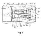
- the gas turbine engine 10 is a generalized example of a turbomachine, in which the invention can be applied.
- the engine 10 is formed in a conventional manner and comprises in the flow direction in succession an air inlet 11, a circulating in a housing fan 12, a medium pressure compressor 13, a high pressure compressor 14, a combustion chamber 15, a high pressure turbine 16, a medium pressure turbine 17 and a low pressure turbine 18 and a Exhaust nozzle 19, which are all arranged around a central engine center axis 1.
- the intermediate-pressure compressor 13 and the high-pressure compressor 14 each comprise a plurality of stages, each of which has a circumferentially extending array of fixed stationary vanes 20, commonly referred to as stator vanes, extending radially inward from the engine casing 21 in an annular flow passage through the compressors 13, 14 protrude.
- the compressors further include an array of compressor blades 22 projecting radially outwardly from a rotatable drum or disc 26 coupled to hubs 27 of high pressure turbine 16 and mid pressure turbine 17, respectively.
- the turbine sections 16, 17, 18 have similar steps, comprising an array of fixed vanes 23 extending radially inward from the housing 21 into the housing annular flow channel through the turbines 16, 17, 18 protrude, and a subsequent arrangement of turbine blades 24 which project outwardly from a rotatable hub 27.
- the compressor drum or compressor disk 26 and the blades 22 disposed thereon and the turbine rotor hub 27 and the turbine blades 24 disposed thereon rotate about the engine centerline 1 during operation.
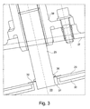
- the Fig. 2 to 4 each show in a schematic representation of a combustion chamber housing 37 to which an adapter 38 is attached to store a spark plug 25. This passes through a recess 31, an outer combustion chamber wall 29 and an inner combustion chamber wall 30.
- the combustion chamber interior is designated by the reference numeral 33.
- combustion chambers are designed to be round as annular combustion chambers or individual combustion chambers, so that no flat surface of the outer combustion chamber wall 29 results. Due to the flexible design of the sealing ring 32, however, this can rest sealingly around its entire circumference.
- a contact element 36 which is formed for example in the form of a snap ring, which is introduced into a groove of the spark plug 25.
- a contact element 36 which is formed for example in the form of a snap ring, which is introduced into a groove of the spark plug 25.
- the abutment member 36 is welded, for example in the form of sections or segments which extend around the circumference of the spark plug 25.
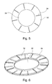
- the Fig. 5 shows a plan view of the sealing ring according to the invention. It can be seen that this distributed around its circumference with a plurality of slots 34th is provided, which extend in particular at the edge region of the sealing ring 32.
- the reference numeral 35 shows the central recess of the sealing ring 32nd
- Fig. 6 shows an arrangement of two sealing rings on top of each other, wherein it can be seen that the individual slots 34 are circumferentially offset from one another in order to optimize the seal.
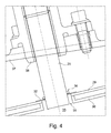
- Fig. 7 is a design variant too Fig. 2 shown in which no contact element 36 is required in the form of a separate snap ring.
- the abutment element is formed by an elongated adapter 39, which secures the sealing ring 32 against falling.
- the adapter 39 in the embodiment shown is positioned between the spark plug adapter 38 and the combustion chamber wall 29.
- the adapter 38 of the spark plug and the adapter 39 are integrated into one component, in particular when the distance between the combustion chamber housing 37 and the outer combustion chamber wall 29 is optimized and / or reduced.
Abstract
Die Erfindung bezieht sich auf eine Dichtungsanordnung einer Zündkerze 25 einer Brennkammer 15 einer Gasturbine, mit einer Zündkerze 25, welche durch eine Ausnehmung 31 einer Brennkammerwand 29, 30 angeordnet ist, mit zumindest einem Dichtring 32, durch welchen die Zündkerze 25 ragt und welche gegen einen dem Brennkammerinnenraum 33 abgewandten Randbereich der Ausnehmung 31 dichtend anliegt, dadurch gekennzeichnet, dass der Dichtring 32 in Form einer flachen, ringförmigen, flexiblen Scheibe ausgebildet ist.The invention relates to a sealing arrangement of a spark plug 25 of a combustion chamber 15 of a gas turbine, with a spark plug 25, which is arranged through a recess 31 of a combustion chamber wall 29, 30, with at least one sealing ring 32 through which the spark plug 25 projects and which against a the combustion chamber interior 33 remote from the edge region of the recess 31 sealingly abuts, characterized in that the sealing ring 32 is formed in the form of a flat, annular, flexible disk.
Description
Die Erfindung bezieht sich auf eine Dichtungsanordnung gemäß dem Oberbegriff des Anspruchs 1.The invention relates to a sealing arrangement according to the preamble of
Im Einzelnen bezieht sich die Erfindung auf eine Dichtungsanordnung einer Zündkerze oder einer Messsonde oder eines ähnlichen Bauteils, welches durch eine Brennkammerwand einer Gasturbine geführt ist. Im Nachfolgenden wird stets der Begriff Zündkerze verwendet, dies ist jedoch nicht einschränkend zu verstehen.In detail, the invention relates to a sealing arrangement of a spark plug or a measuring probe or a similar component, which is guided through a combustion chamber wall of a gas turbine. In the following, the term spark plug is always used, but this is not to be understood as limiting.
Die erfindungsgemäße Dichtungsanordnung umfasst zumindest einen Dichtring, durch welchen die Zündkerze oder die Messsonde ragt und welche gegen einen dem Brennkammerinnenraum abgewandten Randbereich der Ausnehmung dichtend anliegt. Eine Ausgestaltung dieser Art ist beispielsweise aus der
Zum Abdichten des Ringspaltes sind aus dem Stand der Technik unterschiedliche Lösungen vorbekannt. Hierzu wird auf die
Wird auf eine Abdichtung der Eintrittsöffnung für die Zündkerze verzichtet, so wird Luft um die Zündkerze herum in die Brennkammer geleitet. Aufgrund der geänderten Geometrie im Vergleich zu den sonstigen Mischluftlöchern in der Brennkammer ergibt sich ein unterschiedlicher Luftstrom. Dieser beeinflusst die Verbrennung sowie die Kühlung der Brennkammerinnenwand in diesem Bereich. Durch geänderte Temperaturverteilungen ergeben sich lokale Überhitzungen oder ein erhöhter Kühlluftbedarf.If a sealing of the inlet opening for the spark plug is dispensed with, air is conducted around the spark plug into the combustion chamber. Due to the changed geometry compared to the other mixing air holes in the combustion chamber results in a different air flow. This influences the combustion as well as the cooling of the combustion chamber inner wall in this area. Changing the temperature distribution results in local overheating or an increased need for cooling air.
Bei der Verwendung der oben genannten röhrenartigen Ausgestaltungen ergibt sich zusätzlich zu dem erhöhten Fertigungsaufwand und den höheren Kosten der Nachteil, dass der Luftstrom um die Brennkammerwand lokal beeinflusst wird. Dies beeinflusst auch den Luftstrom durch die in der Nähe der Zündkerze befindlichen Mischluftöffnungen und Kühlluftbohrungen. Als Folge hieraus ergibt sich eine unterschiedliche Verbrennung und Kühlung im Bereich sowohl des Zündkerzeneintritts als auch der benachbarten Mischluftlöcher. Dies führt, wie erwähnt, zu lokalen Überhitzungen und erhöhtem Kühlluftbedarf.When using the above-mentioned tube-like embodiments, in addition to the increased production costs and the higher costs, there is the disadvantage that the air flow around the combustion chamber wall is influenced locally. This also affects airflow through the mixed air openings and cooling air holes located near the spark plug. As a result, there is a different combustion and cooling in the area of both the spark plug inlet and the adjacent mixing air holes. This leads, as mentioned, to local overheating and increased cooling air requirements.
Hinsichtlich des erhöhten Fertigungsaufwandes ist zu berücksichtigen, dass bei beengten Platzverhältnissen die röhrenartigen Abdichtungen von der Brennkammerinnenseite aus befestigt werden müssen, beispielsweise durch Schweißen. Dies erfordert eine manuelle Nacharbeit der Innenseite der Brennkammerwand, um eine ausreichende Abdichtung sicherzustellen.With regard to the increased production costs, it should be borne in mind that in tight spaces, the tubular seals must be fastened from the inside of the combustion chamber, for example by welding. This requires manual reworking of the inside of the combustion chamber wall to ensure adequate sealing.
Bei einer Verwendung eines beweglichen Dichtrings zwischen der äußeren und der inneren Brennkammerwand, welcher in den Zwischenraum eingeklemmt wird, so wie dies beispielsweise die
Der Erfindung liegt die Aufgabe zugrunde, eine Dichtungsanordnung der eingangs genannten Art zu schaffen, welche bei einfachem Aufbau und einfacher, kostengünstiger Herstellbarkeit die Nachteile des Standes der Technik vermeidet und zu einer optimierten Abdichtung führt.The invention has for its object to provide a seal assembly of the type mentioned, which avoids the disadvantages of the prior art with a simple structure and simple, cost-effective manufacturability and leads to an optimized seal.
Erfindungsgemäß wird die Aufgabe durch die Merkmalskombination des Anspruchs 1 gelöst, die Unteransprüche zeigen weitere vorteilhafte Ausgestaltungen der Erfindung.According to the invention the object is achieved by the combination of features of
Erfindungsgemäß ist somit vorgesehen, dass der Dichtring in Form einer flachen, ringförmigen, flexiblen Scheibe ausgebildet ist. Diese ist bevorzugterweise als Blechbauteil ausgebildet.According to the invention it is thus provided that the sealing ring is designed in the form of a flat, annular, flexible disc. This is preferably designed as a sheet metal component.
Ein wesentlicher Vorteil der erfindungsgemäßen Ausgestaltung liegt darin, dass sich ein erheblich reduzierter Fertigungsaufwand ergibt. Weiterhin werden sowohl die Kühlluftführung als auch die Mischluftführung nur minimal beeinflusst, da die erfindungsgemäße Dichtungsanordnung einen sehr geringen Bauraum erfordert.A significant advantage of the embodiment of the invention is that there is a significantly reduced manufacturing costs. Furthermore, both the cooling air flow and the mixed air flow are only minimally influenced, since the sealing arrangement according to the invention requires a very small installation space.
Der erfindungsgemäß vorgesehene Dichtring kann, da es sich um ein flaches, leichtes Bauteil handelt, durch den Druckunterschied zwischen der Außenseite der Brennkammerwand und der Innenseite der Brennkammerwand gegen die Brennkammerwand angelegt und dichtend gehalten werden. Es ist nicht erforderlich, zusätzliche Maßnahmen zu ergreifen, um den Dichtring gegen die Brennkammerwand vorzuspannen oder zu fixieren. Im Betrieb der Gasturbine liegt somit der Dichtring an der Außenseite der Brennkammerwand an und reduziert hierdurch den Leckageluftstrom.The inventively provided sealing ring, since it is a flat, lightweight component can be created by the pressure difference between the outside of the combustion chamber wall and the inside of the combustion chamber wall against the combustion chamber wall and kept sealed. It is not necessary to take additional measures to bias or fix the sealing ring against the combustion chamber wall. During operation of the gas turbine thus the sealing ring is located on the outside of the combustion chamber wall and thereby reduces the leakage air flow.
In besonders günstiger Ausgestaltung der Erfindung ist der Dichtring mit radialen, bezogen auf seine mittige Ausnehmung zur Durchführung der Zündkerze, Schlitzen versehen. Diese Schlitze führen zu einer erheblichen Erhöhung der Flexibilität des Dichtrings, sodass dieser auch auf nicht-ebenen Bereichen der Brennkammerwand dichtend aufliegt.In a particularly advantageous embodiment of the invention, the sealing ring with radial, relative to its central recess for carrying out the spark plug, slots provided. These slots lead to a considerable increase in the flexibility of the sealing ring, so that it rests sealingly on non-planar areas of the combustion chamber wall.
In besonders günstiger Weiterbildung der Erfindung ist vorgesehen, dass mehrere Dichtringe übereinanderliegend vorgesehen sind. Diese mehreren Dichtringe können bevorzugterweise miteinander verbunden werden, beispielsweise über eine Punktschweißung. Weiterhin kann es günstig sein, die Schlitze der mehreren Dichtringe in Umfangsrichtung, bezogen auf den Dichtring, zueinander versetzt anzuordnen. Hierdurch ergibt sich eine besonders gute Abdichtung.In a particularly favorable development of the invention it is provided that a plurality of sealing rings are provided one above the other. These multiple sealing rings can are preferably interconnected, for example via a spot weld. Furthermore, it may be advantageous to arrange the slots of the plurality of sealing rings in the circumferential direction, relative to the sealing ring, offset from each other. This results in a particularly good seal.
Zündkerzen sind oft im unteren Bereich des Triebwerks angeordnet. Der Dichtring würde somit insbesondere im Stillstand der Fluggasturbine am Brennkammergehäuse anliegen. Um den Dichtring mechanisch in die Nähe der Brennkammerwand zu bringen und um sicherzustellen, dass beim Betrieb der Gasturbine der Dichtring durch die Druckdifferenz gegen die Brennkammerwand angedrückt wird, ist es besonders günstig, wenn die Zündkerze mit zumindest einem den Dichtring abstützenden Anlageelement versehen ist. Das Anlageelement kann als Sicherungsring oder als Adapter ausgebildet sein. In beiden Fällen kann das Anlageelement direkt an der Zündkerze vorgesehen sein. Es ist auch möglich, das Anlageelement direkt bei der Herstellung des Adapters bzw. der Zündkerze auszubilden oder Anlageelemente oder Distanzstücke an der Zündkerze vorzusehen, beispielsweise durch Anschweißen.Spark plugs are often located in the lower part of the engine. The sealing ring would thus rest against the combustion chamber housing, in particular when the aircraft gas turbine is at a standstill. To mechanically bring the sealing ring in the vicinity of the combustion chamber wall and to ensure that during operation of the gas turbine, the sealing ring is pressed by the pressure difference against the combustion chamber wall, it is particularly advantageous if the spark plug is provided with at least one bearing element supporting the sealing ring. The contact element can be designed as a retaining ring or as an adapter. In both cases, the contact element can be provided directly on the spark plug. It is also possible to form the abutment element directly in the manufacture of the adapter or the spark plug or to provide abutment elements or spacers on the spark plug, for example by welding.
In besonders günstiger Weiterbildung der Erfindung ist vorgesehen, dass der Dichtring durch einen rohrförmigen, verlängert ausgebildeten Adapter gesichert wird. Dieser wird außerhalb des Dichtrings positioniert. Dabei kann die Zündkerze durch den verlängerten Adapter durchgeführt werden. Es sind somit keine Änderungen an der Zündkerze selbst erforderlich. Der zusätzliche, rohrförmige Adapter stützt sich dabei an seinem, bezogen auf die Triebwerksmittelachse, radial äußeren Bereich gegen den Adapter ab, mit dem die Zündkerze selbst an dem Brennkammergehäuse befestigt ist. Es wird somit in betriebssicherer Weise sichergestellt, dass der Dichtring oder die mehreren Dichtringe exakt positioniert sind.In a particularly favorable development of the invention it is provided that the sealing ring is secured by a tubular, elongated adapter. This is positioned outside the sealing ring. The spark plug can be carried out through the extended adapter. There are thus no changes to the spark plug itself required. The additional, tubular adapter is supported on its, relative to the engine central axis, radially outer region against the adapter, with which the spark plug itself is attached to the combustion chamber housing. It is thus ensured in a reliable manner that the sealing ring or the plurality of sealing rings are accurately positioned.
Erfindungsgemäß ergibt sich somit ein einfacher, kostengünstiger Aufbau der gesamten Dichtungsanordnung. Diese übt wenig Einfluss auf die Kühlung in der Nähe der Mischluftöffnungen aus und zeichnet sich insbesondere durch eine geringe Bauhöhe aus.According to the invention thus results in a simple, inexpensive construction of the entire seal assembly. This exerts little influence on the cooling in the vicinity of the mixed air openings and is characterized in particular by a low height.
Im Folgenden wird die Erfindung anhand von Ausführungsbeispielen in Verbindung mit der Zeichnung beschrieben. Dabei zeigt:
- Fig. 1
- eine schematische Darstellung eines Gasturbinentriebwerks gemäß der vorliegenden Erfindung,
- Fig. 2 - 4
- vereinfachte Seiten-Schnittansichten von Ausführungsbeispielen der erfindungsgemäßen Dichtungsanordnung,
- Fig. 5
- eine Draufsicht auf ein Ausführungsbeispiel des erfindungsgemäßen Dichtrings,
- Fig. 6
- eine perspektivische Darstellung zweier übereinander gelegter Dichtringe, und
- Fig. 7
- ein abgewandeltes Ausführungsbeispiel analog
Fig. 2 .
- Fig. 1
- a schematic representation of a gas turbine engine according to the present invention,
- Fig. 2-4
- simplified side sectional views of embodiments of the seal assembly according to the invention,
- Fig. 5
- a top view of an embodiment of the sealing ring according to the invention,
- Fig. 6
- a perspective view of two superimposed sealing rings, and
- Fig. 7
- a modified embodiment analog
Fig. 2 ,
Das Gasturbinentriebwerk 10 gemäß
Der Mitteldruckkompressor 13 und der Hochdruckkompressor 14 umfassen jeweils mehrere Stufen, von denen jede eine in Umfangsrichtung verlaufende Anordnung fester stationärer Leitschaufeln 20 aufweist, die allgemein als Statorschaufeln bezeichnet werden und die radial nach innen vom Triebwerksgehäuse 21 in einem ringförmigen Strömungskanal durch die Kompressoren 13, 14 vorstehen. Die Kompressoren weisen weiter eine Anordnung von Kompressorlaufschaufeln 22 auf, die radial nach außen von einer drehbaren Trommel oder Scheibe 26 vorstehen, die mit Naben 27 der Hochdruckturbine 16 bzw. der Mitteldruckturbine 17 gekoppelt sind.The intermediate-
Die Turbinenabschnitte 16, 17, 18 weisen ähnliche Stufen auf, umfassend eine Anordnung von festen Leitschaufeln 23, die radial nach innen vom Gehäuse 21 in den ringförmigen Strömungskanal durch die Turbinen 16, 17, 18 vorstehen, und eine nachfolgende Anordnung von Turbinenschaufeln 24, die nach außen von einer drehbaren Nabe 27 vorstehen. Die Kompressortrommel oder Kompressorscheibe 26 und die darauf angeordneten Schaufeln 22 sowie die Turbinenrotornabe 27 und die darauf angeordneten Turbinenlaufschaufeln 24 drehen sich im Betrieb um die Triebwerksmittelachse 1.The
Die
An der Außenseite, abgewandt von dem Brennkammerinnenraum 33 liegt ein flacher, ringförmiger, flexibler Dichtring 32 gegen die äußere Brennkammerwand 29 an und wird durch den Druckunterschied zwischen der Außenseite und der Innenseite der Brennkammerwand 29, 30 in dichtende Anlage gebracht. Es versteht sich, dass Brennkammern als Ringbrennkammern oder Einzelbrennkammern rund ausgebildet sind, sodass sich keine ebene Fläche der äußeren Brennkammerwand 29 ergibt. Durch die flexible Ausgestaltung des Dichtrings 32 kann dieser jedoch um seinen gesamten Umfang dichtend anliegen.On the outside, facing away from the
Um eine Sicherung des Dichtrings 32 im nicht in Betrieb befindlichen Zustand der Gasturbine sicherzustellen, weist das Ausführungsbeispiel der
Die
Die
In
- 11
- TriebwerksmittelachseEngine centerline axis
- 1010
- Gasturbinentriebwerk / KerntriebwerkGas turbine engine / core engine
- 1111
- Lufteinlassair intake
- 1212
- Fanfan
- 1313
- Mitteldruckkompressor (Verdichter)Medium pressure compressor (compressor)
- 1414
- HochdruckkompressorHigh pressure compressor
- 1515
- Brennkammercombustion chamber
- 1616
- HochdruckturbineHigh-pressure turbine
- 1717
- MitteldruckturbineIntermediate pressure turbine
- 1818
- NiederdruckturbineLow-pressure turbine
- 1919
- Abgasdüseexhaust nozzle
- 2020
- Leitschaufelnvanes
- 2121
- Kern-TriebwerksgehäuseCore engine casing
- 2222
- KompressorlaufschaufelnCompressor blades
- 2323
- Leitschaufelnvanes
- 2424
- Turbinenschaufelnturbine blades
- 2525
- Zündkerzespark plug
- 2626
- Komressortrommel oder -ScheibeCompressor drum or disc
- 2727
- TurbinenrotornabeTurbinenrotornabe
- 2828
- Auslasskonusoutlet cone
- 2929
- äußere Brennkammerwandouter combustion chamber wall
- 3030
- innere Brennkammerwandinner combustion chamber wall
- 3131
- Ausnehmungrecess
- 3232
- Dichtringseal
- 3333
- BrennkammerinnenraumCombustion chamber interior
- 3434
- Schlitzslot
- 3535
- mittige Ausnehmungcentral recess
- 3636
- Anlageelementcontact element
- 3737
- Brennkammergehäusecombustion chamber housing
- 3838
- Adapteradapter
- 3939
- Adapteradapter
Claims (10)
Applications Claiming Priority (1)
| Application Number | Priority Date | Filing Date | Title |
|---|---|---|---|
| DE102014214775.1A DE102014214775A1 (en) | 2014-07-28 | 2014-07-28 | Aircraft gas turbine with a seal for sealing a spark plug on the combustion chamber wall of a gas turbine |
Publications (1)
| Publication Number | Publication Date |
|---|---|
| EP2980481A1 true EP2980481A1 (en) | 2016-02-03 |
Family
ID=53610823
Family Applications (1)
| Application Number | Title | Priority Date | Filing Date |
|---|---|---|---|
| EP15176991.6A Withdrawn EP2980481A1 (en) | 2014-07-28 | 2015-07-16 | Aircraft gas turbine having a seal for sealing a spark plug to the combustor chamber wall of a gas turbine |
Country Status (3)
| Country | Link |
|---|---|
| US (1) | US9982783B2 (en) |
| EP (1) | EP2980481A1 (en) |
| DE (1) | DE102014214775A1 (en) |
Families Citing this family (3)
| Publication number | Priority date | Publication date | Assignee | Title |
|---|---|---|---|---|
| US11242804B2 (en) | 2017-06-14 | 2022-02-08 | General Electric Company | Inleakage management apparatus |
| GB201804656D0 (en) | 2018-03-23 | 2018-05-09 | Rolls Royce Plc | An igniter seal arrangement for a combustion chamber |
| US20230383667A1 (en) * | 2022-05-31 | 2023-11-30 | Pratt & Whitney Canada Corp. | Joint between gas turbine engine components with bonded fastener(s) |
Citations (8)
| Publication number | Priority date | Publication date | Assignee | Title |
|---|---|---|---|---|
| US6351949B1 (en) * | 1999-09-03 | 2002-03-05 | Allison Advanced Development Company | Interchangeable combustor chute |
| US20030163995A1 (en) | 2002-03-04 | 2003-09-04 | White Tracy Lowell | Apparatus for positioning an igniter within a liner port of a gas turbine engine |
| EP1489360A1 (en) * | 2003-06-20 | 2004-12-22 | Snecma Moteurs | Gasket assembly for igniter tube non-welded to the chamber wall |
| US20050072163A1 (en) | 2003-01-14 | 2005-04-07 | Wells Thomas Allen | Mounting assembly for igniter in a gas turbine engine combustor having a ceramic matrix composite liner |
| GB2445576A (en) | 2007-01-11 | 2008-07-16 | Rolls Royce Plc | Igniter plug housing arrangement |
| US20090235635A1 (en) * | 2008-03-21 | 2009-09-24 | Siemens Power Generation, Inc. | Igniter Assembly for a Gas Turbine |
| US20110120132A1 (en) | 2009-11-23 | 2011-05-26 | Honeywell International Inc. | Dual walled combustors with impingement cooled igniters |
| US20130055716A1 (en) | 2011-04-13 | 2013-03-07 | Rolls-Royce Deutschland Ltd & Co Kg | Gas-turbine combustion chamber with a holding means of a seal for an attachment |
Family Cites Families (15)
| Publication number | Priority date | Publication date | Assignee | Title |
|---|---|---|---|---|
| US3922851A (en) * | 1974-04-05 | 1975-12-02 | Gen Motors Corp | Combustor liner support |
| GB1602836A (en) * | 1977-05-11 | 1981-11-18 | Lucas Industries Ltd | Sealing arrangement for use in a combustion assembly |
| US5356158A (en) * | 1990-10-11 | 1994-10-18 | Rotoflex, Inc. | Resilient rotary seal with projecting edge |
| US5085250A (en) * | 1990-12-18 | 1992-02-04 | Daniel Industries, Inc. | Orifice system |
| DE29823424U1 (en) * | 1997-11-17 | 1999-06-24 | Allweiler Ag | Centrifugal pump with mechanical seal |
| GB0227842D0 (en) * | 2002-11-29 | 2003-01-08 | Rolls Royce Plc | Sealing Arrangement |
| GB2396687A (en) * | 2002-12-23 | 2004-06-30 | Rolls Royce Plc | Helmholtz resonator for combustion chamber use |
| JP4091874B2 (en) * | 2003-05-21 | 2008-05-28 | 本田技研工業株式会社 | Secondary air supply device for gas turbine engine |
| US7017334B2 (en) * | 2003-12-18 | 2006-03-28 | United Technologies Corporation | Compact fastening collar and stud for connecting walls of a nozzle liner and method associated therewith |
| ITMI20041778A1 (en) * | 2004-09-17 | 2004-12-17 | Nuovo Pignone Spa | BOTTOM SEALED BOTTOM FOR A DOUBLE SHAFT TURBINE |
| US7497443B1 (en) * | 2005-05-03 | 2009-03-03 | The United States Of America As Represented By The Administrator Of The National Aeronautics And Space Administration | Resilient flexible pressure-activated seal |
| US8196934B2 (en) * | 2007-01-10 | 2012-06-12 | United Technologies Corporation | Slider seal assembly for gas turbine engine |
| FR2953908A1 (en) * | 2009-12-16 | 2011-06-17 | Snecma | GUIDING A CANDLE IN A TURBOMACHINE COMBUSTION CHAMBER |
| US20190162306A9 (en) * | 2011-06-17 | 2019-05-30 | The Patent Well LLC | Polyurea gasket and gasket tape and a method of making and using the same |
| US9038395B2 (en) * | 2012-03-29 | 2015-05-26 | Honeywell International Inc. | Combustors with quench inserts |
-
2014
- 2014-07-28 DE DE102014214775.1A patent/DE102014214775A1/en not_active Withdrawn
-
2015
- 2015-07-16 EP EP15176991.6A patent/EP2980481A1/en not_active Withdrawn
- 2015-07-28 US US14/811,131 patent/US9982783B2/en not_active Expired - Fee Related
Patent Citations (8)
| Publication number | Priority date | Publication date | Assignee | Title |
|---|---|---|---|---|
| US6351949B1 (en) * | 1999-09-03 | 2002-03-05 | Allison Advanced Development Company | Interchangeable combustor chute |
| US20030163995A1 (en) | 2002-03-04 | 2003-09-04 | White Tracy Lowell | Apparatus for positioning an igniter within a liner port of a gas turbine engine |
| US20050072163A1 (en) | 2003-01-14 | 2005-04-07 | Wells Thomas Allen | Mounting assembly for igniter in a gas turbine engine combustor having a ceramic matrix composite liner |
| EP1489360A1 (en) * | 2003-06-20 | 2004-12-22 | Snecma Moteurs | Gasket assembly for igniter tube non-welded to the chamber wall |
| GB2445576A (en) | 2007-01-11 | 2008-07-16 | Rolls Royce Plc | Igniter plug housing arrangement |
| US20090235635A1 (en) * | 2008-03-21 | 2009-09-24 | Siemens Power Generation, Inc. | Igniter Assembly for a Gas Turbine |
| US20110120132A1 (en) | 2009-11-23 | 2011-05-26 | Honeywell International Inc. | Dual walled combustors with impingement cooled igniters |
| US20130055716A1 (en) | 2011-04-13 | 2013-03-07 | Rolls-Royce Deutschland Ltd & Co Kg | Gas-turbine combustion chamber with a holding means of a seal for an attachment |
Also Published As
| Publication number | Publication date |
|---|---|
| DE102014214775A1 (en) | 2016-01-28 |
| US20160025221A1 (en) | 2016-01-28 |
| US9982783B2 (en) | 2018-05-29 |
Similar Documents
| Publication | Publication Date | Title |
|---|---|---|
| EP3056813B1 (en) | Seal of an edge gap between effusion shingle of a gas turbine combustor | |
| EP2503246B1 (en) | Segmented combustion chamber head | |
| EP3239612B1 (en) | Gas turbine combustor | |
| EP1471211B1 (en) | Sealing arrangement between stator blades and rotor of a high pressure turbine | |
| EP2738470B1 (en) | Shingle attachment assembly of a gas turbine combustion chamber | |
| EP2927594B1 (en) | Combustion chamber of a gas turbine | |
| EP3115691A1 (en) | Gas turbine combustor with integrated turbine inlet guide vane and method for the production thereof | |
| EP2824282A1 (en) | Gas turbine with high pressure turbine cooling system | |
| EP2921778A1 (en) | Combustion chamber of a gas turbine | |
| EP2918913B1 (en) | Combustion chamber of a gas turbine | |
| DE102015201782A1 (en) | Guide vane ring for a turbomachine | |
| EP2647795A1 (en) | Seal system for a turbo engine | |
| EP2503242B1 (en) | Combustion chamber head with holder for burner seals in gas turbines | |
| EP2799776A1 (en) | Burner seal for gas turbine combustion chamber head and heat shield | |
| EP2966352A1 (en) | Combustion chamber of a gas turbine with screwed combustion chamber head | |
| DE102014204476A1 (en) | Combustion chamber of a gas turbine | |
| EP2980481A1 (en) | Aircraft gas turbine having a seal for sealing a spark plug to the combustor chamber wall of a gas turbine | |
| EP2474744A1 (en) | Annular flow channel for an axial compressor | |
| EP2526263B1 (en) | Housing system for an axial turbomachine | |
| EP3321589B1 (en) | Fuel nozzle of a gas turbine with swirl creator | |
| EP2955336B1 (en) | Intermediate housing for a gas turbine and gas turbine with such an intermediate housing | |
| EP2611992B1 (en) | Housing structure of a turbomachine | |
| EP2725203B1 (en) | Cool air guide in a housing structure of a fluid flow engine | |
| DE102014222320A1 (en) | Combustion chamber wall of a gas turbine with cooling for a mixed air hole edge | |
| EP3179169B1 (en) | Method for mounting a combustion chamber of a gas turbine engine |
Legal Events
| Date | Code | Title | Description |
|---|---|---|---|
| PUAI | Public reference made under article 153(3) epc to a published international application that has entered the european phase |
Free format text: ORIGINAL CODE: 0009012 |
|
| AK | Designated contracting states |
Kind code of ref document: A1 Designated state(s): AL AT BE BG CH CY CZ DE DK EE ES FI FR GB GR HR HU IE IS IT LI LT LU LV MC MK MT NL NO PL PT RO RS SE SI SK SM TR |
|
| AX | Request for extension of the european patent |
Extension state: BA ME |
|
| 17P | Request for examination filed |
Effective date: 20160323 |
|
| RBV | Designated contracting states (corrected) |
Designated state(s): AL AT BE BG CH CY CZ DE DK EE ES FI FR GB GR HR HU IE IS IT LI LT LU LV MC MK MT NL NO PL PT RO RS SE SI SK SM TR |
|
| 17Q | First examination report despatched |
Effective date: 20200123 |
|
| STAA | Information on the status of an ep patent application or granted ep patent |
Free format text: STATUS: THE APPLICATION HAS BEEN WITHDRAWN |
|
| 18W | Application withdrawn |
Effective date: 20200528 |