EP2980428A1 - Oil supply device for linear guide device, and linear guide device - Google Patents
Oil supply device for linear guide device, and linear guide device Download PDFInfo
- Publication number
- EP2980428A1 EP2980428A1 EP14776389.0A EP14776389A EP2980428A1 EP 2980428 A1 EP2980428 A1 EP 2980428A1 EP 14776389 A EP14776389 A EP 14776389A EP 2980428 A1 EP2980428 A1 EP 2980428A1
- Authority
- EP
- European Patent Office
- Prior art keywords
- end cap
- container
- linear guide
- lubricant
- direction change
- Prior art date
- Legal status (The legal status is an assumption and is not a legal conclusion. Google has not performed a legal analysis and makes no representation as to the accuracy of the status listed.)
- Withdrawn
Links
- 239000000314 lubricant Substances 0.000 claims abstract description 113
- 238000005096 rolling process Methods 0.000 claims abstract description 58
- 230000001050 lubricating effect Effects 0.000 claims description 67
- 238000000465 moulding Methods 0.000 claims description 3
- 238000000034 method Methods 0.000 description 22
- 239000000463 material Substances 0.000 description 7
- 229920000098 polyolefin Polymers 0.000 description 7
- 229920006324 polyoxymethylene Polymers 0.000 description 6
- 239000004743 Polypropylene Substances 0.000 description 4
- 230000002146 bilateral effect Effects 0.000 description 4
- 230000007547 defect Effects 0.000 description 4
- 230000000694 effects Effects 0.000 description 4
- 229920001155 polypropylene Polymers 0.000 description 4
- 229920005989 resin Polymers 0.000 description 4
- 239000011347 resin Substances 0.000 description 4
- -1 polypropylene Polymers 0.000 description 3
- 230000000717 retained effect Effects 0.000 description 3
- 239000004952 Polyamide Substances 0.000 description 2
- 230000005611 electricity Effects 0.000 description 2
- 239000012634 fragment Substances 0.000 description 2
- 210000004209 hair Anatomy 0.000 description 2
- 238000005461 lubrication Methods 0.000 description 2
- 239000002184 metal Substances 0.000 description 2
- 229910052751 metal Inorganic materials 0.000 description 2
- 229920002647 polyamide Polymers 0.000 description 2
- 230000003068 static effect Effects 0.000 description 2
- 241001465754 Metazoa Species 0.000 description 1
- 239000004677 Nylon Substances 0.000 description 1
- 241001494479 Pecora Species 0.000 description 1
- 229930182556 Polyacetal Natural products 0.000 description 1
- 239000004698 Polyethylene Substances 0.000 description 1
- 239000004721 Polyphenylene oxide Substances 0.000 description 1
- 229920000297 Rayon Polymers 0.000 description 1
- 238000010521 absorption reaction Methods 0.000 description 1
- 239000004760 aramid Substances 0.000 description 1
- 229920003235 aromatic polyamide Polymers 0.000 description 1
- 229920002678 cellulose Polymers 0.000 description 1
- 239000001913 cellulose Substances 0.000 description 1
- 239000000356 contaminant Substances 0.000 description 1
- 230000006866 deterioration Effects 0.000 description 1
- 230000008030 elimination Effects 0.000 description 1
- 238000003379 elimination reaction Methods 0.000 description 1
- 238000004299 exfoliation Methods 0.000 description 1
- 239000011521 glass Substances 0.000 description 1
- 230000005484 gravity Effects 0.000 description 1
- 239000004519 grease Substances 0.000 description 1
- 238000009413 insulation Methods 0.000 description 1
- 239000010687 lubricating oil Substances 0.000 description 1
- 238000012423 maintenance Methods 0.000 description 1
- 150000002739 metals Chemical class 0.000 description 1
- 229920001778 nylon Polymers 0.000 description 1
- 229920000728 polyester Polymers 0.000 description 1
- 229920000570 polyether Polymers 0.000 description 1
- 229920000573 polyethylene Polymers 0.000 description 1
- 239000002861 polymer material Substances 0.000 description 1
- 230000003252 repetitive effect Effects 0.000 description 1
- 238000007789 sealing Methods 0.000 description 1
- 239000007779 soft material Substances 0.000 description 1
- 239000000126 substance Substances 0.000 description 1
- 229920003002 synthetic resin Polymers 0.000 description 1
- 239000000057 synthetic resin Substances 0.000 description 1
- 210000002268 wool Anatomy 0.000 description 1
Images




Classifications
-
- F—MECHANICAL ENGINEERING; LIGHTING; HEATING; WEAPONS; BLASTING
- F16—ENGINEERING ELEMENTS AND UNITS; GENERAL MEASURES FOR PRODUCING AND MAINTAINING EFFECTIVE FUNCTIONING OF MACHINES OR INSTALLATIONS; THERMAL INSULATION IN GENERAL
- F16C—SHAFTS; FLEXIBLE SHAFTS; ELEMENTS OR CRANKSHAFT MECHANISMS; ROTARY BODIES OTHER THAN GEARING ELEMENTS; BEARINGS
- F16C33/00—Parts of bearings; Special methods for making bearings or parts thereof
- F16C33/30—Parts of ball or roller bearings
- F16C33/66—Special parts or details in view of lubrication
-
- F—MECHANICAL ENGINEERING; LIGHTING; HEATING; WEAPONS; BLASTING
- F16—ENGINEERING ELEMENTS AND UNITS; GENERAL MEASURES FOR PRODUCING AND MAINTAINING EFFECTIVE FUNCTIONING OF MACHINES OR INSTALLATIONS; THERMAL INSULATION IN GENERAL
- F16N—LUBRICATING
- F16N7/00—Arrangements for supplying oil or unspecified lubricant from a stationary reservoir or the equivalent in or on the machine or member to be lubricated
- F16N7/12—Arrangements for supplying oil or unspecified lubricant from a stationary reservoir or the equivalent in or on the machine or member to be lubricated with feed by capillary action, e.g. by wicks
-
- F—MECHANICAL ENGINEERING; LIGHTING; HEATING; WEAPONS; BLASTING
- F16—ENGINEERING ELEMENTS AND UNITS; GENERAL MEASURES FOR PRODUCING AND MAINTAINING EFFECTIVE FUNCTIONING OF MACHINES OR INSTALLATIONS; THERMAL INSULATION IN GENERAL
- F16C—SHAFTS; FLEXIBLE SHAFTS; ELEMENTS OR CRANKSHAFT MECHANISMS; ROTARY BODIES OTHER THAN GEARING ELEMENTS; BEARINGS
- F16C29/00—Bearings for parts moving only linearly
- F16C29/04—Ball or roller bearings
- F16C29/06—Ball or roller bearings in which the rolling bodies circulate partly without carrying load
- F16C29/0602—Details of the bearing body or carriage or parts thereof, e.g. methods for manufacturing or assembly
- F16C29/0609—Details of the bearing body or carriage or parts thereof, e.g. methods for manufacturing or assembly of the ends of the bearing body or carriage where the rolling elements change direction, e.g. end caps
-
- F—MECHANICAL ENGINEERING; LIGHTING; HEATING; WEAPONS; BLASTING
- F16—ENGINEERING ELEMENTS AND UNITS; GENERAL MEASURES FOR PRODUCING AND MAINTAINING EFFECTIVE FUNCTIONING OF MACHINES OR INSTALLATIONS; THERMAL INSULATION IN GENERAL
- F16C—SHAFTS; FLEXIBLE SHAFTS; ELEMENTS OR CRANKSHAFT MECHANISMS; ROTARY BODIES OTHER THAN GEARING ELEMENTS; BEARINGS
- F16C33/00—Parts of bearings; Special methods for making bearings or parts thereof
- F16C33/30—Parts of ball or roller bearings
- F16C33/66—Special parts or details in view of lubrication
- F16C33/6637—Special parts or details in view of lubrication with liquid lubricant
- F16C33/6659—Details of supply of the liquid to the bearing, e.g. passages or nozzles
-
- F—MECHANICAL ENGINEERING; LIGHTING; HEATING; WEAPONS; BLASTING
- F16—ENGINEERING ELEMENTS AND UNITS; GENERAL MEASURES FOR PRODUCING AND MAINTAINING EFFECTIVE FUNCTIONING OF MACHINES OR INSTALLATIONS; THERMAL INSULATION IN GENERAL
- F16N—LUBRICATING
- F16N19/00—Lubricant containers for use in lubricators or lubrication systems
-
- F—MECHANICAL ENGINEERING; LIGHTING; HEATING; WEAPONS; BLASTING
- F16—ENGINEERING ELEMENTS AND UNITS; GENERAL MEASURES FOR PRODUCING AND MAINTAINING EFFECTIVE FUNCTIONING OF MACHINES OR INSTALLATIONS; THERMAL INSULATION IN GENERAL
- F16N—LUBRICATING
- F16N21/00—Conduits; Junctions; Fittings for lubrication apertures
- F16N21/06—Covering members for nipples, conduits or apertures
-
- F—MECHANICAL ENGINEERING; LIGHTING; HEATING; WEAPONS; BLASTING
- F16—ENGINEERING ELEMENTS AND UNITS; GENERAL MEASURES FOR PRODUCING AND MAINTAINING EFFECTIVE FUNCTIONING OF MACHINES OR INSTALLATIONS; THERMAL INSULATION IN GENERAL
- F16C—SHAFTS; FLEXIBLE SHAFTS; ELEMENTS OR CRANKSHAFT MECHANISMS; ROTARY BODIES OTHER THAN GEARING ELEMENTS; BEARINGS
- F16C33/00—Parts of bearings; Special methods for making bearings or parts thereof
- F16C33/30—Parts of ball or roller bearings
- F16C33/66—Special parts or details in view of lubrication
- F16C33/6637—Special parts or details in view of lubrication with liquid lubricant
- F16C33/664—Retaining the liquid in or near the bearing
- F16C33/6648—Retaining the liquid in or near the bearing in a porous or resinous body, e.g. a cage impregnated with the liquid
Definitions
- the present invention relates to a lubricant supply device for a linear guide apparatus, and a linear guide apparatus.
- a linear guide apparatus has hitherto been known, the configuration being such that a lubricating member disposed on a direction change path of an end cap performs lubrication by bringing rolling elements into contact with the lubricating member for smoothly rolling the rolling elements within a slider.
- This configuration entails referring to, e.g., Japanese Patent Application Laid-Open Publication No. 2009-63059 and Japanese Patent Application Laid-Open Publication No. 2009-68611 .
- the conventional linear guide apparatus described above produces a stepped portion between the direction change path of the end cap and the lubricating member. Therefore, the rolling elements rolling along the direction change path bump against the stepped portion and, perform a so-called zigzag run while deviating from a trajectory of the rolling elements. Damages instanced by adhesion and other equivalent deteriorations are thereby caused in the rolling elements and the direction change path, resulting possibly in the failure and the operational defect of the slider.
- the present invention which was devised in view of such circumstances, aims at providing a lubricant supply device for a linear guide apparatus and a linear guide apparatus including the lubricant supply device that is capable of lubricating a slider while preventing damages to a direction change path of an end cap and to rolling elements.
- the present invention provides a lubricant supply device for a linear guide apparatus, including:
- the present invention further provides a linear guide apparatus including the lubricant supply device for the linear guide apparatus.
- the lubricant supply device for the linear guide apparatus and the linear guide apparatus including the lubricant supply device that is capable of lubricating the slider while preventing the damage to the direction change path of the end cap and to the rolling element.
- a linear guide apparatus including a lubricant supply device for the linear guide apparatus will hereinafter be described based on the accompanying drawings.
- a direction intersecting the horizontal direction at a right angle is set as a widthwise direction with respect to a longitudinal direction of the guide rail, and a direction intersecting perpendicularly both of the longitudinal direction and the widthwise direction is set as a vertical direction.
- An up-sided surface, a low-sided surface and widthwise surfaces each extending in the longitudinal direction of the guide rail are defined as an upper surface, a lower surface and side surfaces, respectively; and end-sided surfaces in the longitudinal direction are defined as end surfaces.
- a linear guide apparatus 1 according to the first embodiment illustrated in FIG. 1 is suitable for a numerical control (NC) machine tool, an NC measuring machine and other equivalent machines, the linear guide apparatus being configured to include a guide rail 2 and a slider 3 movable along the guide rail 2.
- the guide rail 2 is composed of a member taking substantially a square shape, and includes rolling grooves 2a formed by twos in both of side surface so as to extend in the longitudinal direction.
- the slider 3 is configured to include a slider body 4, and couples of end caps 5, lubricant containers 7 and side seals 8, these couples components being fitted to both of ends of the slider body 4 in the longitudinal direction, i.e., in a bilateral direction in FIG. 1B in this sequence from the slider body 4.
- the slider body 4 is, as depicted in FIG. 1A and 7 , composed of a metallic member extending in the longitudinal direction of the guide rail 2 and taking substantially a U-shape in section, the slider body 4 being fitted to the guide rail 2 so as to slidably bridge over the guide rail 2 (so as to slidably stride over the guide rail 2).
- rolling grooves 4a extending in the longitudinal direction are provided by twos in a face-to-face relation with the rolling grooves 2a of the guide rail 2, these rolling grooves 4a being formed in portions, opposite to both of the side surfaces of the guide rail 2, of the slider body 4, i.e., in both of inside surface of leg portions of the slider body 4.
- Rolling paths for unillustrated rolling elements are configured by the rolling grooves 4a of the slider body 4 and the rolling grooves 2a of the guide rail 2. Note that a plurality of balls serving as the rolling elements is loaded into the rolling paths.
- return paths 4b each taking a circular shape in section are formed by twos in the leg portions on both sides of the slider body 4 so as to penetrate in the longitudinal direction of the slider body 4, i.e., in the perpendicular direction as viewed on the sheet surface in FIG. 7B .
- Screw holes 11, 12 are formed by twos in both of the end surfaces of the slider body 4.
- the end cap 5 is a resinous member and takes substantially the U-shape as depicted in FIG. 2 .
- direction change paths 5a each taking a circular shape in section are formed by twos in leg portions on both sides of a front surface of the end cap 5, i.e., the surface directed to the slider body 4.
- the direction change path 5a serves to communicate the rolling path and the return path 4b with each other, and takes a semicircular shape as depicted in FIG. 6A .
- the end cap 5 includes circular through-holes 13, 14 formed in positions opposite to the screw holes 11, 12 of the slider body 4. Note that the end cap 5 may be formed from a metal without being limited to the resin.
- the side seal 8 is, as depicted in FIG. 8 , a resinous or rubber plate member taking substantially the U-shape in section so as to fit to both of the side surfaces and the upper surface of the guide rail 2 so as to bridge over the guide rail 2 (so as to slidably stride over the guide rail 2).
- the side seal 8 taking such a shape enables, upon causing the slider 3 to perform the linear motion on the guide rail 2, elimination of foreign matters instanced by dusts, motes, contaminants and other equivalent matters, which are adhered onto both of the side surfaces and the upper surface of the guide rail 2.
- the side seal 8 includes circular through-holes 9 formed in positions having the face-to-face relation with the screw holes 12 of the slider body 4.
- the lubricant supply device for the linear guide apparatus 1 supplies the lubricant into the slider 3, and is configured to include the end caps 5, the lubricant containers 7 and lubricating members 15 that will be described later on.
- the direction change path 5a of the end cap 5 is formed with the circular through-hole 16 extending in the longitudinal direction of the slider 3, i.e., the bilateral direction in FIG. 6A . This configuration entails referring to FIG. 2A as well.
- the lubricant container 7 serves to retain the lubricating member 15 and is a thick resinous plate member having substantially the same external shape as the external shape of the end cap 5, i.e., substantially the U-shape in section as illustrated in FIG. 3 .
- Recessed portions 18 each producing an air space taking substantially a cubic shape are, as depicted in FIG. 4A , provided respectively in positions, which face the four through-holes 16 of the end caps 5, of rear surfaces of the lubricant containers 7, i.e., the outside surfaces of the slider 3 in the longitudinal direction. As illustrated in FIG.
- cylindrical portions 19 are integrally formed in positions of the front surfaces of the lubricant containers 7, these positions facing the four through-holes 16 of the end cap 5 as well as facing the four recessed portions 18.
- Each cylindrical portion 19 takes a circularly cylindrical shape suited to fitting into the through-hole 16 of the direction change path 5a of the end cap 5, the cylindrical shape extending, as illustrated in FIG. 6A , inwardly in the longitudinal direction of the slider 3, i.e., in the right direction in FIG. 6A .
- a hollowed portion defined as a circular aperture within the cylindrical portion 19 penetrates a bottom surface of the opposite recessed portion 18.
- the lubricant container 7 includes circular through-holes 20 respectively formed in positions having the face-to-face relation with the two screw holes 12 of the slider body 4.
- Each recessed portion 18 of the lubricant container 7 retains, as illustrated in FIG. 6A , the lubricating member 15 composed of a porous molding impregnated with the lubricant.
- the lubricating member 15 takes substantially a cubic shape fitted into the recessed portion 18, and is integrally formed with a cylindrical protruded portion 21 fitted into the circular aperture of the cylindrical portion 19. In other words, the air space defined by the recessed portion 18 and the cylindrical portion 19 of the lubricant container 7 is filled with the lubricating member 15 without any gap.
- the recessed portion 18 retaining the lubricating member 15 is, as depicted in FIG. 3C , hermetically sealed by its being attached with a cover 22 from the rear surface side of the lubricant container 7.
- the cover 22 is, as illustrated in FIG. 5 , composed of the plate member made from the same resin as the lubricant container 7, and takes a rectangular shape for hermetically sealing the two recessed portions 18 of the lubricant container 7 at one time. Note that the cover 22 is formed with a circular through-hole 23 in a position opposite to the through-hole 20 of the lubricant container 7.
- the cylindrical portion 19 of the lubricant container 7 can be fitted into the through-hole 16 of the direction change path 5a of the end cap 5.
- the cylindrical portion 19 of the lubricant container 7 and the protruded portion 21 of the lubricating member 15 can be exposed into the direction change path 5a.
- the longitudinal direction of the slider body 4 i.e., in the bilateral direction in FIG.
- a length of the cylindrical portion 19 of the lubricant container 7 and a length of the projection 21 serving as the protruded portion 21 of the lubricating member 15, are designed not to produce a stepped portion among the cylindrical portion 19, the protruded portion 21 and the rolling groove.
- a front end surface of the cylindrical portion 19 of the lubricant container 7 and a front end surface of the protruded portion 21 of the lubricating member 15 are, as depicted in FIG. 6B , each worked in a curved surface shape matching with the rolling groove 2a of the direction change path 5a of the end cap 5.
- the lubricant container 7 is hermetically sealed beforehand by inserting the lubricating member 15 into each recessed portion 18 and attaching the cover 22 from the rear surface side.
- Procedure 1 The end caps 5 are, as illustrated in FIG. 9A , disposed at both of end portions of the slider body 4 in the longitudinal direction, with the surfaces formed with the direction change paths 5a, i.e., the front faces being directed toward the slider body 4. Screws 24 are fixed into screw holes 11 of the slider body 4 through the through-holes 13 of the end caps 5. The through-holes 13 and the screw holes 11 are unillustrated in FIG. 9 . With this procedure 1, the attachment of the end caps 5 to the slider body 4 is attained.
- Procedure 2 As depicted in FIG. 9B , on each end cap 5 the lubricant container 7 is attached from the outside of the slider body 4 in the longitudinal direction, with the surface formed with the cylindrical portions 19, i.e., the front face being directed toward the end cap 5. The cylindrical portions 19 are unillustrated in FIG. 9 . At this time, the cylindrical portions 19 of the lubricant container 7 are inserted respectively into the through-holes 16 of the end cap 5. Positioning of the lubricant container 7 with respect to the end cap 5 is thereby attained.
- Procedure 3 As depicted in FIG. 9C , on each lubricant container 7 the side seal 8 is disposed from the outside of the slider body 4 in the longitudinal direction. Screws 26 are fixed into the screw holes 12 of the slider body 4 via the through-holes 9 of the side seal 8, the through-holes 23 of the cover 22 for the lubricant container 7, the through-holes 20 of the lubricant container 7, and through-holes 14 of the end cap 5 in this sequence. The through-holes 9, 20 and the screw holes 12 are unillustrated in FIG. 7 . The attachment of the lubricant containers 7 and the side seals 8 to the slider body 4 is thereby attained.
- the slider 3 can be easily assembled through the assembly procedures described above. Especially in the procedure 2, the cylindrical portions 19 of the lubricant container 7 are inserted respectively into the four through-holes 16 of the end cap 5 in the manner described above, whereby the lubricant container 7 can be positioned with respect to the end cap 5. Hence, in the procedure 3, the lubricant container 7 can be easily fixed together with the side seal 8 to the slider body 4 by use of the common screws 26.
- the configuration being such that the lubricating members 15 are held respectively in the four recessed portions 18 of the lubricant container 7 as described above, the four lubricating members 15 can be treated at one time by the lubricant container 7. This configuration therefore facilitates the assembly of the slider 3 and also maintenance of the slider 3.
- the lubricating members 15 can be individually treated, and hence the slider 3 can be uniformly lubricated throughout.
- the front end of the cylindrical portion 19 of the lubricant container 7 and the front end of the protruded portion 21 of the lubricating member 15 are exposed from the through-hole 16 into the direction change path 5a of the end cap 5, and form a curved surface along the rolling groove of the direction change path 5a within the through-hole 16. More specifically, the front end surface of the cylindrical portion 19 of the lubricant container 7 and the front end surface of the protruded portion 21 of the lubricating member 15 configure the single curved surface together with the rolling groove of the direction change path 5a.
- This configuration enables, when causing the slider 3 to perform the linear motion on the guide rail 2, the lubrication into the slider 3 by applying the lubricant over the front end surface of the protruded portion 21 of the lubricating member 15 upon a contact between the rolling elements rolling along the direction change path 5a and the front end surface of the protruded portion 21.
- the front end of the cylindrical portion 19 of the lubricant container 7 and the front end of the protruded portion 21 of the lubricating member 15 form the curved surface along the rolling groove of the direction change path 5a, thereby enabling the rolling elements to smoothly roll within the direction change path 5a. It does not therefore happen that the rolling elements bump against the lubricating member 15, and fragments of the broken lubricating member 15 enter as foreign matters between the direction change path 5a and the rolling elements as seen in the prior arts. A possibility does not arise of causing a zigzag run of the rolling element upon a bump against a stepped portion produced between the direction change path 5a and the lubricating member 15 as seen in the prior arts. It is therefore feasible to prevent the rolling elements and the direction change path 5a from being damaged, also prevent a failure and an operational defect of the slider 3.
- a linear guide apparatus 100 including a lubricant supply device for the linear guide apparatus according to a second embodiment illustrated in FIG. 10 A detailed discussion will focus on different components, from those of the first embodiment, of a linear guide apparatus 100 including a lubricant supply device for the linear guide apparatus according to a second embodiment illustrated in FIG. 10 , while omitting the repetitive explanations of the same components marked with the same numerals and symbols as those of the first embodiment.
- the lubricant supply device for the linear guide apparatus according to the second embodiment is configured to include the end caps 5, lubricant containers 70 and lubricating members 150.
- each of the lubricant containers 70 according to the second embodiment includes, in place of the cylindrical portions 19 of the lubricant containers 7 in the first embodiment, circular apertures 25 each having the same diameter as the diameter of the through-hole 16, the apertures 25 being formed in positions in the face-to-face relation with the four recessed portions 18 and with the four through-holes 16 of the end cap 5. As depicted in FIG.
- the lubricating member 150 retained in the recessed portion 18 of the lubricant container 70 takes substantially the cubic shape suited to fitting in the recessed portion 18, and is integrally formed with a protruded portion 210 extending inward in the longitudinal direction of a slider 30, i.e., in the right direction in FIG. 13A , and protruding outwardly from the circular aperture 25 of the lubricant container 70.
- the protruded portion 210 takes, as illustrated in FIG. 13B , a circular column shape suited to fitting in the circular aperture 25 of the lubricant container 70 and in the through-hole 16 of the end cap 5.
- the configuration described above enables, as depicted in FIG. 13B , the protruded portion 210 of the lubricating member 150 to be fitted in the through-hole 16 of the direction change path 5a of the end cap 5.
- the protruded portion 210 of the lubricating member 150 can be exposed into the direction change path 5a.
- a length of the protruded portion 210 of the lubricating member 150 is designed not to produce a stepped portion among the protruded portion 210 and the rolling groove of the direction change path 5a of the end cap 5.
- a front end surface of the protruded portion 210 of the lubricating member 150 is, as depicted in FIG. 13B , worked in a curved surface shape matching with the rolling groove of the direction change path 5a of the end cap 5.
- the lubricant container 70 is hermetically sealed beforehand by inserting the lubricating member 150 into each recessed portion 18 and attaching the cover 22 from the rear surface side.
- Procedure 1 The same as the procedure 1 of the assembly procedures of the slider 3 according to the first embodiment.
- the procedure 1 entails referring to fig. 14A
- Procedure 2 As illustrated in FIG. 14B , the lubricant container 70 is attached to each end cap 5 from outwardly of the slider body 4 in the longitudinal direction, with the surface formed with the circular aperture 25, i.e., the front face being directed toward the end cap 5.
- the circular aperture 25 is unillustrated in FIG. 12 .
- the protruded portion 210 of the lubricating member 150 is inserted into each through-hole 16 of the end cap 5. The positioning of the lubricant container 70 with respect to the end cap 5 is thereby attained.
- Procedure 3 The same as the procedure 3 of the assembly procedures of the slider 3 according to the first embodiment.
- the procedure 3 entails referring to fig. 14C .
- the slider 30 can be easily assembled through the assembly procedures described above. Especially in the procedure 2, the protruded portions 210 of the lubricating members 150 are inserted into the four through-holes 16 of the end caps 5, whereby the lubricant containers 70 can be positioned with respect to the end caps 5. Therefore, the same effects as those in the first embodiment can be exhibited.
- the front end of the protruded portion 210 of the lubricating member 150 is, as depicted in FIG. 13B , exposed from within the through-hole 16 into the direction change path 5a of the end cap 5, and a curved surface is formed along the rolling groove of the direction change path 5a within the through-hole 16. More specifically, the front end surface of the protruded portion 210 of the lubricating member 150 configures a single curved surface together with the rolling groove of the direction change path 5a. With this configuration, the same effects as those in the first embodiment can be exhibited.
- the lubricant container 70 according to the second embodiment does not include the cylindrical portion 19 of the lubricant container 7 according to the first embodiment, and hence there is no possibility of causing a slight backlash between the front end of the cylindrical portion 19 and the direction change path 5a due to working accuracy of the cylindrical portion 19.
- the rolling elements are thereby enabled to smoothly roll within the direction change path 5a. It is therefore feasible to effectively prevent the rolling elements and the direction change path 5a from being damaged, and also effectively prevent the failure and the operational defect of the slider 3.
- the through-hole 16 of the direction change path 5a of the end cap 5 takes the circular shape, as the shapes corresponding to this circular shape, the cylindrical portion 19 of the lubricant container 7 takes the circularly cylindrical shape, and the protruded portion 21 of the lubricating member 15 takes the circular column shape in the first embodiment.
- the lubricant container 70 is provided with the circular apertures 25, and the protruded portion 210 of the lubricating member 150 takes the circular column shape.
- the through-hole 16 of the direction change path 5a takes, e.g., a rectangular shape, and the respective portions of the lubricant containers 7, 70 and the lubricating members 15, 150 may also be configured corresponding to this rectangular shape.
- the lubricant containers 7, 70 is provided with the four lubricating members 15, 150 corresponding to the four through-holes 16 of the direction change paths 5a of the end cap 5.
- two lubricating members each provided with two protruded portions 21, 210 are prepared, and the lubricant container may be configured to be provided with two recessed portions for retaining these two lubricating members.
- both of the lubricant container 7, 70 and the covers 22 are composed of resins but may be composed of metals without being limited to the resins.
- each of the embodiments is that the lubricating member 15, 150 composed of the porous molding impregnated with the lubricant is retained in each of the recessed portions 18 of the lubricant container 7, 70.
- each recessed portions 18 of the lubricant containers 7, 70 retains the lubricant itself instanced by grease, lubricating oil and other equivalent lubricating agent.
- the first embodiment may adopt a configuration that the lubricant fills an air space defined by the recessed portion 18 of the lubricant container 7 and by the cylindrical portion 19.
- the second embodiment may adopt a configuration that the lubricant fills an air space defined by the recessed portion 18 of the lubricant container 70, the circular aperture 25 and the through-hole 16 of the direction change path 5a of the end cap 5.
- a material of the end cap 5 involves preferably using POM having elasticity to facilitate the fitting to the slider body 4. Therefore, a material of the lubricant container 7, 70 involves preferably using POM in particular to facilitate the fitting to the end cap 5 and to enable absorption of minute vibrations intermittently generated when the slider 3, 30 passes through a joint between the guide rail 2 and the guide rail 2.
- a material of the lubricating member 15, 150 involves preferably using a high polymer material particularly like polyolefin instanced by polypropylene, polyethylene and other equivalent materials.
- a specific gravity of polyolefin is equal to or smaller than "1". Accordingly, the lubricating member 15, 150 is composed of polyolefin, load applied to the lubricant container 7, 70 from the lubricating member 15, 150 is thereby reduced, and hence polyolefin is a material effective in the lubricant container 7, 70. Further, polyolefin has a high insulating property.
- the cylindrical portion 19 of the lubricant container 7 exposed to the direction change path 5a of the end cap 5 and the protruded portion 21 of the lubricating member 15, are flush with the rolling groove of the direction change path 5a. Consequently, it does not happen that the protruded portion 21 of the lubricating member 15 is damaged upon the bump against the rolling elements.
- POM has the elasticity, and hence, when the lubricating member 15 is composed of POM, such an effect is exhibited at the maximum, whereby the lubricating member 15 can be well protected. Note that the same is applied to the protruded portion 210 of the lubricating member 150 in the second embodiment described above.
- the fitting of protruded portion 21 to the cylindrical portion 19 is facilitated by using PE as a soft material of the lubricating member 15.
- PE is compounded with PP to provide rigidity to PE.
- lubricating member 15, 150 may involve using animal hairs instanced by sheep wools and other equivalent hairs, aramid, glass, cellulose, nylon, polyester, polyether, polyolefin, viscose, and so on. Note that the lubricating member 15, 150 can be used by being felted.
- the lubricant supply devices for the linear guide apparatus are provided at both of the end portions of the slider body 4, and, however, it is also an available configuration to provide the lubricant supply device for the linear guide apparatus at only one end portion of the slider body 4.
- the respective embodiments have exemplified the linear guide apparatuses 1, 100 including the balls as the rolling elements, and, however, a linear guide apparatus can be configured to include rollers as the rolling elements without being limited to the configuration described above.
Landscapes
- Engineering & Computer Science (AREA)
- General Engineering & Computer Science (AREA)
- Mechanical Engineering (AREA)
- Bearings For Parts Moving Linearly (AREA)
Abstract
Description
- The present invention relates to a lubricant supply device for a linear guide apparatus, and a linear guide apparatus.
- A linear guide apparatus has hitherto been known, the configuration being such that a lubricating member disposed on a direction change path of an end cap performs lubrication by bringing rolling elements into contact with the lubricating member for smoothly rolling the rolling elements within a slider. This configuration entails referring to, e.g., Japanese Patent Application Laid-Open Publication No.
2009-63059 2009-68611 -
- Patent document 1: Japanese Patent Application Laid-Open Publication No.
2009-63059 - Patent document 2: Japanese Patent Application Laid-Open Publication No.
2009-68611 - In the conventional linear guide apparatus described above, however, upon a bump of the rolling element against the lubricating member disposed on the direction change path of the end cap, it follows that the lubricating member is damaged, and fragments thereof enter between the direction change path and the rolling elements. As a result, a surface of the direction change path plastically deforms and bulges out, and, whenever rolling elements pass through the bulged portion, load is repeatedly applied to the rolling elements and the direction change path. Consequently, stress is locally generated to cause exfoliation and damage instanced by abrasive wear and other equivalent damages, resulting possibly in a failure and an operational defect of the slider.
- Further, the conventional linear guide apparatus described above produces a stepped portion between the direction change path of the end cap and the lubricating member. Therefore, the rolling elements rolling along the direction change path bump against the stepped portion and, perform a so-called zigzag run while deviating from a trajectory of the rolling elements. Damages instanced by adhesion and other equivalent deteriorations are thereby caused in the rolling elements and the direction change path, resulting possibly in the failure and the operational defect of the slider.
- The present invention, which was devised in view of such circumstances, aims at providing a lubricant supply device for a linear guide apparatus and a linear guide apparatus including the lubricant supply device that is capable of lubricating a slider while preventing damages to a direction change path of an end cap and to rolling elements.
- For solving the problems described above, the present invention provides a lubricant supply device for a linear guide apparatus, including:
- an end cap disposed at an end portion of a slider in a longitudinal direction thereof, and having a direction change path for changing over a rolling direction of rolling elements within the slider; and
- a container retaining lubricant and disposed adjacent to the end cap,
- the end cap being formed with a through-hole extending toward the container from the direction change path,
- the container being formed with an aperture communicating with the through-hole of the end cap,
- the lubricant being supplied into the direction change path via the through-hole of the end cap.
- The present invention further provides a linear guide apparatus including the lubricant supply device for the linear guide apparatus.
- According to the present invention, it is feasible to provide the lubricant supply device for the linear guide apparatus and the linear guide apparatus including the lubricant supply device that is capable of lubricating the slider while preventing the damage to the direction change path of the end cap and to the rolling element.
-
-
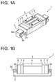
FIGS. 1A and 1B are an external view and a side view of a linear guide apparatus according to a first embodiment. -
FIGS. 2A and 2B are a front view and a rear view of an end cap according to the first embodiment. -
FIGS. 3A, 3B and 3C are a front view, a side view and a rear view of a lubricant container according to the first embodiment. -
FIGS. 4A and 4B are a rear view and a side view of the lubricant container according to the first embodiment, a dotted line representing an internal structure of the lubricant container inFIG. 4B . -
FIGS. 5A, 5B, 5C and 5D are a side view and a front view of one cover of the lubricant container, and a side view and a front view of another cover thereof according to the first embodiment. -
FIGS. 6A and 6B are a sectional view taken along theline 6A-6A ofFIG. 2A and a partially enlarged view ofFIG. 6A , illustrating how the lubricant container is attached to the end cap according to the first embodiment. -
FIGS. 7A and 7B are a side view of a slider body and a view depicting an end surface of the slider body according to the first embodiment. -
FIG. 8 is a view illustrating a side seal according to the first embodiment. -
FIGS. 9A - 9C are views illustrating how the slider according to the first embodiment is assembled, and depicting an end surface and a side surface of the slider. -
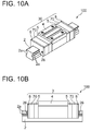
FIGS. 10A and 10B are an external view and a side view of a linear guide apparatus according to a second embodiment. -
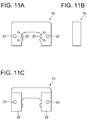
FIGS. 11A, 11B and 11C are a front view, a side view and a rear view of the lubricant container according to the second embodiment. -
FIGS. 12A and 12B are a rear side and a side view of the lubricant container according to the second embodiment, a dotted line inFIG. 12B depicting an internal structure of the lubricant container. -
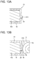
FIGS. 13A and 13B are a view illustrating a lubricating member retained in the lubricant container according to the second embodiment, and a sectional view, corresponding toFIG. 6A in the first embodiment, depicting how the lubricant container is attached to the end cap. -
FIGS. 14A - 14C are views illustrating how the slider according to the second embodiment is assembled, and depicting end surfaces and side surfaces of the slider. - A linear guide apparatus including a lubricant supply device for the linear guide apparatus according to each of embodiments of the present invention will hereinafter be described based on the accompanying drawings. In the present specification, in a state where a guide rail of the linear guide apparatus is horizontalized, a direction intersecting the horizontal direction at a right angle is set as a widthwise direction with respect to a longitudinal direction of the guide rail, and a direction intersecting perpendicularly both of the longitudinal direction and the widthwise direction is set as a vertical direction. An up-sided surface, a low-sided surface and widthwise surfaces each extending in the longitudinal direction of the guide rail are defined as an upper surface, a lower surface and side surfaces, respectively; and end-sided surfaces in the longitudinal direction are defined as end surfaces.
- The discussion will begin with an overview of configuration of the linear guide apparatus including the lubricant supply device for the linear guide apparatus according to the first embodiment with reference to
FIG. 1 . Alinear guide apparatus 1 according to the first embodiment illustrated inFIG. 1 is suitable for a numerical control (NC) machine tool, an NC measuring machine and other equivalent machines, the linear guide apparatus being configured to include aguide rail 2 and aslider 3 movable along theguide rail 2. Theguide rail 2 is composed of a member taking substantially a square shape, and includes rollinggrooves 2a formed by twos in both of side surface so as to extend in the longitudinal direction. Theslider 3 is configured to include aslider body 4, and couples ofend caps 5,lubricant containers 7 andside seals 8, these couples components being fitted to both of ends of theslider body 4 in the longitudinal direction, i.e., in a bilateral direction inFIG. 1B in this sequence from theslider body 4. - The
slider body 4 is, as depicted inFIG. 1A and7 , composed of a metallic member extending in the longitudinal direction of theguide rail 2 and taking substantially a U-shape in section, theslider body 4 being fitted to theguide rail 2 so as to slidably bridge over the guide rail 2 (so as to slidably stride over the guide rail 2). As illustrated inFIG. 7B , rollinggrooves 4a extending in the longitudinal direction are provided by twos in a face-to-face relation with the rollinggrooves 2a of theguide rail 2, these rollinggrooves 4a being formed in portions, opposite to both of the side surfaces of theguide rail 2, of theslider body 4, i.e., in both of inside surface of leg portions of theslider body 4. Rolling paths for unillustrated rolling elements are configured by the rollinggrooves 4a of theslider body 4 and the rollinggrooves 2a of theguide rail 2. Note that a plurality of balls serving as the rolling elements is loaded into the rolling paths. As depicted inFIG. 7B , returnpaths 4b each taking a circular shape in section are formed by twos in the leg portions on both sides of theslider body 4 so as to penetrate in the longitudinal direction of theslider body 4, i.e., in the perpendicular direction as viewed on the sheet surface inFIG. 7B . Screw holes 11, 12 are formed by twos in both of the end surfaces of theslider body 4. - The
end cap 5 is a resinous member and takes substantially the U-shape as depicted inFIG. 2 . As illustrated inFIG. 2A ,direction change paths 5a each taking a circular shape in section are formed by twos in leg portions on both sides of a front surface of theend cap 5, i.e., the surface directed to theslider body 4. Thedirection change path 5a serves to communicate the rolling path and thereturn path 4b with each other, and takes a semicircular shape as depicted inFIG. 6A . Theend cap 5 includes circular through-holes slider body 4. Note that theend cap 5 may be formed from a metal without being limited to the resin. - With the configuration described above, the plurality of rolling elements rolls within the rolling paths, and the
slider 3 is thereby enabled to perform a linear motion along on theguide rail 2. Note that the plurality of rolling elements can circulate along the rolling path, thedirection change paths 5a and thereturn path 4b. Theside seal 8 is, as depicted inFIG. 8 , a resinous or rubber plate member taking substantially the U-shape in section so as to fit to both of the side surfaces and the upper surface of theguide rail 2 so as to bridge over the guide rail 2 (so as to slidably stride over the guide rail 2). Theside seal 8 taking such a shape enables, upon causing theslider 3 to perform the linear motion on theguide rail 2, elimination of foreign matters instanced by dusts, motes, contaminants and other equivalent matters, which are adhered onto both of the side surfaces and the upper surface of theguide rail 2. Note that theside seal 8 includes circular through-holes 9 formed in positions having the face-to-face relation with the screw holes 12 of theslider body 4. - Described next is a most characteristic configuration of the lubricant supply device of the linear guide apparatus according to the first embodiment. The lubricant supply device for the
linear guide apparatus 1 according to the first embodiment supplies the lubricant into theslider 3, and is configured to include theend caps 5, thelubricant containers 7 andlubricating members 15 that will be described later on. Thedirection change path 5a of theend cap 5 is formed with the circular through-hole 16 extending in the longitudinal direction of theslider 3, i.e., the bilateral direction inFIG. 6A . This configuration entails referring toFIG. 2A as well. - The
lubricant container 7 serves to retain the lubricatingmember 15 and is a thick resinous plate member having substantially the same external shape as the external shape of theend cap 5, i.e., substantially the U-shape in section as illustrated inFIG. 3 . Recessedportions 18 each producing an air space taking substantially a cubic shape are, as depicted inFIG. 4A , provided respectively in positions, which face the four through-holes 16 of theend caps 5, of rear surfaces of thelubricant containers 7, i.e., the outside surfaces of theslider 3 in the longitudinal direction. As illustrated inFIG. 3A ,cylindrical portions 19 are integrally formed in positions of the front surfaces of thelubricant containers 7, these positions facing the four through-holes 16 of theend cap 5 as well as facing the four recessedportions 18. Eachcylindrical portion 19 takes a circularly cylindrical shape suited to fitting into the through-hole 16 of the direction changepath 5a of theend cap 5, the cylindrical shape extending, as illustrated inFIG. 6A , inwardly in the longitudinal direction of theslider 3, i.e., in the right direction inFIG. 6A . A hollowed portion defined as a circular aperture within thecylindrical portion 19 penetrates a bottom surface of the opposite recessedportion 18. Note that thelubricant container 7 includes circular through-holes 20 respectively formed in positions having the face-to-face relation with the twoscrew holes 12 of theslider body 4. - Each recessed
portion 18 of thelubricant container 7 retains, as illustrated inFIG. 6A , the lubricatingmember 15 composed of a porous molding impregnated with the lubricant. The lubricatingmember 15 takes substantially a cubic shape fitted into the recessedportion 18, and is integrally formed with a cylindrical protrudedportion 21 fitted into the circular aperture of thecylindrical portion 19. In other words, the air space defined by the recessedportion 18 and thecylindrical portion 19 of thelubricant container 7 is filled with the lubricatingmember 15 without any gap. The recessedportion 18 retaining the lubricatingmember 15 is, as depicted inFIG. 3C , hermetically sealed by its being attached with acover 22 from the rear surface side of thelubricant container 7. Thecover 22 is, as illustrated inFIG. 5 , composed of the plate member made from the same resin as thelubricant container 7, and takes a rectangular shape for hermetically sealing the two recessedportions 18 of thelubricant container 7 at one time. Note that thecover 22 is formed with a circular through-hole 23 in a position opposite to the through-hole 20 of thelubricant container 7. - With the configuration described above, as illustrated in
FIG. 6A , when attaching thelubricant container 7 retaining the lubricatingmember 15 to theend cap 5, thecylindrical portion 19 of thelubricant container 7 can be fitted into the through-hole 16 of the direction changepath 5a of theend cap 5. Thecylindrical portion 19 of thelubricant container 7 and the protrudedportion 21 of the lubricatingmember 15 can be exposed into the direction changepath 5a. Herein, in the longitudinal direction of theslider body 4, i.e., in the bilateral direction inFIG. 6 , a length of thecylindrical portion 19 of thelubricant container 7 and a length of theprojection 21 serving as the protrudedportion 21 of the lubricatingmember 15, are designed not to produce a stepped portion among thecylindrical portion 19, the protrudedportion 21 and the rolling groove. A front end surface of thecylindrical portion 19 of thelubricant container 7 and a front end surface of the protrudedportion 21 of the lubricatingmember 15 are, as depicted inFIG. 6B , each worked in a curved surface shape matching with the rollinggroove 2a of the direction changepath 5a of theend cap 5. - Procedures of how the
slider 3 according to the first embodiment is assembled will be described with reference toFIG. 9 . Note that thelubricant container 7 is hermetically sealed beforehand by inserting the lubricatingmember 15 into each recessedportion 18 and attaching thecover 22 from the rear surface side. - Procedure 1: The end caps 5 are, as illustrated in
FIG. 9A , disposed at both of end portions of theslider body 4 in the longitudinal direction, with the surfaces formed with thedirection change paths 5a, i.e., the front faces being directed toward theslider body 4.Screws 24 are fixed into screw holes 11 of theslider body 4 through the through-holes 13 of theend caps 5. The through-holes 13 and the screw holes 11 are unillustrated inFIG. 9 . With thisprocedure 1, the attachment of theend caps 5 to theslider body 4 is attained. - Procedure 2: As depicted in
FIG. 9B , on eachend cap 5 thelubricant container 7 is attached from the outside of theslider body 4 in the longitudinal direction, with the surface formed with thecylindrical portions 19, i.e., the front face being directed toward theend cap 5. Thecylindrical portions 19 are unillustrated inFIG. 9 . At this time, thecylindrical portions 19 of thelubricant container 7 are inserted respectively into the through-holes 16 of theend cap 5. Positioning of thelubricant container 7 with respect to theend cap 5 is thereby attained. - Procedure 3: As depicted in
FIG. 9C , on eachlubricant container 7 theside seal 8 is disposed from the outside of theslider body 4 in the longitudinal direction.Screws 26 are fixed into the screw holes 12 of theslider body 4 via the through-holes 9 of theside seal 8, the through-holes 23 of thecover 22 for thelubricant container 7, the through-holes 20 of thelubricant container 7, and through-holes 14 of theend cap 5 in this sequence. The through-holes FIG. 7 . The attachment of thelubricant containers 7 and the side seals 8 to theslider body 4 is thereby attained. - The
slider 3 can be easily assembled through the assembly procedures described above. Especially in theprocedure 2, thecylindrical portions 19 of thelubricant container 7 are inserted respectively into the four through-holes 16 of theend cap 5 in the manner described above, whereby thelubricant container 7 can be positioned with respect to theend cap 5. Hence, in theprocedure 3, thelubricant container 7 can be easily fixed together with theside seal 8 to theslider body 4 by use of the common screws 26. The configuration being such that thelubricating members 15 are held respectively in the four recessedportions 18 of thelubricant container 7 as described above, the fourlubricating members 15 can be treated at one time by thelubricant container 7. This configuration therefore facilitates the assembly of theslider 3 and also maintenance of theslider 3. Thelubricating members 15 can be individually treated, and hence theslider 3 can be uniformly lubricated throughout. - In the
slider body 4 being assembled based on the assembly procedures described above, the front end of thecylindrical portion 19 of thelubricant container 7 and the front end of the protrudedportion 21 of the lubricatingmember 15 are exposed from the through-hole 16 into the direction changepath 5a of theend cap 5, and form a curved surface along the rolling groove of the direction changepath 5a within the through-hole 16. More specifically, the front end surface of thecylindrical portion 19 of thelubricant container 7 and the front end surface of the protrudedportion 21 of the lubricatingmember 15 configure the single curved surface together with the rolling groove of the direction changepath 5a. This configuration enables, when causing theslider 3 to perform the linear motion on theguide rail 2, the lubrication into theslider 3 by applying the lubricant over the front end surface of the protrudedportion 21 of the lubricatingmember 15 upon a contact between the rolling elements rolling along the direction changepath 5a and the front end surface of the protrudedportion 21. - As described above, the front end of the
cylindrical portion 19 of thelubricant container 7 and the front end of the protrudedportion 21 of the lubricatingmember 15 form the curved surface along the rolling groove of the direction changepath 5a, thereby enabling the rolling elements to smoothly roll within the direction changepath 5a. It does not therefore happen that the rolling elements bump against the lubricatingmember 15, and fragments of the broken lubricatingmember 15 enter as foreign matters between the direction changepath 5a and the rolling elements as seen in the prior arts. A possibility does not arise of causing a zigzag run of the rolling element upon a bump against a stepped portion produced between the direction changepath 5a and the lubricatingmember 15 as seen in the prior arts. It is therefore feasible to prevent the rolling elements and the direction changepath 5a from being damaged, also prevent a failure and an operational defect of theslider 3. - A detailed discussion will focus on different components, from those of the first embodiment, of a
linear guide apparatus 100 including a lubricant supply device for the linear guide apparatus according to a second embodiment illustrated inFIG. 10 , while omitting the repetitive explanations of the same components marked with the same numerals and symbols as those of the first embodiment. The lubricant supply device for the linear guide apparatus according to the second embodiment is configured to include theend caps 5,lubricant containers 70 andlubricating members 150. - As illustrated in
FIGS. 11A and12A , each of thelubricant containers 70 according to the second embodiment includes, in place of thecylindrical portions 19 of thelubricant containers 7 in the first embodiment,circular apertures 25 each having the same diameter as the diameter of the through-hole 16, theapertures 25 being formed in positions in the face-to-face relation with the four recessedportions 18 and with the four through-holes 16 of theend cap 5. As depicted inFIG. 13A , the lubricatingmember 150 retained in the recessedportion 18 of thelubricant container 70 takes substantially the cubic shape suited to fitting in the recessedportion 18, and is integrally formed with a protrudedportion 210 extending inward in the longitudinal direction of aslider 30, i.e., in the right direction inFIG. 13A , and protruding outwardly from thecircular aperture 25 of thelubricant container 70. The protrudedportion 210 takes, as illustrated inFIG. 13B , a circular column shape suited to fitting in thecircular aperture 25 of thelubricant container 70 and in the through-hole 16 of theend cap 5. - The configuration described above enables, as depicted in
FIG. 13B , the protrudedportion 210 of the lubricatingmember 150 to be fitted in the through-hole 16 of the direction changepath 5a of theend cap 5. The protrudedportion 210 of the lubricatingmember 150 can be exposed into the direction changepath 5a. Herein, in the longitudinal direction of theslider body 4, i.e., in the bilateral direction inFIG. 13B , a length of the protrudedportion 210 of the lubricatingmember 150 is designed not to produce a stepped portion among the protrudedportion 210 and the rolling groove of the direction changepath 5a of theend cap 5. A front end surface of the protrudedportion 210 of the lubricatingmember 150 is, as depicted inFIG. 13B , worked in a curved surface shape matching with the rolling groove of the direction changepath 5a of theend cap 5. - Procedures of how the
slider 30 according to the second embodiment is assembled will be described with reference toFIG. 14 . Note that thelubricant container 70 is hermetically sealed beforehand by inserting the lubricatingmember 150 into each recessedportion 18 and attaching thecover 22 from the rear surface side. - Procedure 1: The same as the
procedure 1 of the assembly procedures of theslider 3 according to the first embodiment. Theprocedure 1 entails referring tofig. 14A - Procedure 2: As illustrated in
FIG. 14B , thelubricant container 70 is attached to eachend cap 5 from outwardly of theslider body 4 in the longitudinal direction, with the surface formed with thecircular aperture 25, i.e., the front face being directed toward theend cap 5. Thecircular aperture 25 is unillustrated inFIG. 12 . Hereat, the protrudedportion 210 of the lubricatingmember 150 is inserted into each through-hole 16 of theend cap 5. The positioning of thelubricant container 70 with respect to theend cap 5 is thereby attained. - Procedure 3: The same as the
procedure 3 of the assembly procedures of theslider 3 according to the first embodiment. Theprocedure 3 entails referring tofig. 14C . - The
slider 30 can be easily assembled through the assembly procedures described above. Especially in theprocedure 2, the protrudedportions 210 of thelubricating members 150 are inserted into the four through-holes 16 of theend caps 5, whereby thelubricant containers 70 can be positioned with respect to theend caps 5. Therefore, the same effects as those in the first embodiment can be exhibited. - In the
slider 30 assembled based on the assembly procedures, the front end of the protrudedportion 210 of the lubricatingmember 150 is, as depicted inFIG. 13B , exposed from within the through-hole 16 into the direction changepath 5a of theend cap 5, and a curved surface is formed along the rolling groove of the direction changepath 5a within the through-hole 16. More specifically, the front end surface of the protrudedportion 210 of the lubricatingmember 150 configures a single curved surface together with the rolling groove of the direction changepath 5a. With this configuration, the same effects as those in the first embodiment can be exhibited. - In particular, the
lubricant container 70 according to the second embodiment does not include thecylindrical portion 19 of thelubricant container 7 according to the first embodiment, and hence there is no possibility of causing a slight backlash between the front end of thecylindrical portion 19 and the direction changepath 5a due to working accuracy of thecylindrical portion 19. The rolling elements are thereby enabled to smoothly roll within the direction changepath 5a. It is therefore feasible to effectively prevent the rolling elements and the direction changepath 5a from being damaged, and also effectively prevent the failure and the operational defect of theslider 3. - In the respective embodiments, the through-
hole 16 of the direction changepath 5a of theend cap 5 takes the circular shape, as the shapes corresponding to this circular shape, thecylindrical portion 19 of thelubricant container 7 takes the circularly cylindrical shape, and the protrudedportion 21 of the lubricatingmember 15 takes the circular column shape in the first embodiment. In the second embodiment, thelubricant container 70 is provided with thecircular apertures 25, and the protrudedportion 210 of the lubricatingmember 150 takes the circular column shape. Without being limited to these shapes, however, the through-hole 16 of the direction changepath 5a takes, e.g., a rectangular shape, and the respective portions of thelubricant containers lubricating members - In each of the respective embodiments, the
lubricant containers lubricating members holes 16 of thedirection change paths 5a of theend cap 5. Without being limited to this configuration, however, two lubricating members each provided with two protrudedportions lubricant container covers 22 are composed of resins but may be composed of metals without being limited to the resins. - The configuration in each of the embodiments is that the lubricating
member portions 18 of thelubricant container portions 18 of thelubricant containers portion 18 of thelubricant container 7 and by thecylindrical portion 19. Further, the second embodiment may adopt a configuration that the lubricant fills an air space defined by the recessedportion 18 of thelubricant container 70, thecircular aperture 25 and the through-hole 16 of the direction changepath 5a of theend cap 5. - In the respective embodiments, it is preferable to use synthetic resins having high chemical resistance, instanced concretely by polyethlene (PE), polypropylene (PP), polyamide (PA) and polyacetal (POM) as materials of the
lubricant containers end cap 5 involves preferably using POM having elasticity to facilitate the fitting to theslider body 4. Therefore, a material of thelubricant container end cap 5 and to enable absorption of minute vibrations intermittently generated when theslider guide rail 2 and theguide rail 2. - In the respective embodiments, a material of the lubricating
member member lubricant container member lubricant container path 5a of theend cap 5 and the rolling elements when theslider guide rail 2, in which case also the insulation can be attained by lubricatingmember lubricant container - In the first embodiment, as illustrated in
FIG. 6B , thecylindrical portion 19 of thelubricant container 7 exposed to the direction changepath 5a of theend cap 5 and the protrudedportion 21 of the lubricatingmember 15, are flush with the rolling groove of the direction changepath 5a. Consequently, it does not happen that the protrudedportion 21 of the lubricatingmember 15 is damaged upon the bump against the rolling elements. As described above, POM has the elasticity, and hence, when the lubricatingmember 15 is composed of POM, such an effect is exhibited at the maximum, whereby the lubricatingmember 15 can be well protected. Note that the same is applied to the protrudedportion 210 of the lubricatingmember 150 in the second embodiment described above. In the case of the configuration that thecylindrical portion 19 of thelubricant container 7 is, as illustrated inFIG. 6B , fitted to the protrudedportion 21 of the lubricatingmember 15, it is preferable that the fitting of protrudedportion 21 to thecylindrical portion 19 is facilitated by using PE as a soft material of the lubricatingmember 15. Incidentally, it is more preferable that PE is compounded with PP to provide rigidity to PE. - Other materials of the lubricating
member member - The lubricant supply devices for the linear guide apparatus are provided at both of the end portions of the
slider body 4, and, however, it is also an available configuration to provide the lubricant supply device for the linear guide apparatus at only one end portion of theslider body 4. The respective embodiments have exemplified thelinear guide apparatuses
Claims (9)
- A lubricant supply device for a linear guide apparatus, comprising:an end cap disposed at an end portion of a slider in a longitudinal direction, and having a direction change path for changing over a rolling direction of rolling elements within the slider; anda container retaining lubricant and disposed adjacent to the end cap,the end cap being formed with a through-hole extending toward the container from the direction change path,the container being formed with an aperture communicating with the through-hole of the end cap,the lubricant being supplied into the direction change path via the through-hole of the end cap.
- The lubricant supply device for the linear guide apparatus according to claim 1, wherein the container retains a lubricating member having a protruded portion composed of porous molding impregnated with the lubricant,
the protruded portion of the lubricating member protrudes from the aperture of the container, inserted into the through-hole of the end cap and is exposed into the direction change path, and
a front end of the protruded portion of the lubricating member forms a curved surface along rolling groove of the direction change path. - The lubricant supply device for the linear guide apparatus according to claim 2, wherein the container includes a cylindrical portion in position of the aperture,
the protruded portion of the lubricating member, which protrude from the aperture of the container, is fitted in a hollowed portion within the cylindrical portion,
the cylindrical portion of the container is fitted in the through-hole of the end cap, and the protruded portion of the lubricating member and the cylindrical portion of the container are exposed into the direction change path of the end cap, and
the front end of the protruded portion of the lubricating member and the front end of the cylindrical portions form the curved surfaces along the rolling groove of the direction change path of the end cap. - The lubricant supply device for the linear guide apparatus according to claim 2, wherein the protruded portion of the lubricating member, which protrudes from the aperture of the container, is fitted in the through-hole of the end cap.
- The lubricant supply device for the linear guide apparatus according to claim 1, wherein the container has a recessed portion to retain the lubricant, and a cover to cover the recessed portion, and
the aperture is formed in a bottom surface of the recessed portion. - The lubricant supply device for the linear guide apparatus according to any one of claims 2 through 4, wherein the container has a recessed portion to retain the lubricant, and a cover to cover the recessed portion, and
the aperture is formed in a bottom surface of the recessed portion. - The lubricant supply device for the linear guide apparatus according to claim 5 or 6, wherein the end cap has a plurality of direction change path,
the plurality of direction change path each is formed with the through-hole, and
the container includes the same number of recessed portions as a number of through-holes of the end cap. - A linear guide apparatus including the lubricant supply device for the linear guide apparatus according to any one of claims 1 through 7.
- The linear guide apparatus according to claim 8, wherein the slider has a side seal disposed adjacent to the container,
the side seal, the container and the end cap are respectively formed with through-holes in a face-to-face relation with a screw hole formed in an end portion of a slider body in a longitudinal direction thereof, and
a screw is fitted in the screw hole of the slider body via the through-holes of the side seal, the container and the end cap in this sequence.
Applications Claiming Priority (3)
| Application Number | Priority Date | Filing Date | Title |
|---|---|---|---|
| JP2013066529 | 2013-03-27 | ||
| JP2014023927 | 2014-02-11 | ||
| PCT/JP2014/055112 WO2014156473A1 (en) | 2013-03-27 | 2014-02-28 | Oil supply device for linear guide device, and linear guide device |
Publications (2)
| Publication Number | Publication Date |
|---|---|
| EP2980428A1 true EP2980428A1 (en) | 2016-02-03 |
| EP2980428A4 EP2980428A4 (en) | 2016-11-02 |
Family
ID=51623467
Family Applications (1)
| Application Number | Title | Priority Date | Filing Date |
|---|---|---|---|
| EP14776389.0A Withdrawn EP2980428A4 (en) | 2013-03-27 | 2014-02-28 | Oil supply device for linear guide device, and linear guide device |
Country Status (5)
| Country | Link |
|---|---|
| US (1) | US10294993B2 (en) |
| EP (1) | EP2980428A4 (en) |
| CN (1) | CN104246250A (en) |
| TW (1) | TW201447129A (en) |
| WO (1) | WO2014156473A1 (en) |
Families Citing this family (5)
| Publication number | Priority date | Publication date | Assignee | Title |
|---|---|---|---|---|
| WO2015002201A1 (en) * | 2013-07-04 | 2015-01-08 | 日本精工株式会社 | Oil supply device for linear guide device, and linear guide device |
| CN107110207B (en) * | 2015-02-25 | 2019-07-02 | 日本精工株式会社 | Oil supply devices and rolling bearing guides for rolling bearing guides |
| DE202015102452U1 (en) * | 2015-05-13 | 2016-08-17 | Robert Bosch Gmbh | Carriage with lubrication channel and plastic film |
| JP6668652B2 (en) | 2015-09-18 | 2020-03-18 | 日本精工株式会社 | Linear motion guide device, end cap for linear motion guide device |
| CN107477346B (en) * | 2017-09-30 | 2020-11-03 | 京东方科技集团股份有限公司 | Rail oil filling tool |
Family Cites Families (23)
| Publication number | Priority date | Publication date | Assignee | Title |
|---|---|---|---|---|
| JP2543304Y2 (en) * | 1990-05-18 | 1997-08-06 | 日本精工株式会社 | Oil leakage prevention structure of linear guide device |
| JP2696446B2 (en) * | 1991-09-10 | 1998-01-14 | 株式会社ユニシアジェックス | In-cylinder direct injection type injection valve assist air supply device |
| JPH0571443U (en) | 1992-03-02 | 1993-09-28 | 光洋精工株式会社 | Direct acting guide device |
| DE4331013C2 (en) * | 1993-08-12 | 1998-04-09 | Schaeffler Waelzlager Ohg | Scraper unit for a bearing element |
| US6125968A (en) * | 1996-12-09 | 2000-10-03 | Thk Co., Ltd. | Lubricating oil supply system for a rolling guide apparatus |
| JP4070265B2 (en) * | 1997-07-01 | 2008-04-02 | Thk株式会社 | Linear guide device |
| JP3935247B2 (en) * | 1997-09-18 | 2007-06-20 | 日本トムソン株式会社 | Linear motion guidance unit |
| US6401867B1 (en) * | 1998-04-16 | 2002-06-11 | Thk Co., Ltd. | Lubricant supply system |
| DE59910887D1 (en) * | 1998-08-27 | 2004-11-25 | Schneeberger Holding Ag Roggwi | Linear motion guide |
| JP4035241B2 (en) * | 1998-11-13 | 2008-01-16 | 日本トムソン株式会社 | Linear motion guide unit with lubrication device |
| JP4568453B2 (en) * | 2000-05-29 | 2010-10-27 | Thk株式会社 | Exercise guidance device |
| US7473033B2 (en) * | 2006-04-07 | 2009-01-06 | Hiwin Technology Corp. | Ball circulation system for linear guide way |
| JP4965362B2 (en) * | 2007-07-09 | 2012-07-04 | 日本トムソン株式会社 | Roller type linear motion guide unit |
| JP4986775B2 (en) * | 2007-09-05 | 2012-07-25 | 日本トムソン株式会社 | Slider for linear motion rolling guide unit |
| JP5052270B2 (en) * | 2007-09-13 | 2012-10-17 | 日本トムソン株式会社 | Slider for linear motion rolling guide unit |
| JP5164699B2 (en) | 2008-07-04 | 2013-03-21 | 日本トムソン株式会社 | Lubricating member for linear motion rolling guide unit and slider for linear motion rolling guide unit |
| JP2011052700A (en) * | 2009-08-31 | 2011-03-17 | Thk Co Ltd | Lubricating oil supply device and motion guide device using this |
| JP2012052609A (en) * | 2010-09-01 | 2012-03-15 | Nsk Ltd | Linear motion guide device |
| EP2642143A4 (en) * | 2010-11-18 | 2016-03-02 | Nsk Ltd | Direct-acting guide bearing apparatus and seal member used therein |
| JP5726922B2 (en) * | 2013-01-18 | 2015-06-03 | Thk株式会社 | Exercise guidance device |
| JP2015090187A (en) * | 2013-11-06 | 2015-05-11 | 日本精工株式会社 | Rolling bearing guide device |
| DE102014210171A1 (en) * | 2014-05-28 | 2015-12-17 | Robert Bosch Gmbh | Carriage with mounting hole, which is part of a lubricant flow path |
| US10107336B2 (en) * | 2015-03-31 | 2018-10-23 | Nsk Ltd. | Oil supply device and linear motion guide device |
-
2014
- 2014-02-28 US US14/780,547 patent/US10294993B2/en active Active
- 2014-02-28 WO PCT/JP2014/055112 patent/WO2014156473A1/en not_active Ceased
- 2014-02-28 EP EP14776389.0A patent/EP2980428A4/en not_active Withdrawn
- 2014-02-28 CN CN201480000840.6A patent/CN104246250A/en active Pending
- 2014-03-26 TW TW103111217A patent/TW201447129A/en unknown
Also Published As
| Publication number | Publication date |
|---|---|
| EP2980428A4 (en) | 2016-11-02 |
| CN104246250A (en) | 2014-12-24 |
| US10294993B2 (en) | 2019-05-21 |
| TW201447129A (en) | 2014-12-16 |
| WO2014156473A1 (en) | 2014-10-02 |
| US20160061261A1 (en) | 2016-03-03 |
Similar Documents
| Publication | Publication Date | Title |
|---|---|---|
| US10294993B2 (en) | Lubricant supply device for linear guide apparatus, and linear guide apparatus | |
| JP5600468B2 (en) | Motion guide device and screw device | |
| CN102713318B (en) | Linear motion guide device | |
| JP4489557B2 (en) | Ball screw lubrication seal device | |
| US10774872B2 (en) | Linear guide | |
| CN107429739B (en) | Oil supply and linear motion guide | |
| JP2015224783A (en) | Direct-acting rolling guide unit | |
| EP2913545B1 (en) | Linear motion guide device | |
| JP6390616B2 (en) | Oil supply device for linear guide device, linear guide device | |
| US9803688B2 (en) | Rolling bearing guide apparatus | |
| KR102324533B1 (en) | Ball Screw | |
| JP6574585B2 (en) | Linear motion guidance unit | |
| JP2015187491A (en) | Oil supply device for linear guide device, linear guide device | |
| JP5187185B2 (en) | Rolling support device | |
| JP5928337B2 (en) | How to use the linear guide device | |
| JPWO2008120496A1 (en) | Rolling device seal member, rolling device | |
| JP2017141950A (en) | Oil supply device for rolling bearing guide device, rolling bearing guide device | |
| DE102020204244A1 (en) | Electric machine | |
| CN105814328A (en) | Roller bearing guide device | |
| JP4116038B2 (en) | Linear motion guide bearing device | |
| JP2016156467A (en) | Oil supply device for rolling bearing guide device and rolling bearing guide device | |
| WO2016136778A1 (en) | Oil supply device for rolling bearing guide device, and rolling bearing guide device | |
| JP2016211736A (en) | Rolling bearing guide device | |
| JP2007211823A (en) | Linear motion guide bearing device | |
| JP2010185565A (en) | Lubricant supply member for linear guide device and linear guide device including the same |
Legal Events
| Date | Code | Title | Description |
|---|---|---|---|
| PUAI | Public reference made under article 153(3) epc to a published international application that has entered the european phase |
Free format text: ORIGINAL CODE: 0009012 |
|
| 17P | Request for examination filed |
Effective date: 20150924 |
|
| AK | Designated contracting states |
Kind code of ref document: A1 Designated state(s): AL AT BE BG CH CY CZ DE DK EE ES FI FR GB GR HR HU IE IS IT LI LT LU LV MC MK MT NL NO PL PT RO RS SE SI SK SM TR |
|
| AX | Request for extension of the european patent |
Extension state: BA ME |
|
| DAX | Request for extension of the european patent (deleted) | ||
| A4 | Supplementary search report drawn up and despatched |
Effective date: 20161006 |
|
| RIC1 | Information provided on ipc code assigned before grant |
Ipc: F16C 29/06 20060101AFI20160929BHEP Ipc: F16C 33/76 20060101ALI20160929BHEP Ipc: F16N 7/12 20060101ALI20160929BHEP |
|
| STAA | Information on the status of an ep patent application or granted ep patent |
Free format text: STATUS: REQUEST FOR EXAMINATION WAS MADE |
|
| STAA | Information on the status of an ep patent application or granted ep patent |
Free format text: STATUS: THE APPLICATION IS DEEMED TO BE WITHDRAWN |
|
| 18D | Application deemed to be withdrawn |
Effective date: 20170505 |