EP2980392A2 - System und verfahren für vermindertes spaltenvolumen einer kolbenzylinderanordnung - Google Patents
System und verfahren für vermindertes spaltenvolumen einer kolbenzylinderanordnung Download PDFInfo
- Publication number
- EP2980392A2 EP2980392A2 EP15178534.2A EP15178534A EP2980392A2 EP 2980392 A2 EP2980392 A2 EP 2980392A2 EP 15178534 A EP15178534 A EP 15178534A EP 2980392 A2 EP2980392 A2 EP 2980392A2
- Authority
- EP
- European Patent Office
- Prior art keywords
- seal
- cylinder head
- flange
- inner seal
- cylinder
- Prior art date
- Legal status (The legal status is an assumption and is not a legal conclusion. Google has not performed a legal analysis and makes no representation as to the accuracy of the status listed.)
- Withdrawn
Links
- 238000000034 method Methods 0.000 title claims description 18
- 238000002485 combustion reaction Methods 0.000 claims abstract description 105
- 238000012546 transfer Methods 0.000 claims abstract description 23
- 238000005219 brazing Methods 0.000 claims description 81
- 239000000463 material Substances 0.000 claims description 38
- 239000000567 combustion gas Substances 0.000 claims description 11
- 229910000831 Steel Inorganic materials 0.000 claims description 5
- 239000010959 steel Substances 0.000 claims description 5
- VYZAMTAEIAYCRO-UHFFFAOYSA-N Chromium Chemical compound [Cr] VYZAMTAEIAYCRO-UHFFFAOYSA-N 0.000 claims description 4
- 229910052804 chromium Inorganic materials 0.000 claims description 4
- 239000011651 chromium Substances 0.000 claims description 4
- 229910052710 silicon Inorganic materials 0.000 claims description 4
- 239000010703 silicon Substances 0.000 claims description 4
- 239000000919 ceramic Substances 0.000 claims description 2
- 239000000446 fuel Substances 0.000 description 26
- 229910045601 alloy Inorganic materials 0.000 description 19
- 239000000956 alloy Substances 0.000 description 19
- PXHVJJICTQNCMI-UHFFFAOYSA-N Nickel Chemical compound [Ni] PXHVJJICTQNCMI-UHFFFAOYSA-N 0.000 description 14
- 230000008018 melting Effects 0.000 description 9
- 238000002844 melting Methods 0.000 description 9
- 238000005452 bending Methods 0.000 description 7
- 239000010949 copper Substances 0.000 description 7
- 239000000047 product Substances 0.000 description 7
- KDLHZDBZIXYQEI-UHFFFAOYSA-N Palladium Chemical compound [Pd] KDLHZDBZIXYQEI-UHFFFAOYSA-N 0.000 description 6
- 239000007789 gas Substances 0.000 description 6
- 230000001965 increasing effect Effects 0.000 description 6
- 229910052759 nickel Inorganic materials 0.000 description 6
- 239000007800 oxidant agent Substances 0.000 description 6
- 230000001590 oxidative effect Effects 0.000 description 6
- RYGMFSIKBFXOCR-UHFFFAOYSA-N Copper Chemical compound [Cu] RYGMFSIKBFXOCR-UHFFFAOYSA-N 0.000 description 5
- BQCADISMDOOEFD-UHFFFAOYSA-N Silver Chemical compound [Ag] BQCADISMDOOEFD-UHFFFAOYSA-N 0.000 description 5
- 229910052802 copper Inorganic materials 0.000 description 5
- 229910052709 silver Inorganic materials 0.000 description 5
- 239000004332 silver Substances 0.000 description 5
- 238000013461 design Methods 0.000 description 4
- PCHJSUWPFVWCPO-UHFFFAOYSA-N gold Chemical compound [Au] PCHJSUWPFVWCPO-UHFFFAOYSA-N 0.000 description 4
- 239000010931 gold Substances 0.000 description 4
- 229910052737 gold Inorganic materials 0.000 description 4
- 239000000203 mixture Substances 0.000 description 4
- 239000012812 sealant material Substances 0.000 description 4
- XEEYBQQBJWHFJM-UHFFFAOYSA-N Iron Chemical compound [Fe] XEEYBQQBJWHFJM-UHFFFAOYSA-N 0.000 description 3
- QVGXLLKOCUKJST-UHFFFAOYSA-N atomic oxygen Chemical compound [O] QVGXLLKOCUKJST-UHFFFAOYSA-N 0.000 description 3
- 238000005260 corrosion Methods 0.000 description 3
- 230000007797 corrosion Effects 0.000 description 3
- -1 etc.) Substances 0.000 description 3
- MWUXSHHQAYIFBG-UHFFFAOYSA-N nitrogen oxide Inorganic materials O=[N] MWUXSHHQAYIFBG-UHFFFAOYSA-N 0.000 description 3
- 239000001301 oxygen Substances 0.000 description 3
- 229910052760 oxygen Inorganic materials 0.000 description 3
- 229910052763 palladium Inorganic materials 0.000 description 3
- 239000000565 sealant Substances 0.000 description 3
- ATUOYWHBWRKTHZ-UHFFFAOYSA-N Propane Chemical compound CCC ATUOYWHBWRKTHZ-UHFFFAOYSA-N 0.000 description 2
- 229910052782 aluminium Inorganic materials 0.000 description 2
- XAGFODPZIPBFFR-UHFFFAOYSA-N aluminium Chemical compound [Al] XAGFODPZIPBFFR-UHFFFAOYSA-N 0.000 description 2
- 230000008901 benefit Effects 0.000 description 2
- BERDEBHAJNAUOM-UHFFFAOYSA-N copper(I) oxide Inorganic materials [Cu]O[Cu] BERDEBHAJNAUOM-UHFFFAOYSA-N 0.000 description 2
- KRFJLUBVMFXRPN-UHFFFAOYSA-N cuprous oxide Chemical compound [O-2].[Cu+].[Cu+] KRFJLUBVMFXRPN-UHFFFAOYSA-N 0.000 description 2
- 238000011161 development Methods 0.000 description 2
- 238000010586 diagram Methods 0.000 description 2
- 230000001939 inductive effect Effects 0.000 description 2
- 238000004519 manufacturing process Methods 0.000 description 2
- VNWKTOKETHGBQD-UHFFFAOYSA-N methane Chemical compound C VNWKTOKETHGBQD-UHFFFAOYSA-N 0.000 description 2
- 238000010248 power generation Methods 0.000 description 2
- 238000007789 sealing Methods 0.000 description 2
- 229910000851 Alloy steel Inorganic materials 0.000 description 1
- 229910001369 Brass Inorganic materials 0.000 description 1
- 229910000906 Bronze Inorganic materials 0.000 description 1
- UGFAIRIUMAVXCW-UHFFFAOYSA-N Carbon monoxide Chemical compound [O+]#[C-] UGFAIRIUMAVXCW-UHFFFAOYSA-N 0.000 description 1
- 102100030483 Histatin-1 Human genes 0.000 description 1
- 102100021628 Histatin-3 Human genes 0.000 description 1
- 101001082500 Homo sapiens Histatin-1 Proteins 0.000 description 1
- 101000898505 Homo sapiens Histatin-3 Proteins 0.000 description 1
- OAICVXFJPJFONN-UHFFFAOYSA-N Phosphorus Chemical compound [P] OAICVXFJPJFONN-UHFFFAOYSA-N 0.000 description 1
- 229910001069 Ti alloy Inorganic materials 0.000 description 1
- 230000009471 action Effects 0.000 description 1
- 239000003570 air Substances 0.000 description 1
- 230000015572 biosynthetic process Effects 0.000 description 1
- 239000010951 brass Substances 0.000 description 1
- 239000010974 bronze Substances 0.000 description 1
- 239000006227 byproduct Substances 0.000 description 1
- 229910002091 carbon monoxide Inorganic materials 0.000 description 1
- 229910010293 ceramic material Inorganic materials 0.000 description 1
- 239000003245 coal Substances 0.000 description 1
- KUNSUQLRTQLHQQ-UHFFFAOYSA-N copper tin Chemical compound [Cu].[Sn] KUNSUQLRTQLHQQ-UHFFFAOYSA-N 0.000 description 1
- 238000007599 discharging Methods 0.000 description 1
- 238000009826 distribution Methods 0.000 description 1
- 230000000694 effects Effects 0.000 description 1
- 230000003628 erosive effect Effects 0.000 description 1
- 230000005496 eutectics Effects 0.000 description 1
- 239000002657 fibrous material Substances 0.000 description 1
- 239000000945 filler Substances 0.000 description 1
- 239000000295 fuel oil Substances 0.000 description 1
- 230000006870 function Effects 0.000 description 1
- 239000003502 gasoline Substances 0.000 description 1
- 238000010438 heat treatment Methods 0.000 description 1
- 239000003779 heat-resistant material Substances 0.000 description 1
- 239000001257 hydrogen Substances 0.000 description 1
- 229910052739 hydrogen Inorganic materials 0.000 description 1
- 125000004435 hydrogen atom Chemical class [H]* 0.000 description 1
- 238000003780 insertion Methods 0.000 description 1
- 230000037431 insertion Effects 0.000 description 1
- 229910052742 iron Inorganic materials 0.000 description 1
- 238000005304 joining Methods 0.000 description 1
- 239000003350 kerosene Substances 0.000 description 1
- 239000007788 liquid Substances 0.000 description 1
- 238000012423 maintenance Methods 0.000 description 1
- 239000000155 melt Substances 0.000 description 1
- 239000003345 natural gas Substances 0.000 description 1
- 229910021652 non-ferrous alloy Inorganic materials 0.000 description 1
- 239000003921 oil Substances 0.000 description 1
- 239000003209 petroleum derivative Substances 0.000 description 1
- 229910052698 phosphorus Inorganic materials 0.000 description 1
- 239000011574 phosphorus Substances 0.000 description 1
- 230000008569 process Effects 0.000 description 1
- 239000001294 propane Substances 0.000 description 1
- 230000004044 response Effects 0.000 description 1
- 230000000717 retained effect Effects 0.000 description 1
- 239000010865 sewage Substances 0.000 description 1
- 229910001220 stainless steel Inorganic materials 0.000 description 1
- 239000010935 stainless steel Substances 0.000 description 1
- 229910001256 stainless steel alloy Inorganic materials 0.000 description 1
- 230000002459 sustained effect Effects 0.000 description 1
Images

Classifications
-
- F—MECHANICAL ENGINEERING; LIGHTING; HEATING; WEAPONS; BLASTING
- F02—COMBUSTION ENGINES; HOT-GAS OR COMBUSTION-PRODUCT ENGINE PLANTS
- F02F—CYLINDERS, PISTONS OR CASINGS, FOR COMBUSTION ENGINES; ARRANGEMENTS OF SEALINGS IN COMBUSTION ENGINES
- F02F11/00—Arrangements of sealings in combustion engines
- F02F11/002—Arrangements of sealings in combustion engines involving cylinder heads
-
- F—MECHANICAL ENGINEERING; LIGHTING; HEATING; WEAPONS; BLASTING
- F02—COMBUSTION ENGINES; HOT-GAS OR COMBUSTION-PRODUCT ENGINE PLANTS
- F02F—CYLINDERS, PISTONS OR CASINGS, FOR COMBUSTION ENGINES; ARRANGEMENTS OF SEALINGS IN COMBUSTION ENGINES
- F02F1/00—Cylinders; Cylinder heads
- F02F1/004—Cylinder liners
-
- F—MECHANICAL ENGINEERING; LIGHTING; HEATING; WEAPONS; BLASTING
- F02—COMBUSTION ENGINES; HOT-GAS OR COMBUSTION-PRODUCT ENGINE PLANTS
- F02F—CYLINDERS, PISTONS OR CASINGS, FOR COMBUSTION ENGINES; ARRANGEMENTS OF SEALINGS IN COMBUSTION ENGINES
- F02F1/00—Cylinders; Cylinder heads
- F02F1/02—Cylinders; Cylinder heads having cooling means
- F02F1/10—Cylinders; Cylinder heads having cooling means for liquid cooling
- F02F1/16—Cylinder liners of wet type
-
- F—MECHANICAL ENGINEERING; LIGHTING; HEATING; WEAPONS; BLASTING
- F02—COMBUSTION ENGINES; HOT-GAS OR COMBUSTION-PRODUCT ENGINE PLANTS
- F02F—CYLINDERS, PISTONS OR CASINGS, FOR COMBUSTION ENGINES; ARRANGEMENTS OF SEALINGS IN COMBUSTION ENGINES
- F02F11/00—Arrangements of sealings in combustion engines
- F02F11/005—Arrangements of sealings in combustion engines involving cylinder liners
Definitions
- the subject matter disclosed herein relates generally to reciprocating engines, and, more particularly to reduced a crevice volume of a piston cylinder assembly of a reciprocating engine.
- a reciprocating engine combusts fuel with an oxidant (e.g., air) to generate hot combustion gases, which in turn drive a piston (e.g., a reciprocating piston) within a cylinder liner.
- the hot combustion gases expand and exert a pressure against the piston that linearly moves within the cylinder liner during an expansion stroke (e.g., a down stroke).
- the piston converts the pressure exerted by the combustion gases and the piston's linear motion into a rotating motion (e.g., via a connecting rod and a crankshaft coupled to the piston) that drives a shaft to rotate one or more loads (e.g., an electrical generator).
- the design and configuration of the piston and cylinder liner can significantly impact emissions (e.g., nitrogen oxides, carbon monoxide, etc.), as well as oil consumption. Gaps or crevices near the combustion chamber may retain incompletely combusted fuel and air, thereby increasing emissions or reducing combustion efficiency.
- emissions e.g., nitrogen oxides, carbon monoxide, etc.
- a reciprocating engine in a first aspect, includes a cylinder head, a cylinder liner, an outer seal, and an inner seal.
- the cylinder liner includes an inner wall extending circumferentially around a cavity within the cylinder liner, an outer wall extending circumferentially around the inner wall, and a flange proximate to the cylinder head.
- the flange extends radially between the inner wall and the outer wall.
- the outer seal is proximate to the outer wall and is disposed axially between the flange of the cylinder liner and the cylinder head. The outer seal interfaces with the flange and the cylinder head.
- the inner seal is proximate to the inner wall and is disposed axially between the flange of the cylinder liner and the cylinder head.
- the inner seal interfaces with at least one of the flange and the cylinder head, and the outer seal is configured to transfer more of an axial compressive load between the cylinder head and the flange than the inner seal.
- a reciprocating engine in a second aspect, includes a cylinder head, a cylinder liner, an outer seal, and an inner seal.
- the cylinder liner has a flange proximate to the cylinder head, where the cylinder liner extends circumferentially around a combustion chamber, and the cylinder head defines an end of the combustion chamber.
- the outer seal is disposed between the flange of the cylinder liner and the cylinder head, where the outer seal is configured to transfer an axial compressive load between the cylinder head and the cylinder liner.
- the inner seal is disposed between the cylinder liner and the cylinder head proximate to the combustion chamber. The inner seal is configured to isolate an inner face of the outer seal from the combustion chamber. A first compressive strength of the outer seal is greater than a second compressive strength of the inner seal.
- a method in a third aspect, includes reducing, with an inner seal, an annular crevice volume between a cylinder head, a cylinder liner, and an inner face of an outer seal. The method also includes isolating, with the inner seal, the inner face of the outer seal from a combustion chamber.
- the combustion chamber is defined by the cylinder head and the cylinder liner.
- a reciprocating engine includes the cylinder head, the cylinder liner, the outer seal, and the inner seal.
- the outer seal is configured to transfer more of an axial compressive load between the cylinder head and the cylinder liner than the inner seal.
- Reciprocating engines may include a piston configured to move linearly (e.g., axially) within a cylinder liner to convert pressure exerted by combustion gases in a combustion chamber on the piston into a rotating motion to power one or more loads.
- a piston cylinder assembly includes the cylinder head, the cylinder liner, and the reciprocating piston.
- the combustion chamber is defined by at least a cylinder head, the cylinder liner, and the piston of the piston cylinder assembly.
- a seal between the cylinder head and the cylinder liner seals the combustion gases within the combustion chamber, thereby directing the expansion of the combustion gases to act on the piston.
- the seal includes an inner seal (e.g., annular seal) proximate to the combustion chamber and an outer seal (e.g., annular seal) proximate to an outer wall (e.g., outer annulus) of the cylinder liner.
- the inner seal may reduce a crevice volume (e.g., annular volume) between the cylinder head and the cylinder liner.
- the crevice volume about a combustion chamber may result in incomplete combustion of portions of the air and fuel. That is, portions of the air and/or the fuel may be caught within the crevice volume and not combust during the combustion cycle of the piston cylinder assembly.
- the inner seal may fill at least 10, 20, 30, 40, 50, 60, 70, 80, or 90 percent of the crevice volume between the cylinder head, the cylinder liner, and the inner face of the outer seal.
- a flange e.g., annular flange
- the flange extends radially outward from the combustion chamber, such as from an inner wall (e.g., inner annular wall) to an outer wall (e.g., outer annulus) of the cylinder liner.
- Loads transferred to the flange near the inner wall induce bending moments on the flange. Accordingly, transferring more of the load from the cylinder head through the outer seal and less of the load through the inner seal may reduce bending moments on the flange, thereby increasing the longevity of the cylinder liner.
- the inner seal may be a softer material than the material of the outer seal, thereby facilitating the increased axial load transfer through the outer seal relative to the inner seal.
- a ratio of the compressive strength of the outer seal to the compressive strength of the inner seal may be approximately 3:2, 2:1, 3:1, 4:1, 5:1, 10:1, 20:1, or more based at least in part on a design of the reciprocating engine.
- the inner seal may be a softer material than the material of the cylinder head and the flange.
- a ratio of the compressive strength of the cylinder head or the flange to the compressive strength of the inner seal may be approximately 2:1, 3:1, 5:1, 10:1, 20:1, 50:1, or more.
- the inner seal may include a brazing material.
- a brazing material may be heated such that the brazing material at least partially melts and wets (e.g., bonds) with the components of the joint without melting the components.
- the brazing material may wet with the components of the joint via capillary action.
- the brazing material may wet with the cylinder head and the cylinder liner proximate to the combustion chamber, thereby reducing the crevice volume and sealing the inner face of the outer seal from the combustion gases.
- Utilizing a brazing material for the inner seal may increase a corrosion resistance and erosion resistance of the inner seal. Additionally, or in the alternative, the brazing material may have a greater longevity under exposure to combustion temperatures than elastomeric inner seals, brass crush rings, or other inner seals.
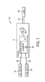
- FIG. 1 illustrates a block diagram of an embodiment of a portion of an engine driven power generation system 10.
- the system 10 includes an engine 12 (e.g., a reciprocating internal combustion engine) having one or more combustion chambers 14 (e.g., 1, 2, 3, 4, 5, 6, 7, 8, 10, 12, 14, 16, 18, 20, or more combustion chambers 14).
- Each combustion chamber 14 is defined by a cylinder 30 and a piston 24 reciprocating in the cylinder 30.
- An oxidant supply 16 is configured to provide a pressurized oxidant 18, such as air, oxygen, oxygen-enriched air, oxygen-reduced air, or any combination thereof, to each combustion chamber 14.
- the combustion chamber 14 is also configured to receive a fuel 20 (e.g., a liquid and/or gaseous fuel) from a fuel supply 22.
- a fuel 20 e.g., a liquid and/or gaseous fuel
- a mixture e.g., fuel-air mixture
- the hot pressurized combustion gases cause a piston 24 adjacent to each combustion chamber 14 to move linearly within the cylinder 30 and convert pressure exerted by the gases into a rotating motion, thereby causing a shaft 26 to rotate.
- the shaft 26 may be coupled to a load 28, which is powered via rotation of the shaft 26.
- the load 28 may be any suitable device that may generate power via the rotational output of the system 10, such as an electrical generator.
- the fuel 20 may be any suitable fuel, such as natural gas, associated petroleum gas, hydrogen, propane, biogas, sewage gas, syngas, landfill gas, coal mine gas, diesel, gasoline, kerosene, or fuel oil for example.
- the system 10 disclosed herein may be adapted for use in stationary applications (e.g., in industrial power generating engines) or in mobile applications (e.g., in automobiles or aircraft).
- the cylinders 30 may include cylinder liners that are separate from an engine block.
- steel liners may be utilized with an aluminum engine block.
- the engine 12 may be a two-stroke engine, three-stroke engine, four-stroke engine, five-stroke engine, or six-stroke engine.
- the engine 12 may also include any number (e.g., 1-24) of combustion chambers 14, pistons 24, and associated cylinders 30 or cylinder liners.
- the system 10 may include a large-scale industrial reciprocating engine having 4, 6, 8, 10, 16, 24 or more pistons 24 reciprocating in cylinders 30 or cylinder liners.
- the cylinders 30, cylinder liners, and respective the pistons 24 may have a diameter of between approximately 10-35 centimeters (cm), 12-18 cm, or about 13.5 to 15 cm.
- the piston 24 may be a steel piston or an aluminum piston with an Ni-Resist ring insert in a top ring groove of the piston 24.
- the system 10 may generate power ranging from 10 kW to 10 MW. Additionally, or in the alternative, the operating speed of the engine may be less than approximately 1800, 1500, 1200, 1000, 900, 800, or 700 RPM.
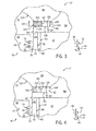
- FIG. 2 is a partial side cross-sectional view of an embodiment of a piston cylinder assembly 40 having a piston 24 disposed within a cylinder liner 42 (e.g., an engine cylinder 30) of the reciprocating engine 12.
- the cylinder liner 42 has an inner annular wall 44 defining a cylindrical cavity 46.
- Directions relative to the engine 12 may be described with reference to an axial axis or direction 48, a radial axis or direction 50, and a circumferential axis or direction 52.
- the piston 24 may include one or more grooves 54 (e.g., annular grooves) extending circumferentially (e.g., in the circumferential direction 52) about the piston 24.
- One or more rings 56 may be positioned in one or more respective grooves 54.
- the one or more rings 56 may be configured to expand and contract in response to high temperatures and high pressure combustion gases during operation of the system 10 and relatively cool temperatures when the system 10 is shut down.
- the one or more grooves 54 and the corresponding one or more rings 56 may have any of a variety of configurations.
- one or more of the grooves 54 and/or corresponding rings 56 may have different configurations, shapes, sizes, and/or functions.
- the piston 24 is attached to a crankshaft 58 via a connecting rod 60 and a pin 62.
- the crankshaft 58 translates the reciprocating linear motion of the piston 24 along the axial axis 48 into a rotating motion 64.
- the combustion chamber 14 is positioned adjacent to a top land 66 of the piston 24 and a cylinder head 68.
- the cylinder head 68 distributes the air 18 and the fuel 20 to the combustion chamber 14, and exhausts combustion products 70 from the combustion chamber 14.
- one or more fuel injectors 72 provides the fuel 20 to the combustion chamber 14, and one or more valves 74 (e.g., intake valves) controls the delivery of air 18 to the combustion chamber 14.
- An exhaust valve 76 controls discharge of combustion products 70 (e.g., exhaust gas) from the engine 12.
- combustion products 70 e.g., exhaust gas
- any suitable elements and/or techniques may be utilized for providing fuel 20 and air 18 to the combustion chamber 14 and/or for discharging the exhaust gas 70.
- combustion of the fuel 20 with the air 18 in the combustion chamber 14 causes the piston 24 to move in a reciprocating manner (e.g., back and forth) in the axial direction 48 within the cavity 46 of the cylinder liner 42.
- the crankshaft 58 rotates (e.g., in direction 64) to power the load 28 (shown in FIG. 1 ), as discussed above.
- a clearance 78 e.g., a radial clearance defining an annular space
- the one or more rings 56 may contact the inner wall 44 of the cylinder liner 42 to retain the fuel 20, the air 18, and a fuel-air mixture within the combustion chamber 14.
- the one or more rings 56 may facilitate maintenance of a suitable pressure within the combustion chamber 14 to enable the expanding hot combustion products 70 to cause the piston 24 to move along the axial axis 48 prior to expulsion through the exhaust valve 76 in a subsequent piston cycle.
- the cylinder liner 42 extends in the axial direction 48 through a support structure 80 (e.g., engine block).
- the cylinder liner 42 may be suspended within an opening 82 or cylindrical bore of the support structure 78 by a flange 84 proximate to the cylinder head 68.
- the flange 84 extends radially between the inner wall 44 and an outer wall 86 of the cylinder liner 42.
- the flange 84 is an annular flange about the liner 42.
- Axial loads e.g., compressive forces
- a seal assembly 86 is arranged between the flange 84 and the cylinder head 68.
- the seal assembly 86 has multiple uses: to transfer loads between the cylinder head 68 and the flange 84, and to isolate the combustion chamber 14 from an external environment 88.
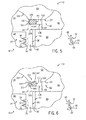
- FIG. 3 is a partial cross-sectional view of an embodiment of the cylinder liner 42, the cylinder head 68, and the seal assembly 86 of the engine 12, taken within line 3-3 of FIG. 2 .
- the seal assembly 86 includes an outer seal 100 (e.g., annular seal) and an inner seal 102 (e.g., annular seal).
- the outer seal 100 interfaces with a first face 104 (e.g., bottom face or axially facing surface) of the cylinder head 68 and a second face 106 (e.g., top face or axially facing surface) of the flange 84.
- the outer seal 100 helps to isolate the combustion chamber 14 from the external environment 88, thereby sealing the air 18, fuel 20, and combustion products 70 within the combustion chamber 14 during combustion.
- the outer seal 100 is axially positioned between the support structure 80 and the cylinder head 68 in the axial direction 48.
- the outer seal 100 is arranged radially between the cylinder head 68 and the flange 84 to enable the outer seal 100 to directly transfer loads between the cylinder head 68 and the support structure 80 without inducing significant bending moments in the flange 84.
- Materials of the outer seal 100 may include, but are not limited to, steel alloys (e.g., stainless steel), titanium alloys, fiber materials, ceramic materials, nickel and other non-ferrous alloys, or any combination thereof.
- the outer seal 100 has a greater hardness than the inner seal 102, and the outer seal 100 has a greater compressive strength than the inner seal 102.
- the greater hardness and/or compressive strength may enable the outer seal 100 to transfer more or substantially the entire load transferred between the cylinder head 68 and the support structure 80, relative to the inner seal 102.
- loads applied to the flange 84 of the cylinder liner 42 near the inner wall 44 may induce bending moments in the flange 84 and may increase a stress concentration within the flange 84, such as at a point 108.
- the outer seal 100 is positioned in the radial direction 50 such that an inner face 110 of the outer seal 100 is radially aligned with or is radially outside of an inner wall 112 of the support structure 80.
- annular crevice volume 114 is defined herein as a space between the first face 104 of the cylinder head 68, the second face 106 of flange 84 of the cylinder liner 42, the inner wall 44 of the cylinder liner 42, and the inner face 110 of the outer seal 100.
- the annular crevice volume 114 extends in the circumferential direction 52 about the combustion chamber 14.
- the inner seal 102 is configured to reduce the annular crevice volume 114. Without the inner seal 102, air 18 and/or fuel 20 may enter the annular crevice volume 114 and fail to react (e.g., combust) during a piston cycle, thereby reducing the combustion efficiency of the piston cylinder assembly 40.
- the proximity of the annular crevice volume 114 to the one or more exhaust valves 76 may increase the probability that the air 18 and/or the fuel 20 that enters the annular crevice volume 114 will be expelled from the combustion chamber 14 without being combusted.
- the inner seal 102 is configured to at least partially or completely fill the annular crevice volume 114, thereby reducing the available space for the air 18 and/or the fuel 20 to be retained and increasing the combustion efficiency of the piston cylinder assembly 40.
- an inner face 116 of the inner seal 102 interfaces with (e.g., is flush with) the inner wall 44 of the cylinder liner 42 and/or an inner wall 118 of the cylinder head 68.
- the inner seal 102 may fill between 10 to 100 percent, 25 to 99 percent, 50 to 95 percent, or 75 to 90 percent of the annular crevice volume 114.
- the inner seal 102 interfaces with the first face 104 of the cylinder head 68, the second face 106 of the flange 84, or any combination thereof.
- the inner seal 102 is positioned in the axial direction 48 between the cylinder head 68 and the flange 84, and the inner seal 102 may be positioned in the radial direction 50 substantially inside the inner wall 112 of the support structure 80 and the outer seal 100.
- the inner seal 102 may be a material that is softer (lower compressive strength) than the outer seal 100.
- the material of the inner seal 102 may be a brazing alloy including, but not limited to, a silver brazing alloy, a bronze brazing alloy, a palladium-based brazing alloy, a gold-based brazing alloy, a copper-based alloy, or a nickel-based brazing alloy.
- the compressive strength of the seal assembly 86 increases in the radial direction 50 outward from the combustion chamber 14 from the inner seal 102 to the outer seal 100.
- the inner seal 102 is configured to transfer less of the load between the cylinder head 68 and the flange 84 than the outer seal 100, thereby reducing bending moments in the flange 84 and reducing stress concentrations at the point 108.
- the inner seal 102 is configured to transfer substantially none of the load between the cylinder head 68 and the flange 84.
- the inner seal 102 may transfer less than 25, 20, 15, 10, or 5 percent of the axial load between the cylinder head 68 and the flange 84.
- a first thickness 120 of the outer seal 100 may be substantially equal to a second thickness 122 of the inner seal 100. That is, rather than using differences in the thicknesses of the outer and inner seals 100, 102 to manage the load distribution across the seal assembly 86, differences in the compressive strengths of the outer and inner seals 100, 102 may facilitate the transfer of axial loads between the cylinder head 68 and the flange 84 to be primarily through the outer seal 100.
- the inner seal 102 is configured to isolate the inner face 110 from the combustion chamber 14. That is, the inner seal 102 may isolate the outer seal 100 from the air 18, the fuel 20, the combustion products 70, or any combination thereof.
- the inner seal 102 may interface with the inner face 110 of the outer seal 100, as shown in FIG. 3 .
- the inner seal 102, the outer seal 100, the cylinder head 68, and the flange 84 may define a sealed cavity 130 that is isolated from the combustion chamber 14 and the external environment 88.
- the inner seal 100 and the cavity 130 reduce the annular crevice volume 114, thereby increasing the combustion efficiency of the piston cylinder assembly 40.
- the inner seal 102 may include a braze material.
- FIG. 5 illustrates a partial cross-sectional view of an embodiment of the seal assembly 86, taken within line 3-3 or FIG. 2 .
- the inner seal 102 of the seal assembly 86 includes a braze material.
- a brazing ring 140 shown in dashed lines, may be disposed in the annular crevice volume 114 between the cylinder head 68 and the flange 84.
- the term brazing ring 140 utilized herein is not limited to an annular component of a braze material.
- the brazing ring 140 may be multiple sections of a braze material disposed in the annular crevice volume 114.
- the brazing ring 140 may be formed utilizing a filler rod of a braze material. Upon heating the brazing ring 140 to a brazing temperature, the brazing ring 140 wets (e.g., fixedly bonds) with the first face 104 of the cylinder head 68 and with the second face 106 of the flange 84, thereby forming a brazed seal 142.
- the brazed seal 142 of the inner seal 102 may be the only portion of the seal assembly 86 that bonds with the cylinder head 68 and the flange 84.
- the brazing ring 140 wets with the inner face 110 of the outer seal 100.
- the brazing ring 140 forms the sealed cavity (see FIG. 4 ).
- the inner face 116 of the brazed seal 142 may be curved and/or flush with the inner walls 44, 118 of the cylinder liner 42 and the cylinder head 68.
- the inner face 116 of the brazed seal 142 is radially offset from the inner wall 44 of the cylinder liner 42, such that the inner face 116 extends into the combustion chamber 14 or is recessed in the annular crevice volume 114.
- the material for the inner seal 102 may be selected for one or more characteristics including, but not limited to, corrosion resistance, bond strength with the materials of the cylinder head 68 and the flange 84, solidus temperature, liquidus temperature, or compressive strength, or any combination thereof.
- the material may have a desired corrosion resistance when exposed to the air 18, the fuel 20, and/or the combustion products 70 at combustion temperatures (e.g., 540 to 870 degrees C).
- the material of the inner seal 102 may be selected to have a compressive strength less than the compressive strength of the outer seal 100, thereby enabling the outer seal 100 to transfer more of the axially compressive loads between the cylinder head 68 and the flange 84 than the inner seal 102.
- the material of the outer seal 100 may be a stainless steel alloy, and the material of the inner seal 102 may be a nickel-based brazing alloy.
- the material of the inner seal 102 may be selected to enable the inner seal 102 to bond with the cylinder head 68 and the flange 84 to isolate the inner face 110 of the outer seal 100 from the combustion chamber 14 through a range of operating temperatures (e.g., 20 to 900 degrees C).
- the inner seal 102 may include a nickel-based or iron-based brazing ring 140 with at least 23 weight percent chromium, at least 6.5 weight percent silicon, and at least 4.5 weight percent phosphorus.
- the composition of the brazing ring 140 may be selected such that the solidus temperature of the brazing ring 140 is greater than approximately 970 degrees C and the liquidus temperature of the brazing ring 140 is less than approximately 1135 degrees C.
- the material of the brazing ring 140 may be selected to enable the brazed seal 142 to maintain the inner seal 102 during normal operating combustion temperatures.
- the solidus and liquidus temperatures of the brazing ring 140 utilized in a stoichiometric combustion reciprocating engine 12 may be higher than the solidus and liquidus temperatures of the brazing ring 140 utilized in a non-stoichiometric (e.g., lean burn) reciprocating engine 12.
- the inner seal 102 may be include, but are not limited to, a brazing alloy listed in Tables 1-5, available from Johnson Matthey Metal Joining of Royston, England.
- a brazing alloy listed in Tables 1-5 available from Johnson Matthey Metal Joining of Royston, England.
- nickel-based, copper-based, and palladium-based brazing alloys may have lower costs than gold-based and silver-based brazing alloys.
- gold-based and silver-based brazing alloys may increase ductility of the inner seal 102.
- the material of the inner seal 102 may be selected based at least in part on the melting range of the brazing alloy.
- the brazing alloys listed in Tables 1-5 have melting temperatures between approximately 600 to 1230 degrees C.
- the brazing ring 140 of the inner seal 102 of the seal assembly 86 wets (e.g., bond) with the first face 104 of the cylinder head 68 and/or the second face 106 of the flange 84 at the brazing temperature.
- the material of the brazing ring 140 is selected such that the brazing temperature is within a range of combustion temperatures that the inner seal 102 is exposed to during operation of the piston cylinder assembly 40. For example, during initial operation of the reciprocating engine 12, the combustion of the air 18 and the fuel 20 in the combustion chamber 14 heats the brazing ring 140 to the brazing temperature (e.g., approximately 800 degrees C).
- the initial operation of the reciprocating engine 12 may be controlled to a greater temperature than a typical operating temperature, such that the brazing ring 140 is heated to wet (e.g., bond) with the cylinder head 68 and the flange 84 in the desired position.
- the reciprocating engine 12 may be controlled to operate at the typical operating temperature, thereby retaining the brazed seal in the annular crevice volume.
- the material of the brazing ring 140 is selected such that the brazing temperature is greater than a range of combustion temperatures that the inner seal 102 is exposed to during operation of the piston cylinder assembly 40.
- the brazing ring 140 may be inserted in the desired position between the cylinder head 68 and the flange 84 of the cylinder liner 42, then the brazing ring 140 may be heated to the brazing temperature.
- the brazing ring 140 may be heated to the brazing temperature via a torch, an inductive process, or any combination thereof. Utilizing a brazing ring 140 with a brazing temperature greater than the range of combustion temperatures of the engine 12 may enable the brazed seal 142 to endure sustained operation at the combustion temperatures without melting.
- FIG. 6 illustrates a cross-sectional view of the seal assembly 86 of the piston cylinder assembly 40, taken within line 3-3 of FIG. 2 .
- FIG. 6 illustrates an embodiment of the seal assembly 86 in which the inner seal 102 includes a shield 150 (e.g., an annular shielding ring having a U-shaped or C-shaped cross-section 151).
- the shield 150 is disposed in the annular crevice volume 114 inside the outer seal 100 in the radial direction 50.
- the shield 150 may be a heat resistant material that may readily endure combustion temperatures.
- the shield may include, but is not limited to, steel.
- the shield 150 at least partially isolates an inner sealant 152 (e.g., brazed seal 142) from the combustion chamber 14.
- the shield 150 may at least partially isolate the inner sealant 152 from potentially corrosive materials, such as the fuel 20 or the combustion products 70.
- the shield 150 interfaces with the first surface 104 of the cylinder head 68 and the second surface 106 of the flange 84.
- a thickness 154 and/or a shape of the shield 150 are selected to reduce the load transferred by the shield 150 between the cylinder head 68 and the flange 84, thereby reducing the stress concentration at the point 108. While the shield 150 illustrated in FIG.
- the shield 150 may include, but are not limited, to an I-shape, a J-shape, an L-shape, an M-shape, an S-shape, a T-shape, a V-shape, an X-shape, and so forth. That is, the shield 150 is configured to shield the inner sealant 152 and/or the outer seal 100 from the combustion chamber 14, and the shield 150 is not configured to transfer an axial load (e.g., compressive load) between the cylinder head 68 and the flange 84.
- an axial load e.g., compressive load
- the shield 150 may facilitate retaining the sealant material 152 within the annular crevice volume 114. Additionally, or in the alternative, the sealant material 152 may interface with the shield 150 and another surface (e.g., first surface 104, second surface 106, inner surface 110), thereby retaining the shield 150.
- the sealant material 152 may be the brazed seal 142.
- the inner seal 102 is configured to reduce the annular crevice volume 114, and may be configured to isolate the inner face 110 of the outer seal 100 from the combustion chamber 14. Furthermore, the inner seal 102 is configured to transfer less of the load between the cylinder head 68 and the flange 84 than the outer seal 100, thereby reducing bending moments in the flange 84 and reducing stress concentrations at the point 108.
- a method of utilizing the seal assembly 86 may include reducing an annular crevice volume 114 with an inner seal 102 of the seal assembly 86. Additionally, or in the alternative, the method of utilizing the seal assembly 86 may include isolating, with the inner seal 102, the inner face 110 of the outer seal from the combustion chamber 14.
- the materials of the inner seal 102 and the outer seal 100 are selected to facilitate transferring axial loads (e.g., compressive loads) between the cylinder head 68 and support structure, via the flange 84 of the cylinder liner 42, primarily through the outer seal 100. That is, the outer seal 100 is configured to transfer more of the load between the cylinder head 68 and the cylinder liner 42 than the inner seal 102.
- the outer seal is configured to transfer more of the axial compressive load between the cylinder head and the cylinder liner than the inner seal, thereby reducing stress that may be otherwise concentrated at a point in the flange of the cylinder liner due to induced bending moments.
- the inner seal isolates the inner face of the outer seal from the combustion chamber.
- a shield of the inner seal may isolate a sealant material of the inner seal from the combustion chamber.
Landscapes
- Engineering & Computer Science (AREA)
- General Engineering & Computer Science (AREA)
- Mechanical Engineering (AREA)
- Chemical & Material Sciences (AREA)
- Combustion & Propulsion (AREA)
- Cylinder Crankcases Of Internal Combustion Engines (AREA)
- Gasket Seals (AREA)
Applications Claiming Priority (1)
| Application Number | Priority Date | Filing Date | Title |
|---|---|---|---|
| US14/448,685 US20160032862A1 (en) | 2014-07-31 | 2014-07-31 | System and method for reduced crevice volume of a piston cylinder assembly |
Publications (2)
| Publication Number | Publication Date |
|---|---|
| EP2980392A2 true EP2980392A2 (de) | 2016-02-03 |
| EP2980392A3 EP2980392A3 (de) | 2016-03-02 |
Family
ID=54065660
Family Applications (1)
| Application Number | Title | Priority Date | Filing Date |
|---|---|---|---|
| EP15178534.2A Withdrawn EP2980392A3 (de) | 2014-07-31 | 2015-07-27 | System und verfahren für vermindertes spaltenvolumen einer kolbenzylinderanordnung |
Country Status (6)
| Country | Link |
|---|---|
| US (1) | US20160032862A1 (de) |
| EP (1) | EP2980392A3 (de) |
| JP (1) | JP2016035262A (de) |
| KR (1) | KR20160016640A (de) |
| CN (1) | CN105317583A (de) |
| BR (1) | BR102015018269A2 (de) |
Cited By (3)
| Publication number | Priority date | Publication date | Assignee | Title |
|---|---|---|---|---|
| US20160252044A1 (en) * | 2015-02-27 | 2016-09-01 | Avl Powertrain Engineering, Inc. | Engine Block Construction For Opposed Piston Engine |
| US10036344B2 (en) | 2015-02-27 | 2018-07-31 | Avl Powertrain Engineering, Inc. | Opposed piston two stroke engine liner construction |
| AT17085U1 (de) * | 2019-12-19 | 2021-05-15 | Avl List Gmbh | Brennkraftmaschine mit Zylinderkopfdichtung |
Families Citing this family (2)
| Publication number | Priority date | Publication date | Assignee | Title |
|---|---|---|---|---|
| US10865734B2 (en) | 2017-12-06 | 2020-12-15 | Ai Alpine Us Bidco Inc | Piston assembly with offset tight land profile |
| JP7338734B1 (ja) * | 2022-04-13 | 2023-09-05 | いすゞ自動車株式会社 | 内燃機関 |
Family Cites Families (6)
| Publication number | Priority date | Publication date | Assignee | Title |
|---|---|---|---|---|
| JPS56113145U (de) * | 1980-02-01 | 1981-09-01 | ||
| DE3122904C2 (de) * | 1981-06-10 | 1984-11-08 | Audi Nsu Auto Union Ag, 7107 Neckarsulm | Lösbare mittels Schrauben verspannte Zylinderkopf-Zylinder-Verbindung |
| DE10321034B3 (de) * | 2003-05-10 | 2005-01-13 | Daimlerchrysler Ag | Hubkolbenbrennkraftmaschine |
| SE534911C2 (sv) * | 2010-06-16 | 2012-02-14 | Scania Cv Ab | Arrangemang i en förbränningsmotor |
| DE102012013379A1 (de) * | 2012-07-04 | 2014-01-09 | Mtu Friedrichshafen Gmbh | Einlage und Verbrennungsmotor mit Einlage |
| EP2700801A1 (de) * | 2012-08-23 | 2014-02-26 | Wärtsilä Schweiz AG | Zylinderliner für eine Hubkolbenbrennkraftmaschine, Verfahren zur Herstellung eines Stützrings für einen Zylinderliner, sowie Stützring |
-
2014
- 2014-07-31 US US14/448,685 patent/US20160032862A1/en not_active Abandoned
-
2015
- 2015-07-27 EP EP15178534.2A patent/EP2980392A3/de not_active Withdrawn
- 2015-07-28 JP JP2015148196A patent/JP2016035262A/ja active Pending
- 2015-07-29 KR KR1020150107050A patent/KR20160016640A/ko not_active Withdrawn
- 2015-07-30 BR BR102015018269A patent/BR102015018269A2/pt not_active Application Discontinuation
- 2015-07-31 CN CN201510461695.8A patent/CN105317583A/zh active Pending
Non-Patent Citations (1)
| Title |
|---|
| None |
Cited By (4)
| Publication number | Priority date | Publication date | Assignee | Title |
|---|---|---|---|---|
| US20160252044A1 (en) * | 2015-02-27 | 2016-09-01 | Avl Powertrain Engineering, Inc. | Engine Block Construction For Opposed Piston Engine |
| US10036344B2 (en) | 2015-02-27 | 2018-07-31 | Avl Powertrain Engineering, Inc. | Opposed piston two stroke engine liner construction |
| US10072604B2 (en) * | 2015-02-27 | 2018-09-11 | Avl Powertrain Engineering, Inc. | Engine block construction for opposed piston engine |
| AT17085U1 (de) * | 2019-12-19 | 2021-05-15 | Avl List Gmbh | Brennkraftmaschine mit Zylinderkopfdichtung |
Also Published As
| Publication number | Publication date |
|---|---|
| US20160032862A1 (en) | 2016-02-04 |
| CN105317583A (zh) | 2016-02-10 |
| BR102015018269A2 (pt) | 2016-05-31 |
| KR20160016640A (ko) | 2016-02-15 |
| JP2016035262A (ja) | 2016-03-17 |
| EP2980392A3 (de) | 2016-03-02 |
Similar Documents
| Publication | Publication Date | Title |
|---|---|---|
| EP2980392A2 (de) | System und verfahren für vermindertes spaltenvolumen einer kolbenzylinderanordnung | |
| JP5531159B2 (ja) | 排ガスターボチャージャ | |
| EP1160512A3 (de) | Bruchfeste Trageinrichtung für eine Hula-Dichtung in einer Gasturbine und entsprechendes Verfahren | |
| CN1508396A (zh) | 供热膨胀系数不同的构件之间的连接或空间密封的结构 | |
| CN105386887B (zh) | 用于控制往复式发动机的气缸套和活塞上的沉积物的系统 | |
| US9845765B2 (en) | Piston assembly for a reciprocating engine | |
| US11846228B2 (en) | Pre-combustion chamber apparatus and method for pre-combustion | |
| CN105822449A (zh) | 高效二冲程发动机 | |
| CN102803681A (zh) | 隔热燃烧室 | |
| US11125095B2 (en) | Sliding seal | |
| US8388313B2 (en) | Extraction cavity wing seal | |
| FI126955B (en) | FE-based composition, precursor component and process for producing precursor component | |
| JP2021085408A (ja) | 大型エンジンのためのピストン・リング、及び大型エンジン | |
| JP3639779B2 (ja) | 内燃機関及び内燃機関に用いられる部品 | |
| CN201050417Y (zh) | 摩托车发动机的活塞与汽缸的配合结构 | |
| JP2008014424A (ja) | ピストンリングの構造 | |
| CN203347936U (zh) | 船用发动机钢顶铝裙组合活塞 | |
| CN120351529A (zh) | 一种高油气比燃烧室 | |
| Rivers et al. | Pistons and cylinders made of carbon-carbon composite materials | |
| CN119554152A (zh) | 一种降ch原排的非对称小侧隙活塞结构 | |
| JP2021006708A (ja) | 燃料噴射弁及び燃料噴射弁を備える内燃機関 |
Legal Events
| Date | Code | Title | Description |
|---|---|---|---|
| PUAL | Search report despatched |
Free format text: ORIGINAL CODE: 0009013 |
|
| PUAI | Public reference made under article 153(3) epc to a published international application that has entered the european phase |
Free format text: ORIGINAL CODE: 0009012 |
|
| AK | Designated contracting states |
Kind code of ref document: A2 Designated state(s): AL AT BE BG CH CY CZ DE DK EE ES FI FR GB GR HR HU IE IS IT LI LT LU LV MC MK MT NL NO PL PT RO RS SE SI SK SM TR |
|
| AX | Request for extension of the european patent |
Extension state: BA ME |
|
| AK | Designated contracting states |
Kind code of ref document: A3 Designated state(s): AL AT BE BG CH CY CZ DE DK EE ES FI FR GB GR HR HU IE IS IT LI LT LU LV MC MK MT NL NO PL PT RO RS SE SI SK SM TR |
|
| AX | Request for extension of the european patent |
Extension state: BA ME |
|
| RIC1 | Information provided on ipc code assigned before grant |
Ipc: F02F 1/16 20060101ALI20160127BHEP Ipc: F02F 1/00 20060101ALI20160127BHEP Ipc: F02F 11/00 20060101AFI20160127BHEP |
|
| 17P | Request for examination filed |
Effective date: 20160902 |
|
| RBV | Designated contracting states (corrected) |
Designated state(s): AL AT BE BG CH CY CZ DE DK EE ES FI FR GB GR HR HU IE IS IT LI LT LU LV MC MK MT NL NO PL PT RO RS SE SI SK SM TR |
|
| 17Q | First examination report despatched |
Effective date: 20170324 |
|
| STAA | Information on the status of an ep patent application or granted ep patent |
Free format text: STATUS: THE APPLICATION IS DEEMED TO BE WITHDRAWN |
|
| 18D | Application deemed to be withdrawn |
Effective date: 20170804 |