EP2980388A1 - Drive control device - Google Patents
Drive control device Download PDFInfo
- Publication number
- EP2980388A1 EP2980388A1 EP15746693.9A EP15746693A EP2980388A1 EP 2980388 A1 EP2980388 A1 EP 2980388A1 EP 15746693 A EP15746693 A EP 15746693A EP 2980388 A1 EP2980388 A1 EP 2980388A1
- Authority
- EP
- European Patent Office
- Prior art keywords
- creep
- control
- rotational speed
- control unit
- engine
- Prior art date
- Legal status (The legal status is an assumption and is not a legal conclusion. Google has not performed a legal analysis and makes no representation as to the accuracy of the status listed.)
- Granted
Links
Images


Classifications
-
- F—MECHANICAL ENGINEERING; LIGHTING; HEATING; WEAPONS; BLASTING
- F02—COMBUSTION ENGINES; HOT-GAS OR COMBUSTION-PRODUCT ENGINE PLANTS
- F02D—CONTROLLING COMBUSTION ENGINES
- F02D41/00—Electrical control of supply of combustible mixture or its constituents
- F02D41/02—Circuit arrangements for generating control signals
- F02D41/0205—Circuit arrangements for generating control signals using an auxiliary engine speed control
-
- B—PERFORMING OPERATIONS; TRANSPORTING
- B60—VEHICLES IN GENERAL
- B60W—CONJOINT CONTROL OF VEHICLE SUB-UNITS OF DIFFERENT TYPE OR DIFFERENT FUNCTION; CONTROL SYSTEMS SPECIALLY ADAPTED FOR HYBRID VEHICLES; ROAD VEHICLE DRIVE CONTROL SYSTEMS FOR PURPOSES NOT RELATED TO THE CONTROL OF A PARTICULAR SUB-UNIT
- B60W30/00—Purposes of road vehicle drive control systems not related to the control of a particular sub-unit, e.g. of systems using conjoint control of vehicle sub-units
- B60W30/18—Propelling the vehicle
- B60W30/18009—Propelling the vehicle related to particular drive situations
- B60W30/18027—Drive off, accelerating from standstill
-
- B—PERFORMING OPERATIONS; TRANSPORTING
- B60—VEHICLES IN GENERAL
- B60W—CONJOINT CONTROL OF VEHICLE SUB-UNITS OF DIFFERENT TYPE OR DIFFERENT FUNCTION; CONTROL SYSTEMS SPECIALLY ADAPTED FOR HYBRID VEHICLES; ROAD VEHICLE DRIVE CONTROL SYSTEMS FOR PURPOSES NOT RELATED TO THE CONTROL OF A PARTICULAR SUB-UNIT
- B60W30/00—Purposes of road vehicle drive control systems not related to the control of a particular sub-unit, e.g. of systems using conjoint control of vehicle sub-units
- B60W30/18—Propelling the vehicle
- B60W30/18009—Propelling the vehicle related to particular drive situations
- B60W30/18063—Creeping
-
- B—PERFORMING OPERATIONS; TRANSPORTING
- B60—VEHICLES IN GENERAL
- B60W—CONJOINT CONTROL OF VEHICLE SUB-UNITS OF DIFFERENT TYPE OR DIFFERENT FUNCTION; CONTROL SYSTEMS SPECIALLY ADAPTED FOR HYBRID VEHICLES; ROAD VEHICLE DRIVE CONTROL SYSTEMS FOR PURPOSES NOT RELATED TO THE CONTROL OF A PARTICULAR SUB-UNIT
- B60W30/00—Purposes of road vehicle drive control systems not related to the control of a particular sub-unit, e.g. of systems using conjoint control of vehicle sub-units
- B60W30/18—Propelling the vehicle
- B60W30/188—Controlling power parameters of the driveline, e.g. determining the required power
- B60W30/1884—Avoiding stall or overspeed of the engine
-
- F—MECHANICAL ENGINEERING; LIGHTING; HEATING; WEAPONS; BLASTING
- F02—COMBUSTION ENGINES; HOT-GAS OR COMBUSTION-PRODUCT ENGINE PLANTS
- F02D—CONTROLLING COMBUSTION ENGINES
- F02D29/00—Controlling engines, such controlling being peculiar to the devices driven thereby, the devices being other than parts or accessories essential to engine operation, e.g. controlling of engines by signals external thereto
- F02D29/02—Controlling engines, such controlling being peculiar to the devices driven thereby, the devices being other than parts or accessories essential to engine operation, e.g. controlling of engines by signals external thereto peculiar to engines driving vehicles; peculiar to engines driving variable pitch propellers
-
- B—PERFORMING OPERATIONS; TRANSPORTING
- B60—VEHICLES IN GENERAL
- B60W—CONJOINT CONTROL OF VEHICLE SUB-UNITS OF DIFFERENT TYPE OR DIFFERENT FUNCTION; CONTROL SYSTEMS SPECIALLY ADAPTED FOR HYBRID VEHICLES; ROAD VEHICLE DRIVE CONTROL SYSTEMS FOR PURPOSES NOT RELATED TO THE CONTROL OF A PARTICULAR SUB-UNIT
- B60W2510/00—Input parameters relating to a particular sub-units
- B60W2510/02—Clutches
- B60W2510/0241—Clutch slip, i.e. difference between input and output speeds
-
- B—PERFORMING OPERATIONS; TRANSPORTING
- B60—VEHICLES IN GENERAL
- B60W—CONJOINT CONTROL OF VEHICLE SUB-UNITS OF DIFFERENT TYPE OR DIFFERENT FUNCTION; CONTROL SYSTEMS SPECIALLY ADAPTED FOR HYBRID VEHICLES; ROAD VEHICLE DRIVE CONTROL SYSTEMS FOR PURPOSES NOT RELATED TO THE CONTROL OF A PARTICULAR SUB-UNIT
- B60W2510/00—Input parameters relating to a particular sub-units
- B60W2510/06—Combustion engines, Gas turbines
- B60W2510/0638—Engine speed
-
- B—PERFORMING OPERATIONS; TRANSPORTING
- B60—VEHICLES IN GENERAL
- B60W—CONJOINT CONTROL OF VEHICLE SUB-UNITS OF DIFFERENT TYPE OR DIFFERENT FUNCTION; CONTROL SYSTEMS SPECIALLY ADAPTED FOR HYBRID VEHICLES; ROAD VEHICLE DRIVE CONTROL SYSTEMS FOR PURPOSES NOT RELATED TO THE CONTROL OF A PARTICULAR SUB-UNIT
- B60W2510/00—Input parameters relating to a particular sub-units
- B60W2510/10—Change speed gearings
- B60W2510/1015—Input shaft speed, e.g. turbine speed
-
- B—PERFORMING OPERATIONS; TRANSPORTING
- B60—VEHICLES IN GENERAL
- B60W—CONJOINT CONTROL OF VEHICLE SUB-UNITS OF DIFFERENT TYPE OR DIFFERENT FUNCTION; CONTROL SYSTEMS SPECIALLY ADAPTED FOR HYBRID VEHICLES; ROAD VEHICLE DRIVE CONTROL SYSTEMS FOR PURPOSES NOT RELATED TO THE CONTROL OF A PARTICULAR SUB-UNIT
- B60W2540/00—Input parameters relating to occupants
- B60W2540/12—Brake pedal position
-
- B—PERFORMING OPERATIONS; TRANSPORTING
- B60—VEHICLES IN GENERAL
- B60W—CONJOINT CONTROL OF VEHICLE SUB-UNITS OF DIFFERENT TYPE OR DIFFERENT FUNCTION; CONTROL SYSTEMS SPECIALLY ADAPTED FOR HYBRID VEHICLES; ROAD VEHICLE DRIVE CONTROL SYSTEMS FOR PURPOSES NOT RELATED TO THE CONTROL OF A PARTICULAR SUB-UNIT
- B60W2710/00—Output or target parameters relating to a particular sub-units
- B60W2710/06—Combustion engines, Gas turbines
- B60W2710/0644—Engine speed
-
- B—PERFORMING OPERATIONS; TRANSPORTING
- B60—VEHICLES IN GENERAL
- B60W—CONJOINT CONTROL OF VEHICLE SUB-UNITS OF DIFFERENT TYPE OR DIFFERENT FUNCTION; CONTROL SYSTEMS SPECIALLY ADAPTED FOR HYBRID VEHICLES; ROAD VEHICLE DRIVE CONTROL SYSTEMS FOR PURPOSES NOT RELATED TO THE CONTROL OF A PARTICULAR SUB-UNIT
- B60W2710/00—Output or target parameters relating to a particular sub-units
- B60W2710/06—Combustion engines, Gas turbines
- B60W2710/0666—Engine torque
-
- B—PERFORMING OPERATIONS; TRANSPORTING
- B60—VEHICLES IN GENERAL
- B60Y—INDEXING SCHEME RELATING TO ASPECTS CROSS-CUTTING VEHICLE TECHNOLOGY
- B60Y2400/00—Special features of vehicle units
- B60Y2400/70—Gearings
- B60Y2400/71—Manual or semi-automatic, e.g. automated manual transmissions
-
- F—MECHANICAL ENGINEERING; LIGHTING; HEATING; WEAPONS; BLASTING
- F02—COMBUSTION ENGINES; HOT-GAS OR COMBUSTION-PRODUCT ENGINE PLANTS
- F02D—CONTROLLING COMBUSTION ENGINES
- F02D2250/00—Engine control related to specific problems or objectives
- F02D2250/18—Control of the engine output torque
-
- F—MECHANICAL ENGINEERING; LIGHTING; HEATING; WEAPONS; BLASTING
- F02—COMBUSTION ENGINES; HOT-GAS OR COMBUSTION-PRODUCT ENGINE PLANTS
- F02D—CONTROLLING COMBUSTION ENGINES
- F02D41/00—Electrical control of supply of combustible mixture or its constituents
- F02D41/02—Circuit arrangements for generating control signals
- F02D41/021—Introducing corrections for particular conditions exterior to the engine
- F02D41/0215—Introducing corrections for particular conditions exterior to the engine in relation with elements of the transmission
- F02D41/022—Introducing corrections for particular conditions exterior to the engine in relation with elements of the transmission in relation with the clutch status
Definitions
- the present invention relates to a drive control device. Especially, the present invention relates to a drive control device for executing a creep control that increases a torque in order to assist the start at the time of the start of a vehicle.
- an automated manual transmission that includes an actuator for automatically executing an engagement and disengagement operation of the clutch or a shift operation.
- AMT automated manual transmission
- a drive control device As a technology for executing the creep control of the AMT, a drive control device is disclosed in Japanese Patent Laid-Open Publication No. 2002-096658 .
- This drive control device causes a clutch to be slip-engaged when a brake release operation is detected. In this way, a driving force is transmitted, and thus, a vehicle is driven.
- Patent Document 1 Japanese Patent Laid-Open Publication No. 2002-096658
- the AMT does not include a torque converter, unlike an automatic transmission (AT). Therefore, in such AMT, a creep control is executed on the basis of a creep torque including a torque or the like for starting a vehicle. At this time, it is necessary to generate a creep torque of a torque demand amount in an engine. In the creep control, the creep torque generated in the engine is transmitted to a driving wheel by causing a clutch to be slip-engaged (semi-connected state), thereby assisting the start of the vehicle.
- the present invention aims to execute the creep control based on a correction amount that is obtained by correcting a demand amount of the creep torque, under the condition that the demand amount for the creep torque is small.
- the present invention provides a drive control device for executing a creep control based on a torque demand amount of a creep torque.
- the drive control device includes a control unit configured to execute the creep control based on a predefined torque demand amount when a request for actuation of the creep control is detected; and a detection unit configured to detect an engine rotational speed of a vehicle. When the engine rotational speed is greater than a target engine rotational speed, the control unit executes the creep control based on a correction amount that is obtained by correcting the predefined torque demand amount.
- the present invention can suppress an increase in an engine rotational speed due to the excessive torque up of an engine, so that a stable fuel consumption performance and drivability can be secured.
- Figs. 1 to 4 show an embodiment of the present invention.
- an engine 1 to be mounted on a vehicle is connected to an automated manual transmission 3 (hereinafter, referred to as "AMT") through a clutch 2.
- AMT automated manual transmission
- the amount of intake air is adjusted by an electronic control throttle valve 4.
- a driving force is generated by combustion of fuel that is supplied in accordance with the amount of intake air.
- the clutch 2 is configured by a friction clutch, or the like.
- the engagement and disengagement of transmission of the driving force is executed by a first actuator 5.
- the AMT 3 is configured by multi-stage gear trains having different gear ratios or a belt pulley where a gear ratio can be continuously changed, etc.
- a shift operation is controlled by a second actuator 6, and thus, the switching of the gear ratio is executed.
- the driving force generated by the engine 1 is inputted to the AMT 3 through the clutch 2 and then converted into a rotational speed and a torque, which correspond to the gear ratio.
- a differential 7 the driving force outputted from the AMT 3 is transmitted to a driving wheel 9 through a drive axle 8, thereby causing the vehicle to be driven.
- An engine control unit 10 controls a throttle opening degree of an electronic control throttle valve 4 and thus controls a torque that is generated by the engine 1.
- a clutch control unit 11 controls an operation of the first actuator 5 and thus controls the engagement and disengagement of the clutch 2.
- a transmission control unit 12 controls an operation of the second actuator 6 and thus controls a shift operation in the AMT 3.
- the engine control unit 10, the clutch control unit 11 and the transmission control unit 12 are collectively controlled by being connected to a drive control device 13 through an in-vehicle LAN such as CAN (Control Area Network).
- the drive control device 13 executes a creep control based on a torque demand amount of a creep torque that includes a torque for starting a vehicle at the time of the start of the vehicle.
- the drive control device 13 controls an operation of the electronic control throttle valve 4 by the engine control unit 10 and thus causes the creep torque of the torque demand amount to be generated in the engine 1.
- the drive control device 13 controls an operation of the first actuator 5 by the clutch control unit 11 and thus causes the clutch 2 to be slip-engaged (semi-connected state).
- the drive control device 13 includes a control unit 14.
- the control unit 14 executes the creep control based on a predefined torque demand amount when a request for actuation of the creep control is detected. As shown in Fig. 2 , the control unit 14 executes the creep control by the input of a signal related to an engine rotational speed, a signal related to a target engine rotational speed, a creep control signal and a signal related to a clutch rotational speed.
- the engine rotational speed is detected by an engine rotational speed detection unit 15 provided in the engine 1.
- the target engine rotational speed refers to a target value of an engine rotational speed for the request torque from a driver.
- the target engine rotational speed is calculated by a target engine rotational speed calculation unit 16 included in the engine control unit 11, based on the throttle opening degree of the electronic control throttle valve 4, for example.
- the creep control signal is composed of an ON signal indicating the creep control in an actuation state and an OFF signal indicating the creep control in a non-actuation state. Further, the creep control signal can be set on the basis of a brake actuation signal of a brake switch 17. For example, the brake actuation signal is switched on when a brake is depressed and is switched off when the brake operation is released.
- the creep control is set to the non-actuation state when the brake actuation signal is the ON signal, and the creep control is set to the actuation state when the brake actuation signal is the OFF signal.
- the clutch rotational speed is detected by a clutch rotational speed detection unit 18 provided in an output-side member of the clutch 2.
- the control unit 14 calculates a correction amount that is obtained by correcting a predefined torque demand amount in the creep torque. Specifically, the control unit 14 calculates a correction amount that is corrected so as to reduce the predefined torque demand amount.
- the control unit 14 executes the creep control by outputting the correction amount calculated to the engine control unit 10.
- the engine control unit 10 controls the throttle opening degree of the electronic control throttle valve 4 in accordance with the correction amount to be inputted, thereby causing the creep torque of the correction amount to be generated in the engine 1.
- the control unit 14 starts a program for the creep control when receiving an ON signal of an ignition switch, for example (S01).
- the control unit 14 detects whether or not there is a request for actuation of the creep control (S02). Specifically, the control unit 14 detects whether or not the creep control is changed from the non-actuation state to the actuation state, i.e., whether or not the creep control signal is changed from the OFF signal to the ON signal. Further, the control unit 14 may detect whether or not the brake actuation signal is changed from the ON signal to the OFF signal.
- control unit 14 may be configured to detect whether or not to receive at least one of the ON signal of the creep control signal or the OFF signal of the brake actuation signal. In this case, the control unit 14 does not check the changing state of the creep control signal and the brake actuation signal, but checks whether or not to receive a predetermined signal.
- control unit 14 detects whether or not the request for the actuation of the creep control is made.
- the control unit 14 ends the creep control (S07). Specifically, the control unit 14 ends the creep control when the OFF signal of the creep control signal or the ON signal of the brake actuation signal is received.
- the control unit 14 detects whether or not a correction execution condition for correcting a predefined torque demand amount is established (S03). Specifically, the control unit 14 detects that the correction execution condition is established when the engine rotational speed is greater than the target engine rotational speed.
- the control unit 14 controls the engine torque based on the predefined torque demand amount (S06). Specifically, when it is detected that the engine rotational speed is equal to or less than the target engine rotational speed, the control unit 14 outputs a command signal to the engine control unit 10 so as to control the engine torque based on the predefined torque demand amount.
- the engine control unit 10 controls the electronic control throttle valve 4 so that the throttle opening degree corresponds to the predefined torque demand amount. In this way, the control unit 14 causes the creep torque of the predefined torque demand amount to be generated in the engine 1, and then, ends the creep control (S07).
- the control unit 14 calculates a correction amount that is obtained by correcting the predefined torque demand amount (S04). Specifically, when it is detected that the engine rotational speed is greater than the target engine rotational speed, the control unit 14 calculates a correction amount that is obtained by correcting the predefined torque demand amount on the basis of the engine rotational speed, the target engine rotational speed and the clutch rotational speed. The control unit 14 calculates, as the correction amount, a value that is corrected so as to reduce the predefined torque demand amount. As indicated by t2, t4 and t6 in Fig. 4 , the correction amount is calculated as a value that is obtained by correcting the predefined torque demand amount so as to be further reduced as the deviation between the engine rotational speed and the target engine rotational speed becomes greater.
- the control unit 14 outputs a command signal to the engine control unit 10 so as to execute the engine torque control based on the correction amount.
- the engine control unit 10 controls the electronic control throttle valve 4 so that the throttle opening degree corresponds to the correction amount (S05).
- the control unit 14 causes the creep torque of the correction amount to be generated in the engine 1, and then, ends the creep control (S07).
- the clutch control unit 11 causes the clutch 2 to be slip-engaged (semi-connected state).
- the clutch control unit 11 transmits the creep torque generated in the engine 1 to the driving wheel 9, thereby assisting the start of the vehicle.
- the drive control device 13 calculates the correction amount corrected so as to reduce the predefined torque demand amount and controls the electronic control throttle valve 4 of the engine 1 so that the throttle opening degree corresponds to the correction amount. In this way, the blowing up of the engine rotational speed is suppressed.
- the drive control device 13 can suppress an increase in the engine rotational speed due to excessive torque up of the engine 1 at the time of the execution of the creep control, so that a stable fuel consumption performance and drivability can be secured.
Landscapes
- Engineering & Computer Science (AREA)
- Mechanical Engineering (AREA)
- Automation & Control Theory (AREA)
- Transportation (AREA)
- General Engineering & Computer Science (AREA)
- Combustion & Propulsion (AREA)
- Chemical & Material Sciences (AREA)
- Control Of Vehicle Engines Or Engines For Specific Uses (AREA)
- Hydraulic Clutches, Magnetic Clutches, Fluid Clutches, And Fluid Joints (AREA)
- Combined Controls Of Internal Combustion Engines (AREA)
- Electrical Control Of Air Or Fuel Supplied To Internal-Combustion Engine (AREA)
- Control Of Transmission Device (AREA)
- Control Of Driving Devices And Active Controlling Of Vehicle (AREA)
Abstract
Description
- The present invention relates to a drive control device. Especially, the present invention relates to a drive control device for executing a creep control that increases a torque in order to assist the start at the time of the start of a vehicle.
- Conventionally, in a manual transmission that transmits a driving force of an engine mounted on a vehicle through a clutch, there is known an automated manual transmission (AMT) that includes an actuator for automatically executing an engagement and disengagement operation of the clutch or a shift operation.
- Further, in the automated manual transmission (hereinafter, referred to as "AMT"), there is known a technology that is adapted to secure startability by executing a creep control at the time of the start of a vehicle.
- As a technology for executing the creep control of the AMT, a drive control device is disclosed in
Japanese Patent Laid-Open Publication No. 2002-096658 - Patent Document 1:
Japanese Patent Laid-Open Publication No. 2002-096658 - By the way, the AMT does not include a torque converter, unlike an automatic transmission (AT). Therefore, in such AMT, a creep control is executed on the basis of a creep torque including a torque or the like for starting a vehicle. At this time, it is necessary to generate a creep torque of a torque demand amount in an engine. In the creep control, the creep torque generated in the engine is transmitted to a driving wheel by causing a clutch to be slip-engaged (semi-connected state), thereby assisting the start of the vehicle.
- However, under the condition that the torque demand amount for the creep torque is small, for example, in the case where an engine rotational speed at the time of the actuation of the creep control is greater than a target engine rotational speed, an excessive torque up of an engine is caused when the creep control is executed by a predefined creep torque that is predetermined. As a result, there is a possibility that the engine rotational speed is increased, and hence, a fuel consumption performance or drivability is degraded.
- Therefore, the present invention aims to execute the creep control based on a correction amount that is obtained by correcting a demand amount of the creep torque, under the condition that the demand amount for the creep torque is small.
- The present invention provides a drive control device for executing a creep control based on a torque demand amount of a creep torque. The drive control device includes a control unit configured to execute the creep control based on a predefined torque demand amount when a request for actuation of the creep control is detected; and a detection unit configured to detect an engine rotational speed of a vehicle. When the engine rotational speed is greater than a target engine rotational speed, the control unit executes the creep control based on a correction amount that is obtained by correcting the predefined torque demand amount.
- The present invention can suppress an increase in an engine rotational speed due to the excessive torque up of an engine, so that a stable fuel consumption performance and drivability can be secured.
-
-
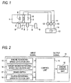
Fig. 1 is a system configuration diagram of a drive control device. (Embodiment) -
Fig. 2 is a view showing an input signal and an output signal of the drive control device. (Embodiment) -
Fig. 3 is a flow chart of a creep control of the drive control device. (Embodiment) -
Fig. 4 is a time chart of the creep control of the drive control device. (Embodiment) - Hereinafter, an embodiment of the present invention will be described with reference to the drawings.
-
Figs. 1 to 4 show an embodiment of the present invention. InFig. 1 , an engine 1 to be mounted on a vehicle is connected to an automated manual transmission 3 (hereinafter, referred to as "AMT") through a clutch 2. In the engine 1, the amount of intake air is adjusted by an electronic control throttle valve 4. Further, in the engine 1, a driving force is generated by combustion of fuel that is supplied in accordance with the amount of intake air. The clutch 2 is configured by a friction clutch, or the like. In the clutch 2, the engagement and disengagement of transmission of the driving force is executed by afirst actuator 5. The AMT 3 is configured by multi-stage gear trains having different gear ratios or a belt pulley where a gear ratio can be continuously changed, etc. Further, in theAMT 3, a shift operation is controlled by asecond actuator 6, and thus, the switching of the gear ratio is executed. - The driving force generated by the engine 1 is inputted to the
AMT 3 through the clutch 2 and then converted into a rotational speed and a torque, which correspond to the gear ratio. By adifferential 7, the driving force outputted from the AMT 3 is transmitted to adriving wheel 9 through adrive axle 8, thereby causing the vehicle to be driven. - An
engine control unit 10 controls a throttle opening degree of an electronic control throttle valve 4 and thus controls a torque that is generated by the engine 1. Aclutch control unit 11 controls an operation of thefirst actuator 5 and thus controls the engagement and disengagement of the clutch 2. Atransmission control unit 12 controls an operation of thesecond actuator 6 and thus controls a shift operation in theAMT 3. Theengine control unit 10, theclutch control unit 11 and thetransmission control unit 12 are collectively controlled by being connected to adrive control device 13 through an in-vehicle LAN such as CAN (Control Area Network). - The
drive control device 13 executes a creep control based on a torque demand amount of a creep torque that includes a torque for starting a vehicle at the time of the start of the vehicle. In the creep control, thedrive control device 13 controls an operation of the electronic control throttle valve 4 by theengine control unit 10 and thus causes the creep torque of the torque demand amount to be generated in the engine 1. Further, thedrive control device 13 controls an operation of thefirst actuator 5 by theclutch control unit 11 and thus causes the clutch 2 to be slip-engaged (semi-connected state). - The
drive control device 13 includes acontrol unit 14. Thecontrol unit 14 executes the creep control based on a predefined torque demand amount when a request for actuation of the creep control is detected. As shown inFig. 2 , thecontrol unit 14 executes the creep control by the input of a signal related to an engine rotational speed, a signal related to a target engine rotational speed, a creep control signal and a signal related to a clutch rotational speed. - The engine rotational speed is detected by an engine rotational
speed detection unit 15 provided in the engine 1. The target engine rotational speed refers to a target value of an engine rotational speed for the request torque from a driver. The target engine rotational speed is calculated by a target engine rotationalspeed calculation unit 16 included in theengine control unit 11, based on the throttle opening degree of the electronic control throttle valve 4, for example. The creep control signal is composed of an ON signal indicating the creep control in an actuation state and an OFF signal indicating the creep control in a non-actuation state. Further, the creep control signal can be set on the basis of a brake actuation signal of abrake switch 17. For example, the brake actuation signal is switched on when a brake is depressed and is switched off when the brake operation is released. In this case, as indicated by t1, t3 and t5 inFig. 4 , the creep control is set to the non-actuation state when the brake actuation signal is the ON signal, and the creep control is set to the actuation state when the brake actuation signal is the OFF signal. The clutch rotational speed is detected by a clutch rotationalspeed detection unit 18 provided in an output-side member of the clutch 2. - When the engine rotational speed detected by the engine rotational
speed detection unit 15 is greater than the target engine rotational speed calculated by the target engine rotationalspeed calculation unit 16, thecontrol unit 14 calculates a correction amount that is obtained by correcting a predefined torque demand amount in the creep torque. Specifically, thecontrol unit 14 calculates a correction amount that is corrected so as to reduce the predefined torque demand amount. Thecontrol unit 14 executes the creep control by outputting the correction amount calculated to theengine control unit 10. Theengine control unit 10 controls the throttle opening degree of the electronic control throttle valve 4 in accordance with the correction amount to be inputted, thereby causing the creep torque of the correction amount to be generated in the engine 1. - Next, an operation will be described.
- The creep control of the
control unit 14 in thedrive control device 13 will be described with reference to the flow chart inFig. 3 . - The
control unit 14 starts a program for the creep control when receiving an ON signal of an ignition switch, for example (S01). Thecontrol unit 14 detects whether or not there is a request for actuation of the creep control (S02). Specifically, thecontrol unit 14 detects whether or not the creep control is changed from the non-actuation state to the actuation state, i.e., whether or not the creep control signal is changed from the OFF signal to the ON signal. Further, thecontrol unit 14 may detect whether or not the brake actuation signal is changed from the ON signal to the OFF signal. - Further, the
control unit 14 may be configured to detect whether or not to receive at least one of the ON signal of the creep control signal or the OFF signal of the brake actuation signal. In this case, thecontrol unit 14 does not check the changing state of the creep control signal and the brake actuation signal, but checks whether or not to receive a predetermined signal. - In this way, in S02, the
control unit 14 detects whether or not the request for the actuation of the creep control is made. - When it is detected in S02 that there is no request for actuation of the creep control, the
control unit 14 ends the creep control (S07). Specifically, thecontrol unit 14 ends the creep control when the OFF signal of the creep control signal or the ON signal of the brake actuation signal is received. - On the other hand, when it is detected in S02 that there is a request for actuation of the creep control, the
control unit 14 detects whether or not a correction execution condition for correcting a predefined torque demand amount is established (S03). Specifically, thecontrol unit 14 detects that the correction execution condition is established when the engine rotational speed is greater than the target engine rotational speed. - When it is detected in S03 that the correction execution condition is not established, the
control unit 14 controls the engine torque based on the predefined torque demand amount (S06). Specifically, when it is detected that the engine rotational speed is equal to or less than the target engine rotational speed, thecontrol unit 14 outputs a command signal to theengine control unit 10 so as to control the engine torque based on the predefined torque demand amount. When the command signal is inputted, theengine control unit 10 controls the electronic control throttle valve 4 so that the throttle opening degree corresponds to the predefined torque demand amount. In this way, thecontrol unit 14 causes the creep torque of the predefined torque demand amount to be generated in the engine 1, and then, ends the creep control (S07). - On the other hand, when it is detected in S03 that the correction execution condition is established, the
control unit 14 calculates a correction amount that is obtained by correcting the predefined torque demand amount (S04). Specifically, when it is detected that the engine rotational speed is greater than the target engine rotational speed, thecontrol unit 14 calculates a correction amount that is obtained by correcting the predefined torque demand amount on the basis of the engine rotational speed, the target engine rotational speed and the clutch rotational speed. Thecontrol unit 14 calculates, as the correction amount, a value that is corrected so as to reduce the predefined torque demand amount. As indicated by t2, t4 and t6 inFig. 4 , the correction amount is calculated as a value that is obtained by correcting the predefined torque demand amount so as to be further reduced as the deviation between the engine rotational speed and the target engine rotational speed becomes greater. - The
control unit 14 outputs a command signal to theengine control unit 10 so as to execute the engine torque control based on the correction amount. When the command signal is inputted, theengine control unit 10 controls the electronic control throttle valve 4 so that the throttle opening degree corresponds to the correction amount (S05). In this way, thecontrol unit 14 causes the creep torque of the correction amount to be generated in the engine 1, and then, ends the creep control (S07). Theclutch control unit 11 causes the clutch 2 to be slip-engaged (semi-connected state). Thus, theclutch control unit 11 transmits the creep torque generated in the engine 1 to thedriving wheel 9, thereby assisting the start of the vehicle. - Thus, in the case where the engine rotational speed is greater than the target engine rotational speed at the time of the execution of the creep control, the
drive control device 13 calculates the correction amount corrected so as to reduce the predefined torque demand amount and controls the electronic control throttle valve 4 of the engine 1 so that the throttle opening degree corresponds to the correction amount. In this way, the blowing up of the engine rotational speed is suppressed. - Thereby, the
drive control device 13 can suppress an increase in the engine rotational speed due to excessive torque up of the engine 1 at the time of the execution of the creep control, so that a stable fuel consumption performance and drivability can be secured. - As described above, the embodiments of the present invention have been disclosed. However, it is evident that the embodiments may be modified by those skilled in the art without departing from the scope of the present invention. All of the modifications and equivalents are included in the following claims.
-
- 1
- Engine
- 2
- Clutch
- 3
- AMT (Automated Manual Transmission)
- 4
- Electronic Control Throttle Valve
- 5
- First Actuator
- 6
- Second Actuator
- 7
- Differential
- 8
- Drive Axle
- 9
- Driving Wheel
- 10
- Engine Control Unit
- 11
- Clutch Control Unit
- 12
- Transmission Control Unit
- 13
- Drive Control Device
- 14
- Control Unit
- 15
- Engine Rotational Speed Detection Unit
- 16
- Target Engine Rotational Speed Calculation Unit
- 17
- Brake Switch
- 18
- Clutch Rotational Speed Detection Unit
Claims (2)
- A drive control device for executing a creep control based on a torque demand amount of a creep torque that comprises a torque for starting a vehicle, the drive control device comprising:a control unit configured to execute the creep control based on a predefined torque demand amount when a request for actuation of the creep control is detected; anda detection unit configured to detect an engine rotational speed of the vehicle, wherein, when the engine rotational speed detected by the detection unit is greater than a target engine rotational speed, the control unit executes the creep control based on a correction amount that is obtained by correcting the predefined torque demand amount.
- The drive control device according to claim 1, wherein, when the engine rotational speed detected by the detection unit is greater than the target engine rotational speed, the control unit executes the creep control based on a correction amount that is corrected so as to reduce the predefined torque demand amount.
Applications Claiming Priority (2)
| Application Number | Priority Date | Filing Date | Title |
|---|---|---|---|
| JP2014019404A JP2015145657A (en) | 2014-02-04 | 2014-02-04 | Drive control device |
| PCT/JP2015/052731 WO2015119061A1 (en) | 2014-02-04 | 2015-01-30 | Drive control device |
Publications (3)
| Publication Number | Publication Date |
|---|---|
| EP2980388A1 true EP2980388A1 (en) | 2016-02-03 |
| EP2980388A4 EP2980388A4 (en) | 2016-05-11 |
| EP2980388B1 EP2980388B1 (en) | 2018-03-21 |
Family
ID=53777868
Family Applications (1)
| Application Number | Title | Priority Date | Filing Date |
|---|---|---|---|
| EP15746693.9A Active EP2980388B1 (en) | 2014-02-04 | 2015-01-30 | Drive control device |
Country Status (4)
| Country | Link |
|---|---|
| EP (1) | EP2980388B1 (en) |
| JP (1) | JP2015145657A (en) |
| CN (1) | CN105264203B (en) |
| WO (1) | WO2015119061A1 (en) |
Families Citing this family (1)
| Publication number | Priority date | Publication date | Assignee | Title |
|---|---|---|---|---|
| JP6600320B2 (en) * | 2017-01-31 | 2019-10-30 | 本田技研工業株式会社 | Control device and control system |
Family Cites Families (10)
| Publication number | Priority date | Publication date | Assignee | Title |
|---|---|---|---|---|
| JP3355679B2 (en) * | 1993-01-28 | 2002-12-09 | 株式会社デンソー | Rotation speed control device for internal combustion engine for vehicle |
| DE10024704A1 (en) * | 2000-05-18 | 2001-11-22 | Bosch Gmbh Robert | Method of controlling vehicle engine during clutch operations, increases e.g. engine speed |
| JP2002096658A (en) * | 2000-07-17 | 2002-04-02 | Hitachi Ltd | Vehicle control method and control device |
| JP4034089B2 (en) * | 2002-03-07 | 2008-01-16 | 株式会社日立製作所 | Creep control device and method for automatic transmission |
| JP2004116748A (en) * | 2002-09-30 | 2004-04-15 | Aisin Seiki Co Ltd | Creep torque control device |
| EP1428716A3 (en) * | 2002-12-12 | 2008-10-15 | Toyota Jidosha Kabushiki Kaisha | Output control apparatus of internal combustion engine and clutch control device |
| DE502005006677D1 (en) * | 2004-04-06 | 2009-04-09 | Luk Lamellen & Kupplungsbau | A method for driving the clutch torque of a clutch of an automated transmission and an apparatus for performing the method |
| JP2006083771A (en) * | 2004-09-16 | 2006-03-30 | Bosch Corp | Engine idle speed control method and idle speed control apparatus |
| JP4812309B2 (en) * | 2005-02-15 | 2011-11-09 | トヨタ自動車株式会社 | Control device for internal combustion engine |
| CN103029708B (en) * | 2013-01-07 | 2015-08-19 | 上海汽车变速器有限公司 | Based on control method and the system thereof of driving engine start and stop |
-
2014
- 2014-02-04 JP JP2014019404A patent/JP2015145657A/en active Pending
-
2015
- 2015-01-30 CN CN201580000642.4A patent/CN105264203B/en not_active Expired - Fee Related
- 2015-01-30 EP EP15746693.9A patent/EP2980388B1/en active Active
- 2015-01-30 WO PCT/JP2015/052731 patent/WO2015119061A1/en not_active Ceased
Also Published As
| Publication number | Publication date |
|---|---|
| CN105264203A (en) | 2016-01-20 |
| WO2015119061A1 (en) | 2015-08-13 |
| EP2980388B1 (en) | 2018-03-21 |
| JP2015145657A (en) | 2015-08-13 |
| CN105264203B (en) | 2018-04-06 |
| EP2980388A4 (en) | 2016-05-11 |
Similar Documents
| Publication | Publication Date | Title |
|---|---|---|
| US8784262B2 (en) | Vehicular power transmission control apparatus | |
| US8529400B2 (en) | Method for coupling an internal combustion engine of a parallel-hybrid drive train | |
| US9815466B2 (en) | Lock-up clutch control device for vehicle | |
| CN105934611A (en) | Control device for continuously variable transmission | |
| EP2770234A1 (en) | Vehicle control device | |
| JP2013015216A (en) | Shift control method of vehicle with automatic manual transmission | |
| JP6119412B2 (en) | Hybrid vehicle drive control device | |
| US9434390B2 (en) | Vehicle control device and vehicle control method | |
| WO2013114623A1 (en) | Vehicle control device | |
| JP2015110398A (en) | Power train control device | |
| US9121498B2 (en) | Damper clutch control apparatus of automatic transmission and method for the same | |
| JP2014201220A (en) | Hybrid vehicle drive control device | |
| EP2980388B1 (en) | Drive control device | |
| US20170108063A1 (en) | Method for controlling clutch of vehicle | |
| US8574124B2 (en) | Control unit and method to operate a vehicle | |
| JP5692046B2 (en) | Vehicle control device | |
| KR20170033177A (en) | Method for controlling driving of vehicles | |
| CN104309607B (en) | Method and device for controlling transmission | |
| CN108779849B (en) | Control device for automatic transmission | |
| EP2985441A1 (en) | Internal combustion engine control device | |
| JP6447428B2 (en) | Vehicle control device | |
| CN106163894A (en) | Synchronized accessory drive system with optimized switching between drive sources for the drive system | |
| JP5621943B2 (en) | Vehicle control device | |
| JP6089951B2 (en) | Hybrid vehicle drive control device | |
| US11840973B2 (en) | Vehicle control method and vehicle control apparatus |
Legal Events
| Date | Code | Title | Description |
|---|---|---|---|
| PUAI | Public reference made under article 153(3) epc to a published international application that has entered the european phase |
Free format text: ORIGINAL CODE: 0009012 |
|
| 17P | Request for examination filed |
Effective date: 20151030 |
|
| AK | Designated contracting states |
Kind code of ref document: A1 Designated state(s): AL AT BE BG CH CY CZ DE DK EE ES FI FR GB GR HR HU IE IS IT LI LT LU LV MC MK MT NL NO PL PT RO RS SE SI SK SM TR |
|
| AX | Request for extension of the european patent |
Extension state: BA ME |
|
| A4 | Supplementary search report drawn up and despatched |
Effective date: 20160407 |
|
| RIC1 | Information provided on ipc code assigned before grant |
Ipc: F02D 29/02 20060101AFI20160401BHEP Ipc: F02D 41/02 20060101ALI20160401BHEP Ipc: F02D 45/00 20060101ALI20160401BHEP |
|
| STAA | Information on the status of an ep patent application or granted ep patent |
Free format text: STATUS: EXAMINATION IS IN PROGRESS |
|
| RIC1 | Information provided on ipc code assigned before grant |
Ipc: F02D 29/02 20060101AFI20170209BHEP Ipc: F02D 41/02 20060101ALI20170209BHEP Ipc: F02D 45/00 20060101ALI20170209BHEP |
|
| 17Q | First examination report despatched |
Effective date: 20170216 |
|
| DAX | Request for extension of the european patent (deleted) | ||
| REG | Reference to a national code |
Ref country code: DE Ref legal event code: R079 Ref document number: 602015009180 Country of ref document: DE Free format text: PREVIOUS MAIN CLASS: F02D0029000000 Ipc: B60W0030180000 |
|
| RIC1 | Information provided on ipc code assigned before grant |
Ipc: F02D 41/02 20060101ALI20170824BHEP Ipc: B60W 30/18 20120101AFI20170824BHEP Ipc: F02D 29/02 20060101ALI20170824BHEP |
|
| GRAP | Despatch of communication of intention to grant a patent |
Free format text: ORIGINAL CODE: EPIDOSNIGR1 |
|
| STAA | Information on the status of an ep patent application or granted ep patent |
Free format text: STATUS: GRANT OF PATENT IS INTENDED |
|
| INTG | Intention to grant announced |
Effective date: 20171004 |
|
| GRAS | Grant fee paid |
Free format text: ORIGINAL CODE: EPIDOSNIGR3 |
|
| GRAA | (expected) grant |
Free format text: ORIGINAL CODE: 0009210 |
|
| STAA | Information on the status of an ep patent application or granted ep patent |
Free format text: STATUS: THE PATENT HAS BEEN GRANTED |
|
| AK | Designated contracting states |
Kind code of ref document: B1 Designated state(s): AL AT BE BG CH CY CZ DE DK EE ES FI FR GB GR HR HU IE IS IT LI LT LU LV MC MK MT NL NO PL PT RO RS SE SI SK SM TR |
|
| REG | Reference to a national code |
Ref country code: GB Ref legal event code: FG4D |
|
| REG | Reference to a national code |
Ref country code: CH Ref legal event code: EP |
|
| REG | Reference to a national code |
Ref country code: AT Ref legal event code: REF Ref document number: 980758 Country of ref document: AT Kind code of ref document: T Effective date: 20180415 |
|
| REG | Reference to a national code |
Ref country code: IE Ref legal event code: FG4D |
|
| REG | Reference to a national code |
Ref country code: DE Ref legal event code: R096 Ref document number: 602015009180 Country of ref document: DE |
|
| REG | Reference to a national code |
Ref country code: NL Ref legal event code: MP Effective date: 20180321 |
|
| PG25 | Lapsed in a contracting state [announced via postgrant information from national office to epo] |
Ref country code: FI Free format text: LAPSE BECAUSE OF FAILURE TO SUBMIT A TRANSLATION OF THE DESCRIPTION OR TO PAY THE FEE WITHIN THE PRESCRIBED TIME-LIMIT Effective date: 20180321 Ref country code: CY Free format text: LAPSE BECAUSE OF FAILURE TO SUBMIT A TRANSLATION OF THE DESCRIPTION OR TO PAY THE FEE WITHIN THE PRESCRIBED TIME-LIMIT Effective date: 20180321 Ref country code: LT Free format text: LAPSE BECAUSE OF FAILURE TO SUBMIT A TRANSLATION OF THE DESCRIPTION OR TO PAY THE FEE WITHIN THE PRESCRIBED TIME-LIMIT Effective date: 20180321 Ref country code: HR Free format text: LAPSE BECAUSE OF FAILURE TO SUBMIT A TRANSLATION OF THE DESCRIPTION OR TO PAY THE FEE WITHIN THE PRESCRIBED TIME-LIMIT Effective date: 20180321 Ref country code: NO Free format text: LAPSE BECAUSE OF FAILURE TO SUBMIT A TRANSLATION OF THE DESCRIPTION OR TO PAY THE FEE WITHIN THE PRESCRIBED TIME-LIMIT Effective date: 20180621 |
|
| REG | Reference to a national code |
Ref country code: LT Ref legal event code: MG4D |
|
| REG | Reference to a national code |
Ref country code: AT Ref legal event code: MK05 Ref document number: 980758 Country of ref document: AT Kind code of ref document: T Effective date: 20180321 |
|
| PG25 | Lapsed in a contracting state [announced via postgrant information from national office to epo] |
Ref country code: BG Free format text: LAPSE BECAUSE OF FAILURE TO SUBMIT A TRANSLATION OF THE DESCRIPTION OR TO PAY THE FEE WITHIN THE PRESCRIBED TIME-LIMIT Effective date: 20180621 Ref country code: LV Free format text: LAPSE BECAUSE OF FAILURE TO SUBMIT A TRANSLATION OF THE DESCRIPTION OR TO PAY THE FEE WITHIN THE PRESCRIBED TIME-LIMIT Effective date: 20180321 Ref country code: SE Free format text: LAPSE BECAUSE OF FAILURE TO SUBMIT A TRANSLATION OF THE DESCRIPTION OR TO PAY THE FEE WITHIN THE PRESCRIBED TIME-LIMIT Effective date: 20180321 Ref country code: RS Free format text: LAPSE BECAUSE OF FAILURE TO SUBMIT A TRANSLATION OF THE DESCRIPTION OR TO PAY THE FEE WITHIN THE PRESCRIBED TIME-LIMIT Effective date: 20180321 Ref country code: GR Free format text: LAPSE BECAUSE OF FAILURE TO SUBMIT A TRANSLATION OF THE DESCRIPTION OR TO PAY THE FEE WITHIN THE PRESCRIBED TIME-LIMIT Effective date: 20180622 |
|
| PG25 | Lapsed in a contracting state [announced via postgrant information from national office to epo] |
Ref country code: EE Free format text: LAPSE BECAUSE OF FAILURE TO SUBMIT A TRANSLATION OF THE DESCRIPTION OR TO PAY THE FEE WITHIN THE PRESCRIBED TIME-LIMIT Effective date: 20180321 Ref country code: PL Free format text: LAPSE BECAUSE OF FAILURE TO SUBMIT A TRANSLATION OF THE DESCRIPTION OR TO PAY THE FEE WITHIN THE PRESCRIBED TIME-LIMIT Effective date: 20180321 Ref country code: NL Free format text: LAPSE BECAUSE OF FAILURE TO SUBMIT A TRANSLATION OF THE DESCRIPTION OR TO PAY THE FEE WITHIN THE PRESCRIBED TIME-LIMIT Effective date: 20180321 Ref country code: RO Free format text: LAPSE BECAUSE OF FAILURE TO SUBMIT A TRANSLATION OF THE DESCRIPTION OR TO PAY THE FEE WITHIN THE PRESCRIBED TIME-LIMIT Effective date: 20180321 Ref country code: ES Free format text: LAPSE BECAUSE OF FAILURE TO SUBMIT A TRANSLATION OF THE DESCRIPTION OR TO PAY THE FEE WITHIN THE PRESCRIBED TIME-LIMIT Effective date: 20180321 Ref country code: AL Free format text: LAPSE BECAUSE OF FAILURE TO SUBMIT A TRANSLATION OF THE DESCRIPTION OR TO PAY THE FEE WITHIN THE PRESCRIBED TIME-LIMIT Effective date: 20180321 |
|
| PG25 | Lapsed in a contracting state [announced via postgrant information from national office to epo] |
Ref country code: AT Free format text: LAPSE BECAUSE OF FAILURE TO SUBMIT A TRANSLATION OF THE DESCRIPTION OR TO PAY THE FEE WITHIN THE PRESCRIBED TIME-LIMIT Effective date: 20180321 Ref country code: SM Free format text: LAPSE BECAUSE OF FAILURE TO SUBMIT A TRANSLATION OF THE DESCRIPTION OR TO PAY THE FEE WITHIN THE PRESCRIBED TIME-LIMIT Effective date: 20180321 Ref country code: SK Free format text: LAPSE BECAUSE OF FAILURE TO SUBMIT A TRANSLATION OF THE DESCRIPTION OR TO PAY THE FEE WITHIN THE PRESCRIBED TIME-LIMIT Effective date: 20180321 Ref country code: CZ Free format text: LAPSE BECAUSE OF FAILURE TO SUBMIT A TRANSLATION OF THE DESCRIPTION OR TO PAY THE FEE WITHIN THE PRESCRIBED TIME-LIMIT Effective date: 20180321 |
|
| PG25 | Lapsed in a contracting state [announced via postgrant information from national office to epo] |
Ref country code: PT Free format text: LAPSE BECAUSE OF FAILURE TO SUBMIT A TRANSLATION OF THE DESCRIPTION OR TO PAY THE FEE WITHIN THE PRESCRIBED TIME-LIMIT Effective date: 20180723 |
|
| REG | Reference to a national code |
Ref country code: DE Ref legal event code: R097 Ref document number: 602015009180 Country of ref document: DE |
|
| PLBE | No opposition filed within time limit |
Free format text: ORIGINAL CODE: 0009261 |
|
| STAA | Information on the status of an ep patent application or granted ep patent |
Free format text: STATUS: NO OPPOSITION FILED WITHIN TIME LIMIT |
|
| PG25 | Lapsed in a contracting state [announced via postgrant information from national office to epo] |
Ref country code: DK Free format text: LAPSE BECAUSE OF FAILURE TO SUBMIT A TRANSLATION OF THE DESCRIPTION OR TO PAY THE FEE WITHIN THE PRESCRIBED TIME-LIMIT Effective date: 20180321 |
|
| 26N | No opposition filed |
Effective date: 20190102 |
|
| PG25 | Lapsed in a contracting state [announced via postgrant information from national office to epo] |
Ref country code: IT Free format text: LAPSE BECAUSE OF FAILURE TO SUBMIT A TRANSLATION OF THE DESCRIPTION OR TO PAY THE FEE WITHIN THE PRESCRIBED TIME-LIMIT Effective date: 20180321 |
|
| PG25 | Lapsed in a contracting state [announced via postgrant information from national office to epo] |
Ref country code: SI Free format text: LAPSE BECAUSE OF FAILURE TO SUBMIT A TRANSLATION OF THE DESCRIPTION OR TO PAY THE FEE WITHIN THE PRESCRIBED TIME-LIMIT Effective date: 20180321 |
|
| PG25 | Lapsed in a contracting state [announced via postgrant information from national office to epo] |
Ref country code: MC Free format text: LAPSE BECAUSE OF FAILURE TO SUBMIT A TRANSLATION OF THE DESCRIPTION OR TO PAY THE FEE WITHIN THE PRESCRIBED TIME-LIMIT Effective date: 20180321 |
|
| REG | Reference to a national code |
Ref country code: CH Ref legal event code: PL |
|
| GBPC | Gb: european patent ceased through non-payment of renewal fee |
Effective date: 20190130 |
|
| PG25 | Lapsed in a contracting state [announced via postgrant information from national office to epo] |
Ref country code: LU Free format text: LAPSE BECAUSE OF NON-PAYMENT OF DUE FEES Effective date: 20190130 |
|
| REG | Reference to a national code |
Ref country code: BE Ref legal event code: MM Effective date: 20190131 |
|
| REG | Reference to a national code |
Ref country code: IE Ref legal event code: MM4A |
|
| PG25 | Lapsed in a contracting state [announced via postgrant information from national office to epo] |
Ref country code: FR Free format text: LAPSE BECAUSE OF NON-PAYMENT OF DUE FEES Effective date: 20190131 |
|
| PG25 | Lapsed in a contracting state [announced via postgrant information from national office to epo] |
Ref country code: BE Free format text: LAPSE BECAUSE OF NON-PAYMENT OF DUE FEES Effective date: 20190131 |
|
| PG25 | Lapsed in a contracting state [announced via postgrant information from national office to epo] |
Ref country code: LI Free format text: LAPSE BECAUSE OF NON-PAYMENT OF DUE FEES Effective date: 20190131 Ref country code: CH Free format text: LAPSE BECAUSE OF NON-PAYMENT OF DUE FEES Effective date: 20190131 Ref country code: GB Free format text: LAPSE BECAUSE OF NON-PAYMENT OF DUE FEES Effective date: 20190130 |
|
| PG25 | Lapsed in a contracting state [announced via postgrant information from national office to epo] |
Ref country code: IE Free format text: LAPSE BECAUSE OF NON-PAYMENT OF DUE FEES Effective date: 20190130 |
|
| PG25 | Lapsed in a contracting state [announced via postgrant information from national office to epo] |
Ref country code: TR Free format text: LAPSE BECAUSE OF FAILURE TO SUBMIT A TRANSLATION OF THE DESCRIPTION OR TO PAY THE FEE WITHIN THE PRESCRIBED TIME-LIMIT Effective date: 20180321 |
|
| PG25 | Lapsed in a contracting state [announced via postgrant information from national office to epo] |
Ref country code: MT Free format text: LAPSE BECAUSE OF NON-PAYMENT OF DUE FEES Effective date: 20190130 |
|
| PG25 | Lapsed in a contracting state [announced via postgrant information from national office to epo] |
Ref country code: IS Free format text: LAPSE BECAUSE OF FAILURE TO SUBMIT A TRANSLATION OF THE DESCRIPTION OR TO PAY THE FEE WITHIN THE PRESCRIBED TIME-LIMIT Effective date: 20180721 |
|
| PG25 | Lapsed in a contracting state [announced via postgrant information from national office to epo] |
Ref country code: HU Free format text: LAPSE BECAUSE OF FAILURE TO SUBMIT A TRANSLATION OF THE DESCRIPTION OR TO PAY THE FEE WITHIN THE PRESCRIBED TIME-LIMIT; INVALID AB INITIO Effective date: 20150130 |
|
| PG25 | Lapsed in a contracting state [announced via postgrant information from national office to epo] |
Ref country code: MK Free format text: LAPSE BECAUSE OF FAILURE TO SUBMIT A TRANSLATION OF THE DESCRIPTION OR TO PAY THE FEE WITHIN THE PRESCRIBED TIME-LIMIT Effective date: 20180321 |
|
| PGFP | Annual fee paid to national office [announced via postgrant information from national office to epo] |
Ref country code: DE Payment date: 20251203 Year of fee payment: 12 |