EP2980356A1 - Gas turbine engine axial compressor rear hub - Google Patents
Gas turbine engine axial compressor rear hub Download PDFInfo
- Publication number
- EP2980356A1 EP2980356A1 EP15178888.2A EP15178888A EP2980356A1 EP 2980356 A1 EP2980356 A1 EP 2980356A1 EP 15178888 A EP15178888 A EP 15178888A EP 2980356 A1 EP2980356 A1 EP 2980356A1
- Authority
- EP
- European Patent Office
- Prior art keywords
- gas turbine
- turbine engine
- sealing face
- rear hub
- rotor segment
- Prior art date
- Legal status (The legal status is an assumption and is not a legal conclusion. Google has not performed a legal analysis and makes no representation as to the accuracy of the status listed.)
- Granted
Links
Images


Classifications
-
- F—MECHANICAL ENGINEERING; LIGHTING; HEATING; WEAPONS; BLASTING
- F01—MACHINES OR ENGINES IN GENERAL; ENGINE PLANTS IN GENERAL; STEAM ENGINES
- F01D—NON-POSITIVE DISPLACEMENT MACHINES OR ENGINES, e.g. STEAM TURBINES
- F01D5/00—Blades; Blade-carrying members; Heating, heat-insulating, cooling or antivibration means on the blades or the members
- F01D5/02—Blade-carrying members, e.g. rotors
- F01D5/08—Heating, heat-insulating or cooling means
- F01D5/085—Heating, heat-insulating or cooling means cooling fluid circulating inside the rotor
-
- F—MECHANICAL ENGINEERING; LIGHTING; HEATING; WEAPONS; BLASTING
- F01—MACHINES OR ENGINES IN GENERAL; ENGINE PLANTS IN GENERAL; STEAM ENGINES
- F01D—NON-POSITIVE DISPLACEMENT MACHINES OR ENGINES, e.g. STEAM TURBINES
- F01D11/00—Preventing or minimising internal leakage of working-fluid, e.g. between stages
- F01D11/003—Preventing or minimising internal leakage of working-fluid, e.g. between stages by packing rings; Mechanical seals
-
- F—MECHANICAL ENGINEERING; LIGHTING; HEATING; WEAPONS; BLASTING
- F01—MACHINES OR ENGINES IN GENERAL; ENGINE PLANTS IN GENERAL; STEAM ENGINES
- F01D—NON-POSITIVE DISPLACEMENT MACHINES OR ENGINES, e.g. STEAM TURBINES
- F01D11/00—Preventing or minimising internal leakage of working-fluid, e.g. between stages
- F01D11/005—Sealing means between non relatively rotating elements
-
- F—MECHANICAL ENGINEERING; LIGHTING; HEATING; WEAPONS; BLASTING
- F01—MACHINES OR ENGINES IN GENERAL; ENGINE PLANTS IN GENERAL; STEAM ENGINES
- F01D—NON-POSITIVE DISPLACEMENT MACHINES OR ENGINES, e.g. STEAM TURBINES
- F01D5/00—Blades; Blade-carrying members; Heating, heat-insulating, cooling or antivibration means on the blades or the members
- F01D5/02—Blade-carrying members, e.g. rotors
- F01D5/08—Heating, heat-insulating or cooling means
- F01D5/081—Cooling fluid being directed on the side of the rotor disc or at the roots of the blades
- F01D5/084—Cooling fluid being directed on the side of the rotor disc or at the roots of the blades the fluid circulating at the periphery of a multistage rotor, e.g. of drum type
-
- F—MECHANICAL ENGINEERING; LIGHTING; HEATING; WEAPONS; BLASTING
- F02—COMBUSTION ENGINES; HOT-GAS OR COMBUSTION-PRODUCT ENGINE PLANTS
- F02C—GAS-TURBINE PLANTS; AIR INTAKES FOR JET-PROPULSION PLANTS; CONTROLLING FUEL SUPPLY IN AIR-BREATHING JET-PROPULSION PLANTS
- F02C7/00—Features, components parts, details or accessories, not provided for in, or of interest apart form groups F02C1/00 - F02C6/00; Air intakes for jet-propulsion plants
- F02C7/12—Cooling of plants
-
- F—MECHANICAL ENGINEERING; LIGHTING; HEATING; WEAPONS; BLASTING
- F02—COMBUSTION ENGINES; HOT-GAS OR COMBUSTION-PRODUCT ENGINE PLANTS
- F02C—GAS-TURBINE PLANTS; AIR INTAKES FOR JET-PROPULSION PLANTS; CONTROLLING FUEL SUPPLY IN AIR-BREATHING JET-PROPULSION PLANTS
- F02C7/00—Features, components parts, details or accessories, not provided for in, or of interest apart form groups F02C1/00 - F02C6/00; Air intakes for jet-propulsion plants
- F02C7/28—Arrangement of seals
-
- F—MECHANICAL ENGINEERING; LIGHTING; HEATING; WEAPONS; BLASTING
- F04—POSITIVE - DISPLACEMENT MACHINES FOR LIQUIDS; PUMPS FOR LIQUIDS OR ELASTIC FLUIDS
- F04D—NON-POSITIVE-DISPLACEMENT PUMPS
- F04D29/00—Details, component parts, or accessories
- F04D29/08—Sealings
- F04D29/083—Sealings especially adapted for elastic fluid pumps
-
- F—MECHANICAL ENGINEERING; LIGHTING; HEATING; WEAPONS; BLASTING
- F04—POSITIVE - DISPLACEMENT MACHINES FOR LIQUIDS; PUMPS FOR LIQUIDS OR ELASTIC FLUIDS
- F04D—NON-POSITIVE-DISPLACEMENT PUMPS
- F04D29/00—Details, component parts, or accessories
- F04D29/26—Rotors specially for elastic fluids
- F04D29/32—Rotors specially for elastic fluids for axial flow pumps
- F04D29/321—Rotors specially for elastic fluids for axial flow pumps for axial flow compressors
-
- F—MECHANICAL ENGINEERING; LIGHTING; HEATING; WEAPONS; BLASTING
- F04—POSITIVE - DISPLACEMENT MACHINES FOR LIQUIDS; PUMPS FOR LIQUIDS OR ELASTIC FLUIDS
- F04D—NON-POSITIVE-DISPLACEMENT PUMPS
- F04D29/00—Details, component parts, or accessories
- F04D29/58—Cooling; Heating; Diminishing heat transfer
- F04D29/582—Cooling; Heating; Diminishing heat transfer specially adapted for elastic fluid pumps
- F04D29/584—Cooling; Heating; Diminishing heat transfer specially adapted for elastic fluid pumps cooling or heating the machine
-
- Y—GENERAL TAGGING OF NEW TECHNOLOGICAL DEVELOPMENTS; GENERAL TAGGING OF CROSS-SECTIONAL TECHNOLOGIES SPANNING OVER SEVERAL SECTIONS OF THE IPC; TECHNICAL SUBJECTS COVERED BY FORMER USPC CROSS-REFERENCE ART COLLECTIONS [XRACs] AND DIGESTS
- Y02—TECHNOLOGIES OR APPLICATIONS FOR MITIGATION OR ADAPTATION AGAINST CLIMATE CHANGE
- Y02T—CLIMATE CHANGE MITIGATION TECHNOLOGIES RELATED TO TRANSPORTATION
- Y02T50/00—Aeronautics or air transport
- Y02T50/60—Efficient propulsion technologies, e.g. for aircraft
Definitions
- the present disclosure relates generally to axial compressor portions of gas turbine engines and more specifically, to sealing interfaces of axial compressor rear hubs.
- Gas turbine engines generally include a compressor to pressurize inflowing air.
- a gas turbine engine compressor comprises an aft rotor segment comprising an outer rim, an inner rim, and a cooling channel disposed between the inner rim and outer rim, and a rear hub disposed aft of the aft rotor segment and comprising an inner surface, an outer surface, and a sealing face, wherein the sealing face is sealingly engaged with the aft rotor segment, and wherein the inner surface of the rear hub is in fluid communication with the cooling channel.
- the sealing face of the rear hub is sealingly engaged with the outer rim of the aft rotor segment.
- One or more cooling channels are configured to delivery air to contact the inner surface of the rear hub.
- the rear hub may include a low pressure sink, and a cooling path may direct air to the low pressure sink.
- the outer radius of the sealing face may be equal to or less than a radius of the outer rim at the sealing interface, and sealing face may comprise a hub inlet port that aligns and is in fluid communication with each cooling channel.
- the sealing face engages with the inner rim of the aft rotor segment, and a portion of the outer rim extends aft of the sealing face of the rear hub.
- a gas turbine engine comprises an axial high pressure compressor comprising a rotary assembly, wherein the rotary assembly comprises an aft rotor segment comprising an outer rim, an inner rim, and a cooling channel disposed between the inner rim and outer rim, and a rear hub disposed aft of the aft rotor segment and comprising an inner surface, an outer surface, and a sealing face, wherein the sealing face is sealingly engaged with the aft rotor segment, and wherein the inner surface of the rear hub is in fluid communication with the cooling channel.
- the sealing face of the rear hub is sealingly engaged with the outer rim of the aft rotor segment.
- One or more cooling channels are configured to delivery air to contact the inner surface of the rear hub.
- the rear hub may include a low pressure sink, and a cooling path may direct air to the low pressure sink.
- the outer radius of the sealing face may be equal to or less than a radius of the outer rim at the sealing interface, and sealing face may comprise a hub inlet port that aligns and is in fluid communication with each cooling channel.
- the sealing face engages with the inner rim of the aft rotor segment, and a portion of the outer rim extends aft of the sealing face of the rear hub.
- aft refers to the direction associated with the tail of an aircraft, or generally, to the direction of exhaust of the gas turbine.
- forward and/or “fore” refers to the direction associated with the nose of an aircraft, or generally, to the direction of flight or motion.
- gas turbine engine 10 may comprise a compressor section 12. Air may flow through compressor section 12 and into a combustion chamber 14, where the air is mixed with a fuel source and may be ignited to produce hot combustion gasses. These hot combustion gasses may drive a series of turbine blades within a turbine section 16, which in turn drive, for example, one or more compressor section blades mechanically coupled thereto.
- compressor section 12 may comprise a high pressure section 100.
- High pressure section 100 may comprise, for example, an aft rotor segment 102.
- aft rotor segment 102 may comprise the furthest aft rotor segment in the high pressure section 100.
- High pressure section 100 may comprise, for example, a plurality of blade segments and spacer segments located fore of aft rotor segment 102.
- aft rotor segment 102 comprises a blade segment.
- aft rotor segment 102 comprises a spacer segment.
- aft rotor segment 102 comprises an outer rim 110 an inner rim 112.
- Aft rotor segment 102 may further comprise one or more cooling channels 114.
- cooling channels 114 may be disposed between outer rim 110 and inner rim 112 and provide cooler air to the rotor segments of high pressure section 100.
- High pressure section 100 further comprises a rear hub 104.
- rear hub 104 is disposed aft of aft rotor segment 102.
- Rear hub 104 may comprise an outer surface 106 and an inner surface 108.
- rear hub 104 is adjacent and in contact with aft rotor segment 102.
- rear hub 104 may be engaged with aft rotor segment 102 in a fluid-tight seal, such that air traversing outer rim 110 of aft rotor segment 102 is prevented from mixing with air traversing cooling channels 114.
- inner surface 108 is in fluid communication with cooling channels 114.
- cooler air traversing cooling channels 114 may exit cooling channels 114, enter rear hub 104, and assist in cooling inner surface 108 of rear hub 104.
- Rear hub 104 may further comprise, for example, a sealing face 120.
- sealing face 120 may sealingly engage with aft rotor segment 102 to form a fluid-tight seal.
- sealing face 120 comprises a flange, rim, or other feature.
- sealing face 120 may comprise a flange having one or more hub inlet ports 122.
- hub inlet ports 122 may be aligned with cooling channels 114 to allow air traversing cooling channels 114 to enter rear hub 104 at a desired pressure and angle.
- sealing face 120 may comprise the same number of hub inlet ports 122 as cooling channels 114 of aft rotor segment 102. In such configurations, each cooling channel 114 may be aligned with an individual hub inlet port 122.
- sealing face 120 may comprise an outer radius that is equal to the outer radius of outer rim 110 of aft rotor segment 102. In further embodiments, the outer radius of sealing face 120 may be less than the radius of outer rim 110. In such embodiments, a portion of outer rim 110 may extend aft of inner rim 112 of aft rotor segment 102 and sealing face 120. Stated another way, a portion of outer rim 110 may extend past and cover a portion of outer surface 106 of rear hub 104.
- Rear hub may further comprise, for example, a low pressure sink 124.
- air traversing cooling channels 114 is directed along a cooling path 126 to channel the flow to low pressure sink 124 located within rear hub 104.
- references to "one embodiment,” “an embodiment,” “an example embodiment,” etc. indicate that the embodiment described may include a particular feature, structure, or characteristic, but every embodiment may not necessarily include the particular feature, structure, or characteristic. Moreover, such phrases are not necessarily referring to the same embodiment. Further, when a particular feature, structure, or characteristic is described in connection with an embodiment, it is submitted that it is within the knowledge of one skilled in the art to affect such feature, structure, or characteristic in connection with other embodiments whether or not explicitly described. After reading the description, it will be apparent to one skilled in the relevant art(s) how to implement the disclosure in alternative embodiments.
Landscapes
- Engineering & Computer Science (AREA)
- Mechanical Engineering (AREA)
- General Engineering & Computer Science (AREA)
- Chemical & Material Sciences (AREA)
- Combustion & Propulsion (AREA)
- Physics & Mathematics (AREA)
- Thermal Sciences (AREA)
- Structures Of Non-Positive Displacement Pumps (AREA)
Abstract
Description
- The present disclosure relates generally to axial compressor portions of gas turbine engines and more specifically, to sealing interfaces of axial compressor rear hubs.
- Gas turbine engines generally include a compressor to pressurize inflowing air.
- A gas turbine engine compressor according to an embodiment comprises an aft rotor segment comprising an outer rim, an inner rim, and a cooling channel disposed between the inner rim and outer rim, and a rear hub disposed aft of the aft rotor segment and comprising an inner surface, an outer surface, and a sealing face, wherein the sealing face is sealingly engaged with the aft rotor segment, and wherein the inner surface of the rear hub is in fluid communication with the cooling channel. The sealing face of the rear hub is sealingly engaged with the outer rim of the aft rotor segment. One or more cooling channels are configured to delivery air to contact the inner surface of the rear hub. The rear hub may include a low pressure sink, and a cooling path may direct air to the low pressure sink. The outer radius of the sealing face may be equal to or less than a radius of the outer rim at the sealing interface, and sealing face may comprise a hub inlet port that aligns and is in fluid communication with each cooling channel. The sealing face engages with the inner rim of the aft rotor segment, and a portion of the outer rim extends aft of the sealing face of the rear hub.
- A gas turbine engine according to an embodiment comprises an axial high pressure compressor comprising a rotary assembly, wherein the rotary assembly comprises an aft rotor segment comprising an outer rim, an inner rim, and a cooling channel disposed between the inner rim and outer rim, and a rear hub disposed aft of the aft rotor segment and comprising an inner surface, an outer surface, and a sealing face, wherein the sealing face is sealingly engaged with the aft rotor segment, and wherein the inner surface of the rear hub is in fluid communication with the cooling channel. The sealing face of the rear hub is sealingly engaged with the outer rim of the aft rotor segment. One or more cooling channels are configured to delivery air to contact the inner surface of the rear hub. The rear hub may include a low pressure sink, and a cooling path may direct air to the low pressure sink. The outer radius of the sealing face may be equal to or less than a radius of the outer rim at the sealing interface, and sealing face may comprise a hub inlet port that aligns and is in fluid communication with each cooling channel. The sealing face engages with the inner rim of the aft rotor segment, and a portion of the outer rim extends aft of the sealing face of the rear hub.
- The subject matter of the present disclosure is particularly pointed out and distinctly claimed in the concluding portion of the specification. A more complete understanding of the present disclosure, however, may best be obtained by referring to the detailed description and claims when considered in connection with the drawing figures, wherein like numerals denote like elements.
-
Figure 1 illustrates, in accordance with various embodiments, a side view of a gas turbine engine; -
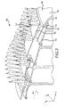
Figure 2 illustrates, in accordance with various embodiments, a partial cross-sectional view of a compressor portion of a gas turbine engine; and -
Figure 3 illustrates, in accordance with various embodiments, a partial cross-sectional view of a compressor portion of a gas turbine engine. - The detailed description of embodiments herein makes reference to the accompanying drawings, which show embodiments by way of illustration. While these embodiments are described in sufficient detail to enable those skilled in the art to practice the inventions, it should be understood that other embodiments may be realized and that logical and mechanical changes may be made without departing from the scope of the inventions. Thus, the detailed description herein is presented for purposes of illustration only and not for limitation. For example, any reference to singular includes plural embodiments, and any reference to more than one component or step may include a singular embodiment or step. Also, any reference to attached, fixed, connected or the like may include permanent, removable, temporary, partial, full and/or any other possible attachment option.
- As used herein, "aft" refers to the direction associated with the tail of an aircraft, or generally, to the direction of exhaust of the gas turbine. As used herein, "forward" and/or "fore" refers to the direction associated with the nose of an aircraft, or generally, to the direction of flight or motion.
- With reference to
Figure 1 , agas turbine engine 10 is shown. In general terms, gas turbine engine may comprise acompressor section 12. Air may flow throughcompressor section 12 and into acombustion chamber 14, where the air is mixed with a fuel source and may be ignited to produce hot combustion gasses. These hot combustion gasses may drive a series of turbine blades within aturbine section 16, which in turn drive, for example, one or more compressor section blades mechanically coupled thereto. - With reference to
Figures 2 and3 ,compressor section 12 may comprise ahigh pressure section 100.High pressure section 100 may comprise, for example, anaft rotor segment 102. In various embodiments,aft rotor segment 102 may comprise the furthest aft rotor segment in thehigh pressure section 100.High pressure section 100 may comprise, for example, a plurality of blade segments and spacer segments located fore ofaft rotor segment 102. In various embodiments,aft rotor segment 102 comprises a blade segment. In further embodiments,aft rotor segment 102 comprises a spacer segment. - In various embodiments,
aft rotor segment 102 comprises anouter rim 110 aninner rim 112.Aft rotor segment 102 may further comprise one ormore cooling channels 114. For example,cooling channels 114 may be disposed betweenouter rim 110 andinner rim 112 and provide cooler air to the rotor segments ofhigh pressure section 100. -
High pressure section 100 further comprises arear hub 104. In various embodiments,rear hub 104 is disposed aft ofaft rotor segment 102.Rear hub 104 may comprise anouter surface 106 and aninner surface 108. In various embodiments,rear hub 104 is adjacent and in contact withaft rotor segment 102. For example,rear hub 104 may be engaged withaft rotor segment 102 in a fluid-tight seal, such that air traversingouter rim 110 ofaft rotor segment 102 is prevented from mixing with air traversingcooling channels 114. - In various embodiments,
inner surface 108 is in fluid communication withcooling channels 114. For example, cooler air traversingcooling channels 114 may exitcooling channels 114, enterrear hub 104, and assist in coolinginner surface 108 ofrear hub 104. -
Rear hub 104 may further comprise, for example, a sealingface 120. For example, sealingface 120 may sealingly engage withaft rotor segment 102 to form a fluid-tight seal. In various embodiments, sealingface 120 comprises a flange, rim, or other feature. For example, sealingface 120 may comprise a flange having one or morehub inlet ports 122. In various embodiments,hub inlet ports 122 may be aligned withcooling channels 114 to allow air traversingcooling channels 114 to enterrear hub 104 at a desired pressure and angle. For example, sealingface 120 may comprise the same number ofhub inlet ports 122 ascooling channels 114 ofaft rotor segment 102. In such configurations, eachcooling channel 114 may be aligned with an individualhub inlet port 122. - In various embodiments, sealing
face 120 may comprise an outer radius that is equal to the outer radius ofouter rim 110 ofaft rotor segment 102. In further embodiments, the outer radius of sealingface 120 may be less than the radius ofouter rim 110. In such embodiments, a portion ofouter rim 110 may extend aft ofinner rim 112 ofaft rotor segment 102 and sealingface 120. Stated another way, a portion ofouter rim 110 may extend past and cover a portion ofouter surface 106 ofrear hub 104. - Rear hub may further comprise, for example, a
low pressure sink 124. In various embodiments, air traversingcooling channels 114 is directed along acooling path 126 to channel the flow tolow pressure sink 124 located withinrear hub 104. - Benefits, other advantages, and solutions to problems have been described herein with regard to specific embodiments. Furthermore, the connecting lines shown in the various figures contained herein are intended to represent functional relationships and/or physical couplings between the various elements. It should be noted that many alternative or additional functional relationships or physical connections may be present in a practical system. However, the benefits, advantages, solutions to problems, and any elements that may cause any benefit, advantage, or solution to occur or become more pronounced are not to be construed as critical, required, or essential features or elements of the inventions. The scope of the inventions is accordingly to be limited by nothing other than the appended claims, in which reference to an element in the singular is not intended to mean "one and only one" unless explicitly so stated, but rather "one or more." Moreover, where a phrase similar to "at least one of A, B, or C" is used in the claims, it is intended that the phrase be interpreted to mean that A alone may be present in an embodiment, B alone may be present in an embodiment, C alone may be present in an embodiment, or that any combination of the elements A, B and C may be present in a single embodiment; for example, A and B, A and C, B and C, or A and B and C. Different cross-hatching is used throughout the figures to denote different parts but not necessarily to denote the same or different materials.
- Systems, methods and apparatus are provided herein. In the detailed description herein, references to "one embodiment," "an embodiment," "an example embodiment," etc., indicate that the embodiment described may include a particular feature, structure, or characteristic, but every embodiment may not necessarily include the particular feature, structure, or characteristic. Moreover, such phrases are not necessarily referring to the same embodiment. Further, when a particular feature, structure, or characteristic is described in connection with an embodiment, it is submitted that it is within the knowledge of one skilled in the art to affect such feature, structure, or characteristic in connection with other embodiments whether or not explicitly described. After reading the description, it will be apparent to one skilled in the relevant art(s) how to implement the disclosure in alternative embodiments.
- Furthermore, no element, component, or method step in the present disclosure is intended to be dedicated to the public regardless of whether the element, component, or method step is explicitly recited in the claims. No claim element herein is to be construed under the provisions of 35 U.S.C. 112(f), unless the element is expressly recited using the phrase "means for." As used herein, the terms "comprises," "comprising," or any other variation thereof, are intended to cover a non-exclusive inclusion, such that a process, method, article, or apparatus that comprises a list of elements does not include only those elements but may include other elements not expressly listed or inherent to such process, method, article, or apparatus.
Claims (11)
- A gas turbine engine compressor comprising:an aft rotor segment (102) comprising an outer rim (110), an inner rim (112), and a cooling channel (114) disposed between the inner rim (112) and the outer rim (110); anda rear hub (104) disposed aft of the aft rotor segment (102) and comprising an inner surface (108), an outer surface (106), and a sealing face (120), wherein the sealing face (120) is sealingly engaged with the aft rotor segment (102), and wherein the inner surface (108) of the rear hub (104) is in fluid communication with the cooling channel (114).
- The gas turbine engine compressor of claim 1, wherein the sealing face (120) of the rear hub (104) is sealingly engaged with the outer rim (110) of the aft rotor segment (102).
- The gas turbine engine compressor of claim 1 or 2, wherein the cooling channel (114) is configured to delivery air to contact the inner surface (108) of the rear hub (104).
- The gas turbine engine compressor of any preceding, wherein the rear hub (104) further comprises a low pressure sink (124) and a cooling path (126), wherein the cooling path (126) directs air from the cooling channel (114) to the low pressure sink (124).
- The gas turbine engine compressor of any preceding claim, wherein an outer radius of the sealing face (120) is equal to or less than a radius of the outer rim (110).
- The gas turbine engine compressor of any preceding claim, wherein the sealing face (120) comprises a hub inlet port (122) that aligns and is in fluid communication with the cooling channel (114).
- The gas turbine engine compressor of any preceding claim, wherein the aft rotor segment (102) comprises a plurality of cooling channels (114).
- The gas turbine engine compressor of claim 7, wherein the sealing face (120) comprises the same number of hub inlet ports (122) as cooling channels (114), and each hub inlet port (122) is in fluid communication with a corresponding cooling channel (114).
- The gas turbine engine compressor of any preceding claim, wherein the sealing face (120) engages with the inner rim (112).
- The gas turbine engine compressor of any preceding claim, wherein a portion of the outer rim (110) extends aft of the sealing face (120) of the rear hub (104).
- A gas turbine engine (10) comprising:the gas turbine compressor of any preceding claim, said compressor being an axial high pressure compressor.
Applications Claiming Priority (1)
| Application Number | Priority Date | Filing Date | Title |
|---|---|---|---|
| US201462031614P | 2014-07-31 | 2014-07-31 |
Publications (2)
| Publication Number | Publication Date |
|---|---|
| EP2980356A1 true EP2980356A1 (en) | 2016-02-03 |
| EP2980356B1 EP2980356B1 (en) | 2020-01-22 |
Family
ID=53776388
Family Applications (1)
| Application Number | Title | Priority Date | Filing Date |
|---|---|---|---|
| EP15178888.2A Active EP2980356B1 (en) | 2014-07-31 | 2015-07-29 | Gas turbine engine axial compressor rear hub |
Country Status (2)
| Country | Link |
|---|---|
| US (1) | US9879537B2 (en) |
| EP (1) | EP2980356B1 (en) |
Cited By (1)
| Publication number | Priority date | Publication date | Assignee | Title |
|---|---|---|---|---|
| EP2985421A1 (en) * | 2014-08-12 | 2016-02-17 | United Technologies Corporation | Assembly, compressor and cooling system |
Citations (3)
| Publication number | Priority date | Publication date | Assignee | Title |
|---|---|---|---|---|
| FR900439A (en) * | 1941-09-09 | 1945-06-28 | Daimler Benz Ag | Air cooling for multi-stage compressor blade holders |
| US4795307A (en) * | 1986-02-28 | 1989-01-03 | Mtu Motoren- Und Turbinen-Union Munchen Gmbh | Method and apparatus for optimizing the vane clearance in a multi-stage axial flow compressor of a gas turbine |
| US20130108466A1 (en) * | 2011-10-28 | 2013-05-02 | Gabriel L. Suciu | Asymetrically slotted rotor for a gas turbine engine |
Family Cites Families (5)
| Publication number | Priority date | Publication date | Assignee | Title |
|---|---|---|---|---|
| US2858103A (en) * | 1956-03-26 | 1958-10-28 | Westinghouse Electric Corp | Gas turbine apparatus |
| KR100389990B1 (en) * | 1995-04-06 | 2003-11-17 | 가부시끼가이샤 히다치 세이사꾸쇼 | Gas turbine |
| US6393829B2 (en) * | 1996-11-29 | 2002-05-28 | Hitachi, Ltd. | Coolant recovery type gas turbine |
| JP3518447B2 (en) * | 1999-11-05 | 2004-04-12 | 株式会社日立製作所 | Gas turbine, gas turbine device, and refrigerant recovery method for gas turbine rotor blade |
| JP3361501B2 (en) * | 2000-03-02 | 2003-01-07 | 株式会社日立製作所 | Closed-circuit blade cooling turbine |
-
2015
- 2015-07-07 US US14/793,479 patent/US9879537B2/en active Active
- 2015-07-29 EP EP15178888.2A patent/EP2980356B1/en active Active
Patent Citations (3)
| Publication number | Priority date | Publication date | Assignee | Title |
|---|---|---|---|---|
| FR900439A (en) * | 1941-09-09 | 1945-06-28 | Daimler Benz Ag | Air cooling for multi-stage compressor blade holders |
| US4795307A (en) * | 1986-02-28 | 1989-01-03 | Mtu Motoren- Und Turbinen-Union Munchen Gmbh | Method and apparatus for optimizing the vane clearance in a multi-stage axial flow compressor of a gas turbine |
| US20130108466A1 (en) * | 2011-10-28 | 2013-05-02 | Gabriel L. Suciu | Asymetrically slotted rotor for a gas turbine engine |
Cited By (2)
| Publication number | Priority date | Publication date | Assignee | Title |
|---|---|---|---|---|
| EP2985421A1 (en) * | 2014-08-12 | 2016-02-17 | United Technologies Corporation | Assembly, compressor and cooling system |
| US9963972B2 (en) | 2014-08-12 | 2018-05-08 | United Technologies Corporation | Mixing plenum for spoked rotors |
Also Published As
| Publication number | Publication date |
|---|---|
| US20160032726A1 (en) | 2016-02-04 |
| EP2980356B1 (en) | 2020-01-22 |
| US9879537B2 (en) | 2018-01-30 |
Similar Documents
| Publication | Publication Date | Title |
|---|---|---|
| US10060351B2 (en) | De-icing device for a splitter nose of an axial turbine engine compressor | |
| EP3015696B1 (en) | Gas turbine engine comprising a propulsor and an offset gas generator | |
| CN108952823B (en) | Method and system for leading edge auxiliary blade | |
| EP3473811B1 (en) | Fan blade platform | |
| US10138752B2 (en) | Active HPC clearance control | |
| EP3284942B1 (en) | Direct drive aft fan engine | |
| EP3153661A1 (en) | Method and system for modulated turbine cooling | |
| JP5856711B2 (en) | Aircraft engine drive shaft compartment assembly and method of assembling an aircraft engine drive shaft compartment assembly | |
| EP3131817B1 (en) | Engine inlet configuration | |
| EP2930371B1 (en) | Turbomachine with a bleeding port | |
| JP6505074B2 (en) | Method and system for inline distributed propulsion | |
| US20170159449A1 (en) | Gas turbine engine with fillet film holes | |
| US9995173B2 (en) | Ducting platform cover plate | |
| US9988935B2 (en) | Gas turbine engine with axial compressor with internal cooling pathways | |
| US20160201608A1 (en) | Systems and methods controlling fan pressure ratios | |
| US9879537B2 (en) | Gas turbine engine axial compressor rear hub | |
| US20160130977A1 (en) | Turbine rotor segmented sideplates with anti-rotation | |
| US12018582B2 (en) | Turbine blade for an aircraft turbine engine, comprising a platform provided with a channel for primary flow rejection towards a purge cavity | |
| EP4610525A2 (en) | Ribbed seal element for aircraft powerplant | |
| EP2980358B1 (en) | Gas turbine engine with axial compressor having improved air sealing | |
| EP4579069A1 (en) | Bleeding core air from a turbine engine core flowpath | |
| EP4477860A1 (en) | System and method for turbine engine turbine component cooling | |
| US20250197013A1 (en) | Open rotor aircraft propulsion system with anti-icing system | |
| US12152506B2 (en) | Bleed passage arrangement for a gas turbine engine shroud | |
| US12546229B1 (en) | Gas turbine engine rotor stage with seal members |
Legal Events
| Date | Code | Title | Description |
|---|---|---|---|
| PUAI | Public reference made under article 153(3) epc to a published international application that has entered the european phase |
Free format text: ORIGINAL CODE: 0009012 |
|
| AK | Designated contracting states |
Kind code of ref document: A1 Designated state(s): AL AT BE BG CH CY CZ DE DK EE ES FI FR GB GR HR HU IE IS IT LI LT LU LV MC MK MT NL NO PL PT RO RS SE SI SK SM TR |
|
| AX | Request for extension of the european patent |
Extension state: BA ME |
|
| 17P | Request for examination filed |
Effective date: 20160803 |
|
| RBV | Designated contracting states (corrected) |
Designated state(s): AL AT BE BG CH CY CZ DE DK EE ES FI FR GB GR HR HU IE IS IT LI LT LU LV MC MK MT NL NO PL PT RO RS SE SI SK SM TR |
|
| RAP1 | Party data changed (applicant data changed or rights of an application transferred) |
Owner name: UNITED TECHNOLOGIES CORPORATION |
|
| STAA | Information on the status of an ep patent application or granted ep patent |
Free format text: STATUS: EXAMINATION IS IN PROGRESS |
|
| 17Q | First examination report despatched |
Effective date: 20190104 |
|
| GRAP | Despatch of communication of intention to grant a patent |
Free format text: ORIGINAL CODE: EPIDOSNIGR1 |
|
| STAA | Information on the status of an ep patent application or granted ep patent |
Free format text: STATUS: GRANT OF PATENT IS INTENDED |
|
| INTG | Intention to grant announced |
Effective date: 20190809 |
|
| GRAS | Grant fee paid |
Free format text: ORIGINAL CODE: EPIDOSNIGR3 |
|
| GRAA | (expected) grant |
Free format text: ORIGINAL CODE: 0009210 |
|
| STAA | Information on the status of an ep patent application or granted ep patent |
Free format text: STATUS: THE PATENT HAS BEEN GRANTED |
|
| AK | Designated contracting states |
Kind code of ref document: B1 Designated state(s): AL AT BE BG CH CY CZ DE DK EE ES FI FR GB GR HR HU IE IS IT LI LT LU LV MC MK MT NL NO PL PT RO RS SE SI SK SM TR |
|
| REG | Reference to a national code |
Ref country code: GB Ref legal event code: FG4D |
|
| REG | Reference to a national code |
Ref country code: CH Ref legal event code: EP |
|
| REG | Reference to a national code |
Ref country code: AT Ref legal event code: REF Ref document number: 1227028 Country of ref document: AT Kind code of ref document: T Effective date: 20200215 |
|
| REG | Reference to a national code |
Ref country code: IE Ref legal event code: FG4D |
|
| REG | Reference to a national code |
Ref country code: DE Ref legal event code: R096 Ref document number: 602015045887 Country of ref document: DE |
|
| REG | Reference to a national code |
Ref country code: NL Ref legal event code: MP Effective date: 20200122 |
|
| REG | Reference to a national code |
Ref country code: LT Ref legal event code: MG4D |
|
| PG25 | Lapsed in a contracting state [announced via postgrant information from national office to epo] |
Ref country code: NL Free format text: LAPSE BECAUSE OF FAILURE TO SUBMIT A TRANSLATION OF THE DESCRIPTION OR TO PAY THE FEE WITHIN THE PRESCRIBED TIME-LIMIT Effective date: 20200122 Ref country code: RS Free format text: LAPSE BECAUSE OF FAILURE TO SUBMIT A TRANSLATION OF THE DESCRIPTION OR TO PAY THE FEE WITHIN THE PRESCRIBED TIME-LIMIT Effective date: 20200122 Ref country code: FI Free format text: LAPSE BECAUSE OF FAILURE TO SUBMIT A TRANSLATION OF THE DESCRIPTION OR TO PAY THE FEE WITHIN THE PRESCRIBED TIME-LIMIT Effective date: 20200122 Ref country code: NO Free format text: LAPSE BECAUSE OF FAILURE TO SUBMIT A TRANSLATION OF THE DESCRIPTION OR TO PAY THE FEE WITHIN THE PRESCRIBED TIME-LIMIT Effective date: 20200422 Ref country code: PT Free format text: LAPSE BECAUSE OF FAILURE TO SUBMIT A TRANSLATION OF THE DESCRIPTION OR TO PAY THE FEE WITHIN THE PRESCRIBED TIME-LIMIT Effective date: 20200614 |
|
| PG25 | Lapsed in a contracting state [announced via postgrant information from national office to epo] |
Ref country code: GR Free format text: LAPSE BECAUSE OF FAILURE TO SUBMIT A TRANSLATION OF THE DESCRIPTION OR TO PAY THE FEE WITHIN THE PRESCRIBED TIME-LIMIT Effective date: 20200423 Ref country code: BG Free format text: LAPSE BECAUSE OF FAILURE TO SUBMIT A TRANSLATION OF THE DESCRIPTION OR TO PAY THE FEE WITHIN THE PRESCRIBED TIME-LIMIT Effective date: 20200422 Ref country code: IS Free format text: LAPSE BECAUSE OF FAILURE TO SUBMIT A TRANSLATION OF THE DESCRIPTION OR TO PAY THE FEE WITHIN THE PRESCRIBED TIME-LIMIT Effective date: 20200522 Ref country code: SE Free format text: LAPSE BECAUSE OF FAILURE TO SUBMIT A TRANSLATION OF THE DESCRIPTION OR TO PAY THE FEE WITHIN THE PRESCRIBED TIME-LIMIT Effective date: 20200122 Ref country code: LV Free format text: LAPSE BECAUSE OF FAILURE TO SUBMIT A TRANSLATION OF THE DESCRIPTION OR TO PAY THE FEE WITHIN THE PRESCRIBED TIME-LIMIT Effective date: 20200122 Ref country code: HR Free format text: LAPSE BECAUSE OF FAILURE TO SUBMIT A TRANSLATION OF THE DESCRIPTION OR TO PAY THE FEE WITHIN THE PRESCRIBED TIME-LIMIT Effective date: 20200122 |
|
| REG | Reference to a national code |
Ref country code: DE Ref legal event code: R097 Ref document number: 602015045887 Country of ref document: DE |
|
| PG25 | Lapsed in a contracting state [announced via postgrant information from national office to epo] |
Ref country code: SM Free format text: LAPSE BECAUSE OF FAILURE TO SUBMIT A TRANSLATION OF THE DESCRIPTION OR TO PAY THE FEE WITHIN THE PRESCRIBED TIME-LIMIT Effective date: 20200122 Ref country code: EE Free format text: LAPSE BECAUSE OF FAILURE TO SUBMIT A TRANSLATION OF THE DESCRIPTION OR TO PAY THE FEE WITHIN THE PRESCRIBED TIME-LIMIT Effective date: 20200122 Ref country code: DK Free format text: LAPSE BECAUSE OF FAILURE TO SUBMIT A TRANSLATION OF THE DESCRIPTION OR TO PAY THE FEE WITHIN THE PRESCRIBED TIME-LIMIT Effective date: 20200122 Ref country code: SK Free format text: LAPSE BECAUSE OF FAILURE TO SUBMIT A TRANSLATION OF THE DESCRIPTION OR TO PAY THE FEE WITHIN THE PRESCRIBED TIME-LIMIT Effective date: 20200122 Ref country code: RO Free format text: LAPSE BECAUSE OF FAILURE TO SUBMIT A TRANSLATION OF THE DESCRIPTION OR TO PAY THE FEE WITHIN THE PRESCRIBED TIME-LIMIT Effective date: 20200122 Ref country code: ES Free format text: LAPSE BECAUSE OF FAILURE TO SUBMIT A TRANSLATION OF THE DESCRIPTION OR TO PAY THE FEE WITHIN THE PRESCRIBED TIME-LIMIT Effective date: 20200122 Ref country code: CZ Free format text: LAPSE BECAUSE OF FAILURE TO SUBMIT A TRANSLATION OF THE DESCRIPTION OR TO PAY THE FEE WITHIN THE PRESCRIBED TIME-LIMIT Effective date: 20200122 Ref country code: LT Free format text: LAPSE BECAUSE OF FAILURE TO SUBMIT A TRANSLATION OF THE DESCRIPTION OR TO PAY THE FEE WITHIN THE PRESCRIBED TIME-LIMIT Effective date: 20200122 |
|
| REG | Reference to a national code |
Ref country code: AT Ref legal event code: MK05 Ref document number: 1227028 Country of ref document: AT Kind code of ref document: T Effective date: 20200122 |
|
| PLBE | No opposition filed within time limit |
Free format text: ORIGINAL CODE: 0009261 |
|
| STAA | Information on the status of an ep patent application or granted ep patent |
Free format text: STATUS: NO OPPOSITION FILED WITHIN TIME LIMIT |
|
| 26N | No opposition filed |
Effective date: 20201023 |
|
| PG25 | Lapsed in a contracting state [announced via postgrant information from national office to epo] |
Ref country code: IT Free format text: LAPSE BECAUSE OF FAILURE TO SUBMIT A TRANSLATION OF THE DESCRIPTION OR TO PAY THE FEE WITHIN THE PRESCRIBED TIME-LIMIT Effective date: 20200122 Ref country code: AT Free format text: LAPSE BECAUSE OF FAILURE TO SUBMIT A TRANSLATION OF THE DESCRIPTION OR TO PAY THE FEE WITHIN THE PRESCRIBED TIME-LIMIT Effective date: 20200122 |
|
| PG25 | Lapsed in a contracting state [announced via postgrant information from national office to epo] |
Ref country code: SI Free format text: LAPSE BECAUSE OF FAILURE TO SUBMIT A TRANSLATION OF THE DESCRIPTION OR TO PAY THE FEE WITHIN THE PRESCRIBED TIME-LIMIT Effective date: 20200122 Ref country code: MC Free format text: LAPSE BECAUSE OF FAILURE TO SUBMIT A TRANSLATION OF THE DESCRIPTION OR TO PAY THE FEE WITHIN THE PRESCRIBED TIME-LIMIT Effective date: 20200122 Ref country code: PL Free format text: LAPSE BECAUSE OF FAILURE TO SUBMIT A TRANSLATION OF THE DESCRIPTION OR TO PAY THE FEE WITHIN THE PRESCRIBED TIME-LIMIT Effective date: 20200122 |
|
| REG | Reference to a national code |
Ref country code: CH Ref legal event code: PL |
|
| REG | Reference to a national code |
Ref country code: BE Ref legal event code: MM Effective date: 20200731 |
|
| PG25 | Lapsed in a contracting state [announced via postgrant information from national office to epo] |
Ref country code: LI Free format text: LAPSE BECAUSE OF NON-PAYMENT OF DUE FEES Effective date: 20200731 Ref country code: LU Free format text: LAPSE BECAUSE OF NON-PAYMENT OF DUE FEES Effective date: 20200729 Ref country code: CH Free format text: LAPSE BECAUSE OF NON-PAYMENT OF DUE FEES Effective date: 20200731 |
|
| PG25 | Lapsed in a contracting state [announced via postgrant information from national office to epo] |
Ref country code: BE Free format text: LAPSE BECAUSE OF NON-PAYMENT OF DUE FEES Effective date: 20200731 |
|
| PG25 | Lapsed in a contracting state [announced via postgrant information from national office to epo] |
Ref country code: IE Free format text: LAPSE BECAUSE OF NON-PAYMENT OF DUE FEES Effective date: 20200729 |
|
| PG25 | Lapsed in a contracting state [announced via postgrant information from national office to epo] |
Ref country code: TR Free format text: LAPSE BECAUSE OF FAILURE TO SUBMIT A TRANSLATION OF THE DESCRIPTION OR TO PAY THE FEE WITHIN THE PRESCRIBED TIME-LIMIT Effective date: 20200122 Ref country code: MT Free format text: LAPSE BECAUSE OF FAILURE TO SUBMIT A TRANSLATION OF THE DESCRIPTION OR TO PAY THE FEE WITHIN THE PRESCRIBED TIME-LIMIT Effective date: 20200122 Ref country code: CY Free format text: LAPSE BECAUSE OF FAILURE TO SUBMIT A TRANSLATION OF THE DESCRIPTION OR TO PAY THE FEE WITHIN THE PRESCRIBED TIME-LIMIT Effective date: 20200122 |
|
| PG25 | Lapsed in a contracting state [announced via postgrant information from national office to epo] |
Ref country code: MK Free format text: LAPSE BECAUSE OF FAILURE TO SUBMIT A TRANSLATION OF THE DESCRIPTION OR TO PAY THE FEE WITHIN THE PRESCRIBED TIME-LIMIT Effective date: 20200122 Ref country code: AL Free format text: LAPSE BECAUSE OF FAILURE TO SUBMIT A TRANSLATION OF THE DESCRIPTION OR TO PAY THE FEE WITHIN THE PRESCRIBED TIME-LIMIT Effective date: 20200122 |
|
| REG | Reference to a national code |
Ref country code: DE Ref legal event code: R081 Ref document number: 602015045887 Country of ref document: DE Owner name: RAYTHEON TECHNOLOGIES CORPORATION (N.D.GES.D.S, US Free format text: FORMER OWNER: UNITED TECHNOLOGIES CORPORATION, FARMINGTON, CONN., US Ref country code: DE Ref legal event code: R081 Ref document number: 602015045887 Country of ref document: DE Owner name: RTX CORPORATION (N.D.GES.D. STAATES DELAWARE),, US Free format text: FORMER OWNER: UNITED TECHNOLOGIES CORPORATION, FARMINGTON, CONN., US |
|
| P01 | Opt-out of the competence of the unified patent court (upc) registered |
Effective date: 20230520 |
|
| PGFP | Annual fee paid to national office [announced via postgrant information from national office to epo] |
Ref country code: GB Payment date: 20250619 Year of fee payment: 11 |
|
| PGFP | Annual fee paid to national office [announced via postgrant information from national office to epo] |
Ref country code: FR Payment date: 20250620 Year of fee payment: 11 |
|
| PGFP | Annual fee paid to national office [announced via postgrant information from national office to epo] |
Ref country code: DE Payment date: 20250620 Year of fee payment: 11 |
|
| REG | Reference to a national code |
Ref country code: DE Ref legal event code: R081 Ref document number: 602015045887 Country of ref document: DE Owner name: RTX CORPORATION (N.D.GES.D. STAATES DELAWARE),, US Free format text: FORMER OWNER: RAYTHEON TECHNOLOGIES CORPORATION (N.D.GES.D.STAATES DELAWARE), ARLINGTON, VA, US |