EP2979940A1 - Vehicle brake fluid pressure control device - Google Patents
Vehicle brake fluid pressure control device Download PDFInfo
- Publication number
- EP2979940A1 EP2979940A1 EP14773448.7A EP14773448A EP2979940A1 EP 2979940 A1 EP2979940 A1 EP 2979940A1 EP 14773448 A EP14773448 A EP 14773448A EP 2979940 A1 EP2979940 A1 EP 2979940A1
- Authority
- EP
- European Patent Office
- Prior art keywords
- hydraulic pressure
- vehicle
- brake
- holdable
- control
- Prior art date
- Legal status (The legal status is an assumption and is not a legal conclusion. Google has not performed a legal analysis and makes no representation as to the accuracy of the status listed.)
- Granted
Links
Images




Classifications
-
- B—PERFORMING OPERATIONS; TRANSPORTING
- B60—VEHICLES IN GENERAL
- B60T—VEHICLE BRAKE CONTROL SYSTEMS OR PARTS THEREOF; BRAKE CONTROL SYSTEMS OR PARTS THEREOF, IN GENERAL; ARRANGEMENT OF BRAKING ELEMENTS ON VEHICLES IN GENERAL; PORTABLE DEVICES FOR PREVENTING UNWANTED MOVEMENT OF VEHICLES; VEHICLE MODIFICATIONS TO FACILITATE COOLING OF BRAKES
- B60T8/00—Arrangements for adjusting wheel-braking force to meet varying vehicular or ground-surface conditions, e.g. limiting or varying distribution of braking force
- B60T8/24—Arrangements for adjusting wheel-braking force to meet varying vehicular or ground-surface conditions, e.g. limiting or varying distribution of braking force responsive to vehicle inclination or change of direction, e.g. negotiating bends
- B60T8/245—Longitudinal vehicle inclination
-
- B—PERFORMING OPERATIONS; TRANSPORTING
- B60—VEHICLES IN GENERAL
- B60T—VEHICLE BRAKE CONTROL SYSTEMS OR PARTS THEREOF; BRAKE CONTROL SYSTEMS OR PARTS THEREOF, IN GENERAL; ARRANGEMENT OF BRAKING ELEMENTS ON VEHICLES IN GENERAL; PORTABLE DEVICES FOR PREVENTING UNWANTED MOVEMENT OF VEHICLES; VEHICLE MODIFICATIONS TO FACILITATE COOLING OF BRAKES
- B60T7/00—Brake-action initiating means
- B60T7/02—Brake-action initiating means for personal initiation
- B60T7/04—Brake-action initiating means for personal initiation foot actuated
- B60T7/042—Brake-action initiating means for personal initiation foot actuated by electrical means, e.g. using travel or force sensors
-
- B—PERFORMING OPERATIONS; TRANSPORTING
- B60—VEHICLES IN GENERAL
- B60T—VEHICLE BRAKE CONTROL SYSTEMS OR PARTS THEREOF; BRAKE CONTROL SYSTEMS OR PARTS THEREOF, IN GENERAL; ARRANGEMENT OF BRAKING ELEMENTS ON VEHICLES IN GENERAL; PORTABLE DEVICES FOR PREVENTING UNWANTED MOVEMENT OF VEHICLES; VEHICLE MODIFICATIONS TO FACILITATE COOLING OF BRAKES
- B60T13/00—Transmitting braking action from initiating means to ultimate brake actuator with power assistance or drive; Brake systems incorporating such transmitting means, e.g. air-pressure brake systems
- B60T13/10—Transmitting braking action from initiating means to ultimate brake actuator with power assistance or drive; Brake systems incorporating such transmitting means, e.g. air-pressure brake systems with fluid assistance, drive, or release
- B60T13/12—Transmitting braking action from initiating means to ultimate brake actuator with power assistance or drive; Brake systems incorporating such transmitting means, e.g. air-pressure brake systems with fluid assistance, drive, or release the fluid being liquid
- B60T13/14—Transmitting braking action from initiating means to ultimate brake actuator with power assistance or drive; Brake systems incorporating such transmitting means, e.g. air-pressure brake systems with fluid assistance, drive, or release the fluid being liquid using accumulators or reservoirs fed by pumps
- B60T13/142—Systems with master cylinder
- B60T13/145—Master cylinder integrated or hydraulically coupled with booster
- B60T13/146—Part of the system directly actuated by booster pressure
-
- B—PERFORMING OPERATIONS; TRANSPORTING
- B60—VEHICLES IN GENERAL
- B60T—VEHICLE BRAKE CONTROL SYSTEMS OR PARTS THEREOF; BRAKE CONTROL SYSTEMS OR PARTS THEREOF, IN GENERAL; ARRANGEMENT OF BRAKING ELEMENTS ON VEHICLES IN GENERAL; PORTABLE DEVICES FOR PREVENTING UNWANTED MOVEMENT OF VEHICLES; VEHICLE MODIFICATIONS TO FACILITATE COOLING OF BRAKES
- B60T13/00—Transmitting braking action from initiating means to ultimate brake actuator with power assistance or drive; Brake systems incorporating such transmitting means, e.g. air-pressure brake systems
- B60T13/10—Transmitting braking action from initiating means to ultimate brake actuator with power assistance or drive; Brake systems incorporating such transmitting means, e.g. air-pressure brake systems with fluid assistance, drive, or release
- B60T13/66—Electrical control in fluid-pressure brake systems
- B60T13/662—Electrical control in fluid-pressure brake systems characterised by specified functions of the control system components
-
- B—PERFORMING OPERATIONS; TRANSPORTING
- B60—VEHICLES IN GENERAL
- B60T—VEHICLE BRAKE CONTROL SYSTEMS OR PARTS THEREOF; BRAKE CONTROL SYSTEMS OR PARTS THEREOF, IN GENERAL; ARRANGEMENT OF BRAKING ELEMENTS ON VEHICLES IN GENERAL; PORTABLE DEVICES FOR PREVENTING UNWANTED MOVEMENT OF VEHICLES; VEHICLE MODIFICATIONS TO FACILITATE COOLING OF BRAKES
- B60T13/00—Transmitting braking action from initiating means to ultimate brake actuator with power assistance or drive; Brake systems incorporating such transmitting means, e.g. air-pressure brake systems
- B60T13/10—Transmitting braking action from initiating means to ultimate brake actuator with power assistance or drive; Brake systems incorporating such transmitting means, e.g. air-pressure brake systems with fluid assistance, drive, or release
- B60T13/66—Electrical control in fluid-pressure brake systems
- B60T13/68—Electrical control in fluid-pressure brake systems by electrically-controlled valves
- B60T13/686—Electrical control in fluid-pressure brake systems by electrically-controlled valves in hydraulic systems or parts thereof
-
- B—PERFORMING OPERATIONS; TRANSPORTING
- B60—VEHICLES IN GENERAL
- B60T—VEHICLE BRAKE CONTROL SYSTEMS OR PARTS THEREOF; BRAKE CONTROL SYSTEMS OR PARTS THEREOF, IN GENERAL; ARRANGEMENT OF BRAKING ELEMENTS ON VEHICLES IN GENERAL; PORTABLE DEVICES FOR PREVENTING UNWANTED MOVEMENT OF VEHICLES; VEHICLE MODIFICATIONS TO FACILITATE COOLING OF BRAKES
- B60T13/00—Transmitting braking action from initiating means to ultimate brake actuator with power assistance or drive; Brake systems incorporating such transmitting means, e.g. air-pressure brake systems
- B60T13/74—Transmitting braking action from initiating means to ultimate brake actuator with power assistance or drive; Brake systems incorporating such transmitting means, e.g. air-pressure brake systems with electrical assistance or drive
- B60T13/745—Transmitting braking action from initiating means to ultimate brake actuator with power assistance or drive; Brake systems incorporating such transmitting means, e.g. air-pressure brake systems with electrical assistance or drive acting on a hydraulic system, e.g. a master cylinder
-
- B—PERFORMING OPERATIONS; TRANSPORTING
- B60—VEHICLES IN GENERAL
- B60T—VEHICLE BRAKE CONTROL SYSTEMS OR PARTS THEREOF; BRAKE CONTROL SYSTEMS OR PARTS THEREOF, IN GENERAL; ARRANGEMENT OF BRAKING ELEMENTS ON VEHICLES IN GENERAL; PORTABLE DEVICES FOR PREVENTING UNWANTED MOVEMENT OF VEHICLES; VEHICLE MODIFICATIONS TO FACILITATE COOLING OF BRAKES
- B60T8/00—Arrangements for adjusting wheel-braking force to meet varying vehicular or ground-surface conditions, e.g. limiting or varying distribution of braking force
- B60T8/17—Using electrical or electronic regulation means to control braking
- B60T8/172—Determining control parameters used in the regulation, e.g. by calculations involving measured or detected parameters
-
- B—PERFORMING OPERATIONS; TRANSPORTING
- B60—VEHICLES IN GENERAL
- B60T—VEHICLE BRAKE CONTROL SYSTEMS OR PARTS THEREOF; BRAKE CONTROL SYSTEMS OR PARTS THEREOF, IN GENERAL; ARRANGEMENT OF BRAKING ELEMENTS ON VEHICLES IN GENERAL; PORTABLE DEVICES FOR PREVENTING UNWANTED MOVEMENT OF VEHICLES; VEHICLE MODIFICATIONS TO FACILITATE COOLING OF BRAKES
- B60T8/00—Arrangements for adjusting wheel-braking force to meet varying vehicular or ground-surface conditions, e.g. limiting or varying distribution of braking force
- B60T8/32—Arrangements for adjusting wheel-braking force to meet varying vehicular or ground-surface conditions, e.g. limiting or varying distribution of braking force responsive to a speed condition, e.g. acceleration or deceleration
- B60T8/34—Arrangements for adjusting wheel-braking force to meet varying vehicular or ground-surface conditions, e.g. limiting or varying distribution of braking force responsive to a speed condition, e.g. acceleration or deceleration having a fluid pressure regulator responsive to a speed condition
- B60T8/40—Arrangements for adjusting wheel-braking force to meet varying vehicular or ground-surface conditions, e.g. limiting or varying distribution of braking force responsive to a speed condition, e.g. acceleration or deceleration having a fluid pressure regulator responsive to a speed condition comprising an additional fluid circuit including fluid pressurising means for modifying the pressure of the braking fluid, e.g. including wheel driven pumps for detecting a speed condition, or pumps which are controlled by means independent of the braking system
- B60T8/4072—Systems in which a driver input signal is used as a control signal for the additional fluid circuit which is normally used for braking
- B60T8/4081—Systems with stroke simulating devices for driver input
Definitions
- the present invention relates to a vehicle brake hydraulic pressure control apparatus.
- a known vehicle brake hydraulic pressure control apparatus including driving force estimation means for estimating a drive torque transferred from an engine to the drive wheels of a vehicle, backward force estimation means for estimating a backward force acting on the vehicle based on a road surface gradient, and braking force addition means for adding a braking force balanced with the backward force to the wheels based on the deviation between the drive torque and the backward force estimated by the driving force estimation means and the backward force estimation means, as a vehicle brake hydraulic pressure control apparatus holding the brake hydraulic pressure so as to, for example, keep the halt state of the vehicle (see PATENT LITERATURE 1). Specifically, this technique sets the braking force so that the sum of the drive torque and the braking force equals the backward force.
- An object of the invention is to provide a vehicle brake hydraulic pressure control apparatus that can hold the halt state of the vehicle even if the drive torque changes during a halt.
- the present invention that solves the above problem is a vehicle brake hydraulic pressure control apparatus installed in a vehicle changing a drive torque transferred to a wheel during a halt, the apparatus including vehicle holding means for performing vehicle holding control that holds an actual brake hydraulic pressure applied to the wheel during a halt and storage means for storing a holdable hydraulic pressure capable of holding the halt state of the vehicle before and after the drive torque changes during a halt, in which when determining that the actual brake hydraulic pressure is less than the holdable hydraulic pressure stored in the storage means at a start of the vehicle holding control, the vehicle holding means increases the actual brake hydraulic pressure to the holdable hydraulic pressure and holds the holdable hydraulic pressure.
- the holdable hydraulic pressure can be set to a first hydraulic pressure that is constant regardless of the road surface gradient.
- control becomes easier as compared with the structure in which, for example, the holdable hydraulic pressure is increased as the value of the road surface gradient increases when the road surface gradient is an ascending gradient equal to or more than a predetermined value.
- the holdable hydraulic pressure when the road surface gradient is less than the predetermined value, can be set to a second hydraulic pressure that is lower than the first hydraulic pressure.
- the holdable hydraulic pressure is set to the second hydraulic pressure (lower value) when the road surface gradient is less than the predetermined value (that is, a substantially flat road or a descending gradient), a needless rise in the actual brake hydraulic pressure can be suppressed as compared with the structure in which the first hydraulic pressure (higher value) is used even in, for example, a substantially flat road or the like, thereby achieving a smooth start from a standstill.
- the vehicle holding means may set a target hydraulic pressure in the vehicle holding control to the holdable hydraulic pressure or another target hydraulic pressure calculated in the other brake control, whichever is higher.
- the target hydraulic pressure in the vehicle holding control is set to the holdable hydraulic pressure or another target hydraulic pressure calculated in the other brake control, whichever is higher, the halt state of the vehicle can be held reliably at a high hydraulic pressure.
- a brake system 1 shown in Fig. 1 to which a control apparatus 100 as a vehicle brake hydraulic pressure control apparatus according to the invention is applied is configured to include a by-wire type electric brake system (for normal use) that operates the brake by transferring an electric signal and a conventional hydraulic brake system (for fail-safe use) that operates the brake by transferring a hydraulic pressure as is generated by depressing a brake pedal BP.
- a by-wire type electric brake system for normal use
- a conventional hydraulic brake system for fail-safe use
- the brake system 1 is configured to include an input apparatus U1 to which, when an operation of the brake pedal BP by the driver is performed, the operation is input, a motor cylinder apparatus U2 that generates a brake hydraulic pressure according to the amount (also referred to below as a brake operation amount) of operation of the brake pedal BP or according to necessary control, and a hydraulic pressure control unit U3 that performs brake hydraulic pressure control for assisting stabilization of vehicle behavior.
- the input apparatus U1, the motor cylinder apparatus U2, and the hydraulic pressure control unit U3 are configured by two systems: a first system that controls a front-right wheel brake FR and a rear-left wheel brake RL and a second system that controls a front-left wheel brake FL and a rear-right wheel brake RR.
- a hydraulic pressure line formed by a pipe such as, for example, a hose or tube hose.
- a pipe such as, for example, a hose or tube hose.
- the input apparatus U1 and the motor cylinder apparatus U2 are electrically interconnected by a harness (not shown).
- the brake system 1 can be installed in various types of vehicles such as, for example, a vehicle driven only by an engine (internal combustion), a hybrid vehicle, an electric vehicle, and a fuel cell vehicle. However, the brake system 1 is installed in a hybrid vehicle in the embodiment.
- the hybrid vehicle according to the embodiment is configured to perform an idling stop in which, for example, the engine is stopped when the vehicle CR is at a halt. That is, the vehicle CR according to the embodiment is configured so that the drive torque (creep torque) changes during a halt.
- the vehicle CR reduces the driving torque as the brake operation amount increases to suppress concentration of electric loads on a part of the driving circuit of a driving motor by continuing to generate the drive torque (creep torque) using a driving motor during a halt.
- the brake system 1 includes a wheel speed sensor 91, a steering angle sensor 92, a lateral acceleration sensor 93, a front-rear acceleration sensor 94, an accelerator pedal stroke sensor 95 for detecting the stroke of an accelerator pedal AP, a brake pedal stroke sensor 96 for detecting the stroke of the brake pedal BP, and a motor rotation angle sensor 97 in appropriate positions of the vehicle CR, and the output values of these sensors are output to the control apparatus 100.
- the motor rotation angle sensor 97 is a sensor that detects the rotation angle of an electric motor 42 (see Fig. 2 ) driving the motor cylinder apparatus U2.
- the control apparatus 100 includes, for example, a CPU, a RAM, a ROM, and an input-output circuit, performs computation processes based on data or programs stored in the ROM, and controls the input apparatus U1, the motor cylinder apparatus U2, and the hydraulic pressure control unit U3 according to the output values of the respective sensors described above. This enables the control apparatus 100 to provide appropriate braking forces for wheels W by controlling the brake hydraulic pressures applied to wheel cylinders H of the wheel brakes FR, RL, FL, and RR.
- connection port 63a of the first system of the input apparatus U1 is connected to an output port 32a of the motor cylinder apparatus U2 and an input port 68a of the hydraulic pressure control unit U3 via pipes.
- a connection port 63b of the second system is connected to an output port 32b of the motor cylinder apparatus U2 and an input port 68b of the hydraulic pressure control unit U3 via pipes.
- the hydraulic pressure control unit U3 is provided with four output ports 69a to 69d and the wheel cylinders H of the wheel brakes FR, RL, FL, and RR are connected to the ports 69a to 69d, respectively.
- the input apparatus U1 includes a tandem type master cylinder 10 that can generate a hydraulic pressure according to an operation of the brake pedal BP by the driver, and a first reservoir 65 attached to the master cylinder 10.
- a first piston 12a and a second piston 12b are slidably disposed at a predetermined distance from each other in the axial direction of the cylinder tube 11.
- the first piston 12a is disposed close to the brake pedal BP and is coupled to the brake pedal BP via a push rod 12z.
- the second piston 12b is disposed in a position more distant from the brake pedal BP than the first piston 12a.
- first piston 12a and the second piston 12b On each of the outer periphery surfaces of the first piston 12a and the second piston 12b, a pair of piston gaskets 13a and 13b are attached at a distance from each other in the axial direction.
- the section of first piston 12a between the pair of piston gaskets 13a and 13b and the section of the second piston 12b between the pair of piston gaskets 13a and 13b have smaller diameters to form back chambers 14a and 14b, respectively.
- the back chambers 14a and 14b are connected to the first reservoir 65 via supply ports 17a and 17b, respectively.
- a first pressure chamber 15a is formed between the first piston 12a and the second piston 12b and the first pressure chamber 15a is connected to the first reservoir 65 via a relief port 18a.
- a second pressure chamber 15b is formed between the second piston 12b and a side end portion of the cylinder tube 11 and the second pressure chamber 15b is connected to the first reservoir 65 via a relief port 18b.
- the first pressure chamber 15a and the second pressure chamber 15b each generate a brake hydraulic pressure corresponding to the force applied to the brake pedal BP when the driver depresses the brake pedal BP.
- a spring 16a is provided between the first piston 12a and the second piston 12b and a spring 16b is provided between the second piston 12b and a side end portion of the cylinder tube 11. Accordingly, when the driver stops operating the brake pedal BP, the first pressure chamber 15a and the second pressure chamber 15b are returned to have appropriate volumes.
- output ports 19a and 19b that correspond to and communicate with the first pressure chamber 15a and the second pressure chamber 15b are formed, respectively, on the cylinder tube 11, and the output ports 19a and 19b are connected to the connection ports 63a and 63b of the input apparatus U1 via pipes.
- a normally open solenoid valve 61a On a pipe interconnecting an output port 19a of the master cylinder 10 and the connection port 63a of the input apparatus U1, a normally open solenoid valve 61a is provided. On a pipe connecting an output port 19b of the master cylinder 10 and the connection port 63b of the input apparatus U1, a normally open solenoid valve 61b is provided.
- a stroke simulator 20 is connected, via a normally closed solenoid valve 62, to a pipe (branch hydraulic pressure line 64) connecting the output port 19b of the master cylinder 10 and the normally open solenoid valve 61b.
- the normally open solenoid valves 61a and 61b in Fig. 2 are in a normal operation state (closed state) in which the solenoid valves are energized.
- the normally closed solenoid valve 62 in Fig. 2 is also in a normal operation state (open state) in which the solenoid valve is energized.
- the stroke simulator 20 generates the stroke of a brake and its reaction force during by-wire control and makes the driver feel as if a braking force were generated by a depression force.
- a piston 22 is provided in a cylinder 21 and a hydraulic pressure chamber 24 communicating with the branch hydraulic pressure line 64 via the normally closed solenoid valve 62 is formed on one side of the piston 22.
- the hydraulic pressure chamber 24 can absorb a brake fluid derived from the second pressure chamber 15b of the master cylinder 10.
- a first return spring 23a having a high spring constant and a second return spring 23b having a low spring constant are provided in series between the piston 22 and the side end portion of the cylinder 21, so that the increase gradient of a pedal reaction force is low in an initial stage of depression of the brake pedal BP and the increase gradient of a pedal reaction force is high in a late stage of depression. Accordingly, the pedal feeling of the brake pedal BP is similar to that of existing master cylinders.
- a first hydraulic pressure sensor Pm is provided in the hydraulic pressure line coupling the output port 19a of the master cylinder 10 to the normally open solenoid valve 61 a and a second hydraulic pressure sensor Pp is provided in the hydraulic pressure line coupling the normally open solenoid valve 61b to the connection port 63b.
- the first hydraulic pressure sensor Pm measures the hydraulic pressure of the normally open solenoid valve 61 a close to the master cylinder 10, which is closed during normal operation.
- the second hydraulic pressure sensor Pp measures the hydraulic pressure of the normally open solenoid valve 61b close to the connection port 63b (close to the hydraulic pressure control unit U3), which is closed during normal operation.
- the output values of these sensors are output to the control apparatus 100.
- the motor cylinder apparatus U2 includes an actuator mechanism 40 having the electric motor 42 and a cylinder mechanism 30 operated by the actuator mechanism 40.
- the actuator mechanism 40 has an actuator housing 41 and the actuator housing 41 houses a ball screw mechanism 43 including a screw shaft 43a and a nut 43b and a reduction gear train 44 transferring the rotation of the electric motor 42 to the nut 43b.
- the screw shaft 43a is linked to a first slave piston 35a, which will be described later.
- the cylinder mechanism 30 includes a cylinder body 31 and a second reservoir 66 attached to the cylinder body 31.
- the second reservoir 66 is connected to the first reservoir 65 via a pipe 65a.
- the first slave piston 35a and a second slave piston 35b are disposed slidably at a predetermined distance from each other in the axial direction of the cylinder body 31.
- the first slave piston 35a is disposed close to the ball screw mechanism 43 so as to abut against one end of the screw shaft 43a and be movable in a longitudinal direction of the cylinder body 31 integrally with the screw shaft 43a.
- the second slave piston 35b is disposed in a position more distant from the ball screw mechanism 43 than the first slave piston 35a.
- first slave piston 35a and the second slave piston 35b On each of the outer periphery surfaces of the first slave piston 35a and the second slave piston 35b, a pair of slave piston gaskets 39a and 39b are attached in a distance from each other in the axial direction.
- the section of first slave piston 35a between the pair of slave piston gaskets 39a and 39b and the section of the second slave piston 35b between the pair of slave piston gaskets 39a and 39b have smaller diameters to form first back chamber 37a and second back chamber 37b, respectively.
- the first back chamber 37a and the second back chamber 37b are connected to the second reservoir 66 via reservoir ports 33a and 33b, respectively.
- a first hydraulic pressure chamber 36a is formed between the first slave piston 35a and the second slave piston 35b and a second hydraulic pressure chamber 36b is formed between the second slave piston 35b and a side end portion of the cylinder body 31.
- the output ports 32a and 32b that correspond to and communicate with the first hydraulic pressure chamber 36a and the second hydraulic pressure chamber 36b are formed, respectively, on the cylinder body 31.
- the output ports 32a and 32b are connected to the connection ports 63a and 63b of the input apparatus U1 and the input ports 68a and 68b of the hydraulic pressure control unit U3, respectively.
- the first hydraulic pressure chamber 36a and the second hydraulic pressure chamber 36b generate a brake hydraulic pressure when the screw shaft 43a moves toward the first slave piston 35a by the operation of the electric motor 42, and the generated hydraulic pressure is supplied to the hydraulic pressure control unit U3 via the output ports 32a and 32b.
- a spring 34a is provided between the first slave piston 35a and the second slave piston 35b and a spring 34b is provided between the second slave piston 35b and a side end portion of the cylinder body 31. Accordingly, when the screw shaft 43a moves away from the first slave piston 35a by the action of the electric motor 42, the first hydraulic pressure chamber 36a and the second hydraulic pressure chamber 36b are returned to have appropriate volumes.
- a restriction link 38a for restricting the maximum stroke (maximum displacement distance) and the minimum stroke (minimum displacement distance) between the first slave piston 35a and the second slave piston 35b is provided between the first slave piston 35a and the second slave piston 35b.
- a stopper pin 38b for restricting the sliding range of the second slave piston 35b and preventing over-returning toward the first slave piston 35 is provided in the second slave piston 35b.
- the hydraulic pressure control unit U3 is a well-known hydraulic pressure control unit and includes a first hydraulic pressure system 50A that controls the wheel brakes FR and RL and a second hydraulic pressure system 50B that controls the wheel brakes FL and RR. Since the first hydraulic pressure system 50A and the second hydraulic pressure system 50B have a similar structure, only the first hydraulic pressure system 50A will be described here and the second hydraulic pressure system 50B will not be described.
- the first hydraulic pressure system 50A has a pressure regulator 51, which is a normally open proportional solenoid valve that can adjust the difference between the upstream and downstream hydraulic pressures depending on a current to be supplied, in a hydraulic pressure line connecting the input port 68a and the output ports 69a and 69b.
- a check valve 51a that allows only a flow toward the output ports 69a and 69b is provided in parallel with the pressure regulator 51.
- the hydraulic pressure line closer to the wheel brakes RL and FR than the pressure regulator 51 is branched midway and connected to the output port 69a and the output port 69b.
- An inlet valve 52 which is a normally open solenoid valve, is provided in each of the positions on the hydraulic pressure line corresponding to the output ports 69a and 69b.
- a check valve 52a that allows only a flow toward the pressure regulator 51 is provided in parallel with each of the inlet valves 52.
- a recirculation hydraulic pressure line 57 extends between the pressure regulator 51 and the inlet valve 52 via an outlet valve 53 including a normally closed solenoid valve.
- a reservoir 54 that temporality absorbs an excess brake fluid, a check valve 54a, a check valve 55a, a pump 55, and a check valve 55b are arranged sequentially from the outlet valve 53 side.
- the check valves 54a, 55a, and 55b are disposed so as to allow only flows toward the line between the pressure regulator 51 and the inlet valve 52.
- the pump 55 is driven by a motor M and provided to generate a pressure toward the line between the pressure regulator 51 and the inlet valve 52.
- An introduction hydraulic pressure line 58 interconnecting the input port 68a and the pressure regulator 51 is connected to the section between the check valve 54a and the check valve 55a in the recirculation hydraulic pressure line 57 by a suction hydraulic pressure line 59 via a suction valve 56.
- a third hydraulic pressure sensor Ph is provided only in the first hydraulic pressure system 50A.
- the output value of the third hydraulic pressure sensor Ph is output to the control apparatus 100.
- the solenoid valves are not energized normally and a brake hydraulic pressure introduced from the input port 68a passes through the pressure regulator 51 and the inlet valve 52, is output to the output ports 69a and 69b, and is given to the wheel cylinders H as is. Then, when the excess brake hydraulic pressure of the wheel cylinders H is decompressed to perform anti-locking braking control, the corresponding inlet valve 52 is closed and the corresponding outlet valve 53 is opened to pass the brake fluid to the reservoir 54 through the recirculation hydraulic pressure line 57, thereby draining the brake fluid in the wheel cylinders H.
- the suction valve 56 is opened and then the motor M is driven, so that brake fluid can be actively supplied to the wheel cylinders H by the pressurization force of the pump 55.
- the degree of pressurization of the wheel cylinders H can be adjusted by feeding an appropriate current through the pressure regulator 51.
- control apparatus 100 will be described in detail.
- the control apparatus 100 performs known by-wire type brake control, ABS (anti-lock brake system) control, and vehicle holding control that holds the actual brake hydraulic pressure applied to the wheels during a halt.
- ABS anti-lock brake system
- control apparatus 100 includes a vehicle stop determination section 110, a road surface gradient calculation section 120, a brake hold controller 130 as an example of the vehicle holding means, and a storage 140 as an example of the storage means.
- the vehicle halt determination section 110 has a known halt determination function and, when determining that the vehicle has halted, outputs a halt signal indicating the fact to the brake hold controller 130.
- the halt determination may be performed by determining whether, for example, the vehicle body speed calculated based on a signal from the wheel speed sensor 91 is equal to or less than a predetermined value.
- the road surface gradient calculation section 120 has a function of calculating a road surface gradient based on a signal from the front-rear acceleration sensor 94. Specifically, the road surface gradient calculation section 120 calculates a road surface gradient as a positive value when the front-rear acceleration applied to the vehicle in a halt state is an acceleration oriented to the rear (when the front of the vehicle is higher) and calculates a road surface gradient as a negative value when the front-rear acceleration is an acceleration oriented to the front (when the front of the vehicle is lower). Then, the road surface gradient calculation section 120 outputs the calculated road surface gradient to the brake hold controller 130. The road surface gradient calculation section 120 may be configured to use, as the road surface gradient, the value acquired by, for example, filtering the acceleration detected by the front-rear acceleration sensor 94.
- the storage 140 stores changes in the drive torque during a halt, specifically the holdable hydraulic pressure capable of holding the halt state of the vehicle before and after reduction in the drive torque due to an idle stop. More specifically, as shown in Fig. 5 , the holdable hydraulic pressure is set to a first hydraulic pressure P1, which is constant regardless of the road surface gradient, when the road surface gradient is an ascending gradient equal to or more than a predetermined value ⁇ 1. When the road surface gradient is less than the predetermined value ⁇ 1, the holdable hydraulic pressure is set to a second hydraulic pressure P2, which is less than the first hydraulic pressure P1 and constant regardless of the road surface gradient.
- the specific values of the hydraulic pressures P1 and P2 can be set appropriately based on an experiment or simulation.
- the brake hold controller 130 has a function of performing vehicle holding control that holds the actual brake hydraulic pressure applied to the wheels during a halt.
- the brake hold controller 130 also has a function of determining whether the actual brake hydraulic pressure is less than the holdable hydraulic pressure when starting vehicle holding control.
- the actual brake hydraulic pressure only needs to be estimated based on, for example, the hydraulic pressure detected by the third hydraulic pressure sensor Ph or the operation history of components of the hydraulic pressure control unit U3.
- the brake hold controller 130 sets the target hydraulic pressure in vehicle holding control to the holdable hydraulic pressure, increases the actual brake hydraulic pressure to the holdable hydraulic pressure by driving the electric motor 42, and holds the actual brake hydraulic pressure to the holdable hydraulic pressure by stopping the electric motor 42.
- the actual brake hydraulic pressure is less than the holdable hydraulic pressure considering a change in the drive torque at a start of vehicle holding control
- the actual brake hydraulic pressure is increased to the holdable hydraulic pressure, so the halt state of the vehicle can be held even when the drive torque is changed during a halt.
- the control apparatus 100 repeatedly executes the flowchart shown in Fig. 6 at all times.
- control apparatus 100 first acquires various parameters such as the wheel speed and front-rear acceleration from the sensors (S1). After step S1, the control apparatus 100 determines whether the vehicle is at a halt based on the wheel speed (S2).
- step S2 When determining that the vehicle does not stop in step S2 (No), the control apparatus 100 ends the control.
- the control apparatus 100 calculates the road surface gradient based on the front-rear acceleration (S3). After step S3, the control apparatus 100 determines whether the road surface gradient is equal to or more than the predetermined value ⁇ 1 (S4).
- step S4 When determining that the road surface gradient is equal to or more than the predetermined value ⁇ 1 in step S4 (Yes), the control apparatus 100 sets the target hydraulic pressure to the first hydraulic pressure P1 (S5). When determining that the road surface gradient is less than the predetermined value ⁇ 1 (No), the control apparatus 100 sets the target hydraulic pressure to the second hydraulic pressure P2 (S6). After step S5 or step S6, the control apparatus 100 determines whether the actual brake hydraulic pressure is equal to or more than the target hydraulic pressure, that is, the actual brake hydraulic pressure is equal to or more than the holdable hydraulic pressure (S7).
- step S7 when determining that the actual brake hydraulic pressure is less than target hydraulic pressure (No), the control apparatus 100 increases the actual brake hydraulic pressure by driving the electric motor 42 (S8) and returns to the process in step S7.
- step S7 when determining that the actual brake hydraulic pressure is equal to or more than target hydraulic pressure (Yes), the control apparatus 100 holds the actual brake hydraulic pressure at the target hydraulic pressure by stopping the electric motor 42 (S9) and ends the control.
- the actual brake hydraulic pressure held in step S9 is reduced by driving the electric motor 42 in a direction opposite to the direction in the case of pressurization when, for example, the driver depresses the accelerator pedal as in a known technique.
- the drive torque is a predetermined value T1 when the vehicle is at a halt on a road surface having a road surface gradient of the predetermined value ⁇ 1 or more (time t1), the drive torque gradually reduces if the engine is stopped by an idle stop.
- the control apparatus 100 starts vehicle holding control (time t1). If the actual brake hydraulic pressure is a hydraulic pressure P3, which is lower than the first hydraulic pressure P1 (holdable hydraulic pressure), when the vehicle is at a halt as shown in Fig. 7(b) , the control apparatus 100 sets the control mode of vehicle holding control to a pressurization mode (step S8 in Fig. 6 ) as shown in Fig. 7(a) to increase the actual brake hydraulic pressure. This can prevent the vehicle that has stopped once from sliding down due to reduction in the drive torque by increasing the actual brake hydraulic pressure.
- the control apparatus 100 sets the control mode to a holding mode to hold the actual brake hydraulic pressure at the first hydraulic pressure P1. Then, when detecting the depression of the accelerator pedal, the control apparatus 100 sets the control mode to a decompression mode (time t3), reduces the actual brake hydraulic pressure, and ends the vehicle holding control (time t4).
- the holdable hydraulic pressure is the first hydraulic pressure P1, which is a constant value, in the case of an ascending gradient having a road surface gradient of the predetermined value ⁇ 1 or more, control becomes easier than in the structure in which, for example, the holdable hydraulic pressure becomes larger with the value of the road surface gradient in the case of an ascending gradient having a road surface gradient equal to or more than the predetermined value.
- the holdable hydraulic pressure is set to the second hydraulic pressure P2 (lower value) when the road surface gradient is less than the predetermined value ⁇ 1 (that is, in the case of a substantially flat road or descending gradient), a needless rise in the actual brake hydraulic pressure can be suppressed as compared with the structure in which, for example, the first hydraulic value P1 (higher value) is used even in, for example, a substantially flat road or the like, thereby achieving a smooth start from a standstill.
- the invention is not limited to the embodiment and can be used in various embodiments as illustrated below.
- the vehicle holding control that holds the actual brake hydraulic pressure regardless of whether the road surface is a descending gradient, flat road, or ascending gradient has been described.
- the invention is not limited to the embodiment and it is possible to perform other brake control different from the vehicle holding control together with the vehicle holding control.
- the target hydraulic pressure in the vehicle holding control is preferably set to the holdable hydraulic pressure or another target hydraulic pressure calculated in the other brake control, whichever is higher.
- control apparatus In order to perform such control, the control apparatus only needs to be operated according to, for example, a flowchart as shown in Fig. 8 .
- new steps S11 and S 12 are added between step S5 and step S7 in the flowchart shown in Fig. 6 .
- step S11 the control apparatus determines whether another target hydraulic pressure is set by other brake control (for example, hill start assist control).
- the control apparatus sets a new target hydraulic pressure to the target hydraulic pressure (holdable hydraulic pressure) set in step S5 or step S6 or the other target hydraulic pressure, whichever is higher (S12) and proceeds to the process in step S7.
- the control apparatus proceeds to the process in step S7.
- the target hydraulic pressure in the vehicle holding control is set to the holdable hydraulic pressure or another target hydraulic pressure calculated in other brake control, whichever is higher, in this method, the halt state of the vehicle can be held reliably at a high hydraulic pressure.
- the invention is not limited to the embodiment and the hydraulic pressure may be increased by, for example, driving the motor M of the hydraulic control unit U3, the hydraulic pressure may be held by controlling the current passing through the pressure regulator 51, and the hydraulic pressure may be reduced by controlling the outlet valve 53.
- the brake system 1 is installed in a hybrid vehicle in the above embodiment, the invention is not limited to the embodiment and the brake system 1 may be installed in a vehicle or the like having an idle stop function other than hybrid vehicles.
Landscapes
- Engineering & Computer Science (AREA)
- Transportation (AREA)
- Mechanical Engineering (AREA)
- Physics & Mathematics (AREA)
- Fluid Mechanics (AREA)
- Regulating Braking Force (AREA)
Abstract
Description
- The present invention relates to a vehicle brake hydraulic pressure control apparatus.
- Conventionally, there is a known vehicle brake hydraulic pressure control apparatus including driving force estimation means for estimating a drive torque transferred from an engine to the drive wheels of a vehicle, backward force estimation means for estimating a backward force acting on the vehicle based on a road surface gradient, and braking force addition means for adding a braking force balanced with the backward force to the wheels based on the deviation between the drive torque and the backward force estimated by the driving force estimation means and the backward force estimation means, as a vehicle brake hydraulic pressure control apparatus holding the brake hydraulic pressure so as to, for example, keep the halt state of the vehicle (see PATENT LITERATURE 1). Specifically, this technique sets the braking force so that the sum of the drive torque and the braking force equals the backward force.
- PATENT LITERATURE 1:
JP-A-7-69102 - However, in a vehicle in which the drive torque is reduced at a halt by an idle stop or the like, it is difficult to accurately estimate the drive force that is being reduced, as needed. Accordingly, even when the vehicle is at a halt on an ascending slope with a predetermined drive torque applied, reduction in the drive torque produces a difference between the actual drive torque and the estimated drive torque, possibly causing the vehicle to slide down.
- An object of the invention is to provide a vehicle brake hydraulic pressure control apparatus that can hold the halt state of the vehicle even if the drive torque changes during a halt.
- The present invention that solves the above problem is a vehicle brake hydraulic pressure control apparatus installed in a vehicle changing a drive torque transferred to a wheel during a halt, the apparatus including vehicle holding means for performing vehicle holding control that holds an actual brake hydraulic pressure applied to the wheel during a halt and storage means for storing a holdable hydraulic pressure capable of holding the halt state of the vehicle before and after the drive torque changes during a halt, in which when determining that the actual brake hydraulic pressure is less than the holdable hydraulic pressure stored in the storage means at a start of the vehicle holding control, the vehicle holding means increases the actual brake hydraulic pressure to the holdable hydraulic pressure and holds the holdable hydraulic pressure.
- In this structure, when the actual brake hydraulic pressure is less than the holdable hydraulic pressure considering a change in the drive torque at a start of vehicle holding control, the actual brake hydraulic pressure is increased to the holdable hydraulic pressure, so the halt state of the vehicle can be held even when the drive torque is changed during a halt.
- In addition, in the above structure, when the vehicle is configured to reduce the drive torque as a brake operation amount increases, if at least a road surface gradient is an ascending gradient equal to or more than a predetermined value, the holdable hydraulic pressure can be set to a first hydraulic pressure that is constant regardless of the road surface gradient.
- In such a structure, when the road surface gradient is an ascending gradient equal to or more than a predetermined value, since the brake operation amount is increased when the driver depresses the brake strongly, the drive torque becomes a very small value (for example, 0). Accordingly, when the road surface gradient is an ascending gradient equal to or more than a predetermined value, effects of a change in the drive torque during a halt do not need to be considered. Therefore, even if the holdable hydraulic pressure is set to the first hydraulic pressure, which is a constant value, the halt state of the vehicle can be held. In the structure in which the holdable hydraulic pressure is set to the first hydraulic pressure when the road surface gradient is an ascending gradient equal to or more than a predetermined value as described above, control becomes easier as compared with the structure in which, for example, the holdable hydraulic pressure is increased as the value of the road surface gradient increases when the road surface gradient is an ascending gradient equal to or more than a predetermined value.
- In the above structure, when the road surface gradient is less than the predetermined value, the holdable hydraulic pressure can be set to a second hydraulic pressure that is lower than the first hydraulic pressure.
- In this case, since the holdable hydraulic pressure is set to the second hydraulic pressure (lower value) when the road surface gradient is less than the predetermined value (that is, a substantially flat road or a descending gradient), a needless rise in the actual brake hydraulic pressure can be suppressed as compared with the structure in which the first hydraulic pressure (higher value) is used even in, for example, a substantially flat road or the like, thereby achieving a smooth start from a standstill.
- In addition, in the above structure, when performing the vehicle holding control and other brake control different from the vehicle holding control at the same time, the vehicle holding means may set a target hydraulic pressure in the vehicle holding control to the holdable hydraulic pressure or another target hydraulic pressure calculated in the other brake control, whichever is higher.
- In this case, since the target hydraulic pressure in the vehicle holding control is set to the holdable hydraulic pressure or another target hydraulic pressure calculated in the other brake control, whichever is higher, the halt state of the vehicle can be held reliably at a high hydraulic pressure.
-
- [
Fig. 1] Fig. 1 is a structural diagram showing a vehicle including a control apparatus as an example of a vehicle brake hydraulic pressure control apparatus according to an embodiment of the present invention. - [
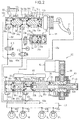
Fig. 2] Fig. 2 is a structural diagram showing brake hydraulic pressure circuits of an input apparatus and a motor cylinder apparatus. - [
Fig. 3] Fig. 3 is a structural diagram showing a brake hydraulic pressure circuit of a hydraulic pressure control unit. - [
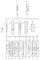
Fig. 4 ] Fig. is a block diagram showing the structure of the control apparatus. - [
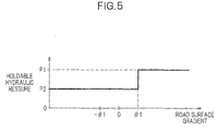
Fig. 5] Fig. 5 is a diagram showing the relationship between a holdable hydraulic pressure and a road surface gradient. - [
Fig. 6] Fig. 6 is a flowchart showing the operation of the control apparatus. - [
Fig. 7] Figs. 7 (a) to (c) show an example of changes in an actual brake hydraulic pressure and a drive torque in vehicle holding control. - [
Fig. 8] Fig. 8 is a flowchart showing the operation of a control apparatus according to a modification. - Next, an embodiment of the present invention will be described with reference to the drawings as appropriate.
- A
brake system 1 shown inFig. 1 to which acontrol apparatus 100 as a vehicle brake hydraulic pressure control apparatus according to the invention is applied is configured to include a by-wire type electric brake system (for normal use) that operates the brake by transferring an electric signal and a conventional hydraulic brake system (for fail-safe use) that operates the brake by transferring a hydraulic pressure as is generated by depressing a brake pedal BP. - Accordingly, the
brake system 1 is configured to include an input apparatus U1 to which, when an operation of the brake pedal BP by the driver is performed, the operation is input, a motor cylinder apparatus U2 that generates a brake hydraulic pressure according to the amount (also referred to below as a brake operation amount) of operation of the brake pedal BP or according to necessary control, and a hydraulic pressure control unit U3 that performs brake hydraulic pressure control for assisting stabilization of vehicle behavior. The input apparatus U1, the motor cylinder apparatus U2, and the hydraulic pressure control unit U3 are configured by two systems: a first system that controls a front-right wheel brake FR and a rear-left wheel brake RL and a second system that controls a front-left wheel brake FL and a rear-right wheel brake RR. For each system, an independent connection is made by a hydraulic pressure line formed by a pipe such as, for example, a hose or tube hose. In addition, the input apparatus U1 and the motor cylinder apparatus U2 are electrically interconnected by a harness (not shown). - The
brake system 1 can be installed in various types of vehicles such as, for example, a vehicle driven only by an engine (internal combustion), a hybrid vehicle, an electric vehicle, and a fuel cell vehicle. However, thebrake system 1 is installed in a hybrid vehicle in the embodiment. The hybrid vehicle according to the embodiment is configured to perform an idling stop in which, for example, the engine is stopped when the vehicle CR is at a halt. That is, the vehicle CR according to the embodiment is configured so that the drive torque (creep torque) changes during a halt. In addition, the vehicle CR according to the embodiment reduces the driving torque as the brake operation amount increases to suppress concentration of electric loads on a part of the driving circuit of a driving motor by continuing to generate the drive torque (creep torque) using a driving motor during a halt. - To control vehicle behavior using an electric brake system and the hydraulic pressure control unit U3, the
brake system 1 includes awheel speed sensor 91, asteering angle sensor 92, alateral acceleration sensor 93, a front-rear acceleration sensor 94, an acceleratorpedal stroke sensor 95 for detecting the stroke of an accelerator pedal AP, a brakepedal stroke sensor 96 for detecting the stroke of the brake pedal BP, and a motorrotation angle sensor 97 in appropriate positions of the vehicle CR, and the output values of these sensors are output to thecontrol apparatus 100. The motorrotation angle sensor 97 is a sensor that detects the rotation angle of an electric motor 42 (seeFig. 2 ) driving the motor cylinder apparatus U2. - The
control apparatus 100 includes, for example, a CPU, a RAM, a ROM, and an input-output circuit, performs computation processes based on data or programs stored in the ROM, and controls the input apparatus U1, the motor cylinder apparatus U2, and the hydraulic pressure control unit U3 according to the output values of the respective sensors described above. This enables thecontrol apparatus 100 to provide appropriate braking forces for wheels W by controlling the brake hydraulic pressures applied to wheel cylinders H of the wheel brakes FR, RL, FL, and RR. - As shown in
Fig. 2 , aconnection port 63a of the first system of the input apparatus U1 is connected to anoutput port 32a of the motor cylinder apparatus U2 and aninput port 68a of the hydraulic pressure control unit U3 via pipes. Similarly, aconnection port 63b of the second system is connected to anoutput port 32b of the motor cylinder apparatus U2 and aninput port 68b of the hydraulic pressure control unit U3 via pipes. - The hydraulic pressure control unit U3 is provided with four
output ports 69a to 69d and the wheel cylinders H of the wheel brakes FR, RL, FL, and RR are connected to theports 69a to 69d, respectively. - The input apparatus U1 includes a tandem
type master cylinder 10 that can generate a hydraulic pressure according to an operation of the brake pedal BP by the driver, and afirst reservoir 65 attached to themaster cylinder 10. In acylinder tube 11 of themaster cylinder 10, afirst piston 12a and a second piston 12b are slidably disposed at a predetermined distance from each other in the axial direction of thecylinder tube 11. Thefirst piston 12a is disposed close to the brake pedal BP and is coupled to the brake pedal BP via apush rod 12z. The second piston 12b is disposed in a position more distant from the brake pedal BP than thefirst piston 12a. - On each of the outer periphery surfaces of the
first piston 12a and the second piston 12b, a pair ofpiston gaskets first piston 12a between the pair ofpiston gaskets piston gaskets back chambers back chambers first reservoir 65 viasupply ports 17a and 17b, respectively. - A
first pressure chamber 15a is formed between thefirst piston 12a and the second piston 12b and thefirst pressure chamber 15a is connected to thefirst reservoir 65 via a relief port 18a. Similarly, asecond pressure chamber 15b is formed between the second piston 12b and a side end portion of thecylinder tube 11 and thesecond pressure chamber 15b is connected to thefirst reservoir 65 via arelief port 18b. Thefirst pressure chamber 15a and thesecond pressure chamber 15b each generate a brake hydraulic pressure corresponding to the force applied to the brake pedal BP when the driver depresses the brake pedal BP. - A
spring 16a is provided between thefirst piston 12a and the second piston 12b and a spring 16b is provided between the second piston 12b and a side end portion of thecylinder tube 11. Accordingly, when the driver stops operating the brake pedal BP, thefirst pressure chamber 15a and thesecond pressure chamber 15b are returned to have appropriate volumes. - In addition,
output ports 19a and 19b that correspond to and communicate with thefirst pressure chamber 15a and thesecond pressure chamber 15b are formed, respectively, on thecylinder tube 11, and theoutput ports 19a and 19b are connected to theconnection ports - On a pipe interconnecting an
output port 19a of themaster cylinder 10 and theconnection port 63a of the input apparatus U1, a normallyopen solenoid valve 61a is provided. On a pipe connecting an output port 19b of themaster cylinder 10 and theconnection port 63b of the input apparatus U1, a normallyopen solenoid valve 61b is provided. - A
stroke simulator 20 is connected, via a normally closedsolenoid valve 62, to a pipe (branch hydraulic pressure line 64) connecting the output port 19b of themaster cylinder 10 and the normallyopen solenoid valve 61b. - The normally
open solenoid valves Fig. 2 are in a normal operation state (closed state) in which the solenoid valves are energized. The normally closedsolenoid valve 62 inFig. 2 is also in a normal operation state (open state) in which the solenoid valve is energized. - The
stroke simulator 20 generates the stroke of a brake and its reaction force during by-wire control and makes the driver feel as if a braking force were generated by a depression force. Apiston 22 is provided in acylinder 21 and ahydraulic pressure chamber 24 communicating with the branchhydraulic pressure line 64 via the normally closedsolenoid valve 62 is formed on one side of thepiston 22. Thehydraulic pressure chamber 24 can absorb a brake fluid derived from thesecond pressure chamber 15b of themaster cylinder 10. - A
first return spring 23a having a high spring constant and asecond return spring 23b having a low spring constant are provided in series between thepiston 22 and the side end portion of thecylinder 21, so that the increase gradient of a pedal reaction force is low in an initial stage of depression of the brake pedal BP and the increase gradient of a pedal reaction force is high in a late stage of depression. Accordingly, the pedal feeling of the brake pedal BP is similar to that of existing master cylinders. - A first hydraulic pressure sensor Pm is provided in the hydraulic pressure line coupling the
output port 19a of themaster cylinder 10 to the normallyopen solenoid valve 61 a and a second hydraulic pressure sensor Pp is provided in the hydraulic pressure line coupling the normallyopen solenoid valve 61b to theconnection port 63b. The first hydraulic pressure sensor Pm measures the hydraulic pressure of the normallyopen solenoid valve 61 a close to themaster cylinder 10, which is closed during normal operation. The second hydraulic pressure sensor Pp measures the hydraulic pressure of the normallyopen solenoid valve 61b close to theconnection port 63b (close to the hydraulic pressure control unit U3), which is closed during normal operation. The output values of these sensors are output to thecontrol apparatus 100. - The motor cylinder apparatus U2 includes an
actuator mechanism 40 having theelectric motor 42 and acylinder mechanism 30 operated by theactuator mechanism 40. - The
actuator mechanism 40 has anactuator housing 41 and theactuator housing 41 houses aball screw mechanism 43 including a screw shaft 43a and anut 43b and areduction gear train 44 transferring the rotation of theelectric motor 42 to thenut 43b. The screw shaft 43a is linked to afirst slave piston 35a, which will be described later. - The
cylinder mechanism 30 includes acylinder body 31 and asecond reservoir 66 attached to thecylinder body 31. Thesecond reservoir 66 is connected to thefirst reservoir 65 via apipe 65a. In thecylinder body 31, thefirst slave piston 35a and asecond slave piston 35b are disposed slidably at a predetermined distance from each other in the axial direction of thecylinder body 31. Thefirst slave piston 35a is disposed close to theball screw mechanism 43 so as to abut against one end of the screw shaft 43a and be movable in a longitudinal direction of thecylinder body 31 integrally with the screw shaft 43a. Thesecond slave piston 35b is disposed in a position more distant from theball screw mechanism 43 than thefirst slave piston 35a. - On each of the outer periphery surfaces of the
first slave piston 35a and thesecond slave piston 35b, a pair ofslave piston gaskets first slave piston 35a between the pair ofslave piston gaskets second slave piston 35b between the pair ofslave piston gaskets first back chamber 37a andsecond back chamber 37b, respectively. Thefirst back chamber 37a and thesecond back chamber 37b are connected to thesecond reservoir 66 viareservoir ports 33a and 33b, respectively. - A first
hydraulic pressure chamber 36a is formed between thefirst slave piston 35a and thesecond slave piston 35b and a secondhydraulic pressure chamber 36b is formed between thesecond slave piston 35b and a side end portion of thecylinder body 31. Theoutput ports hydraulic pressure chamber 36a and the secondhydraulic pressure chamber 36b are formed, respectively, on thecylinder body 31. Theoutput ports connection ports input ports hydraulic pressure chamber 36a and the secondhydraulic pressure chamber 36b generate a brake hydraulic pressure when the screw shaft 43a moves toward thefirst slave piston 35a by the operation of theelectric motor 42, and the generated hydraulic pressure is supplied to the hydraulic pressure control unit U3 via theoutput ports - A spring 34a is provided between the
first slave piston 35a and thesecond slave piston 35b and aspring 34b is provided between thesecond slave piston 35b and a side end portion of thecylinder body 31. Accordingly, when the screw shaft 43a moves away from thefirst slave piston 35a by the action of theelectric motor 42, the firsthydraulic pressure chamber 36a and the secondhydraulic pressure chamber 36b are returned to have appropriate volumes. - A
restriction link 38a for restricting the maximum stroke (maximum displacement distance) and the minimum stroke (minimum displacement distance) between thefirst slave piston 35a and thesecond slave piston 35b is provided between thefirst slave piston 35a and thesecond slave piston 35b. Astopper pin 38b for restricting the sliding range of thesecond slave piston 35b and preventing over-returning toward the first slave piston 35 is provided in thesecond slave piston 35b. - As shown in
Fig. 3 , the hydraulic pressure control unit U3 is a well-known hydraulic pressure control unit and includes a firsthydraulic pressure system 50A that controls the wheel brakes FR and RL and a secondhydraulic pressure system 50B that controls the wheel brakes FL and RR. Since the firsthydraulic pressure system 50A and the secondhydraulic pressure system 50B have a similar structure, only the firsthydraulic pressure system 50A will be described here and the secondhydraulic pressure system 50B will not be described. - The first
hydraulic pressure system 50A has apressure regulator 51, which is a normally open proportional solenoid valve that can adjust the difference between the upstream and downstream hydraulic pressures depending on a current to be supplied, in a hydraulic pressure line connecting theinput port 68a and theoutput ports check valve 51a that allows only a flow toward theoutput ports pressure regulator 51. - The hydraulic pressure line closer to the wheel brakes RL and FR than the
pressure regulator 51 is branched midway and connected to theoutput port 69a and theoutput port 69b. Aninlet valve 52, which is a normally open solenoid valve, is provided in each of the positions on the hydraulic pressure line corresponding to theoutput ports check valve 52a that allows only a flow toward thepressure regulator 51 is provided in parallel with each of theinlet valves 52. - From the hydraulic pressure line between the
output port 69a and itscorresponding inlet valve 52 and the hydraulic pressure line between theoutput port 69b and itscorresponding inlet valve 52, a recirculationhydraulic pressure line 57 extends between thepressure regulator 51 and theinlet valve 52 via anoutlet valve 53 including a normally closed solenoid valve. - On the recirculation
hydraulic pressure line 57, areservoir 54 that temporality absorbs an excess brake fluid, acheck valve 54a, acheck valve 55a, apump 55, and acheck valve 55b are arranged sequentially from theoutlet valve 53 side. Thecheck valves pressure regulator 51 and theinlet valve 52. In addition, thepump 55 is driven by a motor M and provided to generate a pressure toward the line between thepressure regulator 51 and theinlet valve 52. - An introduction
hydraulic pressure line 58 interconnecting theinput port 68a and thepressure regulator 51 is connected to the section between thecheck valve 54a and thecheck valve 55a in the recirculationhydraulic pressure line 57 by a suctionhydraulic pressure line 59 via asuction valve 56. - In the introduction
hydraulic pressure line 58, a third hydraulic pressure sensor Ph is provided only in the firsthydraulic pressure system 50A. The output value of the third hydraulic pressure sensor Ph is output to thecontrol apparatus 100. - In the hydraulic pressure control unit U3 having the above structure, the solenoid valves are not energized normally and a brake hydraulic pressure introduced from the
input port 68a passes through thepressure regulator 51 and theinlet valve 52, is output to theoutput ports corresponding inlet valve 52 is closed and thecorresponding outlet valve 53 is opened to pass the brake fluid to thereservoir 54 through the recirculationhydraulic pressure line 57, thereby draining the brake fluid in the wheel cylinders H. When the wheel cylinders H are pressurized in the case where the driver does not operate the brake pedal BP, thesuction valve 56 is opened and then the motor M is driven, so that brake fluid can be actively supplied to the wheel cylinders H by the pressurization force of thepump 55. In addition, the degree of pressurization of the wheel cylinders H can be adjusted by feeding an appropriate current through thepressure regulator 51. - Next, the
control apparatus 100 will be described in detail. - As shown in
Fig. 4 , based on signals input from the sensors, thecontrol apparatus 100 performs known by-wire type brake control, ABS (anti-lock brake system) control, and vehicle holding control that holds the actual brake hydraulic pressure applied to the wheels during a halt. - Specifically, the
control apparatus 100 includes a vehiclestop determination section 110, a road surfacegradient calculation section 120, abrake hold controller 130 as an example of the vehicle holding means, and astorage 140 as an example of the storage means. - The vehicle
halt determination section 110 has a known halt determination function and, when determining that the vehicle has halted, outputs a halt signal indicating the fact to thebrake hold controller 130. The halt determination may be performed by determining whether, for example, the vehicle body speed calculated based on a signal from thewheel speed sensor 91 is equal to or less than a predetermined value. - The road surface
gradient calculation section 120 has a function of calculating a road surface gradient based on a signal from the front-rear acceleration sensor 94. Specifically, the road surfacegradient calculation section 120 calculates a road surface gradient as a positive value when the front-rear acceleration applied to the vehicle in a halt state is an acceleration oriented to the rear (when the front of the vehicle is higher) and calculates a road surface gradient as a negative value when the front-rear acceleration is an acceleration oriented to the front (when the front of the vehicle is lower). Then, the road surfacegradient calculation section 120 outputs the calculated road surface gradient to thebrake hold controller 130. The road surfacegradient calculation section 120 may be configured to use, as the road surface gradient, the value acquired by, for example, filtering the acceleration detected by the front-rear acceleration sensor 94. - The
storage 140 stores changes in the drive torque during a halt, specifically the holdable hydraulic pressure capable of holding the halt state of the vehicle before and after reduction in the drive torque due to an idle stop. More specifically, as shown inFig. 5 , the holdable hydraulic pressure is set to a first hydraulic pressure P1, which is constant regardless of the road surface gradient, when the road surface gradient is an ascending gradient equal to or more than a predetermined value θ1. When the road surface gradient is less than the predetermined value θ1, the holdable hydraulic pressure is set to a second hydraulic pressure P2, which is less than the first hydraulic pressure P1 and constant regardless of the road surface gradient. The specific values of the hydraulic pressures P1 and P2 can be set appropriately based on an experiment or simulation. - The
brake hold controller 130 has a function of performing vehicle holding control that holds the actual brake hydraulic pressure applied to the wheels during a halt. Thebrake hold controller 130 also has a function of determining whether the actual brake hydraulic pressure is less than the holdable hydraulic pressure when starting vehicle holding control. The actual brake hydraulic pressure only needs to be estimated based on, for example, the hydraulic pressure detected by the third hydraulic pressure sensor Ph or the operation history of components of the hydraulic pressure control unit U3. - When determining that the actual brake hydraulic pressure is less than the holdable hydraulic pressure, the
brake hold controller 130 sets the target hydraulic pressure in vehicle holding control to the holdable hydraulic pressure, increases the actual brake hydraulic pressure to the holdable hydraulic pressure by driving theelectric motor 42, and holds the actual brake hydraulic pressure to the holdable hydraulic pressure by stopping theelectric motor 42. - Accordingly, when the actual brake hydraulic pressure is less than the holdable hydraulic pressure considering a change in the drive torque at a start of vehicle holding control, the actual brake hydraulic pressure is increased to the holdable hydraulic pressure, so the halt state of the vehicle can be held even when the drive torque is changed during a halt.
- Next, the operation of the
control apparatus 100 will be described with reference toFig. 6 . - The
control apparatus 100 repeatedly executes the flowchart shown inFig. 6 at all times. - In this control, the
control apparatus 100 first acquires various parameters such as the wheel speed and front-rear acceleration from the sensors (S1). After step S1, thecontrol apparatus 100 determines whether the vehicle is at a halt based on the wheel speed (S2). - When determining that the vehicle does not stop in step S2 (No), the
control apparatus 100 ends the control. When determining that the vehicle is at a halt (Yes), thecontrol apparatus 100 calculates the road surface gradient based on the front-rear acceleration (S3). After step S3, thecontrol apparatus 100 determines whether the road surface gradient is equal to or more than the predetermined value θ1 (S4). - When determining that the road surface gradient is equal to or more than the predetermined value θ1 in step S4 (Yes), the
control apparatus 100 sets the target hydraulic pressure to the first hydraulic pressure P1 (S5). When determining that the road surface gradient is less than the predetermined value θ1 (No), thecontrol apparatus 100 sets the target hydraulic pressure to the second hydraulic pressure P2 (S6). After step S5 or step S6, thecontrol apparatus 100 determines whether the actual brake hydraulic pressure is equal to or more than the target hydraulic pressure, that is, the actual brake hydraulic pressure is equal to or more than the holdable hydraulic pressure (S7). - In step S7, when determining that the actual brake hydraulic pressure is less than target hydraulic pressure (No), the
control apparatus 100 increases the actual brake hydraulic pressure by driving the electric motor 42 (S8) and returns to the process in step S7. In step S7, when determining that the actual brake hydraulic pressure is equal to or more than target hydraulic pressure (Yes), thecontrol apparatus 100 holds the actual brake hydraulic pressure at the target hydraulic pressure by stopping the electric motor 42 (S9) and ends the control. The actual brake hydraulic pressure held in step S9 is reduced by driving theelectric motor 42 in a direction opposite to the direction in the case of pressurization when, for example, the driver depresses the accelerator pedal as in a known technique. - Next, an example of vehicle holding control by the
control apparatus 100 will be described in detail with reference toFig. 7 . Specifically, vehicle holding control when a vehicle is at a halt on a road surface having a road surface gradient of the predetermined value θ1 or more will be described. - As shown in
Fig. 7(c) , if the drive torque is a predetermined value T1 when the vehicle is at a halt on a road surface having a road surface gradient of the predetermined value θ1 or more (time t1), the drive torque gradually reduces if the engine is stopped by an idle stop. - On the other hand, as shown in
Fig. 7(a) , when the vehicle is at a halt, thecontrol apparatus 100 starts vehicle holding control (time t1). If the actual brake hydraulic pressure is a hydraulic pressure P3, which is lower than the first hydraulic pressure P1 (holdable hydraulic pressure), when the vehicle is at a halt as shown inFig. 7(b) , thecontrol apparatus 100 sets the control mode of vehicle holding control to a pressurization mode (step S8 inFig. 6 ) as shown inFig. 7(a) to increase the actual brake hydraulic pressure. This can prevent the vehicle that has stopped once from sliding down due to reduction in the drive torque by increasing the actual brake hydraulic pressure. - When the actual brake hydraulic pressure reaches the first hydraulic pressure P1 as shown in
Figs. 7(a) and 7(b) (time t2), thecontrol apparatus 100 sets the control mode to a holding mode to hold the actual brake hydraulic pressure at the first hydraulic pressure P1. Then, when detecting the depression of the accelerator pedal, thecontrol apparatus 100 sets the control mode to a decompression mode (time t3), reduces the actual brake hydraulic pressure, and ends the vehicle holding control (time t4). - According to the embodiment, the following effects can be obtained in addition to the above effects.
- Since the holdable hydraulic pressure is the first hydraulic pressure P1, which is a constant value, in the case of an ascending gradient having a road surface gradient of the predetermined value θ1 or more, control becomes easier than in the structure in which, for example, the holdable hydraulic pressure becomes larger with the value of the road surface gradient in the case of an ascending gradient having a road surface gradient equal to or more than the predetermined value. In a vehicle configured to reduce the drive torque with an increase in the brake operation amount as shown in the above embodiment, in the case of an ascending gradient having a road surface gradient of the predetermined value θ1 or more, since the brake operation amount is increased and the drive torque is reduced to a very small value (for example, 0) when the driver strongly depresses the brake to halt on the gradient, the drive torque is not significantly reduced from this value. Accordingly, when the road surface gradient is an ascending gradient having a road surface gradient equal to or more than the predetermined value θ1, effects of changes in the drive torque during a halt do not need to be considered. Accordingly, even if the holdable hydraulic pressure is set to the first hydraulic pressure P1, which is a constant value, the halt state of the vehicle can be held.
- Since the holdable hydraulic pressure is set to the second hydraulic pressure P2 (lower value) when the road surface gradient is less than the predetermined value θ1 (that is, in the case of a substantially flat road or descending gradient), a needless rise in the actual brake hydraulic pressure can be suppressed as compared with the structure in which, for example, the first hydraulic value P1 (higher value) is used even in, for example, a substantially flat road or the like, thereby achieving a smooth start from a standstill.
- The invention is not limited to the embodiment and can be used in various embodiments as illustrated below.
- In the above embodiment, only the vehicle holding control that holds the actual brake hydraulic pressure regardless of whether the road surface is a descending gradient, flat road, or ascending gradient has been described. However, the invention is not limited to the embodiment and it is possible to perform other brake control different from the vehicle holding control together with the vehicle holding control. In this case, the target hydraulic pressure in the vehicle holding control is preferably set to the holdable hydraulic pressure or another target hydraulic pressure calculated in the other brake control, whichever is higher.
- In order to perform such control, the control apparatus only needs to be operated according to, for example, a flowchart as shown in
Fig. 8 . In the flowchart shown inFig. 8 , new steps S11 andS 12 are added between step S5 and step S7 in the flowchart shown inFig. 6 . - In step S11, the control apparatus determines whether another target hydraulic pressure is set by other brake control (for example, hill start assist control). When determining that another target hydraulic pressure has been set (Yes) in step S11, the control apparatus sets a new target hydraulic pressure to the target hydraulic pressure (holdable hydraulic pressure) set in step S5 or step S6 or the other target hydraulic pressure, whichever is higher (S12) and proceeds to the process in step S7. When determining that another target hydraulic pressure is not set in step S11 (No), the control apparatus proceeds to the process in step S7.
- Since the target hydraulic pressure in the vehicle holding control is set to the holdable hydraulic pressure or another target hydraulic pressure calculated in other brake control, whichever is higher, in this method, the halt state of the vehicle can be held reliably at a high hydraulic pressure.
- Although the actual brake hydraulic pressure is increased, held, and reduced by controlling the
electric motor 42 in the above embodiment, the invention is not limited to the embodiment and the hydraulic pressure may be increased by, for example, driving the motor M of the hydraulic control unit U3, the hydraulic pressure may be held by controlling the current passing through thepressure regulator 51, and the hydraulic pressure may be reduced by controlling theoutlet valve 53. - Although the
brake system 1 is installed in a hybrid vehicle in the above embodiment, the invention is not limited to the embodiment and thebrake system 1 may be installed in a vehicle or the like having an idle stop function other than hybrid vehicles.
Claims (4)
- A vehicle brake hydraulic pressure control apparatus installed in a vehicle changing a drive torque transferred to a wheel during a halt, the apparatus comprising:vehicle holding means for performing vehicle holding control that holds an actual brake hydraulic pressure applied to the wheel during a halt; andstorage means for storing a holdable hydraulic pressure capable of holding a halt state of the vehicle before and after the drive torque changes during a halt;wherein, when determining that the actual brake hydraulic pressure is less than the holdable hydraulic pressure stored in the storage means at a start of the vehicle holding control, the vehicle holding means increases the actual brake hydraulic pressure to the holdable hydraulic pressure and holds the holdable hydraulic pressure.
- The vehicle brake hydraulic pressure control apparatus according to claim 1, wherein
the vehicle is configured to reduce the drive torque as a brake operation amount increases and
the holdable hydraulic pressure is set to a first hydraulic pressure that is constant regardless of the road surface gradient when at least a road surface gradient is an ascending gradient equal to or more than a predetermined value. - The vehicle brake hydraulic pressure control apparatus according to claim 2, wherein
the holdable hydraulic pressure is set to a second hydraulic pressure less than the first hydraulic pressure when the road surface gradient is less than the predetermined value. - The vehicle brake hydraulic pressure control apparatus according to any one of claims 1 to 3, wherein
when performing the vehicle holding control and other brake control different from the vehicle holding control at the same time, the vehicle holding means sets a target hydraulic pressure in the vehicle holding control to the holdable hydraulic pressure or another target hydraulic pressure calculated in the other brake control, whichever is higher.
Applications Claiming Priority (2)
| Application Number | Priority Date | Filing Date | Title |
|---|---|---|---|
| JP2013073316 | 2013-03-29 | ||
| PCT/JP2014/058219 WO2014157163A1 (en) | 2013-03-29 | 2014-03-25 | Vehicle brake fluid pressure control device |
Publications (3)
| Publication Number | Publication Date |
|---|---|
| EP2979940A1 true EP2979940A1 (en) | 2016-02-03 |
| EP2979940A4 EP2979940A4 (en) | 2016-07-27 |
| EP2979940B1 EP2979940B1 (en) | 2020-08-05 |
Family
ID=51624134
Family Applications (1)
| Application Number | Title | Priority Date | Filing Date |
|---|---|---|---|
| EP14773448.7A Active EP2979940B1 (en) | 2013-03-29 | 2014-03-25 | Vehicle brake fluid pressure control device |
Country Status (6)
| Country | Link |
|---|---|
| US (1) | US9610928B2 (en) |
| EP (1) | EP2979940B1 (en) |
| JP (1) | JP6358627B2 (en) |
| CN (1) | CN105073522B (en) |
| AU (1) | AU2014245884B2 (en) |
| WO (1) | WO2014157163A1 (en) |
Families Citing this family (4)
| Publication number | Priority date | Publication date | Assignee | Title |
|---|---|---|---|---|
| WO2014157162A1 (en) * | 2013-03-29 | 2014-10-02 | 日信工業株式会社 | Brake fluid pressure control device for vehicle |
| KR101766081B1 (en) * | 2015-12-09 | 2017-08-07 | 현대자동차주식회사 | Hill Start Assist Control Method for Vehicle |
| JP6694405B2 (en) * | 2017-03-17 | 2020-05-13 | 本田技研工業株式会社 | Control equipment for transportation equipment |
| US12196145B2 (en) * | 2023-05-31 | 2025-01-14 | Fca Us Llc | Engine speed management with increased electrical power supply |
Family Cites Families (13)
| Publication number | Priority date | Publication date | Assignee | Title |
|---|---|---|---|---|
| JPH0769102A (en) | 1993-09-03 | 1995-03-14 | Toyota Motor Corp | Slope stop device |
| JPH11334550A (en) * | 1998-05-21 | 1999-12-07 | Mitsubishi Electric Corp | Stop brake device |
| JP2007055536A (en) * | 2005-08-26 | 2007-03-08 | Toyota Motor Corp | Automobile and control method thereof |
| JP4858060B2 (en) * | 2006-10-03 | 2012-01-18 | 日産自動車株式会社 | Vehicle drive torque control device |
| JP4473894B2 (en) * | 2007-07-18 | 2010-06-02 | 日信工業株式会社 | Brake hydraulic pressure control device for vehicles |
| JP2009190648A (en) * | 2008-02-18 | 2009-08-27 | Hitachi Ltd | Brake control device |
| JP2010247788A (en) * | 2009-04-20 | 2010-11-04 | Toyota Motor Corp | Braking force control device |
| JP5177292B2 (en) * | 2009-07-13 | 2013-04-03 | トヨタ自動車株式会社 | Braking device control device and braking device |
| CN102844218B (en) * | 2010-05-17 | 2014-12-31 | 本田技研工业株式会社 | Control device and control method for electric vehicle |
| US9434364B2 (en) * | 2011-02-18 | 2016-09-06 | Advics Co., Ltd. | Braking control device for vehicle and braking control method for vehicle |
| JP2012046182A (en) * | 2011-10-12 | 2012-03-08 | Nissan Motor Co Ltd | Device for controlling idling stop of vehicle |
| JP5827198B2 (en) * | 2012-10-09 | 2015-12-02 | 日信工業株式会社 | Brake hydraulic pressure control device for vehicles |
| JP5632442B2 (en) * | 2012-11-20 | 2014-11-26 | 日信工業株式会社 | Brake hydraulic pressure control device for vehicles |
-
2014
- 2014-03-25 WO PCT/JP2014/058219 patent/WO2014157163A1/en not_active Ceased
- 2014-03-25 AU AU2014245884A patent/AU2014245884B2/en not_active Ceased
- 2014-03-25 JP JP2015508527A patent/JP6358627B2/en active Active
- 2014-03-25 EP EP14773448.7A patent/EP2979940B1/en active Active
- 2014-03-25 CN CN201480018786.8A patent/CN105073522B/en active Active
-
2015
- 2015-09-22 US US14/861,523 patent/US9610928B2/en active Active
Also Published As
| Publication number | Publication date |
|---|---|
| US20160075316A1 (en) | 2016-03-17 |
| EP2979940A4 (en) | 2016-07-27 |
| AU2014245884A1 (en) | 2015-08-20 |
| JP6358627B2 (en) | 2018-07-18 |
| WO2014157163A1 (en) | 2014-10-02 |
| AU2014245884B2 (en) | 2016-06-23 |
| CN105073522A (en) | 2015-11-18 |
| CN105073522B (en) | 2017-09-22 |
| US9610928B2 (en) | 2017-04-04 |
| JPWO2014157163A1 (en) | 2017-02-16 |
| EP2979940B1 (en) | 2020-08-05 |
Similar Documents
| Publication | Publication Date | Title |
|---|---|---|
| US9707945B2 (en) | Vehicle brake control apparatus | |
| JP5884245B2 (en) | Brake hydraulic pressure control device for vehicles | |
| JP5798153B2 (en) | Brake hydraulic pressure control device for vehicles | |
| JP6544335B2 (en) | Vehicle braking system | |
| US9610928B2 (en) | Vehicle brake hydraulic pressure control apparatus | |
| US9932024B2 (en) | Vehicle brake hydraulic pressure control apparatus | |
| US8915555B2 (en) | Brake control device for vehicle | |
| CN103832422A (en) | Vehicle brake hydraulic pressure control apparatus | |
| CN115335266B (en) | Braking device for vehicles | |
| JP3955208B2 (en) | Braking pressure estimation device | |
| WO2016175114A1 (en) | Braking device for vehicles | |
| JP6338047B2 (en) | Brake system | |
| JP6161363B2 (en) | Brake hydraulic pressure control device for vehicles | |
| JP2012162241A (en) | Braking power control system |
Legal Events
| Date | Code | Title | Description |
|---|---|---|---|
| PUAI | Public reference made under article 153(3) epc to a published international application that has entered the european phase |
Free format text: ORIGINAL CODE: 0009012 |
|
| 17P | Request for examination filed |
Effective date: 20151007 |
|
| AK | Designated contracting states |
Kind code of ref document: A1 Designated state(s): AL AT BE BG CH CY CZ DE DK EE ES FI FR GB GR HR HU IE IS IT LI LT LU LV MC MK MT NL NO PL PT RO RS SE SI SK SM TR |
|
| AX | Request for extension of the european patent |
Extension state: BA ME |
|
| DAX | Request for extension of the european patent (deleted) | ||
| A4 | Supplementary search report drawn up and despatched |
Effective date: 20160628 |
|
| RIC1 | Information provided on ipc code assigned before grant |
Ipc: B60T 7/12 20060101AFI20160622BHEP |
|
| RAP1 | Party data changed (applicant data changed or rights of an application transferred) |
Owner name: HONDA MOTOR CO., LTD. Owner name: AUTOLIV NISSIN BRAKE SYSTEMS JAPAN CO., LTD. |
|
| STAA | Information on the status of an ep patent application or granted ep patent |
Free format text: STATUS: EXAMINATION IS IN PROGRESS |
|
| 17Q | First examination report despatched |
Effective date: 20180731 |
|
| GRAP | Despatch of communication of intention to grant a patent |
Free format text: ORIGINAL CODE: EPIDOSNIGR1 |
|
| STAA | Information on the status of an ep patent application or granted ep patent |
Free format text: STATUS: GRANT OF PATENT IS INTENDED |
|
| INTG | Intention to grant announced |
Effective date: 20200218 |
|
| GRAS | Grant fee paid |
Free format text: ORIGINAL CODE: EPIDOSNIGR3 |
|
| GRAA | (expected) grant |
Free format text: ORIGINAL CODE: 0009210 |
|
| STAA | Information on the status of an ep patent application or granted ep patent |
Free format text: STATUS: THE PATENT HAS BEEN GRANTED |
|
| AK | Designated contracting states |
Kind code of ref document: B1 Designated state(s): AL AT BE BG CH CY CZ DE DK EE ES FI FR GB GR HR HU IE IS IT LI LT LU LV MC MK MT NL NO PL PT RO RS SE SI SK SM TR |
|
| REG | Reference to a national code |
Ref country code: GB Ref legal event code: FG4D |
|
| REG | Reference to a national code |
Ref country code: CH Ref legal event code: EP |
|
| REG | Reference to a national code |
Ref country code: AT Ref legal event code: REF Ref document number: 1298305 Country of ref document: AT Kind code of ref document: T Effective date: 20200815 |
|
| REG | Reference to a national code |
Ref country code: DE Ref legal event code: R096 Ref document number: 602014068612 Country of ref document: DE |
|
| REG | Reference to a national code |
Ref country code: IE Ref legal event code: FG4D |
|
| REG | Reference to a national code |
Ref country code: LT Ref legal event code: MG4D |
|
| REG | Reference to a national code |
Ref country code: NL Ref legal event code: MP Effective date: 20200805 |
|
| REG | Reference to a national code |
Ref country code: AT Ref legal event code: MK05 Ref document number: 1298305 Country of ref document: AT Kind code of ref document: T Effective date: 20200805 |
|
| PG25 | Lapsed in a contracting state [announced via postgrant information from national office to epo] |
Ref country code: ES Free format text: LAPSE BECAUSE OF FAILURE TO SUBMIT A TRANSLATION OF THE DESCRIPTION OR TO PAY THE FEE WITHIN THE PRESCRIBED TIME-LIMIT Effective date: 20200805 Ref country code: GR Free format text: LAPSE BECAUSE OF FAILURE TO SUBMIT A TRANSLATION OF THE DESCRIPTION OR TO PAY THE FEE WITHIN THE PRESCRIBED TIME-LIMIT Effective date: 20201106 Ref country code: PT Free format text: LAPSE BECAUSE OF FAILURE TO SUBMIT A TRANSLATION OF THE DESCRIPTION OR TO PAY THE FEE WITHIN THE PRESCRIBED TIME-LIMIT Effective date: 20201207 Ref country code: NO Free format text: LAPSE BECAUSE OF FAILURE TO SUBMIT A TRANSLATION OF THE DESCRIPTION OR TO PAY THE FEE WITHIN THE PRESCRIBED TIME-LIMIT Effective date: 20201105 Ref country code: BG Free format text: LAPSE BECAUSE OF FAILURE TO SUBMIT A TRANSLATION OF THE DESCRIPTION OR TO PAY THE FEE WITHIN THE PRESCRIBED TIME-LIMIT Effective date: 20201105 Ref country code: HR Free format text: LAPSE BECAUSE OF FAILURE TO SUBMIT A TRANSLATION OF THE DESCRIPTION OR TO PAY THE FEE WITHIN THE PRESCRIBED TIME-LIMIT Effective date: 20200805 Ref country code: SE Free format text: LAPSE BECAUSE OF FAILURE TO SUBMIT A TRANSLATION OF THE DESCRIPTION OR TO PAY THE FEE WITHIN THE PRESCRIBED TIME-LIMIT Effective date: 20200805 Ref country code: FI Free format text: LAPSE BECAUSE OF FAILURE TO SUBMIT A TRANSLATION OF THE DESCRIPTION OR TO PAY THE FEE WITHIN THE PRESCRIBED TIME-LIMIT Effective date: 20200805 Ref country code: LT Free format text: LAPSE BECAUSE OF FAILURE TO SUBMIT A TRANSLATION OF THE DESCRIPTION OR TO PAY THE FEE WITHIN THE PRESCRIBED TIME-LIMIT Effective date: 20200805 Ref country code: AT Free format text: LAPSE BECAUSE OF FAILURE TO SUBMIT A TRANSLATION OF THE DESCRIPTION OR TO PAY THE FEE WITHIN THE PRESCRIBED TIME-LIMIT Effective date: 20200805 |
|
| PG25 | Lapsed in a contracting state [announced via postgrant information from national office to epo] |
Ref country code: NL Free format text: LAPSE BECAUSE OF FAILURE TO SUBMIT A TRANSLATION OF THE DESCRIPTION OR TO PAY THE FEE WITHIN THE PRESCRIBED TIME-LIMIT Effective date: 20200805 Ref country code: PL Free format text: LAPSE BECAUSE OF FAILURE TO SUBMIT A TRANSLATION OF THE DESCRIPTION OR TO PAY THE FEE WITHIN THE PRESCRIBED TIME-LIMIT Effective date: 20200805 Ref country code: RS Free format text: LAPSE BECAUSE OF FAILURE TO SUBMIT A TRANSLATION OF THE DESCRIPTION OR TO PAY THE FEE WITHIN THE PRESCRIBED TIME-LIMIT Effective date: 20200805 Ref country code: LV Free format text: LAPSE BECAUSE OF FAILURE TO SUBMIT A TRANSLATION OF THE DESCRIPTION OR TO PAY THE FEE WITHIN THE PRESCRIBED TIME-LIMIT Effective date: 20200805 Ref country code: IS Free format text: LAPSE BECAUSE OF FAILURE TO SUBMIT A TRANSLATION OF THE DESCRIPTION OR TO PAY THE FEE WITHIN THE PRESCRIBED TIME-LIMIT Effective date: 20201205 |
|
| PG25 | Lapsed in a contracting state [announced via postgrant information from national office to epo] |
Ref country code: EE Free format text: LAPSE BECAUSE OF FAILURE TO SUBMIT A TRANSLATION OF THE DESCRIPTION OR TO PAY THE FEE WITHIN THE PRESCRIBED TIME-LIMIT Effective date: 20200805 Ref country code: CZ Free format text: LAPSE BECAUSE OF FAILURE TO SUBMIT A TRANSLATION OF THE DESCRIPTION OR TO PAY THE FEE WITHIN THE PRESCRIBED TIME-LIMIT Effective date: 20200805 Ref country code: DK Free format text: LAPSE BECAUSE OF FAILURE TO SUBMIT A TRANSLATION OF THE DESCRIPTION OR TO PAY THE FEE WITHIN THE PRESCRIBED TIME-LIMIT Effective date: 20200805 Ref country code: SM Free format text: LAPSE BECAUSE OF FAILURE TO SUBMIT A TRANSLATION OF THE DESCRIPTION OR TO PAY THE FEE WITHIN THE PRESCRIBED TIME-LIMIT Effective date: 20200805 Ref country code: RO Free format text: LAPSE BECAUSE OF FAILURE TO SUBMIT A TRANSLATION OF THE DESCRIPTION OR TO PAY THE FEE WITHIN THE PRESCRIBED TIME-LIMIT Effective date: 20200805 |
|
| REG | Reference to a national code |
Ref country code: DE Ref legal event code: R097 Ref document number: 602014068612 Country of ref document: DE |
|
| PG25 | Lapsed in a contracting state [announced via postgrant information from national office to epo] |
Ref country code: AL Free format text: LAPSE BECAUSE OF FAILURE TO SUBMIT A TRANSLATION OF THE DESCRIPTION OR TO PAY THE FEE WITHIN THE PRESCRIBED TIME-LIMIT Effective date: 20200805 |
|
| PLBE | No opposition filed within time limit |
Free format text: ORIGINAL CODE: 0009261 |
|
| STAA | Information on the status of an ep patent application or granted ep patent |
Free format text: STATUS: NO OPPOSITION FILED WITHIN TIME LIMIT |
|
| PG25 | Lapsed in a contracting state [announced via postgrant information from national office to epo] |
Ref country code: SK Free format text: LAPSE BECAUSE OF FAILURE TO SUBMIT A TRANSLATION OF THE DESCRIPTION OR TO PAY THE FEE WITHIN THE PRESCRIBED TIME-LIMIT Effective date: 20200805 |
|
| 26N | No opposition filed |
Effective date: 20210507 |
|
| PG25 | Lapsed in a contracting state [announced via postgrant information from national office to epo] |
Ref country code: IT Free format text: LAPSE BECAUSE OF FAILURE TO SUBMIT A TRANSLATION OF THE DESCRIPTION OR TO PAY THE FEE WITHIN THE PRESCRIBED TIME-LIMIT Effective date: 20200805 |
|
| PG25 | Lapsed in a contracting state [announced via postgrant information from national office to epo] |
Ref country code: SI Free format text: LAPSE BECAUSE OF FAILURE TO SUBMIT A TRANSLATION OF THE DESCRIPTION OR TO PAY THE FEE WITHIN THE PRESCRIBED TIME-LIMIT Effective date: 20200805 |
|
| PG25 | Lapsed in a contracting state [announced via postgrant information from national office to epo] |
Ref country code: MC Free format text: LAPSE BECAUSE OF FAILURE TO SUBMIT A TRANSLATION OF THE DESCRIPTION OR TO PAY THE FEE WITHIN THE PRESCRIBED TIME-LIMIT Effective date: 20200805 |
|
| REG | Reference to a national code |
Ref country code: CH Ref legal event code: PL |
|
| REG | Reference to a national code |
Ref country code: BE Ref legal event code: MM Effective date: 20210331 |
|
| PG25 | Lapsed in a contracting state [announced via postgrant information from national office to epo] |
Ref country code: LI Free format text: LAPSE BECAUSE OF NON-PAYMENT OF DUE FEES Effective date: 20210331 Ref country code: LU Free format text: LAPSE BECAUSE OF NON-PAYMENT OF DUE FEES Effective date: 20210325 Ref country code: CH Free format text: LAPSE BECAUSE OF NON-PAYMENT OF DUE FEES Effective date: 20210331 Ref country code: IE Free format text: LAPSE BECAUSE OF NON-PAYMENT OF DUE FEES Effective date: 20210325 Ref country code: FR Free format text: LAPSE BECAUSE OF NON-PAYMENT OF DUE FEES Effective date: 20210331 |
|
| REG | Reference to a national code |
Ref country code: DE Ref legal event code: R081 Ref document number: 602014068612 Country of ref document: DE Owner name: HONDA MOTOR CO., LTD., JP Free format text: FORMER OWNERS: AUTOLIV NISSIN BRAKE SYSTEMS JAPAN CO., LTD., UEDA-SHI, NAGANO, JP; HONDA MOTOR CO., LTD., TOKYO, JP Ref country code: DE Ref legal event code: R081 Ref document number: 602014068612 Country of ref document: DE Owner name: HITACHI ASTEMO UEDA, LTD., UEDA-SHI, JP Free format text: FORMER OWNERS: AUTOLIV NISSIN BRAKE SYSTEMS JAPAN CO., LTD., UEDA-SHI, NAGANO, JP; HONDA MOTOR CO., LTD., TOKYO, JP |
|
| PG25 | Lapsed in a contracting state [announced via postgrant information from national office to epo] |
Ref country code: BE Free format text: LAPSE BECAUSE OF NON-PAYMENT OF DUE FEES Effective date: 20210331 |
|
| REG | Reference to a national code |
Ref country code: DE Ref legal event code: R081 Ref document number: 602014068612 Country of ref document: DE Owner name: HITACHI ASTEMO UEDA, LTD., UEDA-SHI, JP Free format text: FORMER OWNERS: HITACHI ASTEMO UEDA, LTD., UEDA-SHI, NAGANO, JP; HONDA MOTOR CO., LTD., TOKYO, JP |
|
| PG25 | Lapsed in a contracting state [announced via postgrant information from national office to epo] |
Ref country code: HU Free format text: LAPSE BECAUSE OF FAILURE TO SUBMIT A TRANSLATION OF THE DESCRIPTION OR TO PAY THE FEE WITHIN THE PRESCRIBED TIME-LIMIT; INVALID AB INITIO Effective date: 20140325 |
|
| PGFP | Annual fee paid to national office [announced via postgrant information from national office to epo] |
Ref country code: GB Payment date: 20230317 Year of fee payment: 10 |
|
| PG25 | Lapsed in a contracting state [announced via postgrant information from national office to epo] |
Ref country code: CY Free format text: LAPSE BECAUSE OF FAILURE TO SUBMIT A TRANSLATION OF THE DESCRIPTION OR TO PAY THE FEE WITHIN THE PRESCRIBED TIME-LIMIT Effective date: 20200805 |
|
| PG25 | Lapsed in a contracting state [announced via postgrant information from national office to epo] |
Ref country code: MK Free format text: LAPSE BECAUSE OF FAILURE TO SUBMIT A TRANSLATION OF THE DESCRIPTION OR TO PAY THE FEE WITHIN THE PRESCRIBED TIME-LIMIT Effective date: 20200805 |
|
| PG25 | Lapsed in a contracting state [announced via postgrant information from national office to epo] |
Ref country code: TR Free format text: LAPSE BECAUSE OF FAILURE TO SUBMIT A TRANSLATION OF THE DESCRIPTION OR TO PAY THE FEE WITHIN THE PRESCRIBED TIME-LIMIT Effective date: 20200805 |
|
| PG25 | Lapsed in a contracting state [announced via postgrant information from national office to epo] |
Ref country code: MT Free format text: LAPSE BECAUSE OF FAILURE TO SUBMIT A TRANSLATION OF THE DESCRIPTION OR TO PAY THE FEE WITHIN THE PRESCRIBED TIME-LIMIT Effective date: 20200805 |
|
| GBPC | Gb: european patent ceased through non-payment of renewal fee |
Effective date: 20240325 |
|
| PG25 | Lapsed in a contracting state [announced via postgrant information from national office to epo] |
Ref country code: GB Free format text: LAPSE BECAUSE OF NON-PAYMENT OF DUE FEES Effective date: 20240325 |
|
| PG25 | Lapsed in a contracting state [announced via postgrant information from national office to epo] |
Ref country code: GB Free format text: LAPSE BECAUSE OF NON-PAYMENT OF DUE FEES Effective date: 20240325 |
|
| PGFP | Annual fee paid to national office [announced via postgrant information from national office to epo] |
Ref country code: DE Payment date: 20250318 Year of fee payment: 12 |