EP2979930A1 - Wireless charging device for vehicles - Google Patents
Wireless charging device for vehicles Download PDFInfo
- Publication number
- EP2979930A1 EP2979930A1 EP15163908.5A EP15163908A EP2979930A1 EP 2979930 A1 EP2979930 A1 EP 2979930A1 EP 15163908 A EP15163908 A EP 15163908A EP 2979930 A1 EP2979930 A1 EP 2979930A1
- Authority
- EP
- European Patent Office
- Prior art keywords
- sidewall
- wireless charging
- vehicles
- charging device
- panel
- Prior art date
- Legal status (The legal status is an assumption and is not a legal conclusion. Google has not performed a legal analysis and makes no representation as to the accuracy of the status listed.)
- Withdrawn
Links
Images


Classifications
-
- B—PERFORMING OPERATIONS; TRANSPORTING
- B60—VEHICLES IN GENERAL
- B60R—VEHICLES, VEHICLE FITTINGS, OR VEHICLE PARTS, NOT OTHERWISE PROVIDED FOR
- B60R11/00—Arrangements for holding or mounting articles, not otherwise provided for
- B60R11/02—Arrangements for holding or mounting articles, not otherwise provided for for radio sets, television sets, telephones, or the like; Arrangement of controls thereof
-
- H—ELECTRICITY
- H02—GENERATION; CONVERSION OR DISTRIBUTION OF ELECTRIC POWER
- H02J—ELECTRIC POWER NETWORKS; CIRCUIT ARRANGEMENTS OR SYSTEMS FOR SUPPLYING OR DISTRIBUTING ELECTRIC POWER; SYSTEMS FOR STORING ELECTRIC ENERGY
- H02J7/00—Circuit arrangements for charging or discharging batteries or for supplying loads from batteries
- H02J7/70—Circuit arrangements for charging or discharging batteries or for supplying loads from batteries characterised by the mechanical construction
- H02J7/731—Circuit arrangements for charging or discharging batteries or for supplying loads from batteries characterised by the mechanical construction specially adapted for holding portable devices containing batteries
-
- B—PERFORMING OPERATIONS; TRANSPORTING
- B60—VEHICLES IN GENERAL
- B60R—VEHICLES, VEHICLE FITTINGS, OR VEHICLE PARTS, NOT OTHERWISE PROVIDED FOR
- B60R11/00—Arrangements for holding or mounting articles, not otherwise provided for
- B60R2011/0042—Arrangements for holding or mounting articles, not otherwise provided for characterised by mounting means
- B60R2011/0049—Arrangements for holding or mounting articles, not otherwise provided for characterised by mounting means for non integrated articles
- B60R2011/0064—Connection with the article
- B60R2011/0075—Connection with the article using a containment or docking space
-
- H—ELECTRICITY
- H02—GENERATION; CONVERSION OR DISTRIBUTION OF ELECTRIC POWER
- H02J—ELECTRIC POWER NETWORKS; CIRCUIT ARRANGEMENTS OR SYSTEMS FOR SUPPLYING OR DISTRIBUTING ELECTRIC POWER; SYSTEMS FOR STORING ELECTRIC ENERGY
- H02J50/00—Circuit arrangements or systems for wireless supply or distribution of electric power
- H02J50/10—Circuit arrangements or systems for wireless supply or distribution of electric power using inductive coupling
Definitions
- the subject matter herein generally relates to a wireless charging device, and in particular to a wireless charging device that can be used in a vehicle.
- a wireless charging device is a non-contact type charging system based on electromagnetic induction.
- the wireless charging device is employed to supply electric power for charging the battery of wireless communication devices wirelessly.
- the battery can be charged easily without requiring a wire.
- a vehicle wireless charging device configured to charge an electronic device includes a socket and a charging holder elastically mounted to the socket.
- the socket can be pressed through an extrusion of a cup holder or other space of the vehicle to detachably clamp the charging holder, and the charging holder can be securely mounted in the vehicle.
- the socket can include a petal shaped spring portion and a protruding portion formed in the center of the spring portion.
- the charging holder can include a base, a first sidewall, a second sidewall, and an opening between the first sidewall and the second sidewall.
- the second sidewall can include a wireless charging module. The electronic device can be inserted into the opening, and resisted against the second sidewall elastically. Then, the wireless charging module can charge the electronic device.
- substantially is defined to be essentially conforming to the particular dimension, shape, or other feature that the term modifies, such that the component need not be exact.
- substantially cylindrical means that the object resembles a cylinder, but can have one or more deviations from a true cylinder.
- comprising when utilized, means “including, but not necessarily limited to”; it specifically indicates open-ended inclusion or membership in the so-described combination, group, series and the like.
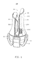
- FIG. 1 illustrates an embodiment of a wireless charging device 100 for vehicles.
- the wireless charging device 100 can be configured to charge an electronic device (not shown).
- the wireless charging device 100 for vehicles can include a socket 10 and a charging holder 20 elastically mounted in the socket 10.
- the socket 10 can be placed in a cup holder or other space in a vehicle.
- the charging holder 20 can be substantially a cylinder.
- the socket 10 can be pressed through an extrusion of the cup holder or other space of the vehicle to detachably clamp the charging holder 20, and the charging holder 20 can be securely mounted in the vehicle.
- the wireless charging device 100 for vehicles can be used in different vehicles.
- the charging holder 20 can be easily removed from the socket 10.
- the socket 10 can include a spring portion 11 distributed in a substantially petal shape.
- the charging holder 20 can include a base 21, a first sidewall 22 and a second sidewall 23 extended from the base 21, and an opening 24 between the first sidewall 22 and the second sidewall 23.
- a position of the second sidewall 23 adjacent to the base 21 can define a universal serial bus (USB) port 2321.
- the USB port 2321 can be a micro USB port or a universal parallel bus port.
- the opening 24 can be configured to receive electronic devices (not shown) of different sizes.
- FIG. 2 illustrates that the socket 10 can further include a protruding portion 12 in the substantially central position of the spring portion 11.
- the spring portion 11 can include a first elastic sheet 111, a second elastic sheet 112, a third elastic sheet 113, and a fourth elastic sheet 114 coupled together and surrounding the protruding portion 12.
- the spring portion 11 can include two, three, or more elastic sheets.
- the plurality of elastic sheets can be coupled together.
- the first elastic sheet 111 can include a connection portion 1111 connected to the protruding portion 12, an inclined portion 1112, and a clamping portion 1113.
- the connection portion 1111 can have a characteristic of high-elasticity and can be hard to break.
- the connection portion 1111 can extend upward to form the inclined portion 1112.
- the inclined portion 1112 can extend upward to form the clamping portion 1113.
- the structures of the second elastic sheet 112, the third elastic sheet 113 and the fourth elastic sheet 114 can be the same as that of the first elastic sheet 111.
- the protruding portion 12 can be a substantial cylinder, and hollow to conserve materials.
- the protruding portion 12 can be configured to mount and support the charging holder 20 (shown in FIG. 1 ).
- the first elastic sheet 111, the second elastic sheet 112, the third elastic sheet 113 and the fourth elastic sheet 114 can be pressed towards the protruding portion 12 by external pressure extrusion, and the charging holder 20 can be steadily mounted to the protruding portion 12.
- FIG. 3 illustrates that the base 21 can include a first claw 211, a second claw 212, a third claw 213, and a fourth claw 214 coupled together.
- the base 21 can include a plurality of claws, such as two, three, or more claws, and the number of claws can be same as the number of elastic sheets.
- a receiving portion 215 can be defined between the first claw 211 and the fourth claw 214.
- the first elastic sheet 111 (shown in FIG. 1 ) can be elastically received in the receiving portion 215.
- the structures of the second claw 212, the third claw 213, and the fourth claw 214 can be the same as that of the first claw 211.
- the first sidewall 22 can include a substantially "L"-shaped panel 221 adjacent to the opening 24 and an arc-shaped side panel 222 connected to edges of the panel 221.
- An elastic clamping portion 2211 can be located in the panel 221.
- a spring (not shown) or a substantially “V"-shaped metal dome (not shown) in the first sidewall 22 can provide rebound to the elastic clamping portion 2211.
- the elastic clamping portion 2211 can move towards or away from the panel 221 elastically.
- a structure of the second sidewall 23 can be substantially the same as the first sidewall 22.
- the second sidewall 23 can include a panel 231, an arc-shaped side panel 232 connected to edges of the panel 231, and a wireless charging module 233 located in the second sidewall 23.
- the wireless charging module 233 can be located between the panel 231 and the side panel 232.
- Another position of the second sidewall 23 adjacent to the base 21 can define a micro-universal serial bus (USB) port 2322.
- the micro-USB port 2322 can be a USB port or a universal parallel bus port.
- a height of the second sidewall 23 can be higher than that of the first sidewall 22 to allow the electronic device to be inserted into the opening 24 along the panel 231.
- a wireless communication module 234 can be mounted in the second sidewall 23, and the wireless communication module 234 can be located between the panel 231 and the side panel 232. In other embodiments, the wireless communication module 234 can be located in the first sidewall 22 or other places.
- the wireless communication module 234 can be a BLUETOOTH module or a near-field-communication (NFC) module.
- the electronic device can be inserted into the opening 24, and resisted against the second sidewall 23 elastically by the elasticity of the elastic clamping portion 2211. Then, the wireless charging module 233 can charge the electronic device.
- the wireless communication module 234 can wirelessly connect the electronic device to the vehicle, and the wireless communication module 234 can transmit data via wireless connection between the electronic device and a computer (not shown) or a media terminal (not shown) of the vehicle for transmission.
Landscapes
- Engineering & Computer Science (AREA)
- Mechanical Engineering (AREA)
- Power Engineering (AREA)
- Charge And Discharge Circuits For Batteries Or The Like (AREA)
- Power Sources (AREA)
- Transceivers (AREA)
- Telephone Set Structure (AREA)
- Telephone Function (AREA)
Abstract
A wireless charging device 100 for vehicles includes a socket 10 and a charging holder 20 mounted to the socket. The wireless charging device for vehicles is configured to charge an electronic device. The socket includes a petal shaped spring portion 11 and a protruding portion formed in the center of the spring portion. The charging holder includes a base 21, a first sidewall 22, a second sidewall 23, and an opening 24 between the first sidewall and the second sidewall. The second sidewall includes a wireless charging module 233. The wireless charging device for vehicles of the present disclosure can charge different sizes of electronic devices and can be stable and convenient.
Description
- The subject matter herein generally relates to a wireless charging device, and in particular to a wireless charging device that can be used in a vehicle.
- Wireless communication devices need to be charged. A wireless charging device is a non-contact type charging system based on electromagnetic induction. The wireless charging device is employed to supply electric power for charging the battery of wireless communication devices wirelessly. Thus, the battery can be charged easily without requiring a wire.
- According to one aspect of the disclosure, a vehicle wireless charging device configured to charge an electronic device includes a socket and a charging holder elastically mounted to the socket. The socket can be pressed through an extrusion of a cup holder or other space of the vehicle to detachably clamp the charging holder, and the charging holder can be securely mounted in the vehicle. The socket can include a petal shaped spring portion and a protruding portion formed in the center of the spring portion. The charging holder can include a base, a first sidewall, a second sidewall, and an opening between the first sidewall and the second sidewall. The second sidewall can include a wireless charging module. The electronic device can be inserted into the opening, and resisted against the second sidewall elastically. Then, the wireless charging module can charge the electronic device.
- Implementations of the present technology will now be described, by way of example only, with reference to the attached figures.
-
FIG. 1 is an isometric view of an embodiment of a wireless charging device for vehicles. -
FIG. 2 is an isometric view of a socket of the wireless charging device for vehicles as shown inFIG. 1 . -
FIG. 3 is an isometric view of a charging holder of the wireless charging device for vehicles as shown inFIG. 1 . - It will be appreciated that for simplicity and clarity of illustration, where appropriate, reference numerals have been repeated among the different figures to indicate corresponding or analogous elements. In addition, numerous specific details are set forth in order to provide a thorough understanding of the embodiments described herein. However, it will be understood by those of ordinary skill in the art that the embodiments described herein can be practiced without these specific details. In other instances, methods, procedures, and components have not been described in detail so as not to obscure the related relevant feature being described. Also, the description is not to be considered as limiting the scope of the embodiments described herein.
- Several definitions that apply throughout this disclosure will now be presented.
- The term "substantially" is defined to be essentially conforming to the particular dimension, shape, or other feature that the term modifies, such that the component need not be exact. For example, "substantially cylindrical" means that the object resembles a cylinder, but can have one or more deviations from a true cylinder. The term "comprising" when utilized, means "including, but not necessarily limited to"; it specifically indicates open-ended inclusion or membership in the so-described combination, group, series and the like.
-
FIG. 1 illustrates an embodiment of awireless charging device 100 for vehicles. Thewireless charging device 100 can be configured to charge an electronic device (not shown). Thewireless charging device 100 for vehicles can include asocket 10 and acharging holder 20 elastically mounted in thesocket 10. Thesocket 10 can be placed in a cup holder or other space in a vehicle. Thecharging holder 20 can be substantially a cylinder. - The
socket 10 can be pressed through an extrusion of the cup holder or other space of the vehicle to detachably clamp thecharging holder 20, and thecharging holder 20 can be securely mounted in the vehicle. Thus, thewireless charging device 100 for vehicles can be used in different vehicles. When thesocket 10 is taken out of the cup holder, thecharging holder 20 can be easily removed from thesocket 10. - The
socket 10 can include aspring portion 11 distributed in a substantially petal shape. Thecharging holder 20 can include abase 21, afirst sidewall 22 and asecond sidewall 23 extended from thebase 21, and an opening 24 between thefirst sidewall 22 and thesecond sidewall 23. A position of thesecond sidewall 23 adjacent to thebase 21 can define a universal serial bus (USB)port 2321. In other embodiments, theUSB port 2321 can be a micro USB port or a universal parallel bus port. Theopening 24 can be configured to receive electronic devices (not shown) of different sizes. -
FIG. 2 illustrates that thesocket 10 can further include a protrudingportion 12 in the substantially central position of thespring portion 11. Thespring portion 11 can include a firstelastic sheet 111, a secondelastic sheet 112, a thirdelastic sheet 113, and a fourthelastic sheet 114 coupled together and surrounding the protrudingportion 12. In other embodiments, thespring portion 11 can include two, three, or more elastic sheets. The plurality of elastic sheets can be coupled together. The firstelastic sheet 111 can include aconnection portion 1111 connected to theprotruding portion 12, aninclined portion 1112, and aclamping portion 1113. Theconnection portion 1111 can have a characteristic of high-elasticity and can be hard to break. Theconnection portion 1111 can extend upward to form theinclined portion 1112. Theinclined portion 1112 can extend upward to form theclamping portion 1113. The structures of the secondelastic sheet 112, the thirdelastic sheet 113 and the fourthelastic sheet 114 can be the same as that of the firstelastic sheet 111. - The protruding
portion 12 can be a substantial cylinder, and hollow to conserve materials. The protrudingportion 12 can be configured to mount and support the charging holder 20 (shown inFIG. 1 ). The firstelastic sheet 111, the secondelastic sheet 112, the thirdelastic sheet 113 and the fourthelastic sheet 114 can be pressed towards the protrudingportion 12 by external pressure extrusion, and thecharging holder 20 can be steadily mounted to the protrudingportion 12. -
FIG. 3 illustrates that thebase 21 can include afirst claw 211, asecond claw 212, athird claw 213, and afourth claw 214 coupled together. In other embodiments, thebase 21 can include a plurality of claws, such as two, three, or more claws, and the number of claws can be same as the number of elastic sheets. A receivingportion 215 can be defined between thefirst claw 211 and thefourth claw 214. The first elastic sheet 111 (shown inFIG. 1 ) can be elastically received in thereceiving portion 215. The structures of thesecond claw 212, thethird claw 213, and thefourth claw 214 can be the same as that of thefirst claw 211. - The
first sidewall 22 can include a substantially "L"-shaped panel 221 adjacent to the opening 24 and an arc-shaped side panel 222 connected to edges of thepanel 221. Anelastic clamping portion 2211 can be located in thepanel 221. A spring (not shown) or a substantially "V"-shaped metal dome (not shown) in thefirst sidewall 22 can provide rebound to theelastic clamping portion 2211. Theelastic clamping portion 2211 can move towards or away from thepanel 221 elastically. - A structure of the
second sidewall 23 can be substantially the same as thefirst sidewall 22. Thesecond sidewall 23 can include apanel 231, an arc-shapedside panel 232 connected to edges of thepanel 231, and awireless charging module 233 located in thesecond sidewall 23. Thewireless charging module 233 can be located between thepanel 231 and theside panel 232. Another position of thesecond sidewall 23 adjacent to the base 21 can define a micro-universal serial bus (USB)port 2322. In other embodiments, themicro-USB port 2322 can be a USB port or a universal parallel bus port. In the illustrated embodiment, a height of thesecond sidewall 23 can be higher than that of thefirst sidewall 22 to allow the electronic device to be inserted into theopening 24 along thepanel 231. - A
wireless communication module 234 can be mounted in thesecond sidewall 23, and thewireless communication module 234 can be located between thepanel 231 and theside panel 232. In other embodiments, thewireless communication module 234 can be located in thefirst sidewall 22 or other places. Thewireless communication module 234 can be a BLUETOOTH module or a near-field-communication (NFC) module.
The electronic device can be inserted into theopening 24, and resisted against thesecond sidewall 23 elastically by the elasticity of theelastic clamping portion 2211. Then, thewireless charging module 233 can charge the electronic device. Thewireless communication module 234 can wirelessly connect the electronic device to the vehicle, and thewireless communication module 234 can transmit data via wireless connection between the electronic device and a computer (not shown) or a media terminal (not shown) of the vehicle for transmission. - The embodiments shown and described above are only examples. Many details are often found in the art such as the other features of a wireless charging device for vehicles. Therefore, many such details are neither shown nor described. Even though numerous characteristics and advantages of the present technology have been set forth in the foregoing description, together with details of the structure and function of the present disclosure, the disclosure is illustrative only, and changes may be made in the details, especially in matters of shape, size, and arrangement of the parts within the principles of the present disclosure, up to and including the full extent established by the broad general meaning of the terms used in the claims. It will therefore be appreciated that the embodiments described above may be modified within the scope of the claims.
Claims (10)
- A wireless charging device for vehicles configured to charge an electronic device, comprising:a socket comprising
a spring portion distributed in a petal shape;
a protruding portion in the central position of the spring portion; anda charging holder mounted in the socket, comprising
a base;
a first sidewall and a second sidewall extended from the base, and
an opening between the first sidewall and the second sidewall;wherein the opening is configured for receiving the electronic device, and
a wireless charging module is located in the second sidewall. - The wireless charging device for vehicles as claimed in claim 1, wherein the first sidewall comprises a panel adjacent to the opening, and an arc-shaped side panel connected to edges of the panel.
- The wireless charging device for vehicles as claimed in claim 2, wherein an elastic clamping portion is located in the panel.
- The wireless charging device for vehicles as claimed in claim 1, wherein the spring portion comprises a plurality of elastic sheets coupled together.
- The wireless charging device for vehicles as claimed in claim 4, wherein each elastic sheet comprises a connection portion connected to the protruding portion, an inclined portion, and a clamping portion.
- The wireless charging device for vehicles as claimed in claim 4, wherein the base comprises a plurality of claws.
- The wireless charging device for vehicles as claimed in claim 6, wherein
a plurality of receiving portions are defined between the claws, and
the receiving portions are configured for receiving the elastic sheets. - The wireless charging device for vehicles as claimed in claim 1, wherein the second sidewall comprises a panel adjacent to the opening, and an arc-shaped side panel is connected to edges of the panel.
- The wireless charging device for vehicles as claimed in claim 1, wherein a position of the second sidewall adjacent to the base defines a universal bus port.
- The wireless charging device for vehicles as claimed in claim 1, wherein a wireless communication module is mounted in the second sidewall, and the wireless communication module wirelessly connects the electronic device to the vehicle.
Applications Claiming Priority (1)
| Application Number | Priority Date | Filing Date | Title |
|---|---|---|---|
| TW103125930A TW201605142A (en) | 2014-07-30 | 2014-07-30 | Vehicle-mounted wireless charging device |
Publications (1)
| Publication Number | Publication Date |
|---|---|
| EP2979930A1 true EP2979930A1 (en) | 2016-02-03 |
Family
ID=52997266
Family Applications (1)
| Application Number | Title | Priority Date | Filing Date |
|---|---|---|---|
| EP15163908.5A Withdrawn EP2979930A1 (en) | 2014-07-30 | 2015-04-16 | Wireless charging device for vehicles |
Country Status (4)
| Country | Link |
|---|---|
| US (1) | US9490655B2 (en) |
| EP (1) | EP2979930A1 (en) |
| JP (1) | JP2016034227A (en) |
| TW (1) | TW201605142A (en) |
Cited By (3)
| Publication number | Priority date | Publication date | Assignee | Title |
|---|---|---|---|---|
| WO2019101621A1 (en) * | 2017-11-27 | 2019-05-31 | Elektrosil Systeme Der Elektronik Gmbh | Charging device for wirelessly charging a mobile terminal |
| US10343576B1 (en) | 2018-01-22 | 2019-07-09 | Ford Global Technologies, Llc | Adjustable cup holder for holding tall cups, bottles and the like |
| US10850656B2 (en) | 2018-03-16 | 2020-12-01 | Ford Global Technologies, Llc | Apparatus including inductive charger and retractable cup holder |
Families Citing this family (7)
| Publication number | Priority date | Publication date | Assignee | Title |
|---|---|---|---|---|
| US9755447B2 (en) * | 2014-04-04 | 2017-09-05 | Carling Technologies, Inc. | Panel mounted USB charger |
| TWD167744S (en) * | 2014-07-30 | 2015-05-11 | 鴻海精密工業股份有限公司 | Vehicle charging device |
| US9851178B2 (en) * | 2015-07-10 | 2017-12-26 | Frank T. Cosso | Laser sight with proximity sensor |
| US20180041059A1 (en) * | 2016-08-03 | 2018-02-08 | Mark & Draw Inc | Multi-purpose storage container having cover for charging stand |
| CN107124021B (en) * | 2017-06-02 | 2023-05-16 | 惠州市华阳多媒体电子有限公司 | Vehicle-mounted wireless charging device |
| JP7218715B2 (en) * | 2019-12-09 | 2023-02-07 | 豊田合成株式会社 | Wireless power supply unit |
| IT202300017613A1 (en) * | 2023-08-25 | 2025-02-25 | Stellantis Europe Spa | PORTABLE ELECTRONIC DEVICE HOLDER FOR AUTOMOTIVE USE |
Citations (10)
| Publication number | Priority date | Publication date | Assignee | Title |
|---|---|---|---|---|
| JP2000037047A (en) * | 1998-07-15 | 2000-02-02 | Mitsumi Electric Co Ltd | Inductive charging device |
| US20070281619A1 (en) * | 2006-06-02 | 2007-12-06 | Mike Chen | Multimedia device |
| US20080079388A1 (en) * | 2006-10-03 | 2008-04-03 | Visteon Global Technologies, Inc. | Wireless charging device |
| JP2008178234A (en) * | 2007-01-19 | 2008-07-31 | Toko Inc | Non-contact power transmission device |
| US20110062916A1 (en) * | 2009-09-17 | 2011-03-17 | Qualcomm Incorporated | Movable magnetically resonant antenna for wireless charging |
| DE102012102109A1 (en) * | 2011-03-24 | 2012-09-27 | Visteon Global Technologies, Inc. | External haptic generator for portable electronic devices |
| US20130257147A1 (en) * | 2012-04-03 | 2013-10-03 | Global Ip Holdings, Llc | Assembly capable of simultaneously supporting and wirelessly supplying electrical power to a portable electronic device within a passenger compartment of a vehicle |
| CN103840516A (en) * | 2013-06-18 | 2014-06-04 | 苏州旲烔机电科技有限公司 | Vehicle-mounted wireless charger |
| CN103840517A (en) * | 2013-06-18 | 2014-06-04 | 苏州旲烔机电科技有限公司 | Wireless charging fixing device of terminal |
| DE102013200811A1 (en) * | 2013-01-18 | 2014-07-24 | Novero Dabendorf Gmbh | Holding device for a wirelessly coupleable terminal and method for producing a holding device |
Family Cites Families (5)
| Publication number | Priority date | Publication date | Assignee | Title |
|---|---|---|---|---|
| US7548040B2 (en) * | 2005-07-28 | 2009-06-16 | Zerog Wireless, Inc. | Wireless battery charging of electronic devices such as wireless headsets/headphones |
| US7746028B1 (en) * | 2006-03-24 | 2010-06-29 | Plantronics, Inc. | Headset charging cradle |
| US8294300B2 (en) * | 2008-01-14 | 2012-10-23 | Qualcomm Incorporated | Wireless powering and charging station |
| JP5443934B2 (en) * | 2009-10-06 | 2014-03-19 | ヤマハ株式会社 | Connected equipment |
| CA2788091C (en) * | 2010-01-27 | 2017-01-03 | Cynetic Designs Ltd. | Modular pocket with inductive power and data |
-
2014
- 2014-07-30 TW TW103125930A patent/TW201605142A/en unknown
- 2014-10-09 US US14/510,977 patent/US9490655B2/en not_active Expired - Fee Related
-
2015
- 2015-02-03 JP JP2015019129A patent/JP2016034227A/en active Pending
- 2015-04-16 EP EP15163908.5A patent/EP2979930A1/en not_active Withdrawn
Patent Citations (10)
| Publication number | Priority date | Publication date | Assignee | Title |
|---|---|---|---|---|
| JP2000037047A (en) * | 1998-07-15 | 2000-02-02 | Mitsumi Electric Co Ltd | Inductive charging device |
| US20070281619A1 (en) * | 2006-06-02 | 2007-12-06 | Mike Chen | Multimedia device |
| US20080079388A1 (en) * | 2006-10-03 | 2008-04-03 | Visteon Global Technologies, Inc. | Wireless charging device |
| JP2008178234A (en) * | 2007-01-19 | 2008-07-31 | Toko Inc | Non-contact power transmission device |
| US20110062916A1 (en) * | 2009-09-17 | 2011-03-17 | Qualcomm Incorporated | Movable magnetically resonant antenna for wireless charging |
| DE102012102109A1 (en) * | 2011-03-24 | 2012-09-27 | Visteon Global Technologies, Inc. | External haptic generator for portable electronic devices |
| US20130257147A1 (en) * | 2012-04-03 | 2013-10-03 | Global Ip Holdings, Llc | Assembly capable of simultaneously supporting and wirelessly supplying electrical power to a portable electronic device within a passenger compartment of a vehicle |
| DE102013200811A1 (en) * | 2013-01-18 | 2014-07-24 | Novero Dabendorf Gmbh | Holding device for a wirelessly coupleable terminal and method for producing a holding device |
| CN103840516A (en) * | 2013-06-18 | 2014-06-04 | 苏州旲烔机电科技有限公司 | Vehicle-mounted wireless charger |
| CN103840517A (en) * | 2013-06-18 | 2014-06-04 | 苏州旲烔机电科技有限公司 | Wireless charging fixing device of terminal |
Cited By (3)
| Publication number | Priority date | Publication date | Assignee | Title |
|---|---|---|---|---|
| WO2019101621A1 (en) * | 2017-11-27 | 2019-05-31 | Elektrosil Systeme Der Elektronik Gmbh | Charging device for wirelessly charging a mobile terminal |
| US10343576B1 (en) | 2018-01-22 | 2019-07-09 | Ford Global Technologies, Llc | Adjustable cup holder for holding tall cups, bottles and the like |
| US10850656B2 (en) | 2018-03-16 | 2020-12-01 | Ford Global Technologies, Llc | Apparatus including inductive charger and retractable cup holder |
Also Published As
| Publication number | Publication date |
|---|---|
| US9490655B2 (en) | 2016-11-08 |
| US20160036262A1 (en) | 2016-02-04 |
| JP2016034227A (en) | 2016-03-10 |
| TW201605142A (en) | 2016-02-01 |
Similar Documents
| Publication | Publication Date | Title |
|---|---|---|
| US9490655B2 (en) | Wireless charging device for vehicles | |
| US9096177B2 (en) | Apparatus for securing a rechargeable electronic device with respect to a surface of a wireless battery charging apparatus of a vehicle | |
| US20160105047A1 (en) | Mobile device mounting and charging system | |
| US20120019202A1 (en) | Retention of rechargeable devices | |
| EP3262850B1 (en) | Audio devices | |
| US20130119102A1 (en) | Holder Apparatus for a Portable Electronic Device | |
| EP3208136A3 (en) | A charging station for recharging eletrical vehicles | |
| CN203660606U (en) | Multifunctional wireless charger | |
| US20160036263A1 (en) | On-vehicle wireless charging system, wireless charger and car charger thereof | |
| CN202586395U (en) | Double-USB vehicle-mounted charger | |
| KR101697069B1 (en) | A station for extending power transmission | |
| US10826258B2 (en) | Combined multipath charger | |
| CN107124021B (en) | Vehicle-mounted wireless charging device | |
| EP2535984A3 (en) | Electrical connection means | |
| CN105337332A (en) | Vehicle-mounted wireless charging device | |
| US8890479B2 (en) | Holding platform for mobile information terminals, desktop telephone, and fixing method connector for mobile information terminals | |
| US10075010B2 (en) | Tablet connection system | |
| CN204688325U (en) | A kind of electronic handlebar | |
| CN209071779U (en) | Data line | |
| CN206992723U (en) | A kind of vertical wireless charging box of charge coil automatic centering | |
| KR101702244B1 (en) | Wireless charging apparatus | |
| CN207117239U (en) | Multifunctional Wireless Charging Components | |
| KR101699621B1 (en) | Connecting apparatus for wireless charging | |
| CN209844610U (en) | Vehicle-mounted cup holder type wireless charger | |
| CN202930976U (en) | Vehicle usb charger |
Legal Events
| Date | Code | Title | Description |
|---|---|---|---|
| PUAI | Public reference made under article 153(3) epc to a published international application that has entered the european phase |
Free format text: ORIGINAL CODE: 0009012 |
|
| AK | Designated contracting states |
Kind code of ref document: A1 Designated state(s): AL AT BE BG CH CY CZ DE DK EE ES FI FR GB GR HR HU IE IS IT LI LT LU LV MC MK MT NL NO PL PT RO RS SE SI SK SM TR |
|
| AX | Request for extension of the european patent |
Extension state: BA ME |
|
| STAA | Information on the status of an ep patent application or granted ep patent |
Free format text: STATUS: THE APPLICATION IS DEEMED TO BE WITHDRAWN |
|
| 18D | Application deemed to be withdrawn |
Effective date: 20160804 |