EP2979899A1 - Pneumatic tire - Google Patents
Pneumatic tire Download PDFInfo
- Publication number
- EP2979899A1 EP2979899A1 EP14774188.8A EP14774188A EP2979899A1 EP 2979899 A1 EP2979899 A1 EP 2979899A1 EP 14774188 A EP14774188 A EP 14774188A EP 2979899 A1 EP2979899 A1 EP 2979899A1
- Authority
- EP
- European Patent Office
- Prior art keywords
- tire
- carcass
- cords
- carcass cords
- pneumatic tire
- Prior art date
- Legal status (The legal status is an assumption and is not a legal conclusion. Google has not performed a legal analysis and makes no representation as to the accuracy of the status listed.)
- Granted
Links
Images
Classifications
-
- B—PERFORMING OPERATIONS; TRANSPORTING
- B60—VEHICLES IN GENERAL
- B60C—VEHICLE TYRES; TYRE INFLATION; TYRE CHANGING; CONNECTING VALVES TO INFLATABLE ELASTIC BODIES IN GENERAL; DEVICES OR ARRANGEMENTS RELATED TO TYRES
- B60C9/00—Reinforcements or ply arrangement of pneumatic tyres
- B60C9/02—Carcasses
- B60C9/04—Carcasses the reinforcing cords of each carcass ply arranged in a substantially parallel relationship
- B60C9/06—Carcasses the reinforcing cords of each carcass ply arranged in a substantially parallel relationship the cords extend diagonally from bead to bead and run in opposite directions in each successive carcass ply, i.e. bias angle ply
-
- B—PERFORMING OPERATIONS; TRANSPORTING
- B60—VEHICLES IN GENERAL
- B60C—VEHICLE TYRES; TYRE INFLATION; TYRE CHANGING; CONNECTING VALVES TO INFLATABLE ELASTIC BODIES IN GENERAL; DEVICES OR ARRANGEMENTS RELATED TO TYRES
- B60C9/00—Reinforcements or ply arrangement of pneumatic tyres
- B60C9/02—Carcasses
- B60C9/04—Carcasses the reinforcing cords of each carcass ply arranged in a substantially parallel relationship
- B60C9/08—Carcasses the reinforcing cords of each carcass ply arranged in a substantially parallel relationship the cords extend transversely from bead to bead, i.e. radial ply
- B60C9/09—Carcasses the reinforcing cords of each carcass ply arranged in a substantially parallel relationship the cords extend transversely from bead to bead, i.e. radial ply combined with other carcass plies having cords extending diagonally from bead to bead, i.e. combined radial ply and bias angle ply
-
- B—PERFORMING OPERATIONS; TRANSPORTING
- B60—VEHICLES IN GENERAL
- B60C—VEHICLE TYRES; TYRE INFLATION; TYRE CHANGING; CONNECTING VALVES TO INFLATABLE ELASTIC BODIES IN GENERAL; DEVICES OR ARRANGEMENTS RELATED TO TYRES
- B60C15/00—Tyre beads, e.g. ply turn-up or overlap
- B60C15/0009—Tyre beads, e.g. ply turn-up or overlap features of the carcass terminal portion
- B60C15/0036—Tyre beads, e.g. ply turn-up or overlap features of the carcass terminal portion with high ply turn-up, i.e. folded around the bead core and terminating radially above the point of maximum section width
- B60C15/0045—Tyre beads, e.g. ply turn-up or overlap features of the carcass terminal portion with high ply turn-up, i.e. folded around the bead core and terminating radially above the point of maximum section width with ply turn-up up to the belt edges, i.e. folded around the bead core and extending to the belt edges
-
- B—PERFORMING OPERATIONS; TRANSPORTING
- B60—VEHICLES IN GENERAL
- B60C—VEHICLE TYRES; TYRE INFLATION; TYRE CHANGING; CONNECTING VALVES TO INFLATABLE ELASTIC BODIES IN GENERAL; DEVICES OR ARRANGEMENTS RELATED TO TYRES
- B60C9/00—Reinforcements or ply arrangement of pneumatic tyres
- B60C9/02—Carcasses
- B60C9/04—Carcasses the reinforcing cords of each carcass ply arranged in a substantially parallel relationship
- B60C2009/0416—Physical properties or dimensions of the carcass cords
- B60C2009/0433—Modulus
-
- B—PERFORMING OPERATIONS; TRANSPORTING
- B60—VEHICLES IN GENERAL
- B60C—VEHICLE TYRES; TYRE INFLATION; TYRE CHANGING; CONNECTING VALVES TO INFLATABLE ELASTIC BODIES IN GENERAL; DEVICES OR ARRANGEMENTS RELATED TO TYRES
- B60C9/00—Reinforcements or ply arrangement of pneumatic tyres
- B60C9/02—Carcasses
- B60C9/04—Carcasses the reinforcing cords of each carcass ply arranged in a substantially parallel relationship
- B60C2009/0416—Physical properties or dimensions of the carcass cords
- B60C2009/0466—Twist structures
Definitions
- the present invention relates to a pneumatic tire.
- Racing tires from which high levels of steering stability are demanded when driving at high speed, may take the form of a tire having a "half-radial" structure, in which carcass cords are biased with respect to the radial direction of the tire, and the angle of the carcass cords with respect to the circumferential direction of the tire as measured at a central position in the widthwise direction of the tread is from 55 to 85°; in such tires, the carcass cords may be constituted by nylon fiber cords.
- the present invention solves the problem described above by altering the intermediate elongation values of the nylon fiber cords used in the carcass according to the location on the tire; examples of the conventional art pertaining to pneumatic tires that focus upon carcass cord intermediate elongation are as follows.
- One proposed pneumatic tire that ensures steering stability and durability while offering improved ride comfort is a pneumatic tire in which the intermediate elongation value of the carcass used in the shoulders and sides of the tire is greater than the intermediate elongation value of the carcass used at locations outside these areas (Patent Document 1).
- An object of the present invention is to provide a pneumatic tire for uses such as racing that use nylon fiber cords as carcass cords in a half-radial cord arrangement, wherein the tire is capable of sufficiently exhibiting the inherent cord properties of the nylon fiber carcass cords and has superior steering stability and durability.
- the pneumatic tire of the present invention which achieves the aforementioned object, has the arrangement described in (1) below:
- a pneumatic tire for uses such as racing that use nylon fiber cords as carcass cords in a half-radial cord arrangement, wherein the tire is capable of sufficiently exhibiting the inherent cord properties of the nylon fiber carcass cords and has superior steering stability and durability.
- a pneumatic tire that exhibits the effects of the present invention in particular with greater reliability and more prominently.
- the pneumatic tire according to the present invention is a pneumatic tire having a half-radial structure in which carcass cords are biased with respect to the radial direction of the tire and have an angle of 55 to 85° with respect to the circumferential direction of the tire as measured at a central position along the widthwise direction of the tread, the tire being characterized in that the carcass cords have an elastic modulus of 3 to 10 GPa and a twist coefficient ⁇ of 1,500 to 2,500, and a difference in intermediate elongation at 2.0 cN/dtex in the carcass cords between a central section and side sections of the tire is not more than 1.0%.
- a tread section is labeled 1
- a sidewall section is labeled 2
- a bead section is labeled 3
- belt layers are labeled 6
- a tread rubber layer is labeled 21
- a tire equatorial line is labeled CL.
- a carcass layer 4 extends between a pair of left and right bead sections 3, 3, and an end of the carcass layer 4 is folded back from the inner side of the tire around a bead core 5 toward the outside of the tire.
- the folded-back end of the carcass layer 4 may also extend to and be anchored beneath the belt layers 6.
- An embodiment is also acceptable in which the end of the carcass layer 4 is not wrapped around the bead core 5, but is positioned and anchored near the side of the bead core 5.
- the carcass layer 4 is constituted by aligned multiple carcass cords coated by a carcass compound, and the carcass cords are formed from nylon fibers.
- the carcass cords are disposed on a bias with respect to the radial direction of the tire to form a "half-radial" carcass layer; in the carcass layer 4, the angle ⁇ of the carcass cords to the circumferential direction of the tire is from 55 to 85° as measured at a central position along the widthwise direction of the tread.
- the belt layers 6 are disposed in the tread section 1 around the entire circumference of the tire to the outer circumferential side of the carcass layer 4. These belt layers 6 include reinforcing cords that are biased with respect to a tire circumferential direction and the reinforcing cords are disposed between the layers so as to intersect each other.
- An angle ⁇ of the carcass cords to the circumferential direction of the tire of less than 55° is undesirable, as the angle of the carcass cords may change due to lift during vulcanization molding, excessively increasing tread rigidity compared to side rigidity and negatively affecting ride comfort.
- An angle ⁇ of exceeding 85° is also not preferable, as this angle will reduce rigidity and steering stability.
- the carcass cords have an elastic modulus of 3 to 10 GPa and a twist coefficient ⁇ of 1,500 to 2,500, and that a difference in intermediate elongation at 2.0 cN/dtex in the carcass cords between the central section and the side sections of the tire be not more than 1.0%.
- the elastic modulus of the carcass cord is less than 3 GPa, there will be insufficient improvement in steering stability.
- the elastic modulus exceeding 10 GPa is also undesirable, as this elastic modulus will reduce the fatigue resistance of the cords, and thus tire durability.
- twist coefficient of the carcass cord is less than 1,500, the fatigue resistance of the cords will decrease, reducing tire durability. If the twist coefficient exceeds 2,500, the elastic modulus of the cords will decrease, inhibiting sufficient improvement in steering stability.
- a difference in intermediate elongation at 2.0 cN/dtex in the carcass cords between the central section and the side sections of the tire exceeding 1.0% will inhibit tensile force from being placed upon the cords in the side sections of the carcass, creating areas within the structure of the tire where the codes are slackened, with the result that steering stability and durability cannot be improved.
- a preferred minimum value for the difference in intermediate elongation is 0%.
- FIG. 3 is a cross-sectional view in the tire meridian direction illustrating locations from which measurement samples are taken when measuring the intermediate elongation of carcass cords in a central section and a side section.
- the specific method used to measure the intermediate elongation at 2.0 cN/dtex of the carcass cords in the central section and side sections will be described hereafter.
- Measurement samples are taken from a section centered on the tire equatorial line (labeled A in FIG. 3 ) for the central section, and from the turned-up section (labeled B1 in FIG. 3 ) if the tire carcass structure includes a turned-up carcass section, or from the turned-down part (labeled B2 in FIG. 3 ) if only a turned-down carcass section is present.
- the nylon carcass cords forming part of the pneumatic tire according to the present invention can be obtained by modifying manufacturing conditions to yield an elastic modulus of 3 to 10 GPa, and carcass cords having a twist coefficient ⁇ of 1,500 to 2,500 can be obtained by setting the number of twists according to the fineness of the cords to impart the predetermined twist.
- a carcass structure that allows for more secure anchoring of the ends of the carcass cords can be selected for use in the process of molding and vulcanizing the tire.
- the method of manufacturing the pneumatic tire according to the present invention preferably involves forming the tire by disposing the carcass cords so that the carcass cords are continuously disposed around the entire circumference of the tire along the circumferential direction of the tire with the beads interposed therebetween, as disclosed in Unexamined Japanese Patent Application Publication H10-225997 , or disposing nylon carcass cords so that the ends of the carcass cords wrap around the beads and back up to underneath the belt layers 6, followed by vulcanizing and molding the tire.
- the specifications for the carcass structures of the pneumatic radial tires according to the various working examples and comparative examples were as shown in table 1.
- the carcass structure described as "conventional" is the structure illustrated in FIG. 1 .
- test tires were evaluated for steering stability, ride comfort, load durability, and tire weight according to the testing/evaluation methods described in sections (B) through (D) hereafter; results are shown in table 1.
- the difference in intermediate elongation at 2.0 cN/dtex in the carcass cords between the central section and the side sections in the present invention is determined according to the method described in section (A) hereafter.
- (A) Method of determining difference in intermediate elongation at 2.0 cN/dtex in carcass cords between central section and side sections Samples for determining the intermediate elongation at 2.0 cN/dtex between the central section and the side sections in the same carcass cord in the finished pneumatic tire following vulcanization and molding were taken according to the following guidelines.
- a sample cord piece of a length capable of being subjected to a tensile test between two left and right grips spaced a total of 10 cm apart was taken from an area centered on the tire equatorial line. If a sample cord piece long enough to be tested between two left and right grips spaced a total of 10 cm apart could not be taken, the grip spacing was reduced in increments of 0.5 cm until tensile testing was possible at the length of the obtainable sample cord piece. Care was taken to obtain testable sample cord pieces that were as long as possible. If a rubber adhered to the sample cord piece, the rubber was carefully removed (likewise hereafter).
- a sample cord piece long enough to be tensile tested at a grip spacing of 10 cm was taken from the turned-up carcass section. If a sample cord piece long enough to be tested between grips spaced a total of 10 cm apart could not be taken, the grip spacing was reduced in increments of 0.5 cm until tensile testing was possible at the length of the obtainable sample cord piece. Care was taken to obtain testable sample cord pieces that were as long as possible.
- a sample cord piece long enough to be tensile tested at a grip spacing of 10 cm was taken from the turned-down carcass section. If a sample cord piece long enough to be tested between grips spaced a total of 10 cm apart could not be taken, the grip spacing was reduced in increments of 0.5 cm until tensile testing was possible at the length of the obtainable sample cord piece. Care was taken to obtain testable sample cord pieces that were as long as possible.
- the sample cord pieces were colored at two locations corresponding to the testing length (grip spacing) so as to make pre- and post-testing length apparent.
- the sample cord pieces were placed in a tensile test machine with grips set 10 cm apart so that the colored locations were aligned therewith, and tensile testing was performed by applying tensile force equivalent to 2.0 cN/dtex as determined according to the fineness (dtex) of the test cords at a rate of 300 ⁇ 20 mm/min.
- the testing was performed in a constant atmosphere of 20°C ⁇ 2°C temperature and 65 ⁇ 2% relative humidity. After the tensile force was released, the sample cord piece was removed, the distance between the colored locations was determined, and elongation (%) was determined on the basis of the measured values.
- test tires were mounted on a 2,000 cc passenger vehicle, and five test drivers drove the vehicle on a slalom test course with pylons set at fixed intervals and evaluated driving feel. Evaluation results were expressed as index values against 100 for a conventional tire. The higher the index value is, the more superior steering stability was.
- test tires were mounted on a 2,000 cc passenger vehicle, and five test drivers drove the vehicle on a straight test course having an uneven surface at 50 km/h and evaluated driving feel. Evaluation results were expressed as index values against 100 for a conventional tire. The higher the index value is, the more superior ride comfort was.
Landscapes
- Engineering & Computer Science (AREA)
- Mechanical Engineering (AREA)
- Tires In General (AREA)
Abstract
Description
- The present invention relates to a pneumatic tire.
- Racing tires, from which high levels of steering stability are demanded when driving at high speed, may take the form of a tire having a "half-radial" structure, in which carcass cords are biased with respect to the radial direction of the tire, and the angle of the carcass cords with respect to the circumferential direction of the tire as measured at a central position in the widthwise direction of the tread is from 55 to 85°; in such tires, the carcass cords may be constituted by nylon fiber cords.
- When nylon fiber cords are used as the carcass cords in a half-radial cord arrangement of this sort, the problem arises that the carcass cords become incapable of sufficiently demonstrating their inherent cord properties, leading to insufficient improvement in steering stability and durability, if setting
- (solidification) occurs while compression-directional tensile force is applied to the carcass cords when the tire is being molded or vulcanized.
- As will be discussed hereafter, the present invention solves the problem described above by altering the intermediate elongation values of the nylon fiber cords used in the carcass according to the location on the tire; examples of the conventional art pertaining to pneumatic tires that focus upon carcass cord intermediate elongation are as follows.
- One proposed pneumatic tire that ensures steering stability and durability while offering improved ride comfort is a pneumatic tire in which the intermediate elongation value of the carcass used in the shoulders and sides of the tire is greater than the intermediate elongation value of the carcass used at locations outside these areas (Patent Document 1).
- In another proposed tire, steering stability and mass are ensured while noise occurrence is suppressed by increasing the intermediate elongation value of the carcass cords located in the area below the belt layer to from 3 to 5% greater than that of that of the carcass cords in other areas (Patent Document 2).
- However, these proposed pneumatic tires differ from the tire having a "half-radial" structure constituting the focus of the present invention, in which the carcass cords are biased with respect to the radial direction of the tire and have an angle of 55 to 85° with respect to the circumferential direction of the tire as measured at a central position along the widthwise direction of the tread, and do not suggest the pneumatic tire of the present invention.
-
- Patent Document 1:
- Japanese Unexamined Patent Application Publication No.
2009-23442A - Patent Document 2:
- Japanese Unexamined Patent Application Publication No.
2006-281984A - An object of the present invention is to provide a pneumatic tire for uses such as racing that use nylon fiber cords as carcass cords in a half-radial cord arrangement, wherein the tire is capable of sufficiently exhibiting the inherent cord properties of the nylon fiber carcass cords and has superior steering stability and durability.
- The pneumatic tire of the present invention, which achieves the aforementioned object, has the arrangement described in (1) below:
- (1) a pneumatic tire having a half-radial structure in which carcass cords are biased with respect to the radial direction of the tire and have an angle of 55 to 85° with respect to the circumferential direction of the tire as measured at a central position along the widthwise direction of the tread, the tire being characterized in that the carcass cords have an elastic modulus of 3 to 10 GPa and a twist coefficient α of 1,500 to 2,500, and a difference in intermediate elongation at 2.0 cN/dtex in the carcass cords between a central section and side sections of the tire is not more than 1.0%;
the twist coefficient α being N x √T;
N being the number of twists per 10 cm of length in the fiber cords; and
T being the fineness (dtex) of the fiber cords.
The pneumatic tire according to the present invention more preferably has the arrangement set forth in (2) or (3) below. - (2) The pneumatic tire according to (1), wherein the carcass cords are continuously disposed along the entire circumference of the tire in the circumferential direction of the tire with a bead interposed therebetween.
- (3) The pneumatic tire according to (1), wherein ends of the carcass cords with a bead interposed therebetween extend to beneath a belt.
- In accordance with the present invention as in a first aspect, it is possible to provide a pneumatic tire for uses such as racing that use nylon fiber cords as carcass cords in a half-radial cord arrangement, wherein the tire is capable of sufficiently exhibiting the inherent cord properties of the nylon fiber carcass cords and has superior steering stability and durability.
- In accordance with the present invention as in a second or a third aspect in particular, a pneumatic tire is provided that exhibits the effects of the present invention in particular with greater reliability and more prominently.
-
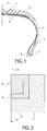
- FIG. 1
- is a cross-sectional view in the tire meridian direction of a pneumatic tire according to the present invention.
- FIG. 2
- is a partially cut-out cross-sectional view of a half-radial structure pneumatic tire according to the present invention, and illustrates a schematic view of the cord arrangement of a carcass layer and two belt layers.
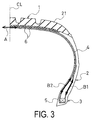
- FIG. 3
- is a cross-sectional view in the tire meridian direction illustrating locations from which measurement samples are taken when measuring the intermediate elongation of carcass cords in a central section and a side section.
- The pneumatic tire of the present invention will now be described in detail.
- The pneumatic tire according to the present invention is a pneumatic tire having a half-radial structure in which carcass cords are biased with respect to the radial direction of the tire and have an angle of 55 to 85° with respect to the circumferential direction of the tire as measured at a central position along the widthwise direction of the tread, the tire being characterized in that the carcass cords have an elastic modulus of 3 to 10 GPa and a twist coefficient α of 1,500 to 2,500, and a difference in intermediate elongation at 2.0 cN/dtex in the carcass cords between a central section and side sections of the tire is not more than 1.0%.
- The value of the twist coefficient α is calculated according to the formula α = N x √T, with N being the number of twists per 10 cm of length of the fiber cords, and T being the fineness (dtex) of the fiber cords.
- An embodiment of the pneumatic tire according to the present invention will now be described with reference to
FIGS. 1 and 2 .
InFIG. 1 , a tread section is labeled 1, a sidewall section is labeled 2, a bead section is labeled 3, belt layers are labeled 6, a tread rubber layer is labeled 21, and a tire equatorial line is labeled CL. Acarcass layer 4 extends between a pair of left and right bead sections 3, 3, and an end of thecarcass layer 4 is folded back from the inner side of the tire around abead core 5 toward the outside of the tire. Apart from the embodiment illustrated in the drawings, the folded-back end of thecarcass layer 4 may also extend to and be anchored beneath thebelt layers 6. An embodiment is also acceptable in which the end of thecarcass layer 4 is not wrapped around thebead core 5, but is positioned and anchored near the side of thebead core 5. - The
carcass layer 4 is constituted by aligned multiple carcass cords coated by a carcass compound, and the carcass cords are formed from nylon fibers. The carcass cords are disposed on a bias with respect to the radial direction of the tire to form a "half-radial" carcass layer; in thecarcass layer 4, the angle θ of the carcass cords to the circumferential direction of the tire is from 55 to 85° as measured at a central position along the widthwise direction of the tread. Meanwhile, thebelt layers 6 are disposed in the tread section 1 around the entire circumference of the tire to the outer circumferential side of thecarcass layer 4. Thesebelt layers 6 include reinforcing cords that are biased with respect to a tire circumferential direction and the reinforcing cords are disposed between the layers so as to intersect each other. - An angle θ of the carcass cords to the circumferential direction of the tire of less than 55° is undesirable, as the angle of the carcass cords may change due to lift during vulcanization molding, excessively increasing tread rigidity compared to side rigidity and negatively affecting ride comfort. An angle θ of exceeding 85° is also not preferable, as this angle will reduce rigidity and steering stability.
- In the present invention, it is essential that the carcass cords have an elastic modulus of 3 to 10 GPa and a twist coefficient α of 1,500 to 2,500, and that a difference in intermediate elongation at 2.0 cN/dtex in the carcass cords between the central section and the side sections of the tire be not more than 1.0%.
- Specifically, if the elastic modulus of the carcass cord is less than 3 GPa, there will be insufficient improvement in steering stability. The elastic modulus exceeding 10 GPa is also undesirable, as this elastic modulus will reduce the fatigue resistance of the cords, and thus tire durability.
- If the twist coefficient of the carcass cord is less than 1,500, the fatigue resistance of the cords will decrease, reducing tire durability. If the twist coefficient exceeds 2,500, the elastic modulus of the cords will decrease, inhibiting sufficient improvement in steering stability.
- A difference in intermediate elongation at 2.0 cN/dtex in the carcass cords between the central section and the side sections of the tire exceeding 1.0% will inhibit tensile force from being placed upon the cords in the side sections of the carcass, creating areas within the structure of the tire where the codes are slackened, with the result that steering stability and durability cannot be improved. A preferred minimum value for the difference in intermediate elongation is 0%.
-
FIG. 3 is a cross-sectional view in the tire meridian direction illustrating locations from which measurement samples are taken when measuring the intermediate elongation of carcass cords in a central section and a side section. The specific method used to measure the intermediate elongation at 2.0 cN/dtex of the carcass cords in the central section and side sections will be described hereafter. Measurement samples are taken from a section centered on the tire equatorial line (labeled A inFIG. 3 ) for the central section, and from the turned-up section (labeled B1 inFIG. 3 ) if the tire carcass structure includes a turned-up carcass section, or from the turned-down part (labeled B2 inFIG. 3 ) if only a turned-down carcass section is present. - An overview of a method for manufacturing the pneumatic tire according to the present invention will now be described.
The nylon carcass cords forming part of the pneumatic tire according to the present invention can be obtained by modifying manufacturing conditions to yield an elastic modulus of 3 to 10 GPa, and carcass cords having a twist coefficient α of 1,500 to 2,500 can be obtained by setting the number of twists according to the fineness of the cords to impart the predetermined twist. - To obtain a difference in intermediate elongation at 2.0 cN/dtex in the carcass cords between the central section and the side sections of the tire of no more than 1.0%, a carcass structure that allows for more secure anchoring of the ends of the carcass cords can be selected for use in the process of molding and vulcanizing the tire.
- To this end, the method of manufacturing the pneumatic tire according to the present invention preferably involves forming the tire by disposing the carcass cords so that the carcass cords are continuously disposed around the entire circumference of the tire along the circumferential direction of the tire with the beads interposed therebetween, as disclosed in Unexamined Japanese Patent Application Publication
H10-225997 belt layers 6, followed by vulcanizing and molding the tire. - The specific arrangement and effects of the pneumatic tire according to the present invention will now be described with reference to examples.
- Working Examples 1 to 3, Conventional Examples 1 to 6
Using a test tire size of 225/50 R16 92V, five tires were prepared for each working example and comparative example and mounted on JATMA standard rims to create test tires. - The specifications for the carcass structures of the pneumatic radial tires according to the various working examples and comparative examples were as shown in table 1. The carcass structure described as "conventional" is the structure illustrated in
FIG. 1 . - The test tires were evaluated for steering stability, ride comfort, load durability, and tire weight according to the testing/evaluation methods described in sections (B) through (D) hereafter; results are shown in table 1.
- The difference in intermediate elongation at 2.0 cN/dtex in the carcass cords between the central section and the side sections in the present invention is determined according to the method described in section (A) hereafter. (A) Method of determining difference in intermediate elongation at 2.0 cN/dtex in carcass cords between central section and side sections
Samples for determining the intermediate elongation at 2.0 cN/dtex between the central section and the side sections in the same carcass cord in the finished pneumatic tire following vulcanization and molding were taken according to the following guidelines. - For the central section, a sample cord piece of a length capable of being subjected to a tensile test between two left and right grips spaced a total of 10 cm apart was taken from an area centered on the tire equatorial line. If a sample cord piece long enough to be tested between two left and right grips spaced a total of 10 cm apart could not be taken, the grip spacing was reduced in increments of 0.5 cm until tensile testing was possible at the length of the obtainable sample cord piece. Care was taken to obtain testable sample cord pieces that were as long as possible. If a rubber adhered to the sample cord piece, the rubber was carefully removed (likewise hereafter).
- For the side section, if the tire had a carcass structure comprising a section of the carcass that was turned up around the bead section, a sample cord piece long enough to be tensile tested at a grip spacing of 10 cm was taken from the turned-up carcass section. If a sample cord piece long enough to be tested between grips spaced a total of 10 cm apart could not be taken, the grip spacing was reduced in increments of 0.5 cm until tensile testing was possible at the length of the obtainable sample cord piece. Care was taken to obtain testable sample cord pieces that were as long as possible.
- If the tire had a carcass structure comprising only turned-down sections, a sample cord piece long enough to be tensile tested at a grip spacing of 10 cm was taken from the turned-down carcass section. If a sample cord piece long enough to be tested between grips spaced a total of 10 cm apart could not be taken, the grip spacing was reduced in increments of 0.5 cm until tensile testing was possible at the length of the obtainable sample cord piece. Care was taken to obtain testable sample cord pieces that were as long as possible.
- The sample cord pieces were colored at two locations corresponding to the testing length (grip spacing) so as to make pre- and post-testing length apparent.
The sample cord pieces were placed in a tensile test machine with grips set 10 cm apart so that the colored locations were aligned therewith, and tensile testing was performed by applying tensile force equivalent to 2.0 cN/dtex as determined according to the fineness (dtex) of the test cords at a rate of 300 ± 20 mm/min. The testing was performed in a constant atmosphere of 20°C ± 2°C temperature and 65 ± 2% relative humidity. After the tensile force was released, the sample cord piece was removed, the distance between the colored locations was determined, and elongation (%) was determined on the basis of the measured values. - Elongation (%) was calculated to one decimal place according to the following formula.

- Testing was performed five times, an average value was determined, and the average value was rounded to a single decimal place to determine the elongation (%) of the sample.
- The test described above was performed on the central section and the two side sections of the carcass cords, and the difference in values for elongation (%) so obtained was taken as the difference (%) in intermediate elongation at 2.0 cN/dtex between the central section and the side sections of the carcass cords.
- The test tires were mounted on a 2,000 cc passenger vehicle, and five test drivers drove the vehicle on a slalom test course with pylons set at fixed intervals and evaluated driving feel.
Evaluation results were expressed as index values against 100 for a conventional tire. The higher the index value is, the more superior steering stability was. - The test tires were mounted on a 2,000 cc passenger vehicle, and five test drivers drove the vehicle on a straight test course having an uneven surface at 50 km/h and evaluated driving feel. Evaluation results were expressed as index values against 100 for a conventional tire. The higher the index value is, the more superior ride comfort was.
- After completing a load durability test according to JIS D-4230 at a drum diameter of 1707 mm, the load was increased at a rate of 20%/5 hours, and testing was continued until the tire ruptured. Durability was evaluated by determining the total length of time until the test tire ruptured. Evaluation results are expressed as index values against 100 for a conventional tire (conventional example 1); the higher the index value is, the better the load durability of the tire was.
- As is clear from the results shown in table 1, the pneumatic tire of the present invention exhibits a superb balance of superior ride comfort, steering stability, and durability.
[Table 1] Conventional Example 1 Conventional Example 2 Conventional Example 3 Conventional Example 4 Conventional Example 5 Carcass structure Conventional Conventional Conventional Conventional Conventional Angle (°) of carcass cord with respect to tire circumferential direction 70 45 90 70 70 Elastic modulus (GPa) of carcass cord 5 6 4.5 13 1.5 Twist coefficient of carcass cord 2000 1800 2100 3000 3200 Difference (%) in intermediate elongation in carcass cords between central section and side sections of tire 2.5 3 2 1.5 3.5 Ride comfort performance 100 85 95 90 105 Steering stability 100 90 80 105 80 Durability 100 95 102 85 105 Conventional Example 6 Working Example 1 Working Example 2 Working Example 3 Carcass structure Conventional Conventional Continuously wrapped TU-end belt suspended Angle (°) of carcass cord with respect to tire circumferential direction 70 70 70 70 Elastic modulus (GPa) of carcass cord 7 5 5 5 Twist coefficient of carcass cord 1000 2000 2000 2000 Difference (%) in intermediate elongation in carcass cords between central section and side sections of tire 2.5 0.7 0.3 0.3 Ride comfort performance 92 102 105 105 Steering stability 102 110 115 115 Durability 90 105 105 105 -
- 1:
- Tread section
- 2:
- Sidewall section
- 3:
- Bead section
- 4:
- Carcass layer
- 5:
- Bead core
- 6:
- Belt layer
- 21:
- Tread rubber layer
- CL:
- Tire equatorial line
- A:
- Sampling location for test piece (carcass cord piece) used to measure intermediate elongation
- B1:
- Sampling location for test piece (carcass cord piece) used to measure intermediate elongation
- B2:
- Sampling location for test piece (carcass cord piece) used to measure intermediate elongation
Claims (3)
- A pneumatic tire having
a half-radial structure in which carcass cords are biased with respect to a radial direction of the tire and have an angle of 55 to 85° with respect to a circumferential direction of the tire as measured at a central position along a widthwise direction of a tread,
the tire being characterized in that
the carcass cords have an elastic modulus of 3 to 10 GPa and a twist coefficient α of 1,500 to 2,500 and
a difference in intermediate elongation at 2.0 cN/dtex in the carcass cords between a central section and side sections of the tire is not more than 1.0%; the twist coefficient α being N x √T;
N being the number of twists per 10 cm of length in the fiber cords; and
T being a fineness (dtex) of the fiber cords. - The pneumatic tire according to claim 1, wherein
the carcass cords are continuously disposed along an entire circumference of the tire in the circumferential direction of the tire with a bead interposed therebetween. - The pneumatic tire according to claim 1, wherein
the carcass cords are disposed so that bead-end sections thereof wrap around a bead portion and extend to underneath a belt layer.
Applications Claiming Priority (2)
| Application Number | Priority Date | Filing Date | Title |
|---|---|---|---|
| JP2013072741 | 2013-03-29 | ||
| PCT/JP2014/059254 WO2014157656A1 (en) | 2013-03-29 | 2014-03-28 | Pneumatic tire |
Publications (3)
| Publication Number | Publication Date |
|---|---|
| EP2979899A1 true EP2979899A1 (en) | 2016-02-03 |
| EP2979899A4 EP2979899A4 (en) | 2016-11-30 |
| EP2979899B1 EP2979899B1 (en) | 2017-11-29 |
Family
ID=51624612
Family Applications (1)
| Application Number | Title | Priority Date | Filing Date |
|---|---|---|---|
| EP14774188.8A Active EP2979899B1 (en) | 2013-03-29 | 2014-03-28 | Pneumatic tire |
Country Status (5)
| Country | Link |
|---|---|
| US (1) | US20160046155A1 (en) |
| EP (1) | EP2979899B1 (en) |
| JP (1) | JP5987973B2 (en) |
| CN (1) | CN105102241B (en) |
| WO (1) | WO2014157656A1 (en) |
Families Citing this family (7)
| Publication number | Priority date | Publication date | Assignee | Title |
|---|---|---|---|---|
| JP6922403B2 (en) * | 2017-05-15 | 2021-08-18 | 住友ゴム工業株式会社 | Pneumatic bias tires and their manufacturing methods |
| JP7107255B2 (en) * | 2019-03-07 | 2022-07-27 | 横浜ゴム株式会社 | pneumatic tire |
| JP6954321B2 (en) * | 2019-03-07 | 2021-10-27 | 横浜ゴム株式会社 | Pneumatic tires |
| JP7279617B2 (en) * | 2019-11-11 | 2023-05-23 | 横浜ゴム株式会社 | pneumatic tire |
| JP7211376B2 (en) * | 2020-01-27 | 2023-01-24 | 横浜ゴム株式会社 | pneumatic tire |
| EP4357158B1 (en) * | 2022-10-21 | 2026-02-18 | Sumitomo Rubber Industries, Ltd. | Pneumatic tire |
| EP4357159B1 (en) * | 2022-10-21 | 2025-09-10 | Sumitomo Rubber Industries, Ltd. | Pneumatic tire |
Family Cites Families (18)
| Publication number | Priority date | Publication date | Assignee | Title |
|---|---|---|---|---|
| JPH01321939A (en) * | 1988-06-20 | 1989-12-27 | Yokohama Rubber Co Ltd:The | Pneumatic tire |
| JP3794657B2 (en) * | 1997-02-14 | 2006-07-05 | 横浜ゴム株式会社 | Method and apparatus for manufacturing carcass structure for pneumatic tire and method for manufacturing pneumatic tire |
| US5871600A (en) * | 1997-05-29 | 1999-02-16 | The Goodyear Tire & Rubber Company | Runflat tire with different modulus or elongation carcass cords |
| JPH11278013A (en) * | 1998-03-26 | 1999-10-12 | Yokohama Rubber Co Ltd:The | Pneumatic radial tire for passenger car |
| JP2001001715A (en) * | 1999-06-24 | 2001-01-09 | Bridgestone Corp | Pneumatic tire for two-wheeled vehicle |
| JP4043245B2 (en) * | 2002-01-31 | 2008-02-06 | 横浜ゴム株式会社 | Pneumatic tire and manufacturing method thereof |
| JP2004001628A (en) * | 2002-05-31 | 2004-01-08 | Sumitomo Rubber Ind Ltd | Pneumatic radial tire and carcass cord used therefor |
| JP3902211B2 (en) * | 2002-08-29 | 2007-04-04 | 旭化成せんい株式会社 | Polyketone fiber and method for producing the same |
| JP4299516B2 (en) * | 2002-09-04 | 2009-07-22 | 住友ゴム工業株式会社 | Pneumatic tire manufacturing method and tire vulcanizing mold |
| US7823616B2 (en) * | 2005-01-21 | 2010-11-02 | Bridgestone Corporation | Pneumatic radial tire with belt reinforcing layer cord having specified heat shrinkage stress |
| JP2006281984A (en) | 2005-03-31 | 2006-10-19 | Yokohama Rubber Co Ltd:The | Pneumatic tire |
| JP4621127B2 (en) * | 2005-12-13 | 2011-01-26 | 住友ゴム工業株式会社 | Pneumatic tire |
| JP4857954B2 (en) * | 2006-06-28 | 2012-01-18 | 横浜ゴム株式会社 | Pneumatic tire |
| JP2008174167A (en) * | 2007-01-22 | 2008-07-31 | Bridgestone Corp | Pneumatic tire |
| JP2008290503A (en) * | 2007-05-22 | 2008-12-04 | Yokohama Rubber Co Ltd:The | Pneumatic radial tire |
| JP2009023442A (en) | 2007-07-18 | 2009-02-05 | Yokohama Rubber Co Ltd:The | Pneumatic tire |
| JP5200690B2 (en) * | 2008-06-20 | 2013-06-05 | 横浜ゴム株式会社 | Pneumatic tire |
| JP5416449B2 (en) * | 2009-03-27 | 2014-02-12 | 住友ゴム工業株式会社 | Pneumatic tire |
-
2014
- 2014-03-28 JP JP2015508783A patent/JP5987973B2/en active Active
- 2014-03-28 EP EP14774188.8A patent/EP2979899B1/en active Active
- 2014-03-28 WO PCT/JP2014/059254 patent/WO2014157656A1/en not_active Ceased
- 2014-03-28 CN CN201480017222.2A patent/CN105102241B/en active Active
- 2014-03-28 US US14/781,277 patent/US20160046155A1/en not_active Abandoned
Also Published As
| Publication number | Publication date |
|---|---|
| EP2979899B1 (en) | 2017-11-29 |
| JP5987973B2 (en) | 2016-09-07 |
| WO2014157656A1 (en) | 2014-10-02 |
| CN105102241A (en) | 2015-11-25 |
| JPWO2014157656A1 (en) | 2017-02-16 |
| EP2979899A4 (en) | 2016-11-30 |
| CN105102241B (en) | 2017-05-10 |
| US20160046155A1 (en) | 2016-02-18 |
Similar Documents
| Publication | Publication Date | Title |
|---|---|---|
| EP2979899B1 (en) | Pneumatic tire | |
| US6609552B2 (en) | Pneumatic tire with single-twist organic filter band cords | |
| KR101869147B1 (en) | Hybrid cord and tire using the same | |
| EP2783842B1 (en) | Method for manufacturing pneumatic tire | |
| EP2065223B1 (en) | Pneumatic radial tire | |
| US8490667B2 (en) | Pneumatic tire | |
| EP3305549A1 (en) | Pneumatic tire | |
| EP3552841B1 (en) | Pneumatic tire | |
| US20120118467A1 (en) | Tyre for a motor vehicle and method for controlling a motor vehicle during a manoeuvre to change direction and/or speed | |
| EP1213159B1 (en) | Motorcycle tires and method of producing the same | |
| JP6442228B2 (en) | Pneumatic tires for passenger cars | |
| US20260103028A1 (en) | Tyre for racing bicycle wheels | |
| US20090283193A1 (en) | Steel cord for reinforcing rubber article and pneumatic radial tire | |
| US8578989B2 (en) | Motor vehicle tire | |
| EP1905616A2 (en) | Pneumatic radial tire | |
| US20180370297A1 (en) | Run flat tire and method for manufacturing same | |
| EP3943660A1 (en) | Tire | |
| JP7156928B2 (en) | pneumatic tire | |
| JP7156927B2 (en) | pneumatic tire | |
| JP4331843B2 (en) | Pneumatic tire | |
| JPH0747804A (en) | High-performance pneumatic radial tire | |
| RU2343079C2 (en) | Pneumatic tyre with reinforced side construction |
Legal Events
| Date | Code | Title | Description |
|---|---|---|---|
| PUAI | Public reference made under article 153(3) epc to a published international application that has entered the european phase |
Free format text: ORIGINAL CODE: 0009012 |
|
| 17P | Request for examination filed |
Effective date: 20151029 |
|
| AK | Designated contracting states |
Kind code of ref document: A1 Designated state(s): AL AT BE BG CH CY CZ DE DK EE ES FI FR GB GR HR HU IE IS IT LI LT LU LV MC MK MT NL NO PL PT RO RS SE SI SK SM TR |
|
| AX | Request for extension of the european patent |
Extension state: BA ME |
|
| DAX | Request for extension of the european patent (deleted) | ||
| A4 | Supplementary search report drawn up and despatched |
Effective date: 20161103 |
|
| RIC1 | Information provided on ipc code assigned before grant |
Ipc: B60C 9/08 20060101ALI20161026BHEP Ipc: B60C 9/02 20060101AFI20161026BHEP Ipc: B60C 9/00 20060101ALI20161026BHEP |
|
| REG | Reference to a national code |
Ref country code: DE Ref legal event code: R079 Ref document number: 602014017959 Country of ref document: DE Free format text: PREVIOUS MAIN CLASS: B60C0009020000 Ipc: B60C0009040000 |
|
| RIC1 | Information provided on ipc code assigned before grant |
Ipc: B60C 9/04 20060101AFI20170616BHEP Ipc: B60C 9/06 20060101ALI20170616BHEP Ipc: B60C 15/00 20060101ALI20170616BHEP |
|
| GRAP | Despatch of communication of intention to grant a patent |
Free format text: ORIGINAL CODE: EPIDOSNIGR1 |
|
| STAA | Information on the status of an ep patent application or granted ep patent |
Free format text: STATUS: GRANT OF PATENT IS INTENDED |
|
| INTG | Intention to grant announced |
Effective date: 20170802 |
|
| GRAS | Grant fee paid |
Free format text: ORIGINAL CODE: EPIDOSNIGR3 |
|
| GRAA | (expected) grant |
Free format text: ORIGINAL CODE: 0009210 |
|
| STAA | Information on the status of an ep patent application or granted ep patent |
Free format text: STATUS: THE PATENT HAS BEEN GRANTED |
|
| AK | Designated contracting states |
Kind code of ref document: B1 Designated state(s): AL AT BE BG CH CY CZ DE DK EE ES FI FR GB GR HR HU IE IS IT LI LT LU LV MC MK MT NL NO PL PT RO RS SE SI SK SM TR |
|
| REG | Reference to a national code |
Ref country code: CH Ref legal event code: EP |
|
| REG | Reference to a national code |
Ref country code: AT Ref legal event code: REF Ref document number: 950029 Country of ref document: AT Kind code of ref document: T Effective date: 20171215 |
|
| REG | Reference to a national code |
Ref country code: IE Ref legal event code: FG4D |
|
| REG | Reference to a national code |
Ref country code: DE Ref legal event code: R096 Ref document number: 602014017959 Country of ref document: DE |
|
| REG | Reference to a national code |
Ref country code: NL Ref legal event code: MP Effective date: 20171129 |
|
| REG | Reference to a national code |
Ref country code: LT Ref legal event code: MG4D |
|
| REG | Reference to a national code |
Ref country code: AT Ref legal event code: MK05 Ref document number: 950029 Country of ref document: AT Kind code of ref document: T Effective date: 20171129 |
|
| PG25 | Lapsed in a contracting state [announced via postgrant information from national office to epo] |
Ref country code: FI Free format text: LAPSE BECAUSE OF FAILURE TO SUBMIT A TRANSLATION OF THE DESCRIPTION OR TO PAY THE FEE WITHIN THE PRESCRIBED TIME-LIMIT Effective date: 20171129 Ref country code: SE Free format text: LAPSE BECAUSE OF FAILURE TO SUBMIT A TRANSLATION OF THE DESCRIPTION OR TO PAY THE FEE WITHIN THE PRESCRIBED TIME-LIMIT Effective date: 20171129 Ref country code: NO Free format text: LAPSE BECAUSE OF FAILURE TO SUBMIT A TRANSLATION OF THE DESCRIPTION OR TO PAY THE FEE WITHIN THE PRESCRIBED TIME-LIMIT Effective date: 20180228 Ref country code: ES Free format text: LAPSE BECAUSE OF FAILURE TO SUBMIT A TRANSLATION OF THE DESCRIPTION OR TO PAY THE FEE WITHIN THE PRESCRIBED TIME-LIMIT Effective date: 20171129 Ref country code: LT Free format text: LAPSE BECAUSE OF FAILURE TO SUBMIT A TRANSLATION OF THE DESCRIPTION OR TO PAY THE FEE WITHIN THE PRESCRIBED TIME-LIMIT Effective date: 20171129 |
|
| PG25 | Lapsed in a contracting state [announced via postgrant information from national office to epo] |
Ref country code: HR Free format text: LAPSE BECAUSE OF FAILURE TO SUBMIT A TRANSLATION OF THE DESCRIPTION OR TO PAY THE FEE WITHIN THE PRESCRIBED TIME-LIMIT Effective date: 20171129 Ref country code: LV Free format text: LAPSE BECAUSE OF FAILURE TO SUBMIT A TRANSLATION OF THE DESCRIPTION OR TO PAY THE FEE WITHIN THE PRESCRIBED TIME-LIMIT Effective date: 20171129 Ref country code: BG Free format text: LAPSE BECAUSE OF FAILURE TO SUBMIT A TRANSLATION OF THE DESCRIPTION OR TO PAY THE FEE WITHIN THE PRESCRIBED TIME-LIMIT Effective date: 20180228 Ref country code: RS Free format text: LAPSE BECAUSE OF FAILURE TO SUBMIT A TRANSLATION OF THE DESCRIPTION OR TO PAY THE FEE WITHIN THE PRESCRIBED TIME-LIMIT Effective date: 20171129 Ref country code: GR Free format text: LAPSE BECAUSE OF FAILURE TO SUBMIT A TRANSLATION OF THE DESCRIPTION OR TO PAY THE FEE WITHIN THE PRESCRIBED TIME-LIMIT Effective date: 20180301 Ref country code: AT Free format text: LAPSE BECAUSE OF FAILURE TO SUBMIT A TRANSLATION OF THE DESCRIPTION OR TO PAY THE FEE WITHIN THE PRESCRIBED TIME-LIMIT Effective date: 20171129 |
|
| PG25 | Lapsed in a contracting state [announced via postgrant information from national office to epo] |
Ref country code: NL Free format text: LAPSE BECAUSE OF FAILURE TO SUBMIT A TRANSLATION OF THE DESCRIPTION OR TO PAY THE FEE WITHIN THE PRESCRIBED TIME-LIMIT Effective date: 20171129 |
|
| PG25 | Lapsed in a contracting state [announced via postgrant information from national office to epo] |
Ref country code: DK Free format text: LAPSE BECAUSE OF FAILURE TO SUBMIT A TRANSLATION OF THE DESCRIPTION OR TO PAY THE FEE WITHIN THE PRESCRIBED TIME-LIMIT Effective date: 20171129 Ref country code: SK Free format text: LAPSE BECAUSE OF FAILURE TO SUBMIT A TRANSLATION OF THE DESCRIPTION OR TO PAY THE FEE WITHIN THE PRESCRIBED TIME-LIMIT Effective date: 20171129 Ref country code: EE Free format text: LAPSE BECAUSE OF FAILURE TO SUBMIT A TRANSLATION OF THE DESCRIPTION OR TO PAY THE FEE WITHIN THE PRESCRIBED TIME-LIMIT Effective date: 20171129 Ref country code: CY Free format text: LAPSE BECAUSE OF FAILURE TO SUBMIT A TRANSLATION OF THE DESCRIPTION OR TO PAY THE FEE WITHIN THE PRESCRIBED TIME-LIMIT Effective date: 20171129 Ref country code: CZ Free format text: LAPSE BECAUSE OF FAILURE TO SUBMIT A TRANSLATION OF THE DESCRIPTION OR TO PAY THE FEE WITHIN THE PRESCRIBED TIME-LIMIT Effective date: 20171129 |
|
| REG | Reference to a national code |
Ref country code: DE Ref legal event code: R097 Ref document number: 602014017959 Country of ref document: DE |
|
| PG25 | Lapsed in a contracting state [announced via postgrant information from national office to epo] |
Ref country code: IT Free format text: LAPSE BECAUSE OF FAILURE TO SUBMIT A TRANSLATION OF THE DESCRIPTION OR TO PAY THE FEE WITHIN THE PRESCRIBED TIME-LIMIT Effective date: 20171129 Ref country code: SM Free format text: LAPSE BECAUSE OF FAILURE TO SUBMIT A TRANSLATION OF THE DESCRIPTION OR TO PAY THE FEE WITHIN THE PRESCRIBED TIME-LIMIT Effective date: 20171129 Ref country code: PL Free format text: LAPSE BECAUSE OF FAILURE TO SUBMIT A TRANSLATION OF THE DESCRIPTION OR TO PAY THE FEE WITHIN THE PRESCRIBED TIME-LIMIT Effective date: 20171129 Ref country code: RO Free format text: LAPSE BECAUSE OF FAILURE TO SUBMIT A TRANSLATION OF THE DESCRIPTION OR TO PAY THE FEE WITHIN THE PRESCRIBED TIME-LIMIT Effective date: 20171129 |
|
| PLBE | No opposition filed within time limit |
Free format text: ORIGINAL CODE: 0009261 |
|
| STAA | Information on the status of an ep patent application or granted ep patent |
Free format text: STATUS: NO OPPOSITION FILED WITHIN TIME LIMIT |
|
| REG | Reference to a national code |
Ref country code: CH Ref legal event code: PL |
|
| 26N | No opposition filed |
Effective date: 20180830 |
|
| GBPC | Gb: european patent ceased through non-payment of renewal fee |
Effective date: 20180328 |
|
| PG25 | Lapsed in a contracting state [announced via postgrant information from national office to epo] |
Ref country code: MC Free format text: LAPSE BECAUSE OF FAILURE TO SUBMIT A TRANSLATION OF THE DESCRIPTION OR TO PAY THE FEE WITHIN THE PRESCRIBED TIME-LIMIT Effective date: 20171129 Ref country code: SI Free format text: LAPSE BECAUSE OF FAILURE TO SUBMIT A TRANSLATION OF THE DESCRIPTION OR TO PAY THE FEE WITHIN THE PRESCRIBED TIME-LIMIT Effective date: 20171129 |
|
| REG | Reference to a national code |
Ref country code: BE Ref legal event code: MM Effective date: 20180331 |
|
| REG | Reference to a national code |
Ref country code: IE Ref legal event code: MM4A |
|
| PG25 | Lapsed in a contracting state [announced via postgrant information from national office to epo] |
Ref country code: LU Free format text: LAPSE BECAUSE OF NON-PAYMENT OF DUE FEES Effective date: 20180328 |
|
| PG25 | Lapsed in a contracting state [announced via postgrant information from national office to epo] |
Ref country code: IE Free format text: LAPSE BECAUSE OF NON-PAYMENT OF DUE FEES Effective date: 20180328 |
|
| PG25 | Lapsed in a contracting state [announced via postgrant information from national office to epo] |
Ref country code: GB Free format text: LAPSE BECAUSE OF NON-PAYMENT OF DUE FEES Effective date: 20180328 Ref country code: BE Free format text: LAPSE BECAUSE OF NON-PAYMENT OF DUE FEES Effective date: 20180331 Ref country code: LI Free format text: LAPSE BECAUSE OF NON-PAYMENT OF DUE FEES Effective date: 20180331 Ref country code: CH Free format text: LAPSE BECAUSE OF NON-PAYMENT OF DUE FEES Effective date: 20180331 |
|
| PG25 | Lapsed in a contracting state [announced via postgrant information from national office to epo] |
Ref country code: FR Free format text: LAPSE BECAUSE OF NON-PAYMENT OF DUE FEES Effective date: 20180331 |
|
| PG25 | Lapsed in a contracting state [announced via postgrant information from national office to epo] |
Ref country code: MT Free format text: LAPSE BECAUSE OF NON-PAYMENT OF DUE FEES Effective date: 20180328 |
|
| PG25 | Lapsed in a contracting state [announced via postgrant information from national office to epo] |
Ref country code: TR Free format text: LAPSE BECAUSE OF FAILURE TO SUBMIT A TRANSLATION OF THE DESCRIPTION OR TO PAY THE FEE WITHIN THE PRESCRIBED TIME-LIMIT Effective date: 20171129 |
|
| PG25 | Lapsed in a contracting state [announced via postgrant information from national office to epo] |
Ref country code: PT Free format text: LAPSE BECAUSE OF FAILURE TO SUBMIT A TRANSLATION OF THE DESCRIPTION OR TO PAY THE FEE WITHIN THE PRESCRIBED TIME-LIMIT Effective date: 20171129 |
|
| PG25 | Lapsed in a contracting state [announced via postgrant information from national office to epo] |
Ref country code: HU Free format text: LAPSE BECAUSE OF FAILURE TO SUBMIT A TRANSLATION OF THE DESCRIPTION OR TO PAY THE FEE WITHIN THE PRESCRIBED TIME-LIMIT; INVALID AB INITIO Effective date: 20140328 Ref country code: MK Free format text: LAPSE BECAUSE OF NON-PAYMENT OF DUE FEES Effective date: 20171129 |
|
| PG25 | Lapsed in a contracting state [announced via postgrant information from national office to epo] |
Ref country code: AL Free format text: LAPSE BECAUSE OF FAILURE TO SUBMIT A TRANSLATION OF THE DESCRIPTION OR TO PAY THE FEE WITHIN THE PRESCRIBED TIME-LIMIT Effective date: 20171129 Ref country code: IS Free format text: LAPSE BECAUSE OF FAILURE TO SUBMIT A TRANSLATION OF THE DESCRIPTION OR TO PAY THE FEE WITHIN THE PRESCRIBED TIME-LIMIT Effective date: 20180329 |
|
| P01 | Opt-out of the competence of the unified patent court (upc) registered |
Effective date: 20230512 |
|
| PGFP | Annual fee paid to national office [announced via postgrant information from national office to epo] |
Ref country code: DE Payment date: 20260204 Year of fee payment: 13 |