EP2979874A1 - Printhead cleaning assembly - Google Patents
Printhead cleaning assembly Download PDFInfo
- Publication number
- EP2979874A1 EP2979874A1 EP15164948.0A EP15164948A EP2979874A1 EP 2979874 A1 EP2979874 A1 EP 2979874A1 EP 15164948 A EP15164948 A EP 15164948A EP 2979874 A1 EP2979874 A1 EP 2979874A1
- Authority
- EP
- European Patent Office
- Prior art keywords
- printhead
- belt
- wiper
- cleaning
- cleaning solution
- Prior art date
- Legal status (The legal status is an assumption and is not a legal conclusion. Google has not performed a legal analysis and makes no representation as to the accuracy of the status listed.)
- Granted
Links
Images


Classifications
-
- B—PERFORMING OPERATIONS; TRANSPORTING
- B41—PRINTING; LINING MACHINES; TYPEWRITERS; STAMPS
- B41J—TYPEWRITERS; SELECTIVE PRINTING MECHANISMS, i.e. MECHANISMS PRINTING OTHERWISE THAN FROM A FORME; CORRECTION OF TYPOGRAPHICAL ERRORS
- B41J2/00—Typewriters or selective printing mechanisms characterised by the printing or marking process for which they are designed
- B41J2/005—Typewriters or selective printing mechanisms characterised by the printing or marking process for which they are designed characterised by bringing liquid or particles selectively into contact with a printing material
- B41J2/01—Ink jet
- B41J2/135—Nozzles
- B41J2/165—Prevention or detection of nozzle clogging, e.g. cleaning, capping or moistening for nozzles
- B41J2/16517—Cleaning of print head nozzles
- B41J2/16535—Cleaning of print head nozzles using wiping constructions
- B41J2/16538—Cleaning of print head nozzles using wiping constructions with brushes or wiper blades perpendicular to the nozzle plate
-
- B—PERFORMING OPERATIONS; TRANSPORTING
- B41—PRINTING; LINING MACHINES; TYPEWRITERS; STAMPS
- B41J—TYPEWRITERS; SELECTIVE PRINTING MECHANISMS, i.e. MECHANISMS PRINTING OTHERWISE THAN FROM A FORME; CORRECTION OF TYPOGRAPHICAL ERRORS
- B41J2/00—Typewriters or selective printing mechanisms characterised by the printing or marking process for which they are designed
- B41J2/005—Typewriters or selective printing mechanisms characterised by the printing or marking process for which they are designed characterised by bringing liquid or particles selectively into contact with a printing material
- B41J2/01—Ink jet
- B41J2/135—Nozzles
- B41J2/165—Prevention or detection of nozzle clogging, e.g. cleaning, capping or moistening for nozzles
- B41J2/16517—Cleaning of print head nozzles
- B41J2/16535—Cleaning of print head nozzles using wiping constructions
-
- B—PERFORMING OPERATIONS; TRANSPORTING
- B41—PRINTING; LINING MACHINES; TYPEWRITERS; STAMPS
- B41J—TYPEWRITERS; SELECTIVE PRINTING MECHANISMS, i.e. MECHANISMS PRINTING OTHERWISE THAN FROM A FORME; CORRECTION OF TYPOGRAPHICAL ERRORS
- B41J2/00—Typewriters or selective printing mechanisms characterised by the printing or marking process for which they are designed
- B41J2/005—Typewriters or selective printing mechanisms characterised by the printing or marking process for which they are designed characterised by bringing liquid or particles selectively into contact with a printing material
- B41J2/01—Ink jet
- B41J2/135—Nozzles
- B41J2/165—Prevention or detection of nozzle clogging, e.g. cleaning, capping or moistening for nozzles
- B41J2/16517—Cleaning of print head nozzles
- B41J2/16535—Cleaning of print head nozzles using wiping constructions
- B41J2/16541—Means to remove deposits from wipers or scrapers
-
- B—PERFORMING OPERATIONS; TRANSPORTING
- B41—PRINTING; LINING MACHINES; TYPEWRITERS; STAMPS
- B41J—TYPEWRITERS; SELECTIVE PRINTING MECHANISMS, i.e. MECHANISMS PRINTING OTHERWISE THAN FROM A FORME; CORRECTION OF TYPOGRAPHICAL ERRORS
- B41J2/00—Typewriters or selective printing mechanisms characterised by the printing or marking process for which they are designed
- B41J2/005—Typewriters or selective printing mechanisms characterised by the printing or marking process for which they are designed characterised by bringing liquid or particles selectively into contact with a printing material
- B41J2/01—Ink jet
- B41J2/135—Nozzles
- B41J2/165—Prevention or detection of nozzle clogging, e.g. cleaning, capping or moistening for nozzles
- B41J2/16517—Cleaning of print head nozzles
- B41J2/16535—Cleaning of print head nozzles using wiping constructions
- B41J2/16544—Constructions for the positioning of wipers
- B41J2/16547—Constructions for the positioning of wipers the wipers and caps or spittoons being on the same movable support
-
- B—PERFORMING OPERATIONS; TRANSPORTING
- B41—PRINTING; LINING MACHINES; TYPEWRITERS; STAMPS
- B41J—TYPEWRITERS; SELECTIVE PRINTING MECHANISMS, i.e. MECHANISMS PRINTING OTHERWISE THAN FROM A FORME; CORRECTION OF TYPOGRAPHICAL ERRORS
- B41J2/00—Typewriters or selective printing mechanisms characterised by the printing or marking process for which they are designed
- B41J2/005—Typewriters or selective printing mechanisms characterised by the printing or marking process for which they are designed characterised by bringing liquid or particles selectively into contact with a printing material
- B41J2/01—Ink jet
- B41J2/135—Nozzles
- B41J2/165—Prevention or detection of nozzle clogging, e.g. cleaning, capping or moistening for nozzles
- B41J2/16517—Cleaning of print head nozzles
- B41J2/16552—Cleaning of print head nozzles using cleaning fluids
-
- B—PERFORMING OPERATIONS; TRANSPORTING
- B41—PRINTING; LINING MACHINES; TYPEWRITERS; STAMPS
- B41J—TYPEWRITERS; SELECTIVE PRINTING MECHANISMS, i.e. MECHANISMS PRINTING OTHERWISE THAN FROM A FORME; CORRECTION OF TYPOGRAPHICAL ERRORS
- B41J2/00—Typewriters or selective printing mechanisms characterised by the printing or marking process for which they are designed
- B41J2/005—Typewriters or selective printing mechanisms characterised by the printing or marking process for which they are designed characterised by bringing liquid or particles selectively into contact with a printing material
- B41J2/01—Ink jet
- B41J2/135—Nozzles
- B41J2/165—Prevention or detection of nozzle clogging, e.g. cleaning, capping or moistening for nozzles
- B41J2/16585—Prevention or detection of nozzle clogging, e.g. cleaning, capping or moistening for nozzles for paper-width or non-reciprocating print heads
Definitions
- the invention relates to the field of printing, and in particular, to printing systems.
- Inkjet printers are used for a variety of purposes, from desktop to production printing.
- an inkjet production printer is a high-speed printer used for volume printing (e.g., one hundred pages per minute or more), and may include continuous-forms printers that print on a web of print media stored on a large roll. While a continuous-forms inkjet printer operates, the web is quickly passed underneath the nozzles of printheads of the printer, which discharge ink onto the web at intervals to form pixels.
- Embodiments described herein provide a printhead cleaning assembly. Wipers run across the surface of a printhead to collect any residual ink leftover on the printhead after printing operation.
- the wipers are affixed around a rotating belt so that when the belt motions in a loop, the wipers at the top of the loop clean the printhead and the wipers at the bottom of the loop are cleaned in a fluid.
- the cleaning assembly thus ensures that the wipers (and therefore the printhead cleaned by the wipers) remain clean even after long periods of use, with little or no manual maintenance needed to clean the wipers.
- One embodiment is a cleaning unit for a printhead of a printer that includes a belt configured to rotate in a loop, and a wiper attached to the belt configured to wipe ink from the printhead.
- the cleaning unit also includes a tank configured as a reservoir for a cleaning solution, and a drive unit configured to drive the belt so that an end of the wiper is able to drag across the printhead when in an upper portion of the loop and able to submerge in the cleaning solution of the tank when in a lower portion of the loop.
- a printhead cleaning system comprising a print engine operable to mark a web medium, the print engine including a printhead.
- the printhead cleaning system also includes a wiper attached to an outer perimeter of a belt, and a positioning system configured to position the belt underneath a printhead so that the wiper contacts the printhead.
- the printhead cleaning system also includes a drive system is configured to rotate the belt a first distance to cause the wiper to remove ink from the printhead, and to rotate the belt a second distance to cause the wiper to submerge in a liquid.
- Yet another embodiment is a system that includes a print engine operable to mark a web medium, the print engine including a printhead.
- the system also includes a plurality of wipers attached around an outer perimeter of a belt that is configured to move the plurality of wipers in a revolving motion.
- the system also includes a tank configured as a reservoir for a cleaning solution. When the belt rotates, a first wiper drags across a printhead while a second wiper passes through the cleaning solution.
- FIG. 1 is a block diagram of a printing system 100 in an exemplary embodiment.
- the printing system 100 comprises any system, device, or component operable to mark print media (e.g., paper) by applying ink (e.g., pigment inks or dye inks) onto the media.
- the printing system 100 comprises a continuous-forms printer 110 that marks a web of print media 120.
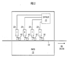
- FIG. 2 is a block diagram illustrating an inside view of printer 110 in an exemplary embodiment.
- FIG. 2 illustrates, in simplified form, that the printer 110 includes multiple printheads 220.
- the printer 110 may include a print engine operable to mark the web of the print media 120 with one or more printhead assemblies, with each assembly including a printhead controller 210 and a printhead 220 (or an array of printheads 220).
- each printhead 220 is used to dispense a color of ink (e.g., Cyan, Magenta, Yellow, or Key black) onto print media 120.
- each printhead 220 includes nozzles for each of multiple different colors of ink.
- the operations of printheads 220 are directed by the print controller 210.
- the print controller 210 may instruct the printheads 220 to mark specific pixel locations on the media 120 during printing. In between print operations, the print controller 210 may initiate cleaning operations of the printheads 220 through operation of one or more printhead cleaning assemblies 300.
- the printer controller 210 may be implemented, for example, as custom circuitry, as a processor executing programmed instructions stored in an associated program memory, or some combination thereof.
- FIG. 3 is a block diagram illustrating a printhead cleaning assembly 300 in an exemplary embodiment.
- Printhead cleaning assembly 300 includes a belt 302 that rotates under the power of one or more drive roller(s) 304 and may be additionally supported by one or more idle rollers 306.
- the printhead cleaning assembly 300 further includes one or more wipers 310 attached to the belt 302 which move with the belt 302 in the direction shown.
- the wipers 310 may be comprised of an elastic material (e.g., rubber, an elastic polymer, etc.) that are driven across the printhead plate 224 of the printhead 220 in order to remove residual droplets of ink 226 from each printhead nozzle 222.
- the wiping action may leave a residual amount of ink on a wiper which may dry and degrade the ability of that wiper to clean printheads.
- the printhead cleaning assembly 300 is therefore further enhanced with a tank 320 configured to retain a cleaning solution 322 that washes and/or lubricates the wipers 310 as the wipers 310 rotate.
- the print controller 210 operates a drain 324 in the tank 320 to open/close for draining/collecting the cleaning solution 322.
- the print controller 210 also operates a spout 326 to replenish the tank 320 with the cleaning solution 322.
- the print controller 210 may receive input from sensors, timers, users, etc., that help inform appropriate drainage/collection of cleaning solution 322 in tank 320.
- the same rotating action of belt 302 that wipes the printhead plate 224 with the wipers 310 also cleans (e.g., submerges, washes, scrapes, lubricates, etc.) the wipers 310 on the other side of the belt 302.
- the printhead cleaning assembly 300 provides a relative short period of time between when ink is collected on a wiper and when that wiper is submerged in the cleaning solution 322 to eliminate or at least reduce the chance that ink is able to accumulate on the wipers 310.
- the self-cleaning wiper mechanism described herein reduces manual maintenance for the printheads and the wipers that clean the printheads.
- the tank 320 also includes a blade 328 that scrapes the wipers 310 when the wipers 310 rotate past the blade 328 to remove congealed/residual ink from the wiper 310.
- the blade 328 may be positioned in tank 320 at a far end from where the wipers 310 are initially submerged (as shown in FIG. 3 ) in the cleaning solution 322 to give sufficient time for any dried ink on the wipers 310 to loosen/dissolve in the cleaning solution 322 before being scraped by the blade 328.
- the blade 328 may be submerged in the cleaning solution 322 so that after the surface of the wiper 310 is scraped by the blade 328 it is lubricated by the cleaning solution 322 prior to engaging or re-engaging with the printhead plate 224.
- alternative embodiments are possible, including a tank with a blade attached in a different location, a non-submerged blade, multiple blades, no blade, etc.
- the print controller 210 may initiate printhead cleaning at regular intervals or in response to an event (e.g., after a certain number of pages, at the end of each job, after a specific time interval, after a cleaning or flushing cycle of the printhead 220, etc.). If viscous inks are used by the printheads 220, a cleaning operation may be initiated more often to ensure that the printhead nozzles 222 do not clog. Alternatively or additionally, a print operator may initiate a printhead cleaning operation via a graphical user interface of the printer 110.
- the printhead cleaning assembly 300 may be positioned in a home storage location (e. g. , elsewhere in printer 110) so as not to obstruct printing operation of the printheads 220.
- a positioning system (not shown) is operable to position the printhead cleaning assembly 300 underneath the targeted printhead(s) 220 to be cleaned.
- the print controller 210 may direct the positioning system to return the printhead cleaning assembly 300 to the home storage location.
- the print controller 210 may also manage maintenance of the printhead cleaning assembly 300.
- the print controller 210 may receive input, either manually (e.g., command sent from a print operator) or automatically (e.g., fluid sensors, timers, print events, number of printhead cleaning operations, etc.), that a sufficient level of ink from the printheads 220 has accumulated in the cleaning solution 322.
- the print controller 210 may initiate a sequence to direct the drain 324 to purge the cleaning solution 322 from the tank 320 so that a fresh supply of the cleaning solution 322 may be replenished in the tank 320 via the spout 326.
- the print controller 210 directs a drive system to rotate the belt 302 while the spout 326 sprays the cleaning solution 322 toward the wipers 310 as the wipers 310 move past the spout 326.
- the spray of the cleaning solution 322 contacts the wipers 310 in a sliding vertical motion as the wipers 310 move closer to the spout 326 with the rotation action of the belt 302, thereby removing/loosening ink residue buildup on the wipers 310.
- the print controller 210 may, at some point during this process, close the drain 324 while spraying the cleaning solution 322 at the wipers 310 with the spout 326 in order to simultaneously recollect the cleaning solution 322 in the tank 320 in preparation for subsequent printhead cleaning operations.
- the print controller 210 may also be configured to perform additional, more extensive printhead cleaning operations.
- the printhead cleaning assembly 300 includes a jet 330 configured to spray a mist of the cleaning solution 322 toward the printhead 220. Direct application of the cleaning solution 322 to the printhead 222 helps dissolve, loosen, and/or remove residual ink 226 from the printhead 220, and may be performed separately or in addition to the rotating action that drags the wipers 310 across the printhead 220.
- the print controller 210 directs the jet 330 to spray the cleaning solution 322 as the printhead cleaning assembly 300 moves into position to the clean printhead 220.
- the printhead(s) 220 may be lifted vertically while a positioning system moves the printhead cleaning assembly 300 (laterally and/or vertically) into a position vertically underneath the printhead(s) 220.
- the jet 330 As the cleaning assembly nears a the printhead 220 to be cleaned, the jet 330, being attached to the cleaning assembly 300 and a supply of the cleaning solution 322 (either from the source of the tank 320 or elsewhere in the printer 110), shoots a mist of the cleaning solution 322 toward the surface of the printhead plate 224 to lubricate the printhead plate 224.
- the lateral movement of the printhead cleaning assembly 300 as it positions underneath the printhead 220 allows the jet 330 to a target cleaning solution 322 at the printhead 220 for the length of the printhead 220 and collect any debris/fluid that falls from the printhead 220 in the tank 320. This operation may be performed in addition and/or prior to the wiping of the printhead 220 with the wipers 310.
- the printhead cleaning assembly 300 advantageously maintains the wipers 310 while performing other cleaning operation routines. For instance, the wipers 310 may be rotated into the cleaning solution 322 while the printhead cleaning assembly 300 remains engaged with the printhead 220, while the printhead cleaning assembly 300 positions to a subsequent printhead, while the printhead cleaning assembly 300 positions to a storage location away from the printheads 220 so that printing operation may resume, or while the printhead cleaning assembly 300 cleans the subsequent printhead.
- the number of the wipers 310 attached to the belt 302 may vary by matter of design choice, but may be selected such that printhead cleanliness is maximized while printhead wear is minimized.
- the print controller 210 is configured to direct a belt drive system to rotate the belt 302 a distance that substantially matches the length of the printhead 220 and then pause so that wear is minimized.
- belt 302 may be configured in shapes other than that shown in FIG. 3 that allow a wiper 310 affixed to the belt 302 to cycle around with continued rotation of the belt 302.
- the belt 302 is configured in a loop such that a top portion of the loop is parallel with the surface of the printhead 220 and a bottom portion of the loop submerges at least the tips of the wipers 310 in the cleaning solution 322 collected in the tank 320.
- the wipers 310 and/or the belt 302 may completely submerge in the cleaning solution 322 at portions of the loop as a matter of design choice.
- the belt 302 and the wipers 310 may rotate, and the printhead cleaning assembly 300 may be positioned, using any suitable drive systems (e.g., motors, tracks, etc. in addition to or as part of any suitable combination of drive rollers 304, idle rollers 306, the belt drive system, the positioning system, etc.).
- the wipers 310 and the belt 302 may rotate in the opposing direction (e.g., to additionally clean the printhead 220 and/or the wipers 310).
- the belt 302 includes at least two wipers 310 disposed on relatively opposite sides of the loop of the belt 302 such that cleaning of the printhead 220 and cleaning of at least one wiper 310 is performed in a simultaneous fashion.
- Embodiments disclosed herein can take the form of software, hardware, firmware, or various combinations thereof.
- software is used to direct a processing system of the print server 120 to perform the various operations disclosed herein.
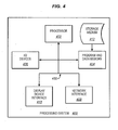
- FIG. 4 illustrates a processing system 400 configured to execute a computer readable medium embodying programmed instructions to perform desired functions in an exemplary embodiment.
- the processing system 400 is configured to perform the above operations by executing programmed instructions tangibly embodied on a computer readable storage medium 412.
- embodiments of the invention can take the form of a computer program accessible via computer-readable medium 412 providing program code for use by a computer or any other instruction execution system.
- the computer readable storage medium 412 can be anything that can contain or store the program for use by the computer.
- the computer readable storage medium 412 may be an electronic, magnetic, optical, electromagnetic, infrared, or semiconductor device. Examples of the computer readable storage medium 412 include a solid state memory, a magnetic tape, a removable computer diskette, a random access memory (RAM), a read-only memory (ROM), a rigid magnetic disk, and an optical disk. Current examples of optical disks include compact disk - read only memory (CD-ROM), compact disk - read/write (CD-RIW), and DVD.
- the processing system 400 being suitable for storing and/or executing the program code, includes at least one processor 402 coupled to a program and data memory 404 through a system bus 450.
- the program and data memory 404 may include local memory employed during actual execution of the program code, bulk storage, and cache memories that provide temporary storage of at least some program code and/or data in order to reduce the number of times the code and/or data are retrieved from bulk storage during execution.
- I/O devices 406 may be coupled either directly or through intervening I/O controllers.
- Network adapter interfaces 408 may also be integrated with the system to enable the processing system 400 to become coupled to other data processing systems or storage devices through intervening private or public networks. Modems, cable modems, SCSI, Fibre Channel, and Ethernet cards are just a few of the currently available types of network or host interface adapters.
- a presentation device interface 410 may be integrated with the system to interface to one or more presentation devices, such as printing systems and displays for presentation of presentation data generated by the processor 402.
Landscapes
- Ink Jet (AREA)
Abstract
Description
- The invention relates to the field of printing, and in particular, to printing systems.
- Inkjet printers are used for a variety of purposes, from desktop to production printing. For example, an inkjet production printer is a high-speed printer used for volume printing (e.g., one hundred pages per minute or more), and may include continuous-forms printers that print on a web of print media stored on a large roll. While a continuous-forms inkjet printer operates, the web is quickly passed underneath the nozzles of printheads of the printer, which discharge ink onto the web at intervals to form pixels.
- Although most of the ink dispensed by the printheads is transferred to the web, some amount of ink remains on the nozzles of the printheads, and this amount may vary depending on the viscosity of the ink used. In order to clean the printhead nozzles and ensure that congealed ink does not interfere with the printing process, print operators sometimes use wipers to scrape off residual ink before the ink congeals. However, residual ink accumulates on the wipers as they clean the printheads and as a result the quality and effectiveness of subsequent cleanings deteriorates over time.
- Embodiments described herein provide a printhead cleaning assembly. Wipers run across the surface of a printhead to collect any residual ink leftover on the printhead after printing operation. The wipers are affixed around a rotating belt so that when the belt motions in a loop, the wipers at the top of the loop clean the printhead and the wipers at the bottom of the loop are cleaned in a fluid. The cleaning assembly thus ensures that the wipers (and therefore the printhead cleaned by the wipers) remain clean even after long periods of use, with little or no manual maintenance needed to clean the wipers.
- One embodiment is a cleaning unit for a printhead of a printer that includes a belt configured to rotate in a loop, and a wiper attached to the belt configured to wipe ink from the printhead. The cleaning unit also includes a tank configured as a reservoir for a cleaning solution, and a drive unit configured to drive the belt so that an end of the wiper is able to drag across the printhead when in an upper portion of the loop and able to submerge in the cleaning solution of the tank when in a lower portion of the loop.
- Another embodiment is a printhead cleaning system comprising a print engine operable to mark a web medium, the print engine including a printhead. The printhead cleaning system also includes a wiper attached to an outer perimeter of a belt, and a positioning system configured to position the belt underneath a printhead so that the wiper contacts the printhead. The printhead cleaning system also includes a drive system is configured to rotate the belt a first distance to cause the wiper to remove ink from the printhead, and to rotate the belt a second distance to cause the wiper to submerge in a liquid.
- Yet another embodiment is a system that includes a print engine operable to mark a web medium, the print engine including a printhead. The system also includes a plurality of wipers attached around an outer perimeter of a belt that is configured to move the plurality of wipers in a revolving motion. The system also includes a tank configured as a reservoir for a cleaning solution. When the belt rotates, a first wiper drags across a printhead while a second wiper passes through the cleaning solution.
- The above summary provides a basic understanding of some aspects of the specification. This summary is not an extensive overview of the specification. It is not intended to identify key or critical elements of the specification nor to delineate any scope of particular embodiments of the specification, or any scope of the claims. Its sole purpose is to present some concepts of the specification in a simplified form as a prelude to the more detailed description that is presented later. Other exemplary embodiments (e.g., methods and computer-readable media relating to the foregoing embodiments) may be described below.
- Some embodiments of the present invention are now described, by way of example only, and with reference to the accompanying drawings. The same reference number represents the same element or the same type of element on all drawings.
-
FIG. 1 is a block diagram of a printing system in an exemplary embodiment; -
FIG. 2 is a block diagram illustrating an inside view of a printer in an exemplary embodiment. -
FIG. 3 is a block diagram of a printhead cleaning assembly in an exemplary embodiment; and -
FIG. 4 illustrates a processing system operable to execute a computer readable medium embodying programmed instructions to perform desired functions in an exemplary embodiment. - The figures and the following description illustrate specific exemplary embodiments. It will thus be appreciated that those skilled in the art will be able to devise various arrangements that, although not explicitly described or shown herein, embody the principles of the embodiments and are included within the scope of the embodiments. Furthermore, any examples described herein are intended to aid in understanding the principles of the embodiments, and are to be construed as being without limitation to such specifically recited examples and conditions. As a result, the inventive concept (s) is not limited to the specific embodiments or examples described below, but by the claims and their equivalents.
-
FIG. 1 is a block diagram of aprinting system 100 in an exemplary embodiment. Theprinting system 100 comprises any system, device, or component operable to mark print media (e.g., paper) by applying ink (e.g., pigment inks or dye inks) onto the media. In this embodiment, theprinting system 100 comprises a continuous-forms printer 110 that marks a web ofprint media 120. -
FIG. 2 is a block diagram illustrating an inside view ofprinter 110 in an exemplary embodiment.FIG. 2 illustrates, in simplified form, that theprinter 110 includesmultiple printheads 220. For example, theprinter 110 may include a print engine operable to mark the web of theprint media 120 with one or more printhead assemblies, with each assembly including aprinthead controller 210 and a printhead 220 (or an array of printheads 220). As shown inFIG. 2 , eachprinthead 220 is used to dispense a color of ink (e.g., Cyan, Magenta, Yellow, or Key black) ontoprint media 120. However, in alternate embodiments, eachprinthead 220 includes nozzles for each of multiple different colors of ink. - The operations of
printheads 220 are directed by theprint controller 210. For example, theprint controller 210 may instruct theprintheads 220 to mark specific pixel locations on themedia 120 during printing. In between print operations, theprint controller 210 may initiate cleaning operations of theprintheads 220 through operation of one or moreprinthead cleaning assemblies 300. Theprinter controller 210 may be implemented, for example, as custom circuitry, as a processor executing programmed instructions stored in an associated program memory, or some combination thereof. -
FIG. 3 is a block diagram illustrating aprinthead cleaning assembly 300 in an exemplary embodiment.Printhead cleaning assembly 300 includes abelt 302 that rotates under the power of one or more drive roller(s) 304 and may be additionally supported by one or moreidle rollers 306. Theprinthead cleaning assembly 300 further includes one ormore wipers 310 attached to thebelt 302 which move with thebelt 302 in the direction shown. Thewipers 310 may be comprised of an elastic material (e.g., rubber, an elastic polymer, etc.) that are driven across theprinthead plate 224 of theprinthead 220 in order to remove residual droplets ofink 226 from eachprinthead nozzle 222. In prior systems, the wiping action may leave a residual amount of ink on a wiper which may dry and degrade the ability of that wiper to clean printheads. - The
printhead cleaning assembly 300 is therefore further enhanced with atank 320 configured to retain acleaning solution 322 that washes and/or lubricates thewipers 310 as thewipers 310 rotate. Theprint controller 210 operates adrain 324 in thetank 320 to open/close for draining/collecting thecleaning solution 322. Theprint controller 210 also operates aspout 326 to replenish thetank 320 with thecleaning solution 322. Theprint controller 210 may receive input from sensors, timers, users, etc., that help inform appropriate drainage/collection ofcleaning solution 322 intank 320. - Advantageously, the same rotating action of
belt 302 that wipes theprinthead plate 224 with thewipers 310 also cleans (e.g., submerges, washes, scrapes, lubricates, etc.) thewipers 310 on the other side of thebelt 302. Moreover, theprinthead cleaning assembly 300 provides a relative short period of time between when ink is collected on a wiper and when that wiper is submerged in thecleaning solution 322 to eliminate or at least reduce the chance that ink is able to accumulate on thewipers 310. The self-cleaning wiper mechanism described herein reduces manual maintenance for the printheads and the wipers that clean the printheads. - In one embodiment, the
tank 320 also includes ablade 328 that scrapes thewipers 310 when thewipers 310 rotate past theblade 328 to remove congealed/residual ink from thewiper 310. Theblade 328 may be positioned intank 320 at a far end from where thewipers 310 are initially submerged (as shown inFIG. 3 ) in thecleaning solution 322 to give sufficient time for any dried ink on thewipers 310 to loosen/dissolve in thecleaning solution 322 before being scraped by theblade 328. Furthermore, theblade 328 may be submerged in thecleaning solution 322 so that after the surface of thewiper 310 is scraped by theblade 328 it is lubricated by thecleaning solution 322 prior to engaging or re-engaging with theprinthead plate 224. However, alternative embodiments are possible, including a tank with a blade attached in a different location, a non-submerged blade, multiple blades, no blade, etc. - The
print controller 210 may initiate printhead cleaning at regular intervals or in response to an event (e.g., after a certain number of pages, at the end of each job, after a specific time interval, after a cleaning or flushing cycle of theprinthead 220, etc.). If viscous inks are used by theprintheads 220, a cleaning operation may be initiated more often to ensure that theprinthead nozzles 222 do not clog. Alternatively or additionally, a print operator may initiate a printhead cleaning operation via a graphical user interface of theprinter 110. - During printing operation of the
printer 110, theprinthead cleaning assembly 300 may be positioned in a home storage location (e. g. , elsewhere in printer 110) so as not to obstruct printing operation of theprintheads 220. When theprint controller 210 determines to initiate printhead cleaning, a positioning system (not shown) is operable to position theprinthead cleaning assembly 300 underneath the targeted printhead(s) 220 to be cleaned. When cleaning operations are complete, theprint controller 210 may direct the positioning system to return theprinthead cleaning assembly 300 to the home storage location. - The
print controller 210 may also manage maintenance of theprinthead cleaning assembly 300. For example, theprint controller 210 may receive input, either manually (e.g., command sent from a print operator) or automatically (e.g., fluid sensors, timers, print events, number of printhead cleaning operations, etc.), that a sufficient level of ink from theprintheads 220 has accumulated in thecleaning solution 322. In response, theprint controller 210 may initiate a sequence to direct thedrain 324 to purge thecleaning solution 322 from thetank 320 so that a fresh supply of thecleaning solution 322 may be replenished in thetank 320 via thespout 326. - In one embodiment, with the
drain 324 open to purge the contaminatedcleaning solution 322, theprint controller 210 directs a drive system to rotate thebelt 302 while thespout 326 sprays thecleaning solution 322 toward thewipers 310 as thewipers 310 move past thespout 326. With thespout 326 in a fixed position in thetank 320, the spray of thecleaning solution 322 contacts thewipers 310 in a sliding vertical motion as thewipers 310 move closer to thespout 326 with the rotation action of thebelt 302, thereby removing/loosening ink residue buildup on thewipers 310. Theprint controller 210 may, at some point during this process, close thedrain 324 while spraying thecleaning solution 322 at thewipers 310 with thespout 326 in order to simultaneously recollect thecleaning solution 322 in thetank 320 in preparation for subsequent printhead cleaning operations. - The
print controller 210 may also be configured to perform additional, more extensive printhead cleaning operations. In one embodiment, theprinthead cleaning assembly 300 includes ajet 330 configured to spray a mist of thecleaning solution 322 toward theprinthead 220. Direct application of thecleaning solution 322 to theprinthead 222 helps dissolve, loosen, and/or removeresidual ink 226 from theprinthead 220, and may be performed separately or in addition to the rotating action that drags thewipers 310 across theprinthead 220. - In one embodiment, the
print controller 210 directs thejet 330 to spray thecleaning solution 322 as theprinthead cleaning assembly 300 moves into position to theclean printhead 220. To illustrate, when a printhead cleaning operation is to be performed on the printhead(s) 220, the printhead(s) 220 may be lifted vertically while a positioning system moves the printhead cleaning assembly 300 (laterally and/or vertically) into a position vertically underneath the printhead(s) 220. As the cleaning assembly nears a theprinthead 220 to be cleaned, thejet 330, being attached to thecleaning assembly 300 and a supply of the cleaning solution 322 (either from the source of thetank 320 or elsewhere in the printer 110), shoots a mist of thecleaning solution 322 toward the surface of theprinthead plate 224 to lubricate theprinthead plate 224. The lateral movement of theprinthead cleaning assembly 300 as it positions underneath theprinthead 220 allows thejet 330 to atarget cleaning solution 322 at theprinthead 220 for the length of theprinthead 220 and collect any debris/fluid that falls from theprinthead 220 in thetank 320. This operation may be performed in addition and/or prior to the wiping of theprinthead 220 with thewipers 310. - The
printhead cleaning assembly 300 advantageously maintains thewipers 310 while performing other cleaning operation routines. For instance, thewipers 310 may be rotated into thecleaning solution 322 while theprinthead cleaning assembly 300 remains engaged with theprinthead 220, while theprinthead cleaning assembly 300 positions to a subsequent printhead, while theprinthead cleaning assembly 300 positions to a storage location away from theprintheads 220 so that printing operation may resume, or while theprinthead cleaning assembly 300 cleans the subsequent printhead. - The number of the
wipers 310 attached to thebelt 302 may vary by matter of design choice, but may be selected such that printhead cleanliness is maximized while printhead wear is minimized. In one embodiment, theprint controller 210 is configured to direct a belt drive system to rotate the belt 302 a distance that substantially matches the length of theprinthead 220 and then pause so that wear is minimized. - It will be appreciated that
belt 302 may be configured in shapes other than that shown inFIG. 3 that allow awiper 310 affixed to thebelt 302 to cycle around with continued rotation of thebelt 302. In one embodiment, thebelt 302 is configured in a loop such that a top portion of the loop is parallel with the surface of theprinthead 220 and a bottom portion of the loop submerges at least the tips of thewipers 310 in thecleaning solution 322 collected in thetank 320. However, thewipers 310 and/or thebelt 302 may completely submerge in thecleaning solution 322 at portions of the loop as a matter of design choice. - Furthermore, the
belt 302 and thewipers 310 may rotate, and theprinthead cleaning assembly 300 may be positioned, using any suitable drive systems (e.g., motors, tracks, etc. in addition to or as part of any suitable combination ofdrive rollers 304,idle rollers 306, the belt drive system, the positioning system, etc.). Moreover, thewipers 310 and thebelt 302 may rotate in the opposing direction (e.g., to additionally clean theprinthead 220 and/or the wipers 310). In one embodiment, thebelt 302 includes at least twowipers 310 disposed on relatively opposite sides of the loop of thebelt 302 such that cleaning of theprinthead 220 and cleaning of at least onewiper 310 is performed in a simultaneous fashion. - Embodiments disclosed herein can take the form of software, hardware, firmware, or various combinations thereof. In one particular embodiment, software is used to direct a processing system of the
print server 120 to perform the various operations disclosed herein.FIG. 4 illustrates aprocessing system 400 configured to execute a computer readable medium embodying programmed instructions to perform desired functions in an exemplary embodiment. Theprocessing system 400 is configured to perform the above operations by executing programmed instructions tangibly embodied on a computerreadable storage medium 412. In this regard, embodiments of the invention can take the form of a computer program accessible via computer-readable medium 412 providing program code for use by a computer or any other instruction execution system. For the purposes of this description, the computerreadable storage medium 412 can be anything that can contain or store the program for use by the computer. - The computer
readable storage medium 412 may be an electronic, magnetic, optical, electromagnetic, infrared, or semiconductor device. Examples of the computerreadable storage medium 412 include a solid state memory, a magnetic tape, a removable computer diskette, a random access memory (RAM), a read-only memory (ROM), a rigid magnetic disk, and an optical disk. Current examples of optical disks include compact disk - read only memory (CD-ROM), compact disk - read/write (CD-RIW), and DVD. - The
processing system 400, being suitable for storing and/or executing the program code, includes at least oneprocessor 402 coupled to a program anddata memory 404 through asystem bus 450. The program anddata memory 404 may include local memory employed during actual execution of the program code, bulk storage, and cache memories that provide temporary storage of at least some program code and/or data in order to reduce the number of times the code and/or data are retrieved from bulk storage during execution. - Input/output or I/O devices 406 (including but not limited to keyboards, displays, pointing devices, etc.) may be coupled either directly or through intervening I/O controllers. Network adapter interfaces 408 may also be integrated with the system to enable the
processing system 400 to become coupled to other data processing systems or storage devices through intervening private or public networks. Modems, cable modems, SCSI, Fibre Channel, and Ethernet cards are just a few of the currently available types of network or host interface adapters. Apresentation device interface 410 may be integrated with the system to interface to one or more presentation devices, such as printing systems and displays for presentation of presentation data generated by theprocessor 402. - Although specific embodiments were described herein, the scope of the inventive concept(s) is not limited to those specific embodiments. The scope of the inventive concept(s) is defined by the following claims and any equivalents thereof.
Claims (15)
- A cleaning unit for a printhead (220) of a printer, the cleaning unit comprising:a belt (302) configured to rotate in a loop;a wiper (310) attached to the belt (302) configured to wipe ink from the printhead (220);a tank (320) configured as a reservoir for a cleaning solution; anda drive unit (304) configured to drive the belt (302) so that an end of the wiper (310) is able to drag across a surface of the printhead (220) when in an upper portion of the loop and able to submerge in the cleaning solution of the tank (320) when in a lower portion of the loop.
- The cleaning unit according to claim 1, wherein the upper portion of the loop is parallel with the surface of the printhead (220).
- The cleaning unit according to claim 1, further comprising:a blade (328) extending from a bottom of the tank (320) and submerged in the cleaning solution, the blade (328) configured to scrape the wiper (310) when the wiper (310) rotates past the blade (328).
- The cleaning unit according to claim 1, further comprising:a drain (324) in the tank (320) configured to purge the cleaning solution.
- The cleaning unit according to claim 4, further comprising:a spout (326) in the tank (320) configured to supply the tank (320) with the cleaning solution.
- The cleaning unit according to claim 5,
wherein after the drain (324) has opened to purge the cleaning solution from the tank (320), the drive unit (304) is configured to rotate the belt (302) while the spout (326) jets the cleaning solution toward the wiper (310) as the wiper (310) rotates past the spout (326). - The cleaning unit according to claim 1, further comprising:a jet (330) configured to spray the cleaning solution toward the printhead (220) as the cleaning unit moves into position underneath the printhead (220).
- A printhead cleaning system comprising:a print engine operable to mark a web medium, the print engine including a printhead (220);a wiper (310) attached to an outer perimeter of a belt (302);a positioning system configured to position the belt (302) underneath the printhead (220) so that the wiper (310) contacts the printhead (220); anda drive system configured to rotate the belt (302) a first distance to cause the wiper (310) to remove ink from the printhead (220), and to rotate the belt (302) a second distance to cause the wiper (310) to submerge in a liquid.
- The printhead cleaning system according to claim 8,
wherein, the positioning system is configured to maintain the position of the belt (302) relative to the printhead (220) while the belt (302) rotates the first distance. - The printhead cleaning system according to claim 9, further comprising:a controller configured to determine that another printhead (220) is to be cleaned, and to direct the positioning system to initiate movement of the belt (302) toward the another printhead (220) while the drive system rotates the belt (302) the second distance to cause the wiper (310) to submerge in the liquid.
- The printhead cleaning system according to claim 8, further comprising:a controller configured to determine to resume printing operation, and to direct the positioning system to initiate movement of the belt (302) to a storage position away from printheads (220) in order to resume printing operation of the printheads (220),wherein the controller is configured to direct the drive system to rotate the belt (302) the second distance to cause the wiper (310) to submerge in the liquid while the belt (302) moves to the storage position.
- The printhead cleaning system according to claim 8,
wherein the positioning system is configured to maintain the position of the belt (302) relative to the printhead (220) while the drive system rotates the belt (302) the second distance. - A printhead cleaning system according to claim 8, further comprising:a container configured to collect the liquid, the container being attached to a position underneath the belt (302).
- A system comprising:a print engine operable to mark a web medium, the print engine including a printhead (220);a plurality of wipers (310) attached around an outer perimeter of a belt (302) that is configured to move the plurality of wipers (310) in a revolving motion; and a tank (320) configured as a reservoir for a cleaning solution;wherein when the belt (302) rotates, a first wiper (310) drags across the printhead (220) while a second wiper (310) passes through the cleaning solution.
- The system according to claim 14, wherein, as the belt (302) continues to rotate, the second wiper (310) drags across the printhead (220) while the first wiper (310) passes through the cleaning solution.
Applications Claiming Priority (1)
| Application Number | Priority Date | Filing Date | Title |
|---|---|---|---|
| US14/448,896 US9315029B2 (en) | 2014-07-31 | 2014-07-31 | Printhead cleaning assembly |
Publications (2)
| Publication Number | Publication Date |
|---|---|
| EP2979874A1 true EP2979874A1 (en) | 2016-02-03 |
| EP2979874B1 EP2979874B1 (en) | 2022-04-13 |
Family
ID=53039251
Family Applications (1)
| Application Number | Title | Priority Date | Filing Date |
|---|---|---|---|
| EP15164948.0A Active EP2979874B1 (en) | 2014-07-31 | 2015-04-24 | Printhead cleaning assembly |
Country Status (2)
| Country | Link |
|---|---|
| US (2) | US9315029B2 (en) |
| EP (1) | EP2979874B1 (en) |
Cited By (3)
| Publication number | Priority date | Publication date | Assignee | Title |
|---|---|---|---|---|
| CN107672313A (en) * | 2016-08-02 | 2018-02-09 | 施乐公司 | For the improvement system for the cleaning member for cleaning the ink jet-print head in ink-jet printer |
| US11390085B2 (en) * | 2019-07-26 | 2022-07-19 | Riso Kagaku Corporation | Wiping device |
| WO2022231585A1 (en) * | 2021-04-28 | 2022-11-03 | Hewlett-Packard Development Company, L.P. | Print apparatus maintenance |
Families Citing this family (13)
| Publication number | Priority date | Publication date | Assignee | Title |
|---|---|---|---|---|
| JP6535667B2 (en) * | 2014-07-03 | 2019-06-26 | 株式会社ミマキエンジニアリング | Head cleaning device and ink jet printer |
| JP6796498B2 (en) * | 2017-01-23 | 2020-12-09 | 理想科学工業株式会社 | Inkjet printing equipment |
| DE102017110574B4 (en) * | 2017-05-16 | 2019-04-25 | Océ Holding B.V. | Method and cleaning unit for cleaning a printing unit of a printing system and a corresponding printing system |
| CN108943720B (en) * | 2017-05-23 | 2020-07-17 | 三纬国际立体列印科技股份有限公司 | Coloring nozzle cleaning assembly |
| JP6977350B2 (en) * | 2017-07-13 | 2021-12-08 | 株式会社リコー | Liquid discharge device and liquid discharge method |
| CN111572196B (en) * | 2019-02-15 | 2023-05-05 | 精工爱普生株式会社 | Liquid ejection device, recording system |
| US11745508B2 (en) | 2019-06-28 | 2023-09-05 | Hewlett-Packard Development Company, L.P. | Printhead servicing with humidified air stream and wiping modules |
| JP7475896B2 (en) * | 2019-07-26 | 2024-04-30 | 理想科学工業株式会社 | Wiping Device |
| DE102019131981A1 (en) * | 2019-11-26 | 2021-05-27 | Canon Production Printing Holding B.V. | Device for cleaning print heads of an ink printing device |
| US11919310B2 (en) | 2020-12-08 | 2024-03-05 | Canon Solutions America, Inc. | Devices, systems, and methods for printhead cleaning and diagnostics |
| JP7624868B2 (en) * | 2021-04-23 | 2025-01-31 | 理想科学工業株式会社 | Wiper Cleaning Device |
| JP7611758B2 (en) * | 2021-04-27 | 2025-01-10 | 理想科学工業株式会社 | Wiper Cleaning Device |
| JP7682066B2 (en) * | 2021-09-24 | 2025-05-23 | 株式会社Screenホールディングス | Printing device and wiping member cleaning method |
Citations (5)
| Publication number | Priority date | Publication date | Assignee | Title |
|---|---|---|---|---|
| JP2002079681A (en) * | 2000-09-06 | 2002-03-19 | Ricoh Co Ltd | Method for cleaning nozzle, nozzle cleaner and ink jet recorder |
| JP2007163751A (en) * | 2005-12-13 | 2007-06-28 | Seiko Epson Corp | Wiping device, droplet discharge device, electro-optical device manufacturing method, electro-optical device, and electronic apparatus |
| US20080278538A1 (en) * | 2006-11-27 | 2008-11-13 | Ricoh Company, Ltd. | Liquid discharging device and image forming apparatus |
| EP2060395A2 (en) * | 2007-11-14 | 2009-05-20 | Seiko I Infotech Inc. | Wiping unit and inkjet printer |
| EP2418087A1 (en) * | 2010-08-10 | 2012-02-15 | Miyakoshi Printing Machinery Co., Ltd. | Line head wiping method |
Family Cites Families (12)
| Publication number | Priority date | Publication date | Assignee | Title |
|---|---|---|---|---|
| US5115250A (en) | 1990-01-12 | 1992-05-19 | Hewlett-Packard Company | Wiper for ink-jet printhead |
| US5103244A (en) | 1990-07-05 | 1992-04-07 | Hewlett-Packard Company | Method and apparatus for cleaning ink-jet printheads |
| JPH0623999A (en) | 1993-06-16 | 1994-02-01 | Seikosha Co Ltd | Ink jet printer |
| US5914734A (en) | 1996-11-13 | 1999-06-22 | Hewlett-Packard Company | Printhead servicing system and method using a moveable wiper between a fluid source and a printhead |
| US6145953A (en) | 1998-01-15 | 2000-11-14 | Hewlett-Packard Company | Ink solvent application system for inkjet printheads |
| JP2002103598A (en) | 2000-07-26 | 2002-04-09 | Olympus Optical Co Ltd | Printer |
| US7524050B2 (en) * | 2006-04-11 | 2009-04-28 | Fujifilm Dimatix, Inc. | Ink jet printing |
| JP4811238B2 (en) * | 2006-11-06 | 2011-11-09 | コニカミノルタホールディングス株式会社 | Inkjet recording device |
| KR20080112542A (en) | 2007-06-21 | 2008-12-26 | 삼성전자주식회사 | Inkjet image forming apparatus |
| JP5035377B2 (en) * | 2010-03-29 | 2012-09-26 | ブラザー工業株式会社 | Liquid ejection device |
| KR102000098B1 (en) | 2010-10-18 | 2019-07-15 | 엑스제트 엘티디. | Inkjet head storage and cleaning |
| JP2012158421A (en) | 2011-01-31 | 2012-08-23 | Brother Industries Ltd | Recording apparatus |
-
2014
- 2014-07-31 US US14/448,896 patent/US9315029B2/en not_active Expired - Fee Related
-
2015
- 2015-04-24 EP EP15164948.0A patent/EP2979874B1/en active Active
-
2016
- 2016-03-11 US US15/067,420 patent/US9381745B1/en not_active Expired - Fee Related
Patent Citations (5)
| Publication number | Priority date | Publication date | Assignee | Title |
|---|---|---|---|---|
| JP2002079681A (en) * | 2000-09-06 | 2002-03-19 | Ricoh Co Ltd | Method for cleaning nozzle, nozzle cleaner and ink jet recorder |
| JP2007163751A (en) * | 2005-12-13 | 2007-06-28 | Seiko Epson Corp | Wiping device, droplet discharge device, electro-optical device manufacturing method, electro-optical device, and electronic apparatus |
| US20080278538A1 (en) * | 2006-11-27 | 2008-11-13 | Ricoh Company, Ltd. | Liquid discharging device and image forming apparatus |
| EP2060395A2 (en) * | 2007-11-14 | 2009-05-20 | Seiko I Infotech Inc. | Wiping unit and inkjet printer |
| EP2418087A1 (en) * | 2010-08-10 | 2012-02-15 | Miyakoshi Printing Machinery Co., Ltd. | Line head wiping method |
Cited By (5)
| Publication number | Priority date | Publication date | Assignee | Title |
|---|---|---|---|---|
| CN107672313A (en) * | 2016-08-02 | 2018-02-09 | 施乐公司 | For the improvement system for the cleaning member for cleaning the ink jet-print head in ink-jet printer |
| CN107672313B (en) * | 2016-08-02 | 2020-07-10 | 施乐公司 | Improved system for cleaning components of an inkjet printhead in an inkjet printer |
| US11390085B2 (en) * | 2019-07-26 | 2022-07-19 | Riso Kagaku Corporation | Wiping device |
| WO2022231585A1 (en) * | 2021-04-28 | 2022-11-03 | Hewlett-Packard Development Company, L.P. | Print apparatus maintenance |
| US12403695B2 (en) | 2021-04-28 | 2025-09-02 | Hewlett-Packard Development Company, L.P. | Print apparatus maintenance |
Also Published As
| Publication number | Publication date |
|---|---|
| US20160193842A1 (en) | 2016-07-07 |
| US9315029B2 (en) | 2016-04-19 |
| US20160031221A1 (en) | 2016-02-04 |
| EP2979874B1 (en) | 2022-04-13 |
| US9381745B1 (en) | 2016-07-05 |
Similar Documents
| Publication | Publication Date | Title |
|---|---|---|
| US9381745B1 (en) | Printhead cleaning assembly | |
| JP6816796B2 (en) | Cleaning system | |
| JP6253470B2 (en) | Head cleaning device, inkjet printer, and head cleaning method | |
| US5896145A (en) | Orthogonal rotary wiping system for inkjet printheads | |
| EP3823836B1 (en) | Contactless inkjet print head cleaning system and corresponding method | |
| CN203344496U (en) | Moisturizing device for nozzle scraping blade assembly | |
| EP1920931B1 (en) | Wiping apparatus for print head | |
| US6244685B1 (en) | Head wiping arrangement for ink jet printer | |
| CN106427219A (en) | Cleaning mechanism, ink-jet printer and cleaning method | |
| JP6085092B2 (en) | Inkjet recording apparatus and recording head storage method | |
| KR20100083033A (en) | An ink-jet printer providing improved cleaning function for wiper | |
| CN105082769B (en) | Liquid wiping-off device and ink-jet printing device | |
| EP3103643A1 (en) | Ink jet printer with maintenance unit | |
| CN113369236B (en) | Cleaning device and process for operating the same | |
| CN107953673B (en) | A kind of multi-nozzle parallel maintenance device and maintenance method | |
| JP2016055641A (en) | Method of cleaning ink residues off inkjet head | |
| JP2006305772A (en) | Inkjet recording apparatus, wiping method and wiping blade | |
| JP2016159501A (en) | Droplet ejection apparatus and image forming apparatus | |
| KR100642512B1 (en) | Image forming apparatus with wiping roller | |
| KR100642513B1 (en) | Image forming apparatus with wiping roller | |
| HK1117106A (en) | Wiping apparatus for print head |
Legal Events
| Date | Code | Title | Description |
|---|---|---|---|
| PUAI | Public reference made under article 153(3) epc to a published international application that has entered the european phase |
Free format text: ORIGINAL CODE: 0009012 |
|
| 17P | Request for examination filed |
Effective date: 20150424 |
|
| AK | Designated contracting states |
Kind code of ref document: A1 Designated state(s): AL AT BE BG CH CY CZ DE DK EE ES FI FR GB GR HR HU IE IS IT LI LT LU LV MC MK MT NL NO PL PT RO RS SE SI SK SM TR |
|
| AX | Request for extension of the european patent |
Extension state: BA ME |
|
| STAA | Information on the status of an ep patent application or granted ep patent |
Free format text: STATUS: EXAMINATION IS IN PROGRESS |
|
| 17Q | First examination report despatched |
Effective date: 20200603 |
|
| GRAP | Despatch of communication of intention to grant a patent |
Free format text: ORIGINAL CODE: EPIDOSNIGR1 |
|
| STAA | Information on the status of an ep patent application or granted ep patent |
Free format text: STATUS: GRANT OF PATENT IS INTENDED |
|
| INTG | Intention to grant announced |
Effective date: 20211117 |
|
| GRAS | Grant fee paid |
Free format text: ORIGINAL CODE: EPIDOSNIGR3 |
|
| GRAA | (expected) grant |
Free format text: ORIGINAL CODE: 0009210 |
|
| STAA | Information on the status of an ep patent application or granted ep patent |
Free format text: STATUS: THE PATENT HAS BEEN GRANTED |
|
| AK | Designated contracting states |
Kind code of ref document: B1 Designated state(s): AL AT BE BG CH CY CZ DE DK EE ES FI FR GB GR HR HU IE IS IT LI LT LU LV MC MK MT NL NO PL PT RO RS SE SI SK SM TR |
|
| REG | Reference to a national code |
Ref country code: GB Ref legal event code: FG4D |
|
| REG | Reference to a national code |
Ref country code: CH Ref legal event code: EP |
|
| REG | Reference to a national code |
Ref country code: DE Ref legal event code: R096 Ref document number: 602015078170 Country of ref document: DE |
|
| REG | Reference to a national code |
Ref country code: IE Ref legal event code: FG4D |
|
| REG | Reference to a national code |
Ref country code: AT Ref legal event code: REF Ref document number: 1483101 Country of ref document: AT Kind code of ref document: T Effective date: 20220515 |
|
| REG | Reference to a national code |
Ref country code: NL Ref legal event code: FP |
|
| REG | Reference to a national code |
Ref country code: LT Ref legal event code: MG9D |
|
| REG | Reference to a national code |
Ref country code: AT Ref legal event code: MK05 Ref document number: 1483101 Country of ref document: AT Kind code of ref document: T Effective date: 20220413 |
|
| PG25 | Lapsed in a contracting state [announced via postgrant information from national office to epo] |
Ref country code: SE Free format text: LAPSE BECAUSE OF FAILURE TO SUBMIT A TRANSLATION OF THE DESCRIPTION OR TO PAY THE FEE WITHIN THE PRESCRIBED TIME-LIMIT Effective date: 20220413 Ref country code: PT Free format text: LAPSE BECAUSE OF FAILURE TO SUBMIT A TRANSLATION OF THE DESCRIPTION OR TO PAY THE FEE WITHIN THE PRESCRIBED TIME-LIMIT Effective date: 20220816 Ref country code: NO Free format text: LAPSE BECAUSE OF FAILURE TO SUBMIT A TRANSLATION OF THE DESCRIPTION OR TO PAY THE FEE WITHIN THE PRESCRIBED TIME-LIMIT Effective date: 20220713 Ref country code: LT Free format text: LAPSE BECAUSE OF FAILURE TO SUBMIT A TRANSLATION OF THE DESCRIPTION OR TO PAY THE FEE WITHIN THE PRESCRIBED TIME-LIMIT Effective date: 20220413 Ref country code: HR Free format text: LAPSE BECAUSE OF FAILURE TO SUBMIT A TRANSLATION OF THE DESCRIPTION OR TO PAY THE FEE WITHIN THE PRESCRIBED TIME-LIMIT Effective date: 20220413 Ref country code: GR Free format text: LAPSE BECAUSE OF FAILURE TO SUBMIT A TRANSLATION OF THE DESCRIPTION OR TO PAY THE FEE WITHIN THE PRESCRIBED TIME-LIMIT Effective date: 20220714 Ref country code: FI Free format text: LAPSE BECAUSE OF FAILURE TO SUBMIT A TRANSLATION OF THE DESCRIPTION OR TO PAY THE FEE WITHIN THE PRESCRIBED TIME-LIMIT Effective date: 20220413 Ref country code: ES Free format text: LAPSE BECAUSE OF FAILURE TO SUBMIT A TRANSLATION OF THE DESCRIPTION OR TO PAY THE FEE WITHIN THE PRESCRIBED TIME-LIMIT Effective date: 20220413 Ref country code: BG Free format text: LAPSE BECAUSE OF FAILURE TO SUBMIT A TRANSLATION OF THE DESCRIPTION OR TO PAY THE FEE WITHIN THE PRESCRIBED TIME-LIMIT Effective date: 20220713 Ref country code: AT Free format text: LAPSE BECAUSE OF FAILURE TO SUBMIT A TRANSLATION OF THE DESCRIPTION OR TO PAY THE FEE WITHIN THE PRESCRIBED TIME-LIMIT Effective date: 20220413 |
|
| PG25 | Lapsed in a contracting state [announced via postgrant information from national office to epo] |
Ref country code: RS Free format text: LAPSE BECAUSE OF FAILURE TO SUBMIT A TRANSLATION OF THE DESCRIPTION OR TO PAY THE FEE WITHIN THE PRESCRIBED TIME-LIMIT Effective date: 20220413 Ref country code: PL Free format text: LAPSE BECAUSE OF FAILURE TO SUBMIT A TRANSLATION OF THE DESCRIPTION OR TO PAY THE FEE WITHIN THE PRESCRIBED TIME-LIMIT Effective date: 20220413 Ref country code: LV Free format text: LAPSE BECAUSE OF FAILURE TO SUBMIT A TRANSLATION OF THE DESCRIPTION OR TO PAY THE FEE WITHIN THE PRESCRIBED TIME-LIMIT Effective date: 20220413 Ref country code: IS Free format text: LAPSE BECAUSE OF FAILURE TO SUBMIT A TRANSLATION OF THE DESCRIPTION OR TO PAY THE FEE WITHIN THE PRESCRIBED TIME-LIMIT Effective date: 20220813 |
|
| REG | Reference to a national code |
Ref country code: CH Ref legal event code: PL |
|
| REG | Reference to a national code |
Ref country code: BE Ref legal event code: MM Effective date: 20220430 |
|
| REG | Reference to a national code |
Ref country code: DE Ref legal event code: R097 Ref document number: 602015078170 Country of ref document: DE |
|
| PG25 | Lapsed in a contracting state [announced via postgrant information from national office to epo] |
Ref country code: SM Free format text: LAPSE BECAUSE OF FAILURE TO SUBMIT A TRANSLATION OF THE DESCRIPTION OR TO PAY THE FEE WITHIN THE PRESCRIBED TIME-LIMIT Effective date: 20220413 Ref country code: SK Free format text: LAPSE BECAUSE OF FAILURE TO SUBMIT A TRANSLATION OF THE DESCRIPTION OR TO PAY THE FEE WITHIN THE PRESCRIBED TIME-LIMIT Effective date: 20220413 Ref country code: RO Free format text: LAPSE BECAUSE OF FAILURE TO SUBMIT A TRANSLATION OF THE DESCRIPTION OR TO PAY THE FEE WITHIN THE PRESCRIBED TIME-LIMIT Effective date: 20220413 Ref country code: MC Free format text: LAPSE BECAUSE OF FAILURE TO SUBMIT A TRANSLATION OF THE DESCRIPTION OR TO PAY THE FEE WITHIN THE PRESCRIBED TIME-LIMIT Effective date: 20220413 Ref country code: LU Free format text: LAPSE BECAUSE OF NON-PAYMENT OF DUE FEES Effective date: 20220424 Ref country code: LI Free format text: LAPSE BECAUSE OF NON-PAYMENT OF DUE FEES Effective date: 20220430 Ref country code: EE Free format text: LAPSE BECAUSE OF FAILURE TO SUBMIT A TRANSLATION OF THE DESCRIPTION OR TO PAY THE FEE WITHIN THE PRESCRIBED TIME-LIMIT Effective date: 20220413 Ref country code: DK Free format text: LAPSE BECAUSE OF FAILURE TO SUBMIT A TRANSLATION OF THE DESCRIPTION OR TO PAY THE FEE WITHIN THE PRESCRIBED TIME-LIMIT Effective date: 20220413 Ref country code: CZ Free format text: LAPSE BECAUSE OF FAILURE TO SUBMIT A TRANSLATION OF THE DESCRIPTION OR TO PAY THE FEE WITHIN THE PRESCRIBED TIME-LIMIT Effective date: 20220413 Ref country code: CH Free format text: LAPSE BECAUSE OF NON-PAYMENT OF DUE FEES Effective date: 20220430 |
|
| PLBE | No opposition filed within time limit |
Free format text: ORIGINAL CODE: 0009261 |
|
| STAA | Information on the status of an ep patent application or granted ep patent |
Free format text: STATUS: NO OPPOSITION FILED WITHIN TIME LIMIT |
|
| PG25 | Lapsed in a contracting state [announced via postgrant information from national office to epo] |
Ref country code: BE Free format text: LAPSE BECAUSE OF NON-PAYMENT OF DUE FEES Effective date: 20220430 |
|
| 26N | No opposition filed |
Effective date: 20230116 |
|
| PG25 | Lapsed in a contracting state [announced via postgrant information from national office to epo] |
Ref country code: AL Free format text: LAPSE BECAUSE OF FAILURE TO SUBMIT A TRANSLATION OF THE DESCRIPTION OR TO PAY THE FEE WITHIN THE PRESCRIBED TIME-LIMIT Effective date: 20220413 |
|
| PG25 | Lapsed in a contracting state [announced via postgrant information from national office to epo] |
Ref country code: IE Free format text: LAPSE BECAUSE OF NON-PAYMENT OF DUE FEES Effective date: 20220424 |
|
| PG25 | Lapsed in a contracting state [announced via postgrant information from national office to epo] |
Ref country code: SI Free format text: LAPSE BECAUSE OF FAILURE TO SUBMIT A TRANSLATION OF THE DESCRIPTION OR TO PAY THE FEE WITHIN THE PRESCRIBED TIME-LIMIT Effective date: 20220413 |
|
| P01 | Opt-out of the competence of the unified patent court (upc) registered |
Effective date: 20230522 |
|
| PG25 | Lapsed in a contracting state [announced via postgrant information from national office to epo] |
Ref country code: IT Free format text: LAPSE BECAUSE OF FAILURE TO SUBMIT A TRANSLATION OF THE DESCRIPTION OR TO PAY THE FEE WITHIN THE PRESCRIBED TIME-LIMIT Effective date: 20220413 |
|
| PG25 | Lapsed in a contracting state [announced via postgrant information from national office to epo] |
Ref country code: HU Free format text: LAPSE BECAUSE OF FAILURE TO SUBMIT A TRANSLATION OF THE DESCRIPTION OR TO PAY THE FEE WITHIN THE PRESCRIBED TIME-LIMIT; INVALID AB INITIO Effective date: 20150424 |
|
| PG25 | Lapsed in a contracting state [announced via postgrant information from national office to epo] |
Ref country code: MK Free format text: LAPSE BECAUSE OF FAILURE TO SUBMIT A TRANSLATION OF THE DESCRIPTION OR TO PAY THE FEE WITHIN THE PRESCRIBED TIME-LIMIT Effective date: 20220413 Ref country code: CY Free format text: LAPSE BECAUSE OF FAILURE TO SUBMIT A TRANSLATION OF THE DESCRIPTION OR TO PAY THE FEE WITHIN THE PRESCRIBED TIME-LIMIT Effective date: 20220413 |
|
| PG25 | Lapsed in a contracting state [announced via postgrant information from national office to epo] |
Ref country code: TR Free format text: LAPSE BECAUSE OF FAILURE TO SUBMIT A TRANSLATION OF THE DESCRIPTION OR TO PAY THE FEE WITHIN THE PRESCRIBED TIME-LIMIT Effective date: 20220413 |
|
| PG25 | Lapsed in a contracting state [announced via postgrant information from national office to epo] |
Ref country code: MT Free format text: LAPSE BECAUSE OF FAILURE TO SUBMIT A TRANSLATION OF THE DESCRIPTION OR TO PAY THE FEE WITHIN THE PRESCRIBED TIME-LIMIT Effective date: 20220413 |
|
| PG25 | Lapsed in a contracting state [announced via postgrant information from national office to epo] |
Ref country code: BG Free format text: LAPSE BECAUSE OF FAILURE TO SUBMIT A TRANSLATION OF THE DESCRIPTION OR TO PAY THE FEE WITHIN THE PRESCRIBED TIME-LIMIT Effective date: 20220413 |
|
| PG25 | Lapsed in a contracting state [announced via postgrant information from national office to epo] |
Ref country code: BG Free format text: LAPSE BECAUSE OF FAILURE TO SUBMIT A TRANSLATION OF THE DESCRIPTION OR TO PAY THE FEE WITHIN THE PRESCRIBED TIME-LIMIT Effective date: 20220413 |
|
| PGFP | Annual fee paid to national office [announced via postgrant information from national office to epo] |
Ref country code: NL Payment date: 20250418 Year of fee payment: 11 |
|
| PGFP | Annual fee paid to national office [announced via postgrant information from national office to epo] |
Ref country code: DE Payment date: 20250422 Year of fee payment: 11 |
|
| PGFP | Annual fee paid to national office [announced via postgrant information from national office to epo] |
Ref country code: FR Payment date: 20250425 Year of fee payment: 11 |
|
| PGFP | Annual fee paid to national office [announced via postgrant information from national office to epo] |
Ref country code: GB Payment date: 20260306 Year of fee payment: 12 |