EP2979767A1 - Plasma spraying device - Google Patents
Plasma spraying device Download PDFInfo
- Publication number
- EP2979767A1 EP2979767A1 EP14772681.4A EP14772681A EP2979767A1 EP 2979767 A1 EP2979767 A1 EP 2979767A1 EP 14772681 A EP14772681 A EP 14772681A EP 2979767 A1 EP2979767 A1 EP 2979767A1
- Authority
- EP
- European Patent Office
- Prior art keywords
- auxiliary
- plasma
- main
- mantle
- torch
- Prior art date
- Legal status (The legal status is an assumption and is not a legal conclusion. Google has not performed a legal analysis and makes no representation as to the accuracy of the status listed.)
- Withdrawn
Links
Images


Classifications
-
- B—PERFORMING OPERATIONS; TRANSPORTING
- B05—SPRAYING OR ATOMISING IN GENERAL; APPLYING FLUENT MATERIALS TO SURFACES, IN GENERAL
- B05B—SPRAYING APPARATUS; ATOMISING APPARATUS; NOZZLES
- B05B7/00—Spraying apparatus for discharge of liquids or other fluent materials from two or more sources, e.g. of liquid and air, of powder and gas
- B05B7/16—Spraying apparatus for discharge of liquids or other fluent materials from two or more sources, e.g. of liquid and air, of powder and gas incorporating means for heating or cooling the material to be sprayed
- B05B7/22—Spraying apparatus for discharge of liquids or other fluent materials from two or more sources, e.g. of liquid and air, of powder and gas incorporating means for heating or cooling the material to be sprayed electrically, magnetically or electromagnetically, e.g. by arc
- B05B7/222—Spraying apparatus for discharge of liquids or other fluent materials from two or more sources, e.g. of liquid and air, of powder and gas incorporating means for heating or cooling the material to be sprayed electrically, magnetically or electromagnetically, e.g. by arc using an arc
-
- H—ELECTRICITY
- H05—ELECTRIC TECHNIQUES NOT OTHERWISE PROVIDED FOR
- H05H—PLASMA TECHNIQUE; PRODUCTION OF ACCELERATED ELECTRICALLY-CHARGED PARTICLES OR OF NEUTRONS; PRODUCTION OR ACCELERATION OF NEUTRAL MOLECULAR OR ATOMIC BEAMS
- H05H1/00—Generating plasma; Handling plasma
- H05H1/24—Generating plasma
- H05H1/26—Plasma torches
- H05H1/32—Plasma torches using an arc
- H05H1/42—Plasma torches using an arc with provisions for introducing materials into the plasma, e.g. powder or liquid
-
- B—PERFORMING OPERATIONS; TRANSPORTING
- B05—SPRAYING OR ATOMISING IN GENERAL; APPLYING FLUENT MATERIALS TO SURFACES, IN GENERAL
- B05B—SPRAYING APPARATUS; ATOMISING APPARATUS; NOZZLES
- B05B1/00—Nozzles, spray heads or other outlets, with or without auxiliary devices such as valves, heating means
- B05B1/34—Nozzles, spray heads or other outlets, with or without auxiliary devices such as valves, heating means designed to influence the nature of flow of the liquid or other fluent material, e.g. to produce swirl
-
- B—PERFORMING OPERATIONS; TRANSPORTING
- B05—SPRAYING OR ATOMISING IN GENERAL; APPLYING FLUENT MATERIALS TO SURFACES, IN GENERAL
- B05B—SPRAYING APPARATUS; ATOMISING APPARATUS; NOZZLES
- B05B7/00—Spraying apparatus for discharge of liquids or other fluent materials from two or more sources, e.g. of liquid and air, of powder and gas
- B05B7/16—Spraying apparatus for discharge of liquids or other fluent materials from two or more sources, e.g. of liquid and air, of powder and gas incorporating means for heating or cooling the material to be sprayed
- B05B7/22—Spraying apparatus for discharge of liquids or other fluent materials from two or more sources, e.g. of liquid and air, of powder and gas incorporating means for heating or cooling the material to be sprayed electrically, magnetically or electromagnetically, e.g. by arc
- B05B7/222—Spraying apparatus for discharge of liquids or other fluent materials from two or more sources, e.g. of liquid and air, of powder and gas incorporating means for heating or cooling the material to be sprayed electrically, magnetically or electromagnetically, e.g. by arc using an arc
- B05B7/224—Spraying apparatus for discharge of liquids or other fluent materials from two or more sources, e.g. of liquid and air, of powder and gas incorporating means for heating or cooling the material to be sprayed electrically, magnetically or electromagnetically, e.g. by arc using an arc the material having originally the shape of a wire, rod or the like
-
- C—CHEMISTRY; METALLURGY
- C23—COATING METALLIC MATERIAL; COATING MATERIAL WITH METALLIC MATERIAL; CHEMICAL SURFACE TREATMENT; DIFFUSION TREATMENT OF METALLIC MATERIAL; COATING BY VACUUM EVAPORATION, BY SPUTTERING, BY ION IMPLANTATION OR BY CHEMICAL VAPOUR DEPOSITION, IN GENERAL; INHIBITING CORROSION OF METALLIC MATERIAL OR INCRUSTATION IN GENERAL
- C23C—COATING METALLIC MATERIAL; COATING MATERIAL WITH METALLIC MATERIAL; SURFACE TREATMENT OF METALLIC MATERIAL BY DIFFUSION INTO THE SURFACE, BY CHEMICAL CONVERSION OR SUBSTITUTION; COATING BY VACUUM EVAPORATION, BY SPUTTERING, BY ION IMPLANTATION OR BY CHEMICAL VAPOUR DEPOSITION, IN GENERAL
- C23C4/00—Coating by spraying the coating material in the molten state, e.g. by flame, plasma or electric discharge
- C23C4/12—Coating by spraying the coating material in the molten state, e.g. by flame, plasma or electric discharge characterised by the method of spraying
- C23C4/134—Plasma spraying
-
- H—ELECTRICITY
- H05—ELECTRIC TECHNIQUES NOT OTHERWISE PROVIDED FOR
- H05H—PLASMA TECHNIQUE; PRODUCTION OF ACCELERATED ELECTRICALLY-CHARGED PARTICLES OR OF NEUTRONS; PRODUCTION OR ACCELERATION OF NEUTRAL MOLECULAR OR ATOMIC BEAMS
- H05H1/00—Generating plasma; Handling plasma
- H05H1/24—Generating plasma
- H05H1/26—Plasma torches
- H05H1/32—Plasma torches using an arc
- H05H1/34—Details, e.g. electrodes, nozzles
- H05H1/3425—Melting or consuming electrodes
-
- H—ELECTRICITY
- H05—ELECTRIC TECHNIQUES NOT OTHERWISE PROVIDED FOR
- H05H—PLASMA TECHNIQUE; PRODUCTION OF ACCELERATED ELECTRICALLY-CHARGED PARTICLES OR OF NEUTRONS; PRODUCTION OR ACCELERATION OF NEUTRAL MOLECULAR OR ATOMIC BEAMS
- H05H1/00—Generating plasma; Handling plasma
- H05H1/24—Generating plasma
- H05H1/26—Plasma torches
- H05H1/32—Plasma torches using an arc
- H05H1/44—Plasma torches using an arc using more than one torch
-
- H—ELECTRICITY
- H05—ELECTRIC TECHNIQUES NOT OTHERWISE PROVIDED FOR
- H05H—PLASMA TECHNIQUE; PRODUCTION OF ACCELERATED ELECTRICALLY-CHARGED PARTICLES OR OF NEUTRONS; PRODUCTION OR ACCELERATION OF NEUTRAL MOLECULAR OR ATOMIC BEAMS
- H05H1/00—Generating plasma; Handling plasma
- H05H1/24—Generating plasma
- H05H1/26—Plasma torches
- H05H1/32—Plasma torches using an arc
- H05H1/34—Details, e.g. electrodes, nozzles
- H05H1/3436—Hollow cathodes with internal coolant flow
-
- H—ELECTRICITY
- H05—ELECTRIC TECHNIQUES NOT OTHERWISE PROVIDED FOR
- H05H—PLASMA TECHNIQUE; PRODUCTION OF ACCELERATED ELECTRICALLY-CHARGED PARTICLES OR OF NEUTRONS; PRODUCTION OR ACCELERATION OF NEUTRAL MOLECULAR OR ATOMIC BEAMS
- H05H1/00—Generating plasma; Handling plasma
- H05H1/24—Generating plasma
- H05H1/26—Plasma torches
- H05H1/32—Plasma torches using an arc
- H05H1/34—Details, e.g. electrodes, nozzles
- H05H1/3478—Geometrical details
Definitions
- the present invention relates to a plasma spraying apparatus that can supply a spraying material to an axial center of plasma to be formed on a center axis of an electrode of a main torch by electrodes of the main torch and an auxiliary torch, and that can suppress adhesion of a spraying material on the inner wall of an opening part in a mantle of the main torch.
- a plasma spraying apparatus that comprises a main torch and an auxiliary torch having an electrode, a mantle that surrounds the electrode, and an insulator that insulates the electrode and the mantle from each other and includes a plasma gas introducing port
- a plasma spraying appartus has been developed in which a material discharge hole is provided at a tip center of the central axis of the electrode of the main torch, the spraying material is supplied to the center of the plasma axis from the material discharge hole, the spraying material is efficiently melted, and a dense film of the spraying material having little pores can be efficiently formed without being welded to the main torch (for example, see Japanese Patent No. 3733461 Specification, Japanese Patent No. 4804854 Specification, Japanese Patent Application Laid-open Publication No. 2010-110669 and the like).
- the present invention has been made in view of the above problems, and this invention aims to provide a plasma spraying apparatus that can supply the spraying material to the axial center of the plasma to be formed on the central axis of the electrode of the main torch by the electrodes of the main torch and the auxiliary torch and that can suppress the adhesion of the spraying material on the inner wall of the opening part in the mantle of the main torch.
- a gas introducing part is provided to an inlet of the opening part in the mantle of the main torch or in the tapered part between the opening part and the insulator to introduce gas, thereby preventing the spraying material from adhering to the inner wall of the opening part in the mantle of the main torch, and this leads to accomplish the present invention.
- the present invention is:
- a plasma spraying apparatus that can supply the spraying material to the axial center of the plasma to be formed on the central axis of the electrode of the main torch by the electrodes of the main torch and auxiliary torch, and that can suppress the adhesion of the spraying material on the inner wall of the opening part in the mantle of the main torch.
- a combined torch type plasma spraying apparatus including a main torch and an auxiliary torch is described as a plasma spraying apparatus of the present invention.
- a combined torch type plasma spraying apparatus 100a is described in which an electrode in the main torch is a main anode and an electrode in the auxiliary torch is an auxiliary electrode (cathode).
- the plasma spraying apparatus including the main torch and the auxiliary torch may be a combined torch type plasma spraying apparatus in which an electrode in the main torch is a main cathode and an electrode in the auxiliary torch is an auxiliary anode.
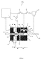
- FIG. 1 shows a schematic configuration of the combined torch type plasma spraying apparatus 100a, which is illustrated as one embodiment of the present invention.
- a main torch 1 includes a main anode 3, a main mantle 4 that surrounds the main anode 3, an insulator 27 that insulates the main anode 3 and the main mantle 4 from each other, and the like.
- the main anode 3 is formed by a material excellent in electrical conductivity, for example, a metal such as copper.
- the main anode 3 includes a material feed-in pipe 19 having a spraying material discharge hole at the tip center of the central axis.
- the main anode 3 is concentrically held with the main mantle 4 by the insulator 27.
- the main mantle 4 includes an opening part (nozzle part) 4a at the tip part and a tapered part 4b provided between the opening part 4a and the insulator 27.
- the tapered part 4b is provided with a gas introducing hole 4c that introduces an inert gas or the like and forms a swirl gas flow.
- the insulator 27 includes a main plasma gas introducing port 5 that introduces a main plasma gas 6 and a swirl flow forming means 50 for the introduced main plasma gas 6.
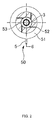
- the main plasma gas 6 is introduced into an annular gas chamber 51, passes through four swirl flow forming holes 52, and flows toward the opening part 4a of the main mantle 4 so as to rotate along an inner wall 53 (a space between the inner wall 53 and the main anode 3) of the insulator 27.
- one swirl flow forming hole 52 mentioned above may be arranged or a plurality of swirl flow forming holes 52 may be arranged, and when the plurality of swirl flow forming holes are arranged, it is preferable that those swirl flow forming holes are uniformly arranged about the central axis.
- a positive terminal of a main power source 7 is connected to the main anode 3, and a negative terminal of the main power source 7 is connected to the main mantle 4 through a switching means 8.
- the auxiliary torch 2 includes an auxiliary cathode (auxiliary torch activating electrode) 10, an auxiliary mantle 11 that surrounds the auxiliary cathode 10, an insulator 28 that insulates the auxiliary cathode 10 and the auxiliary mantle 11 from each other, and the like.
- the central axis of the auxiliary torch 2, that is, the central axis of the auxiliary cathode 10 is arranged so as to intersect with the central axis of the main torch 1, that is, the central axis of the main anode 3, in front of the main anode 3 and the auxiliary cathode 10.
- the auxiliary cathode 10 is formed of a material having a high melting point, for example, such as tungsten.
- the auxiliary cathode 10 is concentrically held with the auxiliary mantle 11 by the insulator 28.
- the auxiliary mantle 11 includes a hole 11a at the tip part.
- the insulator 28 includes an auxiliary plasma gas introducing port 12 that introduces an auxiliary plasma gas 13 and a swirl flow forming means 50 similar to that in the insulator 27 of the main torch 1.
- a positive terminal of an auxiliary power source 14 is connected to the auxiliary mantle 11, and a negative terminal of the auxiliary power source 14 is connected to the auxiliary cathode 10 through a switching means 15 and is also connected to the negative terminal of the main power source 7 through a switching means 9.
- a method of plasma spraying a spraying material for example, a conductive material such as metal, an insulating material such as ceramics, and the like, the same applies to the following
- a spraying material for example, a conductive material such as metal, an insulating material such as ceramics, and the like, the same applies to the following
- An inert gas such as argon, helium capable of turning into plasma is introduced into the main torch 1 as the main plasma gas 6 from the main plasma gas introducing port 5, and a swirl flow of the main plasma gas 6 is formed. Further, in a state in which the switching means 9 is opened and the switching means 8 is closed, a high frequency voltage is applied between the main anode 3 and the main mantle 4 from the main power source 7. As a result, a main plasma arc 16 directed from the tip of the main anode 3 to the opening part 4a of the main mantle 4 is formed. This allows the main plasma gas 6 to be heated and become plasma, and then this plasma is released from the opening part 4a of the main mantle 4.
- argon, helium capable of turning into plasma
- the inert gas such as argon, helium capable of turning into plasma is introduced into the auxiliary torch 2 from the auxiliary plasma gas introducing port 12 as the auxiliary plasma gas 13, and the swirl flow of the auxiliary plasma gas 13 is formed.
- a high frequency voltage is applied between the auxiliary cathode 10 and the auxiliary mantle 11 from the auxiliary power source 14.
- an auxiliary plasma arc 17 directed from the tip 10a of the auxiliary cathode 10 toward the hole 11a of the auxiliary mantle 24 is formed. This allows the auxiliary plasma gas 13 to be heated and become plasma, and then this plasma is released from the hole 11a of the auxiliary mantle 11.
- a plasma flame 23 can be formed substantially coaxially with the main torch 1 as shown in FIG. 1 .
- the spraying material 20 discharged through the spraying material discharge hole from the material feed-in pipe 19 is supplied to the axial center of the plasma 18 to be formed on the central axis of the main anode 3 by the main anode 3 and the auxiliary cathode 10, and is melted by the plasma flame 23.
- an inert gas or the like for example, an inert gas such as an argon gas, and an active gas such as air or an oxygen gas
- the gas introducing hole 4c provided in the tapered part 4b of the main mantle 4 to form the swirl gas flow.
- the gas introducing hole 4c is provided in the tapered part 4b of the main mantle 4.
- the gas introducing hole 4c may be provided on an inlet side of the opening part 4a of the main mantle 4 and may be provided in the tapered part 4b of the main mantle 4 and on the inlet side of the opening part 4a, respectively.
- the main mantle 4 may be constituted by a porous metallic material M so as to form on the whole inner surface of the mantle the gas flow for preventing the adhesion of the spraying material, and the gas supplied from the gas introducing port 4d provided in the main mantle 4 may be ejected only in the inside direction of the main mantle 4 through micropores in the porous metallic material M as shown by the arrow in the FIG. 5 .
- a melt 21 which is the melted spraying material 20 travels toward a base material 25 with the plasma flame 23. Only plasma 18 is separated immediately in front of the base material 25 by a plasma separation means 22 provided on a connecting pipe 26, and the melt 21 is sprayed on the base material 25. Thus, a coating 24 of a dense spraying material 20 having little pores can be efficiently formed.
- a plasma spraying apparatus including a main torch and two auxiliary torches is described as a plasma spraying apparatus of the present invention.
- a twin-cathode type plasma spraying apparatus 100b is described in which the electrode in the main torch is a main anode, and the electrodes in the auxiliary torches are auxiliary cathodes.
- the plasma spraying apparatus including a main torch and two auxiliary torches may be a twin-anode type plasma spraying apparatus in which the electrode in the main torch is a main cathode and the electrodes in the auxiliary torches are auxiliary anodes.
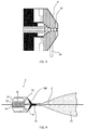
- FIG. 2 shows a schematic configuration of the twin-cathode type plasma spraying apparatus 100b, which is illustrated as another embodiment of the present invention.
- the positive terminal of the main power source 7 is connected the auxiliary mantle 11 through the main anode 3 and a switching means 55, and the negative terminal of the main power source 7 is connected to the main mantle 4 through the switching means 8.
- the positive terminal of the auxiliary torch 2 from an auxiliary power source 42 is connected to the auxiliary mantle 11 through a switching means 45, and the negative terminal of the auxiliary torch 2 from the auxiliary power source 42 is connected to the auxiliary cathode 10 through a switching means 46 and is also connected to the negative terminal of the main power source 7 through the switching means 9.
- auxiliary torch 39 is arranged at a position opposing to the auxiliary torch 2 with respect to the central axis of the main torch.
- the auxiliary torch 39 includes an auxiliary cathode (auxiliary torch activating electrode) 40, an auxiliary mantle 41 that surrounds the auxiliary cathode 40, an insulator 47 that insulates the auxiliary cathode 40 and the auxiliary mantle 41 from each other, and the like.
- the central axis of the auxiliary torch 39 that is, the central axis of the auxiliary cathode 40 is arranged so as to intersect with the central axis of the main torch 1, that is, the central axis of the main anode 3 in front of the main anode 3 and the auxiliary cathode 40.
- the auxiliary cathode 40 is formed of a material having a high melting point, for example, such as tungsten.
- the auxiliary cathode 40 is concentrically held with the auxiliary mantle 41 by the insulator 48.
- the auxiliary mantle 41 includes a hole 41a at the tip part.
- the insulator 47 includes an auxiliary plasma gas introducing port 48 that introduces an auxiliary plasma gas 49 and a swirl flow forming means 50 similar to that in the insulator 27 of the main torch 1.
- the positive terminal of the auxiliary torch 39 from the auxiliary power source 42 is connected to the auxiliary mantle 41 through a switching means 44, and the negative terminal of the auxiliary torch 39 from the auxiliary power source 14 is connected to the auxiliary cathode 40 through a switching means 43 and is also connected to the negative terminal of the main power source 7 through the switching means 9 and 46.
- the inert gas such as argon, helium capable of turning into plasma is introduced into the main torch 1 from the main plasma gas introducing port 5 as the main plasma gas 6 to form the swirl flow of the main plasma gas 6. Further, in a state where the switching means 9 is opened and the switching means 8 is closed, a high frequency voltage is applied between the main anode 3 and the main mantle 4 from main power source 7. As a result, the main plasma arc 16 directed from the tip of the main anode 3 toward the opening part 4a of the main mantle 4 is formed. This allows the main plasma gas 6 to be heated and become plasma, and then this plasma is released from the opening part 4a of the main mantle 4.
- argon, helium capable of turning into plasma
- the inert gas such as argon, helium capable of turning into plasma is introduced as the auxiliary plasma gas 13 from the auxiliary plasma gas introducing port 12 into the auxiliary torch 2 to form the swirl flow of the auxiliary plasma gas 13.
- a high frequency voltage is applied between the auxiliary cathode 10 and the auxiliary mantle 11 from the auxiliary power source 42 in a state where the switching means 43, 44 are opened and the switching means 45, 46 are closed.
- an auxiliary plasma arc 17 directed from the tip 10a of the auxiliary cathode 10 toward the hole 11a of the auxiliary mantle 24 is formed. This allows the auxiliary plasma gas 13 to be heated and become plasma, and then this plasma is released from the hole 11a of the auxiliary mantle 11.
- the inert gas such as argon, helium capable of turning into plasma is introduced as an auxiliary plasma gas 49 from an auxiliary plasma gas introducing port 48 into the auxiliary torch 39 to form the swirl flow of the auxiliary plasma gas 49.
- a high frequency voltage is applied between the auxiliary cathode 40 and the auxiliary mantle 41 from the auxiliary power source 42 in a state where the switching means 43, 44 are closed.
- an auxiliary plasma arc 56 directed from a tip 40a of the auxiliary cathode 40 toward a hole 41a of the auxiliary mantle 41 is formed. This allows the auxiliary plasma gas 49 to be heated and become plasma, and then this plasma is released from the hole 41a of the auxiliary mantle 41.
- the plasma released from the hole 41a of the auxiliary mantle 41 intersects with the hairpin-like plasma 18 that reaches the anode spot of the main anode 3 from the tip part 10a of the auxiliary cathode 10.
- the spraying material 20 discharged from the material feed-in pipe 19 through the spraying material discharge hole is supplied to the axial center of the plasma 18 to be formed on the central axis of the main anode 3 by the main anode 3 and the auxiliary cathode 10, and is melted by the plasma flame 23.
- a gas for example, the inert gas such as an argon gas, the active gas such as air or an oxygen gas
- the gas introducing hole 4c provided in the tapered part 4b of the main mantle 4 to form a swirl gas flow, and this makes it possible to prevent the spraying material 20 from adhering to the opening part 4a in the main mantle 4 and on the inner wall of the tip part of the tapered part 4b. Further, since the adhesion of the spraying material 20 can be prevented, the spraying material 20 can be efficiently melted.
- the gas introducing hole 4c is provided in the tapered part 4b of the main mantle 4.
- the gas introducing hole 4c may be provided on the inlet side of the opening part 4a of the main mantle 4 or may be provided in the tapered part 4b of the main mantle 4 and on the inlet side of the opening part 4a, respectively.
- the main mantle 4 may be constituted by the porous metallic material M so as to form on the whole inner surface of the mantle the gas flow for preventing the adhesion of the spraying material, and the gas supplied from the gas introducing port 4d provided in the main mantle 4 may be ejected only in the inside direction of the main mantle 4 through micropores in the porous metallic material M.
- the melt 21 which is the melted spraying material 20 travels toward the base material 25 together with the plasma flame 23. Only plasma 18 is separated immediately in front of the base material 25 by the plasma separation means 22 provided on the connecting pipe 26, the melt 21 is sprayed on the base material 25, and thus, the coating 24 of the dense spraying material 20 having little pores can be efficiently formed.
- auxiliary torches are provided in the plasma spraying apparatus 100b.
- three auxiliary torches may be provided.
- these auxiliary torches are arranged so that their central axes intersect with one another in front of the main anode 3 and at one point of the central axis outside of the main torch 1, and it is more preferable that these auxiliary torches are arranged uniformly on an outer circumference of a circle with the intersecting point as a center and perpendicular to the central axis.
- each of the auxiliary torches is arranged such that the central axis of each of the auxiliary torches perpendicularly intersects with the central axis of the main torch 1 at the above-mentioned intersecting point.
- one or a plurality of electrically-insulated floating electrodes may be provided on the tip side of the opening part 4a of the main mantle 4 in the above-mentioned plasma spraying apparatuses 100a, 100b.
- a thermal pinch effect is enhanced and high temperature plasma can be formed, so that it becomes possible to efficiently melt the spraying material 20.
- a hole through which a gas is introduced may be further provided in a part in which the above-mentioned floating electrodes are arranged to introduce the inert gas (for example, an argon gas or the like) or the active gas (for example, air, oxygen or the like).
- one or a plurality of electrically-insulated floating electrodes may be provided on the tip side of the opening part (holes 11a, 41a) of the auxiliary mantles 11, 41. Further, a hole through which a gas is introduced may be further provided in a part in which the floating electrode is arranged to introduce the inert gas (for example, an argon gas or the like) or the active gas (for example, air, oxygen or the like). This enhances a thermal pinch effect, and it becomes possible to form higher temperature plasma.
- the inert gas for example, an argon gas or the like
- the active gas for example, air, oxygen or the like
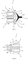
- FIG. 3 shows a schematic configuration of the integrated plasma spraying apparatus 100c that is illustrated as another embodiment of the present invention.
- the main torch 1 includes a main anode 3, a main mantle 4 that surrounds the main anode 3, an insulator 27 that insulates the main anode 3 and the main mantle 4 from each other, and the like.
- the main anode 3 is formed of a material excellent in electrical conductivity, for example, a metal such as copper.
- the main anode 3 includes a material feed-in pipe 19 having a spraying material discharge hole at the tip center of the central axis.
- the main anode 3 is concentrically held with the main mantle 4 by the insulator 27.
- the main mantle 4 includes an opening part (nozzle part) 4a of the tip part and the tapered part 4b provided between the opening part 4a and the insulator 27.
- an electrically-insulated insulator 60 is provided in the opening part 4a.
- an inert gas introducing hole 4c that introduces the inert gas to form the swirl gas flow is provided on the downstream side of the opening part 4a.
- the auxiliary torch 2 is provided on the upstream side of the opening part 4a.
- the main mantle 4 may be constituted by the porous metallic material M so as to form on the whole inner surface of the mantle the gas flow for preventing the adhesion of the spraying material, and the gas supplied from the gas introducing port 4d provided to the main mantle 4 may be ejected only in the inside direction of the main mantle 4 through micropores in the porous metallic material M.
- the auxiliary torch 2 includes an auxiliary cathode (auxiliary torch activating electrode) 10, an auxiliary mantle 11 that surrounds the auxiliary cathode 10, an insulator 28 that insulates the auxiliary cathode 10 and the auxiliary mantle 11 from each other, and the like.
- the central axis of the auxiliary torch 2, that is, the central axis of the auxiliary cathode 10 is arranged so as to intersect with the central axis of the main torch 1, that is, the central axis of the main anode 3 in front of the main anode 3 and the auxiliary cathode 10.
- the auxiliary cathode 10 is formed of a material having a high melting point, for example, such as tungsten.
- the auxiliary cathode 10 is concentrically held with the auxiliary mantle 11 by the insulator 28.
- the auxiliary mantle 11 includes a hole at the tip part.
- the insulator 28 includes an auxiliary plasma gas introducing port 12 that introduces the auxiliary plasma gas 13, and a swirl flow forming means 50 similar to that in the insulator 27 of the main torch 1.
- the insulator 27 includes a main plasma gas introducing port 5 that introduces the main plasma gas 6, and a swirl flow forming means 50 of the main plasma gas 6.
- the positive terminal of the main power source 7 is connected to the main anode 3, and the negative terminal of the main power source 7 is connected to the tapered part 4b of the main mantle 4 through the switching means 8.
- the positive terminal of the auxiliary power source 14 is connected to the auxiliary mantle 11, and the negative terminal of the auxiliary power source 14 is connected to the auxiliary cathode 10 through the switching means 15 and is also connected to the negative terminal of the main power source 7 through the switching means 9.
- the inert gas such as argon, helium capable of turning into plasma is introduced as a main plasma gas 6 from the main plasma gas introducing port 5 into the main torch 1 to form the swirl flow of the main plasma gas 6. Further, a high frequency voltage is applied between the main anode 3 and the tapered part 4b of the main mantle 4 from the main power source 7 in a state where the switching means 9 is opened and the switching means 8 is closed. As a result, a main plasma arc that is directed from the tip of the main anode 3 toward the opening part 4a of the main mantle 4 is formed, thereby heating the main plasma gas 6.
- argon, helium capable of turning into plasma
- the inert gas such as argon, helium capable of turning into plasma is introduced as an auxiliary plasma gas 13 into the auxiliary torch 2 from the auxiliary plasma gas introducing port 12 to form the swirl flow of the auxiliary plasma gas 13.
- a high frequency voltage is applied between the auxiliary cathode 10 and the auxiliary mantle 11 from the auxiliary power source 14 in a state where the switching means 15 is closed.
- the auxiliary plasma arc that is directed from the tip 10a of the auxiliary cathode 10 toward the hole 11a of the auxiliary mantle 24 is formed, thereby heating the auxiliary plasma gas 13.
- the plasma flame 23 can be formed substantially coaxially with the main torch 1 as shown in FIG. 4 .
- the spraying material 20 discharged from the material feed-in pipe 19 through the spraying material discharge hole is supplied to the axial center of plasma to be formed on the central axis of the main anode 3 by the main anode 3 and the auxiliary cathode 10, and is melted by the plasma flame 23.
- the auxiliary torch 2 is embedded in the upstream (tip) of the insulator 60 of the main mantle 4 in the main torch 1, and thus the plasma arc is confined in the main torch 1 to enhance a thermal pinch effect, thereby allowing an input of the plasma arc to be increased.
- a gas for example, the inert gas such as an argon gas, the active gas such as air or an oxygen gas
- the inert gas introducing hole 4c provided on the inlet side of the opening part 4a of the main mantle 4 to form the swirl gas flow, and this can prevent the spraying material 20 from adhering to the inner wall of the opening part 4a in the main mantle 4.
- the spraying material 20 can be efficiently melted.
- the melt which is the melted spraying material 20 is splayed on the base material 25, and a coating of the dense spraying material 20 having little pores can be efficiently formed.
- the gas introducing hole 4c is provided on the inlet side of the opening part 4a of the main mantle 4.
- the gas introducing hole 4c may be provided in the tapered part 4b of the main mantle 4 and may be provided in the tapered part 4b and on the inlet side of the opening part 4a in the main mantle 4, respectively.
- the main mantle 4 may be constituted by porous metallic material M so as to form on the whole inner surface the gas flow for preventing the adhesion of the spraying material, and the gas supplied from the gas introducing port 4d provided in the main mantle 4 may be ejected only in the inside direction of the main mantle 4 through micropores in the porous metallic material M.
- FIGs. 6 to 8 show schematic configurations of the tip part of the main anode 3, which are described as preferred embodiments of the present invention.
- the main anode 3 is provided with a cooling passage 3A that circulates cooling water W, between the outer peripheral surface of the main anode 3 and the material feed-in pipe 19.
- a tip surface 3f of the main anode 3 is formed in an inwardly protruding shape on the central axis (for example, an inwardly protruding truncated cone shape or the like).
- a spraying material discharge hole 19P that is an outlet of the material feed-in pipe 19 is arranged at the center of the tip surface 3f of the main anode 3, and a protruding part (edge of the tip) of the outer periphery of the tip of the main anode 3 is an anode spot 3P.
- the position of the anode spot 3P of the main anode 3 is provided to be closer to the cathode spot than the position of the spraying material discharge hole 19P of the material feed-in pipe 19, so that when the spraying material 20 is supplied, the spraying material 20 and the anode spot of the plasma (plasma arc) 18 do not interfere with each other. Further, since the axial center of the plasma 18 is placed on the same straight line as the central axis C of the main torch 1, the spraying material 20 can be supplied to a high temperature part of the plasma 18 and can be substantially completely melted.
- the spraying material 20 to be supplied powders of a conductive material such as metal, an insulating material such as ceramics, or the like can be used.
- a conductive material such as metal
- an insulating material such as ceramics, or the like
- the material feed-in pipe 19 is produced by a material such as ceramics having heat resistance and insulating properties.
- the configuration of the tip part of the main anode 3 is not particularly limited as long as the anode spot 3P is located on the outer circumferential side of the spraying material discharge hole 19P and is arranged so as not to allow the anode spot 3P and the spraying material discharge hole 19P to interfere with each other. Further, as shown in FIG.
- the tip part of the main anode 3 preferably includes one or a plurality of gas ejection holes 31 for preventing the adhesion of the spraying material, which penetrates from the outer peripheral face at a position where the spraying material discharge hole 19P and the anode spot 3P do not interfere with each other, for example, at a position between the spraying material discharge hole 19P and the anode spot 3P on the tip surface 3f.
- the tip part of the main anode 3 is formed in a truncated cone shape as shown in FIG. 8 , and the above-mentioned gas ejection hole 31 is provided so as to penetrate from the outer peripheral face at the position where the spraying material discharge hole 19P and the anode spot 3P on the tip surface 3f do not interfere with each other.
Landscapes
- Physics & Mathematics (AREA)
- Engineering & Computer Science (AREA)
- Plasma & Fusion (AREA)
- Spectroscopy & Molecular Physics (AREA)
- Chemical & Material Sciences (AREA)
- Electromagnetism (AREA)
- Chemical Kinetics & Catalysis (AREA)
- Materials Engineering (AREA)
- Mechanical Engineering (AREA)
- Metallurgy (AREA)
- Organic Chemistry (AREA)
- Nozzles (AREA)
- Coating By Spraying Or Casting (AREA)
- Plasma Technology (AREA)
Abstract
Description
- The present invention relates to a plasma spraying apparatus that can supply a spraying material to an axial center of plasma to be formed on a center axis of an electrode of a main torch by electrodes of the main torch and an auxiliary torch, and that can suppress adhesion of a spraying material on the inner wall of an opening part in a mantle of the main torch.
- Conventionally, in a plasma spraying apparatus that comprises a main torch and an auxiliary torch having an electrode, a mantle that surrounds the electrode, and an insulator that insulates the electrode and the mantle from each other and includes a plasma gas introducing port, a plasma spraying appartus has been developed in which a material discharge hole is provided at a tip center of the central axis of the electrode of the main torch, the spraying material is supplied to the center of the plasma axis from the material discharge hole, the spraying material is efficiently melted, and a dense film of the spraying material having little pores can be efficiently formed without being welded to the main torch (for example, see
Japanese Patent No. 3733461 Japanese Patent No. 4804854 Japanese Patent Application Laid-open Publication No. 2010-110669 - However, even in the plasma spraying apparatus as stated above, it has been found that the spraying material adheres to the inner wall of the opening part in the mantle of the main torch, and this may cause a blockage of the opening part.
- The present invention has been made in view of the above problems, and this invention aims to provide a plasma spraying apparatus that can supply the spraying material to the axial center of the plasma to be formed on the central axis of the electrode of the main torch by the electrodes of the main torch and the auxiliary torch and that can suppress the adhesion of the spraying material on the inner wall of the opening part in the mantle of the main torch.
- As a result of the diligent research by the present inventors for solving the above problems, it has been found that a gas introducing part is provided to an inlet of the opening part in the mantle of the main torch or in the tapered part between the opening part and the insulator to introduce gas, thereby preventing the spraying material from adhering to the inner wall of the opening part in the mantle of the main torch, and this leads to accomplish the present invention.
- That is, the present invention is:
- (1) a plasma spraying apparatus, including:
- a main torch including a first electrode having a spraying material discharge hole at a tip center of a central axis, a first mantle that surrounds the first electrode, and a first insulator that insulates the first electrode and the first mantle from each other and has a first plasma gas introducing port; and
- an auxiliary torch including a second electrode, a second mantle that surrounds the second electrode, and a second insulator that insulates the second electrode and the second mantle from each other and has a second plasma gas introducing port, the auxiliary torch having a central axis that intersects with a central axis of the main torch,
- a spraying material supplied from the spraying material discharge hole to an axial center of plasma to be formed on the central axis of the first electrode by the first electrode and the second electrode being melted, the melted spraying material being sprayed on a base material to form a coating of the spraying material,
- the first mantle including an opening part and a tapered part provided between the opening part and the first insulator, and
- the first mantle including, on an inlet side of the opening part and/or the tapered part, a gas introducing part that introduces gas;
- (2) the plasma spraying apparatus according to the above-stated (1), wherein
the first electrode is an anode, and the second electrode is a cathode; - (3) the plasma spraying apparatus according to the above-state (2), wherein
the opening part includes a third insulator at the center, and
the auxiliary torch is provided closer to an outlet side than the third insulator of the opening part; - (4) the plasma spraying apparatus according to the above-stated (2), wherein
the main torch and the auxiliary torch are arranged so that a plasma arc is formed in the outside; - (5) the plasma spraying apparatus according to the above-stated 4, further comprising a plurality of auxiliary torches, wherein
the plurality of auxiliary torches are arranged so that central axes of the plurality of auxiliary torches are respectively intersected at one point of the central axis of the main torch outside the main torch; - (6) the plasma spraying apparatus according to any one of the above-stated (3) to (5), wherein
an anode spot of the first electrode and the spraying material discharge hole are configured not to interfere with one another - (7) the plasma spraying apparatus according to any one of the above-stated (3) to (5), wherein
a tip surface of the first electrode is formed in an inwardly protruding shape; - (8) the plasma spraying apparatus according to any one of the above-stated (3) to (7), wherein
a tip of the first electrode is provided with a gas ejection hole for preventing adhesion of the spraying material; - (9) the plasma spraying apparatus according to any one of the above-stated (3) to (8), wherein
the gas introducing part of the first mantle includes, on an inlet side of the opening part and/or the tapered part, a gas ejection hole that introduces gas; - (10) the plasma spraying apparatus according to any one of the above-stated (3) to (8), wherein
the gas introducing part of the first mantle includes a gas ejection hole through which gas is ejected to have a circumferential velocity component with respect to the central axis so that the gas is allowed to be a swirl flow inside the opening part and the tapered part; - (11) the plasma spraying apparatus according to any one of the above-stated (3) to (8), wherein
the first mantle is constituted by a porous metal, and the gas introducing part is configured such that gas introduced from the outside is ejected through holes in the porous metal only in an inside direction of the first mantle; and the like. - According to the present invention, there can be provided a plasma spraying apparatus that can supply the spraying material to the axial center of the plasma to be formed on the central axis of the electrode of the main torch by the electrodes of the main torch and auxiliary torch, and that can suppress the adhesion of the spraying material on the inner wall of the opening part in the mantle of the main torch.
-
- [
FIG. 1] FIG. 1 shows a schematic configuration of a combined torch typeplasma spraying apparatus 100a, which is illustrated as one embodiment of the present invention. - [
FIG. 2] FIG. 2 shows a cross section taken along line III-III' inFIG. 1 , which is illustrated as one embodiment of the present invention. - [
FIG. 3] FIG. 3 shows a schematic configuration of a twin-cathode typeplasma spraying apparatus 100b, which is illustrated as another embodiment of the present invention. - [
FIG. 4] FIG. 4 shows a schematic configuration of an integratedplasma spraying apparatus 100c of a main torch and an auxiliary torch, which is illustrated as another embodiment of the present invention. - [
FIG. 5] FIG. 5 shows a schematic configuration of the mantle, which is illustrated as one preferred embodiment of the present invention. - [
FIG. 6] FIG. 6 shows a schematic configuration of the tip part of the main anode, which is illustrated as one preferred embodiment of the present invention. - [
FIG. 7] FIG. 7 shows a schematic configuration of the tip part of the main anode, which is illustrated as one further preferred embodiment of the present invention. - [
FIG. 8] FIG. 8 shows a schematic configuration of the tip part of the main anode, which is illustrated as one particularly preferred embodiment of the present invention. - Preferred embodiments of the plasma spraying apparatus according to the present invention are described in detail below with reference to the accompanying drawings. Note that, objects, features, advantages and ideas of the present invention are apparent to those skilled in the art from the description of the present specification and those skilled in the art can easily reproduce the present invention from the description of the present specification. Embodiments of the invention and drawings described below show preferred embodiments of the present invention and are shown for illustrative or explanatory purposes, and thus the present invention is not limited thereto. It is apparent to those skilled in the art that various modifications may be made based on the description of the present specification within the spirit and the scope of the present invention disclosed herein.
- First, a combined torch type plasma spraying apparatus including a main torch and an auxiliary torch is described as a plasma spraying apparatus of the present invention. Note that, in the present embodiment, as a preferred example of the combined torch type plasma spraying apparatus including the main torch and the auxiliary torch, a combined torch type
plasma spraying apparatus 100a is described in which an electrode in the main torch is a main anode and an electrode in the auxiliary torch is an auxiliary electrode (cathode). However, the plasma spraying apparatus including the main torch and the auxiliary torch may be a combined torch type plasma spraying apparatus in which an electrode in the main torch is a main cathode and an electrode in the auxiliary torch is an auxiliary anode.FIG. 1 shows a schematic configuration of the combined torch typeplasma spraying apparatus 100a, which is illustrated as one embodiment of the present invention. - A
main torch 1 includes amain anode 3, amain mantle 4 that surrounds themain anode 3, aninsulator 27 that insulates themain anode 3 and themain mantle 4 from each other, and the like. - The
main anode 3 is formed by a material excellent in electrical conductivity, for example, a metal such as copper. Themain anode 3 includes a material feed-inpipe 19 having a spraying material discharge hole at the tip center of the central axis. Themain anode 3 is concentrically held with themain mantle 4 by theinsulator 27. - The
main mantle 4 includes an opening part (nozzle part) 4a at the tip part and atapered part 4b provided between theopening part 4a and theinsulator 27. Thetapered part 4b is provided with agas introducing hole 4c that introduces an inert gas or the like and forms a swirl gas flow. - The
insulator 27 includes a main plasmagas introducing port 5 that introduces amain plasma gas 6 and a swirl flow forming means 50 for the introducedmain plasma gas 6. As shown inFIG. 2 , themain plasma gas 6 is introduced into anannular gas chamber 51, passes through four swirlflow forming holes 52, and flows toward theopening part 4a of themain mantle 4 so as to rotate along an inner wall 53 (a space between theinner wall 53 and the main anode 3) of theinsulator 27. Note that, one swirlflow forming hole 52 mentioned above may be arranged or a plurality of swirlflow forming holes 52 may be arranged, and when the plurality of swirl flow forming holes are arranged, it is preferable that those swirl flow forming holes are uniformly arranged about the central axis. - As shown in
FIG. 1 , a positive terminal of amain power source 7 is connected to themain anode 3, and a negative terminal of themain power source 7 is connected to themain mantle 4 through a switching means 8. - The
auxiliary torch 2 includes an auxiliary cathode (auxiliary torch activating electrode) 10, anauxiliary mantle 11 that surrounds theauxiliary cathode 10, aninsulator 28 that insulates theauxiliary cathode 10 and theauxiliary mantle 11 from each other, and the like. The central axis of theauxiliary torch 2, that is, the central axis of theauxiliary cathode 10 is arranged so as to intersect with the central axis of themain torch 1, that is, the central axis of themain anode 3, in front of themain anode 3 and theauxiliary cathode 10. - The
auxiliary cathode 10 is formed of a material having a high melting point, for example, such as tungsten. Theauxiliary cathode 10 is concentrically held with theauxiliary mantle 11 by theinsulator 28. - The
auxiliary mantle 11 includes ahole 11a at the tip part. Theinsulator 28 includes an auxiliary plasmagas introducing port 12 that introduces anauxiliary plasma gas 13 and a swirl flow forming means 50 similar to that in theinsulator 27 of themain torch 1. - A positive terminal of an
auxiliary power source 14 is connected to theauxiliary mantle 11, and a negative terminal of theauxiliary power source 14 is connected to theauxiliary cathode 10 through a switching means 15 and is also connected to the negative terminal of themain power source 7 through a switching means 9. - Next, a method of plasma spraying a spraying material (for example, a conductive material such as metal, an insulating material such as ceramics, and the like, the same applies to the following) by the use of the combined torch type
plasma spraying apparatus 100a is described. - An inert gas such as argon, helium capable of turning into plasma is introduced into the
main torch 1 as themain plasma gas 6 from the main plasmagas introducing port 5, and a swirl flow of themain plasma gas 6 is formed. Further, in a state in which the switching means 9 is opened and the switching means 8 is closed, a high frequency voltage is applied between themain anode 3 and themain mantle 4 from themain power source 7. As a result, amain plasma arc 16 directed from the tip of themain anode 3 to theopening part 4a of themain mantle 4 is formed. This allows themain plasma gas 6 to be heated and become plasma, and then this plasma is released from theopening part 4a of themain mantle 4. - In addition, the inert gas such as argon, helium capable of turning into plasma is introduced into the
auxiliary torch 2 from the auxiliary plasmagas introducing port 12 as theauxiliary plasma gas 13, and the swirl flow of theauxiliary plasma gas 13 is formed. Further, in a state where the switching means 15 is closed, a high frequency voltage is applied between theauxiliary cathode 10 and theauxiliary mantle 11 from theauxiliary power source 14. As a result, anauxiliary plasma arc 17 directed from thetip 10a of theauxiliary cathode 10 toward thehole 11a of theauxiliary mantle 24 is formed. This allows theauxiliary plasma gas 13 to be heated and become plasma, and then this plasma is released from thehole 11a of theauxiliary mantle 11. - Since the central axis of the
main anode 3 and the central axis of theauxiliary cathode 10 are intersected with each other outside themain torch 1 and theauxiliary torch 2 in front of themain anode 3 and theauxiliary cathode 10, when the switching means 9 is closed and the switching means 8, 15 are opened, a conductive path using a hairpin-like plasma 18 that reaches an anode spot of themain anode 3 from thetip part 10a of theauxiliary cathode 10 is formed. - In this case, by appropriately setting the configuration of the
main torch 1 and the amount of themain plasma gas 6 to be supplied, and the configuration of theauxiliary torch 2 and the amount of theauxiliary plasma gas 13 to be supplied to theauxiliary torch 2, aplasma flame 23 can be formed substantially coaxially with themain torch 1 as shown inFIG. 1 . - The spraying
material 20 discharged through the spraying material discharge hole from the material feed-inpipe 19 is supplied to the axial center of theplasma 18 to be formed on the central axis of themain anode 3 by themain anode 3 and theauxiliary cathode 10, and is melted by theplasma flame 23. In the embodiment of the present invention, when the sprayingmaterial 20 is discharged from the spraying material discharge hole, an inert gas or the like (for example, an inert gas such as an argon gas, and an active gas such as air or an oxygen gas) is introduced by thegas introducing hole 4c provided in thetapered part 4b of themain mantle 4 to form the swirl gas flow. In this way, it becomes possible to uniformly and axisymmetrically generate negative pressure gradient toward the central axis from the inner wall of themain mantle 4 in an inner space of themain mantle 4 as compared to the case of directly ejecting an inert gas to the central axis from the inert gas ejection hole. This allows to focus the plasma stably and uniformly in the inner space of the mantle, while preventing the adhesion of the sprayingmaterial 20 even to a part away from the inert gas ejection hole such as the inner wall of theopening part 4a and the tip part of thetapered part 4b in themain mantle 4. - Further, since the adhesion of the spraying
material 20 can be prevented, the sprayingmaterial 20 can be efficiently melted. Note that, in the present embodiment, thegas introducing hole 4c is provided in thetapered part 4b of themain mantle 4. However, thegas introducing hole 4c may be provided on an inlet side of theopening part 4a of themain mantle 4 and may be provided in thetapered part 4b of themain mantle 4 and on the inlet side of theopening part 4a, respectively. - Further, as shown in
FIG. 5 , instead of providing thegas ejection hole 4c for forming the swirl flow, themain mantle 4 may be constituted by a porous metallic material M so as to form on the whole inner surface of the mantle the gas flow for preventing the adhesion of the spraying material, and the gas supplied from thegas introducing port 4d provided in themain mantle 4 may be ejected only in the inside direction of themain mantle 4 through micropores in the porous metallic material M as shown by the arrow in theFIG. 5 . - A
melt 21 which is the melted sprayingmaterial 20 travels toward abase material 25 with theplasma flame 23. Onlyplasma 18 is separated immediately in front of thebase material 25 by a plasma separation means 22 provided on a connectingpipe 26, and themelt 21 is sprayed on thebase material 25. Thus, acoating 24 of adense spraying material 20 having little pores can be efficiently formed. - Next, a plasma spraying apparatus including a main torch and two auxiliary torches is described as a plasma spraying apparatus of the present invention. Note that, in the present embodiment, as a preferred example of the plasma spraying apparatus including a main torch and two auxiliary torches, a twin-cathode type
plasma spraying apparatus 100b is described in which the electrode in the main torch is a main anode, and the electrodes in the auxiliary torches are auxiliary cathodes. However, the plasma spraying apparatus including a main torch and two auxiliary torches may be a twin-anode type plasma spraying apparatus in which the electrode in the main torch is a main cathode and the electrodes in the auxiliary torches are auxiliary anodes.FIG. 2 shows a schematic configuration of the twin-cathode typeplasma spraying apparatus 100b, which is illustrated as another embodiment of the present invention. - Since the configuration of the
main torch 1 and theauxiliary torch 2 included in the twin-cathode typeplasma spraying apparatus 100b is identical to that of themain torch 1 and theauxiliary torch 2 in the combined torch typeplasma spraying apparatus 100a, the description thereof will be omitted herein. - Note that, the positive terminal of the
main power source 7 is connected theauxiliary mantle 11 through themain anode 3 and a switching means 55, and the negative terminal of themain power source 7 is connected to themain mantle 4 through the switching means 8. Further, the positive terminal of theauxiliary torch 2 from anauxiliary power source 42 is connected to theauxiliary mantle 11 through a switching means 45, and the negative terminal of theauxiliary torch 2 from theauxiliary power source 42 is connected to theauxiliary cathode 10 through a switching means 46 and is also connected to the negative terminal of themain power source 7 through the switching means 9. - In the present embodiment, another
auxiliary torch 39 is arranged at a position opposing to theauxiliary torch 2 with respect to the central axis of the main torch. Theauxiliary torch 39 includes an auxiliary cathode (auxiliary torch activating electrode) 40, anauxiliary mantle 41 that surrounds theauxiliary cathode 40, aninsulator 47 that insulates theauxiliary cathode 40 and theauxiliary mantle 41 from each other, and the like. The central axis of theauxiliary torch 39, that is, the central axis of theauxiliary cathode 40 is arranged so as to intersect with the central axis of themain torch 1, that is, the central axis of themain anode 3 in front of themain anode 3 and theauxiliary cathode 40. - The
auxiliary cathode 40 is formed of a material having a high melting point, for example, such as tungsten. Theauxiliary cathode 40 is concentrically held with theauxiliary mantle 41 by theinsulator 48. - The
auxiliary mantle 41 includes ahole 41a at the tip part. Theinsulator 47 includes an auxiliary plasmagas introducing port 48 that introduces anauxiliary plasma gas 49 and a swirl flow forming means 50 similar to that in theinsulator 27 of themain torch 1. - The positive terminal of the
auxiliary torch 39 from theauxiliary power source 42 is connected to theauxiliary mantle 41 through a switching means 44, and the negative terminal of theauxiliary torch 39 from theauxiliary power source 14 is connected to theauxiliary cathode 40 through a switching means 43 and is also connected to the negative terminal of themain power source 7 through the switching means 9 and 46. - Next, a method of plasma spraying the spraying material by using the twin-cathode type
plasma spraying apparatus 100b is described. - The inert gas such as argon, helium capable of turning into plasma is introduced into the
main torch 1 from the main plasmagas introducing port 5 as themain plasma gas 6 to form the swirl flow of themain plasma gas 6. Further, in a state where the switching means 9 is opened and the switching means 8 is closed, a high frequency voltage is applied between themain anode 3 and themain mantle 4 frommain power source 7. As a result, themain plasma arc 16 directed from the tip of themain anode 3 toward theopening part 4a of themain mantle 4 is formed. This allows themain plasma gas 6 to be heated and become plasma, and then this plasma is released from theopening part 4a of themain mantle 4. - Moreover, the inert gas such as argon, helium capable of turning into plasma is introduced as the
auxiliary plasma gas 13 from the auxiliary plasmagas introducing port 12 into theauxiliary torch 2 to form the swirl flow of theauxiliary plasma gas 13. Further, a high frequency voltage is applied between theauxiliary cathode 10 and theauxiliary mantle 11 from theauxiliary power source 42 in a state where the switching means 43, 44 are opened and the switching means 45, 46 are closed. As a result, anauxiliary plasma arc 17 directed from thetip 10a of theauxiliary cathode 10 toward thehole 11a of theauxiliary mantle 24 is formed. This allows theauxiliary plasma gas 13 to be heated and become plasma, and then this plasma is released from thehole 11a of theauxiliary mantle 11. - Since the central axis of the
main anode 3 and the central axis of theauxiliary cathode 10 are intersected with each other outside themain torch 1 and theauxiliary torch 2 in front of themain anode 3 and theauxiliary cathode 10, when the switching means 45, 46 are opened after the switching means 9 is closed, a conductive path using the hairpin-like plasma 18 that reaches to the anode spot of themain anode 3 from thetip part 10a of theauxiliary cathode 10 is formed. - Then, the inert gas such as argon, helium capable of turning into plasma is introduced as an
auxiliary plasma gas 49 from an auxiliary plasmagas introducing port 48 into theauxiliary torch 39 to form the swirl flow of theauxiliary plasma gas 49. Further, a high frequency voltage is applied between theauxiliary cathode 40 and theauxiliary mantle 41 from theauxiliary power source 42 in a state where the switching means 43, 44 are closed. As a result, anauxiliary plasma arc 56 directed from atip 40a of theauxiliary cathode 40 toward ahole 41a of theauxiliary mantle 41 is formed. This allows theauxiliary plasma gas 49 to be heated and become plasma, and then this plasma is released from thehole 41a of theauxiliary mantle 41. - Since the central axis of the
main anode 3 and the central axis of theauxiliary cathode 40 are intersected with each other outside themain torch 1 and theauxiliary torch 39 in front of themain anode 3 and theauxiliary cathode 40, the plasma released from thehole 41a of theauxiliary mantle 41 intersects with the hairpin-like plasma 18 that reaches the anode spot of themain anode 3 from thetip part 10a of theauxiliary cathode 10. In this state, when the switching means 44, 70 are opened after switching means 45, 55 are closed, a conductive path using the T-shapedplasma 18 that reaches to the anode spot of themain anode 3 from thetip parts auxiliary cathodes plasma flame 23 is formed coaxially with themain torch 1. - The spraying
material 20 discharged from the material feed-inpipe 19 through the spraying material discharge hole is supplied to the axial center of theplasma 18 to be formed on the central axis of themain anode 3 by themain anode 3 and theauxiliary cathode 10, and is melted by theplasma flame 23. In the embodiment of the present invention, when the sprayingmaterial 20 is discharged from the spraying material discharge hole, a gas (for example, the inert gas such as an argon gas, the active gas such as air or an oxygen gas) is introduced by thegas introducing hole 4c provided in thetapered part 4b of themain mantle 4 to form a swirl gas flow, and this makes it possible to prevent the sprayingmaterial 20 from adhering to theopening part 4a in themain mantle 4 and on the inner wall of the tip part of thetapered part 4b. Further, since the adhesion of the sprayingmaterial 20 can be prevented, the sprayingmaterial 20 can be efficiently melted. Note that, in the present embodiment, thegas introducing hole 4c is provided in thetapered part 4b of themain mantle 4. However, thegas introducing hole 4c may be provided on the inlet side of theopening part 4a of themain mantle 4 or may be provided in thetapered part 4b of themain mantle 4 and on the inlet side of theopening part 4a, respectively. - Further, as stated above, instead of providing the
gas ejection hole 4c, themain mantle 4 may be constituted by the porous metallic material M so as to form on the whole inner surface of the mantle the gas flow for preventing the adhesion of the spraying material, and the gas supplied from thegas introducing port 4d provided in themain mantle 4 may be ejected only in the inside direction of themain mantle 4 through micropores in the porous metallic material M. - The
melt 21 which is the melted sprayingmaterial 20 travels toward thebase material 25 together with theplasma flame 23. Onlyplasma 18 is separated immediately in front of thebase material 25 by the plasma separation means 22 provided on the connectingpipe 26, themelt 21 is sprayed on thebase material 25, and thus, thecoating 24 of thedense spraying material 20 having little pores can be efficiently formed. - Note that, in the present embodiment, two auxiliary torches are provided in the
plasma spraying apparatus 100b. However, three auxiliary torches may be provided. In a case where two or more auxiliary torches are provided, it is preferable that these auxiliary torches are arranged so that their central axes intersect with one another in front of themain anode 3 and at one point of the central axis outside of themain torch 1, and it is more preferable that these auxiliary torches are arranged uniformly on an outer circumference of a circle with the intersecting point as a center and perpendicular to the central axis. Further, in a case where two or more auxiliary torches are provided in theplasma spraying apparatus 100b, it is preferable that each of the auxiliary torches is arranged such that the central axis of each of the auxiliary torches perpendicularly intersects with the central axis of themain torch 1 at the above-mentioned intersecting point. - Further, on the tip side of the
opening part 4a of themain mantle 4 in the above-mentionedplasma spraying apparatuses material 20. Further, a hole through which a gas is introduced may be further provided in a part in which the above-mentioned floating electrodes are arranged to introduce the inert gas (for example, an argon gas or the like) or the active gas (for example, air, oxygen or the like). This prevents the spraying material from adhering to the inter wall of theopening part 4a in the upstream side of the floating electrode, while the thermal pinch effect is enhanced and it becomes possible to form higher temperature plasma. Similarly, one or a plurality of electrically-insulated floating electrodes may be provided on the tip side of the opening part (holes auxiliary mantles - Next, as a plasma spraying apparatus of the present invention, an integrated plasma spraying apparatus of a main torch and an auxiliary torch is described in which the auxiliary torch is provided on an outlet side of the opening part in the mantle of the main torch. Note that, in the present embodiment, as a preferred example of the integrated plasma spraying apparatus of the main torch and the auxiliary torch, an integrated
plasma spraying apparatus 100c is described in which the electrode in the main torch is a main anode and the electrode in the auxiliary torch is an auxiliary cathode. However, the integrated plasma spraying apparatus of the main torch and the auxiliary torch may be an integrated plasma spraying apparatus in which the electrode in the main torch is a main cathode and the electrode in the auxiliary torch is an auxiliary anode.FIG. 3 shows a schematic configuration of the integratedplasma spraying apparatus 100c that is illustrated as another embodiment of the present invention. - The
main torch 1 includes amain anode 3, amain mantle 4 that surrounds themain anode 3, aninsulator 27 that insulates themain anode 3 and themain mantle 4 from each other, and the like. - The
main anode 3 is formed of a material excellent in electrical conductivity, for example, a metal such as copper. Themain anode 3 includes a material feed-inpipe 19 having a spraying material discharge hole at the tip center of the central axis. Themain anode 3 is concentrically held with themain mantle 4 by theinsulator 27. - The
main mantle 4 includes an opening part (nozzle part) 4a of the tip part and thetapered part 4b provided between the openingpart 4a and theinsulator 27. In theopening part 4a, an electrically-insulatedinsulator 60 is provided. On the downstream side of theopening part 4a, an inertgas introducing hole 4c that introduces the inert gas to form the swirl gas flow is provided. On the other hand, on the upstream side of theopening part 4a, theauxiliary torch 2 is provided. - Further, as with the above-stated embodiment, instead of providing the
gas ejection hole 4c for forming the swirl flow, themain mantle 4 may be constituted by the porous metallic material M so as to form on the whole inner surface of the mantle the gas flow for preventing the adhesion of the spraying material, and the gas supplied from thegas introducing port 4d provided to themain mantle 4 may be ejected only in the inside direction of themain mantle 4 through micropores in the porous metallic material M. - The
auxiliary torch 2 includes an auxiliary cathode (auxiliary torch activating electrode) 10, anauxiliary mantle 11 that surrounds theauxiliary cathode 10, aninsulator 28 that insulates theauxiliary cathode 10 and theauxiliary mantle 11 from each other, and the like. The central axis of theauxiliary torch 2, that is, the central axis of theauxiliary cathode 10 is arranged so as to intersect with the central axis of themain torch 1, that is, the central axis of themain anode 3 in front of themain anode 3 and theauxiliary cathode 10. - The
auxiliary cathode 10 is formed of a material having a high melting point, for example, such as tungsten. Theauxiliary cathode 10 is concentrically held with theauxiliary mantle 11 by theinsulator 28. - The
auxiliary mantle 11 includes a hole at the tip part. Theinsulator 28 includes an auxiliary plasmagas introducing port 12 that introduces theauxiliary plasma gas 13, and a swirl flow forming means 50 similar to that in theinsulator 27 of themain torch 1. - The
insulator 27 includes a main plasmagas introducing port 5 that introduces themain plasma gas 6, and a swirl flow forming means 50 of themain plasma gas 6. - The positive terminal of the
main power source 7 is connected to themain anode 3, and the negative terminal of themain power source 7 is connected to thetapered part 4b of themain mantle 4 through the switching means 8. - The positive terminal of the
auxiliary power source 14 is connected to theauxiliary mantle 11, and the negative terminal of theauxiliary power source 14 is connected to theauxiliary cathode 10 through the switching means 15 and is also connected to the negative terminal of themain power source 7 through the switching means 9. - Next, a method of plasma spraying a spraying material by the use of the integrated
plasma spraying apparatus 100c is described. - The inert gas such as argon, helium capable of turning into plasma is introduced as a
main plasma gas 6 from the main plasmagas introducing port 5 into themain torch 1 to form the swirl flow of themain plasma gas 6. Further, a high frequency voltage is applied between themain anode 3 and thetapered part 4b of themain mantle 4 from themain power source 7 in a state where the switching means 9 is opened and the switching means 8 is closed. As a result, a main plasma arc that is directed from the tip of themain anode 3 toward theopening part 4a of themain mantle 4 is formed, thereby heating themain plasma gas 6. - In addition, the inert gas such as argon, helium capable of turning into plasma is introduced as an
auxiliary plasma gas 13 into theauxiliary torch 2 from the auxiliary plasmagas introducing port 12 to form the swirl flow of theauxiliary plasma gas 13. Further, a high frequency voltage is applied between theauxiliary cathode 10 and theauxiliary mantle 11 from theauxiliary power source 14 in a state where the switching means 15 is closed. As a result, the auxiliary plasma arc that is directed from thetip 10a of theauxiliary cathode 10 toward thehole 11a of theauxiliary mantle 24 is formed, thereby heating theauxiliary plasma gas 13. - Since the central axis of the
main anode 3 and the central axis of theauxiliary cathode 10 are intersected with each other in front of themain anode 3 and theauxiliary cathode 10, when the switching means 9 is closed, and the switching means 8, 15 are opened, a conductive path using the hairpin-like plasma that reaches the anode spot of themain anode 3 from the tip part of theauxiliary cathode 10 is formed. - In this case, by appropriately setting the configuration of the
main torch 1 and the amount of themain plasma gas 6 to be supplied, and the configuration of theauxiliary torch 2 and the amount of theauxiliary plasma gas 13 to be supplied to theauxiliary torch 2, theplasma flame 23 can be formed substantially coaxially with themain torch 1 as shown inFIG. 4 . - The spraying
material 20 discharged from the material feed-inpipe 19 through the spraying material discharge hole is supplied to the axial center of plasma to be formed on the central axis of themain anode 3 by themain anode 3 and theauxiliary cathode 10, and is melted by theplasma flame 23. In the embodiment of the present invention, theauxiliary torch 2 is embedded in the upstream (tip) of theinsulator 60 of themain mantle 4 in themain torch 1, and thus the plasma arc is confined in themain torch 1 to enhance a thermal pinch effect, thereby allowing an input of the plasma arc to be increased. Further, when the sprayingmaterial 20 is discharged from the spraying material discharge hole, a gas (for example, the inert gas such as an argon gas, the active gas such as air or an oxygen gas) is introduced by the inertgas introducing hole 4c provided on the inlet side of theopening part 4a of themain mantle 4 to form the swirl gas flow, and this can prevent the sprayingmaterial 20 from adhering to the inner wall of theopening part 4a in themain mantle 4. In addition, since the adhesion of the sprayingmaterial 20 can be prevented, the sprayingmaterial 20 can be efficiently melted. The melt which is the melted sprayingmaterial 20 is splayed on thebase material 25, and a coating of thedense spraying material 20 having little pores can be efficiently formed. Note that, in the present embodiment, thegas introducing hole 4c is provided on the inlet side of theopening part 4a of themain mantle 4. However, thegas introducing hole 4c may be provided in thetapered part 4b of themain mantle 4 and may be provided in thetapered part 4b and on the inlet side of theopening part 4a in themain mantle 4, respectively. - Further, as state above, instead of providing the
gas ejection hole 4c for forming the swirl flow, themain mantle 4 may be constituted by porous metallic material M so as to form on the whole inner surface the gas flow for preventing the adhesion of the spraying material, and the gas supplied from thegas introducing port 4d provided in themain mantle 4 may be ejected only in the inside direction of themain mantle 4 through micropores in the porous metallic material M. - Next, a preferred embodiment of the
main anode 3 in the above-mentionedplasma spraying apparatuses 100a to 100c is exemplified.FIGs. 6 to 8 show schematic configurations of the tip part of themain anode 3, which are described as preferred embodiments of the present invention. - As shown in
FIG. 6 , themain anode 3 is provided with acooling passage 3A that circulates cooling water W, between the outer peripheral surface of themain anode 3 and the material feed-inpipe 19. - A
tip surface 3f of themain anode 3 is formed in an inwardly protruding shape on the central axis (for example, an inwardly protruding truncated cone shape or the like). A sprayingmaterial discharge hole 19P that is an outlet of the material feed-inpipe 19 is arranged at the center of thetip surface 3f of themain anode 3, and a protruding part (edge of the tip) of the outer periphery of the tip of themain anode 3 is ananode spot 3P. - In the spraying
material 20 fed from the material feed-inpipe 19, as shown inFIG. 6 , the position of theanode spot 3P of themain anode 3 is provided to be closer to the cathode spot than the position of the sprayingmaterial discharge hole 19P of the material feed-inpipe 19, so that when the sprayingmaterial 20 is supplied, the sprayingmaterial 20 and the anode spot of the plasma (plasma arc) 18 do not interfere with each other. Further, since the axial center of theplasma 18 is placed on the same straight line as the central axis C of themain torch 1, the sprayingmaterial 20 can be supplied to a high temperature part of theplasma 18 and can be substantially completely melted. As the sprayingmaterial 20 to be supplied, powders of a conductive material such as metal, an insulating material such as ceramics, or the like can be used. Note that, when the conductive material such as metal is used, it is preferable that the material feed-inpipe 19 is produced by a material such as ceramics having heat resistance and insulating properties. - Note that, the configuration of the tip part of the
main anode 3 is not particularly limited as long as theanode spot 3P is located on the outer circumferential side of the sprayingmaterial discharge hole 19P and is arranged so as not to allow theanode spot 3P and the sprayingmaterial discharge hole 19P to interfere with each other. Further, as shown inFIG. 7 , the tip part of themain anode 3 preferably includes one or a plurality of gas ejection holes 31 for preventing the adhesion of the spraying material, which penetrates from the outer peripheral face at a position where the sprayingmaterial discharge hole 19P and theanode spot 3P do not interfere with each other, for example, at a position between the sprayingmaterial discharge hole 19P and theanode spot 3P on thetip surface 3f. Further, it is more preferable that the tip part of themain anode 3 is formed in a truncated cone shape as shown inFIG. 8 , and the above-mentionedgas ejection hole 31 is provided so as to penetrate from the outer peripheral face at the position where the sprayingmaterial discharge hole 19P and theanode spot 3P on thetip surface 3f do not interfere with each other. - 1: main torch, 2: auxiliary torch, 3: main anode, 3A: cooling passage, 3f: tip surface, 3P: anode spot, 4: main mantle, 4a: opening part, 4b: tapered part, 4c: gas introducing hole, 4d: gas introducing port, 5: main plasma gas introducing port, 6: main plasma gas, 7: main power source, 8, 9: switching means, 10: auxiliary cathode, 10a: tip of the auxiliary cathode, 11: auxiliary mantle, 11a: hole, 12: auxiliary plasma gas introducing port, 13: auxiliary plasma gas, 14: auxiliary power source, 15: switching means, 16: main plasma arc, 17: auxiliary plasma arc, 18: plasma, 19: material feed-in pipe, 19P: spraying material discharge hole, 20: spraying material, 21: melt, 22: plasma separation means, 23: plasma flame, 24: coating, 25: base material, 26: connecting pipe, 27, 28: insulator, 31: gas ejection hole, 39: auxiliary torch, 40: auxiliary cathode, 40a: tip of auxiliary cathode, 41: auxiliary mantle, 41a: hole, 42: auxiliary power source, 43, 44, 45 and 46: switching means, 47: insulator, 48: auxiliary plasma gas introducing port, 49: auxiliary plasma gas, 50: swirl flow forming means, 51: gas annular chamber, 52: swirl flow forming hole, 53: inner wall, 55: switching means, 56: auxiliary plasma arc, 60: insulator, 70: switching means, 100a: combined torch type plasma spraying apparatus, 100b: twin-cathode type plasma spraying apparatus, 100c: integrated plasma spraying apparatus, C: central axis, M: porous metallic body, W: cooling water
Claims (11)
- A plasma spraying apparatus, comprising:a main torch including a first electrode having a spraying material discharge hole at a tip center of a central axis, a first mantle that surrounds the first electrode, and a first insulator that insulates the first electrode and the first mantle from each other and has a first plasma gas introducing port; andan auxiliary torch including a second electrode, a second mantle that surrounds the second electrode, and a second insulator that insulates the second electrode and the second mantle from each other and has a second plasma gas introducing port, the auxiliary torch having a central axis that intersects with a central axis of the main torch,a spraying material supplied from the spraying material discharge hole to an axial center of plasma to be formed on the central axis of the first electrode by the first electrode and the second electrode being melted, the melted spraying material being sprayed on a base material to form a coating of the spraying material,the first mantle including an opening part and a tapered part provided between the opening part and the first insulator, andthe first mantle including, on an inlet side of the opening part and/or the tapered part, a gas introducing part that introduces gas.
- The plasma spraying apparatus according to claim 1, wherein the first electrode is an anode, and the second electrode is a cathode.
- The plasma spraying apparatus according to claim 2, wherein the opening part includes a third insulator at the center, and
the auxiliary torch is provided closer to an outlet side than the third insulator of the opening part. - The plasma spraying apparatus according to claim 2, wherein
the main torch and the auxiliary torch are arranged so that a plasma arc is formed in the outside. - The plasma spraying apparatus according to claim 4, further comprising a plurality of auxiliary torches, wherein
the plurality of auxiliary torches are arranged so that central axes of the plurality of auxiliary torches are respectively intersected at one point of the central axis of the main torch outside the main torch. - The plasma spraying apparatus according to any one of claims 3 to 5, wherein
an anode spot of the first electrode and the spraying material discharge hole are configured not to interfere with one another. - The plasma spraying apparatus according to any one of claims 3 to 5, wherein
a tip surface of the first electrode is formed in an inwardly protruding shape on the central axis. - The plasma spraying apparatus according to any one of claims 3 to 7, wherein
a tip of the first electrode is provided with a gas ejection hole for preventing adhesion of the spraying material. - The plasma spraying apparatus according to any one of claims 1 to 8, wherein
the gas introducing part of the first mantle includes, on an inlet side of the opening part and/or the tapered part, a gas ejection hole that introduces gas. - The plasma spraying apparatus according to any one of claims 1 to 8, wherein
the gas introducing part of the first mantle includes a gas ejection hole through which gas is ejected to have a circumferential velocity component with respect to the central axis so that the gas is allowed to be a swirl flow inside the opening part and the tapered part. - The plasma spraying apparatus according to any one of claims 1 to 8, wherein
the first mantle is constituted by a porous metal, and the gas introducing part is configured such that gas introduced from the outside is ejected through holes in the porous metal only in an inside direction of the first mantle.
Applications Claiming Priority (2)
| Application Number | Priority Date | Filing Date | Title |
|---|---|---|---|
| JP2013069945 | 2013-03-28 | ||
| PCT/JP2014/058794 WO2014157491A1 (en) | 2013-03-28 | 2014-03-27 | Plasma spraying device |
Publications (2)
| Publication Number | Publication Date |
|---|---|
| EP2979767A1 true EP2979767A1 (en) | 2016-02-03 |
| EP2979767A4 EP2979767A4 (en) | 2016-12-07 |
Family
ID=51624453
Family Applications (1)
| Application Number | Title | Priority Date | Filing Date |
|---|---|---|---|
| EP14772681.4A Withdrawn EP2979767A4 (en) | 2013-03-28 | 2014-03-27 | PLASMATIC SPRAY DEVICE |
Country Status (6)
| Country | Link |
|---|---|
| US (1) | US9802212B2 (en) |
| EP (1) | EP2979767A4 (en) |
| JP (1) | JP6059337B2 (en) |
| KR (1) | KR20150133849A (en) |
| CN (1) | CN105209175A (en) |
| WO (1) | WO2014157491A1 (en) |
Families Citing this family (15)
| Publication number | Priority date | Publication date | Assignee | Title |
|---|---|---|---|---|
| DE102014221735A1 (en) * | 2014-10-24 | 2016-04-28 | Mahle Lnternational Gmbh | Thermal spraying method and device therefor |
| WO2016158054A1 (en) * | 2015-03-30 | 2016-10-06 | 東京エレクトロン株式会社 | Treatment device and treatment method, and gas cluster generation device and generation method |
| JP6545053B2 (en) * | 2015-03-30 | 2019-07-17 | 東京エレクトロン株式会社 | Processing apparatus and processing method, and gas cluster generating apparatus and generating method |
| CN105722295B (en) * | 2016-03-11 | 2018-07-31 | 沈阳工业大学 | A kind of three cathode plasma spray guns |
| KR101696872B1 (en) | 2016-08-26 | 2017-01-17 | 동양엠더블유주식회사 | Plasma gun device for plasma spray system and plasma spray spray system comprising the same |
| CN106282894A (en) * | 2016-09-29 | 2017-01-04 | 成都真火科技有限公司 | A kind of plasma spraying equipment |
| JP7224096B2 (en) * | 2017-07-13 | 2023-02-17 | 東京エレクトロン株式会社 | Thermal spraying method for parts for plasma processing apparatus and parts for plasma processing apparatus |
| US20190300999A1 (en) * | 2018-04-02 | 2019-10-03 | Tokyo Electron Limited | Method of forming metallic film |
| KR102648559B1 (en) | 2018-09-12 | 2024-03-19 | 삼성디스플레이 주식회사 | Liquid crystal display panel and liquid crystal display device having the same |
| KR102866635B1 (en) | 2018-10-10 | 2025-09-29 | 곽현만 | The tungsten electrode |
| WO2020090890A1 (en) * | 2018-11-02 | 2020-05-07 | 学校法人日本大学 | Magnetized plasmoid injection device |
| WO2022125912A1 (en) * | 2020-12-10 | 2022-06-16 | Fuse Energy Technologies Corp. | Plasma injection and confinement systems and methods |
| CN112899608B (en) * | 2021-02-24 | 2024-07-30 | 郑州轻工业大学 | Preparation method and preparation device of double-superposition coating |
| DE102021120826A1 (en) * | 2021-08-10 | 2023-02-16 | Muegge Gmbh | Process for generating a plasma flame and plasma generating device |
| KR20250053401A (en) | 2023-10-13 | 2025-04-22 | 곽현만 | Plasma thermal spray gun |
Family Cites Families (14)
| Publication number | Priority date | Publication date | Assignee | Title |
|---|---|---|---|---|
| JPS5113473B2 (en) | 1971-11-19 | 1976-04-28 | ||
| JPH0622719B2 (en) | 1985-05-13 | 1994-03-30 | 小野田セメント株式会社 | Multi-torch type plasma spraying method and apparatus |
| JPH0750634B2 (en) * | 1985-12-02 | 1995-05-31 | 新日本製鐵株式会社 | Processing torch using electric discharge |
| JPS6391160A (en) | 1986-10-06 | 1988-04-21 | Nippon Sharyo Seizo Kaisha Ltd | Plasma thermal spraying gun |
| JPH0279400A (en) | 1988-09-14 | 1990-03-19 | Babcock Hitachi Kk | High-frequency plasma reactor |
| JPH03150341A (en) | 1989-11-07 | 1991-06-26 | Onoda Cement Co Ltd | Conjugate torch type plasma generator and plasma generating method using the same |
| JP3733461B2 (en) * | 2001-01-31 | 2006-01-11 | 中国電力株式会社 | Composite torch type plasma generation method and apparatus |
| JP2004082024A (en) | 2002-08-28 | 2004-03-18 | Suzuki Motor Corp | Internal supply type thermal spraying equipment |
| EP1844175B1 (en) | 2005-01-26 | 2008-08-20 | Volvo Aero Corporation | A thermal spraying method and device |
| JP4804854B2 (en) | 2005-09-28 | 2011-11-02 | 中国電力株式会社 | Composite torch type plasma spraying equipment |
| FR2922406A1 (en) * | 2007-10-12 | 2009-04-17 | Commissariat Energie Atomique | LIQUID CHARGE INJECTION DEVICE FOR MIXING / CONVERTING WITHIN A DARD PLASMA OR A GASEOUS FLOW |
| JP2009195883A (en) | 2008-02-25 | 2009-09-03 | Nissan Motor Co Ltd | Thermal spray gun device and metal powder discharging method in thermal spray gun device |
| JP5515277B2 (en) | 2008-11-04 | 2014-06-11 | 株式会社日本セラテック | Plasma spraying equipment |
| CN201579141U (en) * | 2009-10-19 | 2010-09-15 | 李志军 | Powder gun with built-in gun needle powder-cleaning system |
-
2014
- 2014-03-27 KR KR1020157030954A patent/KR20150133849A/en not_active Ceased
- 2014-03-27 US US14/780,225 patent/US9802212B2/en not_active Expired - Fee Related
- 2014-03-27 EP EP14772681.4A patent/EP2979767A4/en not_active Withdrawn
- 2014-03-27 JP JP2015508681A patent/JP6059337B2/en not_active Expired - Fee Related
- 2014-03-27 WO PCT/JP2014/058794 patent/WO2014157491A1/en not_active Ceased
- 2014-03-27 CN CN201480018567.XA patent/CN105209175A/en active Pending
Also Published As
| Publication number | Publication date |
|---|---|
| JP6059337B2 (en) | 2017-01-11 |
| EP2979767A4 (en) | 2016-12-07 |
| US9802212B2 (en) | 2017-10-31 |
| JPWO2014157491A1 (en) | 2017-02-16 |
| WO2014157491A1 (en) | 2014-10-02 |
| US20160074887A1 (en) | 2016-03-17 |
| KR20150133849A (en) | 2015-11-30 |
| CN105209175A (en) | 2015-12-30 |
Similar Documents
| Publication | Publication Date | Title |
|---|---|---|
| US9802212B2 (en) | Plasma spraying apparatus | |
| US7750265B2 (en) | Multi-electrode plasma system and method for thermal spraying | |
| CN103492084B (en) | Axial feed type plasma spray plating appts | |
| KR100646915B1 (en) | Nozzle for Plasma Torch | |
| US3149222A (en) | Electrical plasma-jet apparatus and method incorporating multiple electrodes | |
| US4626648A (en) | Hybrid non-transferred-arc plasma torch system and method of operating same | |
| JPH07107876B2 (en) | Plasma generator and plasma generating method | |
| US20080237202A1 (en) | Plasma Arc Torch Having an Electrode With Internal Passages | |
| CN103458602A (en) | Electrode water-cooling integrated supersonic speed plasma torch | |
| JPH08319552A (en) | Plasma torch and plasma thermal spraying device | |
| JP5515277B2 (en) | Plasma spraying equipment | |
| JP2002231498A (en) | Composite torch type plasma generating method and device | |
| US20200215638A1 (en) | Tig torch for welding, soldering or coating | |
| KR101933941B1 (en) | A plasma gun device capable of increasing cooling efficiency and generating uniform plasma | |
| US9704694B2 (en) | Gas cooled plasma spraying device | |
| JP2016143533A (en) | Plasma spray apparatus | |
| JP6111477B2 (en) | Plasma spraying equipment | |
| CN214338187U (en) | Plasma torch with multiple arc channels | |
| JP3028709B2 (en) | Plasma spraying equipment | |
| CN114557138B (en) | Plasma torch | |
| JP5091801B2 (en) | Composite torch type plasma generator | |
| JP4804854B2 (en) | Composite torch type plasma spraying equipment | |
| JPWO2015147127A1 (en) | Plasma spraying equipment | |
| JPH05339699A (en) | Plasma thermal spraying method | |
| RU2361964C2 (en) | Method of economy plasmatic ultrasonic spatter of high-density powder coatings and plasmatron for its implementation (versions) |
Legal Events
| Date | Code | Title | Description |
|---|---|---|---|
| PUAI | Public reference made under article 153(3) epc to a published international application that has entered the european phase |
Free format text: ORIGINAL CODE: 0009012 |
|
| 17P | Request for examination filed |
Effective date: 20151022 |
|
| AK | Designated contracting states |
Kind code of ref document: A1 Designated state(s): AL AT BE BG CH CY CZ DE DK EE ES FI FR GB GR HR HU IE IS IT LI LT LU LV MC MK MT NL NO PL PT RO RS SE SI SK SM TR |
|
| AX | Request for extension of the european patent |
Extension state: BA ME |
|
| DAX | Request for extension of the european patent (deleted) | ||
| A4 | Supplementary search report drawn up and despatched |
Effective date: 20161107 |
|
| RIC1 | Information provided on ipc code assigned before grant |
Ipc: H05H 1/42 20060101ALI20161031BHEP Ipc: C23C 4/12 20060101ALI20161031BHEP Ipc: B05B 7/22 20060101AFI20161031BHEP |
|
| 17Q | First examination report despatched |
Effective date: 20170828 |
|
| STAA | Information on the status of an ep patent application or granted ep patent |
Free format text: STATUS: THE APPLICATION IS DEEMED TO BE WITHDRAWN |
|
| 18D | Application deemed to be withdrawn |
Effective date: 20180109 |