EP2979456B1 - Concepts améliorés pour les formats de charge utile rtp - Google Patents
Concepts améliorés pour les formats de charge utile rtp Download PDFInfo
- Publication number
- EP2979456B1 EP2979456B1 EP14724585.6A EP14724585A EP2979456B1 EP 2979456 B1 EP2979456 B1 EP 2979456B1 EP 14724585 A EP14724585 A EP 14724585A EP 2979456 B1 EP2979456 B1 EP 2979456B1
- Authority
- EP
- European Patent Office
- Prior art keywords
- unit
- aggregation
- nal
- nal unit
- decoding order
- Prior art date
- Legal status (The legal status is an assumption and is not a legal conclusion. Google has not performed a legal analysis and makes no representation as to the accuracy of the status listed.)
- Active
Links
- 238000013461 design Methods 0.000 title description 6
- 230000002776 aggregation Effects 0.000 claims description 108
- 238000004220 aggregation Methods 0.000 claims description 108
- 238000000034 method Methods 0.000 claims description 86
- 230000005540 biological transmission Effects 0.000 claims description 54
- 238000012545 processing Methods 0.000 claims description 47
- 239000000872 buffer Substances 0.000 claims description 30
- 238000003860 storage Methods 0.000 claims description 23
- 238000004891 communication Methods 0.000 claims description 14
- 238000012546 transfer Methods 0.000 claims description 3
- 239000013598 vector Substances 0.000 description 27
- 238000013139 quantization Methods 0.000 description 22
- 238000013467 fragmentation Methods 0.000 description 16
- 238000006062 fragmentation reaction Methods 0.000 description 16
- 230000008569 process Effects 0.000 description 16
- 230000003139 buffering effect Effects 0.000 description 12
- 230000006835 compression Effects 0.000 description 12
- 238000007906 compression Methods 0.000 description 12
- 230000011664 signaling Effects 0.000 description 12
- 238000000638 solvent extraction Methods 0.000 description 12
- 230000003044 adaptive effect Effects 0.000 description 9
- 208000037170 Delayed Emergence from Anesthesia Diseases 0.000 description 8
- 230000001419 dependent effect Effects 0.000 description 8
- 238000010586 diagram Methods 0.000 description 8
- 239000012634 fragment Substances 0.000 description 8
- 230000002123 temporal effect Effects 0.000 description 7
- 238000013500 data storage Methods 0.000 description 6
- 230000000007 visual effect Effects 0.000 description 5
- FMYKJLXRRQTBOR-UBFHEZILSA-N (2s)-2-acetamido-4-methyl-n-[4-methyl-1-oxo-1-[[(2s)-1-oxohexan-2-yl]amino]pentan-2-yl]pentanamide Chemical group CCCC[C@@H](C=O)NC(=O)C(CC(C)C)NC(=O)[C@H](CC(C)C)NC(C)=O FMYKJLXRRQTBOR-UBFHEZILSA-N 0.000 description 4
- 230000004044 response Effects 0.000 description 4
- 241000023320 Luma <angiosperm> Species 0.000 description 3
- 238000011161 development Methods 0.000 description 3
- OSWPMRLSEDHDFF-UHFFFAOYSA-N methyl salicylate Chemical compound COC(=O)C1=CC=CC=C1O OSWPMRLSEDHDFF-UHFFFAOYSA-N 0.000 description 3
- 238000012805 post-processing Methods 0.000 description 3
- 230000009466 transformation Effects 0.000 description 3
- 238000004458 analytical method Methods 0.000 description 2
- 238000003491 array Methods 0.000 description 2
- 238000004590 computer program Methods 0.000 description 2
- 238000010276 construction Methods 0.000 description 2
- 238000005516 engineering process Methods 0.000 description 2
- 239000000835 fiber Substances 0.000 description 2
- 230000006870 function Effects 0.000 description 2
- 230000003287 optical effect Effects 0.000 description 2
- 238000005192 partition Methods 0.000 description 2
- 230000001052 transient effect Effects 0.000 description 2
- 230000006978 adaptation Effects 0.000 description 1
- 230000001174 ascending effect Effects 0.000 description 1
- 230000001413 cellular effect Effects 0.000 description 1
- 230000001143 conditioned effect Effects 0.000 description 1
- 238000009795 derivation Methods 0.000 description 1
- 238000006073 displacement reaction Methods 0.000 description 1
- 230000002708 enhancing effect Effects 0.000 description 1
- 230000002452 interceptive effect Effects 0.000 description 1
- 238000012432 intermediate storage Methods 0.000 description 1
- 239000004973 liquid crystal related substance Substances 0.000 description 1
- 238000007726 management method Methods 0.000 description 1
- 238000013507 mapping Methods 0.000 description 1
- 239000011159 matrix material Substances 0.000 description 1
- 230000007246 mechanism Effects 0.000 description 1
- 238000005457 optimization Methods 0.000 description 1
- 230000002265 prevention Effects 0.000 description 1
- 238000011084 recovery Methods 0.000 description 1
- 230000009467 reduction Effects 0.000 description 1
- 238000001228 spectrum Methods 0.000 description 1
- 238000012360 testing method Methods 0.000 description 1
- 238000000844 transformation Methods 0.000 description 1
- 230000007704 transition Effects 0.000 description 1
Images


Classifications
-
- H—ELECTRICITY
- H04—ELECTRIC COMMUNICATION TECHNIQUE
- H04N—PICTORIAL COMMUNICATION, e.g. TELEVISION
- H04N19/00—Methods or arrangements for coding, decoding, compressing or decompressing digital video signals
- H04N19/10—Methods or arrangements for coding, decoding, compressing or decompressing digital video signals using adaptive coding
- H04N19/169—Methods or arrangements for coding, decoding, compressing or decompressing digital video signals using adaptive coding characterised by the coding unit, i.e. the structural portion or semantic portion of the video signal being the object or the subject of the adaptive coding
- H04N19/188—Methods or arrangements for coding, decoding, compressing or decompressing digital video signals using adaptive coding characterised by the coding unit, i.e. the structural portion or semantic portion of the video signal being the object or the subject of the adaptive coding the unit being a video data packet, e.g. a network abstraction layer [NAL] unit
-
- H—ELECTRICITY
- H04—ELECTRIC COMMUNICATION TECHNIQUE
- H04L—TRANSMISSION OF DIGITAL INFORMATION, e.g. TELEGRAPHIC COMMUNICATION
- H04L69/00—Network arrangements, protocols or services independent of the application payload and not provided for in the other groups of this subclass
- H04L69/22—Parsing or analysis of headers
-
- H—ELECTRICITY
- H04—ELECTRIC COMMUNICATION TECHNIQUE
- H04L—TRANSMISSION OF DIGITAL INFORMATION, e.g. TELEGRAPHIC COMMUNICATION
- H04L65/00—Network arrangements, protocols or services for supporting real-time applications in data packet communication
- H04L65/60—Network streaming of media packets
- H04L65/65—Network streaming protocols, e.g. real-time transport protocol [RTP] or real-time control protocol [RTCP]
-
- H—ELECTRICITY
- H04—ELECTRIC COMMUNICATION TECHNIQUE
- H04L—TRANSMISSION OF DIGITAL INFORMATION, e.g. TELEGRAPHIC COMMUNICATION
- H04L65/00—Network arrangements, protocols or services for supporting real-time applications in data packet communication
- H04L65/60—Network streaming of media packets
- H04L65/70—Media network packetisation
-
- H—ELECTRICITY
- H04—ELECTRIC COMMUNICATION TECHNIQUE
- H04L—TRANSMISSION OF DIGITAL INFORMATION, e.g. TELEGRAPHIC COMMUNICATION
- H04L65/00—Network arrangements, protocols or services for supporting real-time applications in data packet communication
- H04L65/60—Network streaming of media packets
- H04L65/75—Media network packet handling
- H04L65/764—Media network packet handling at the destination
-
- H—ELECTRICITY
- H04—ELECTRIC COMMUNICATION TECHNIQUE
- H04N—PICTORIAL COMMUNICATION, e.g. TELEVISION
- H04N19/00—Methods or arrangements for coding, decoding, compressing or decompressing digital video signals
- H04N19/70—Methods or arrangements for coding, decoding, compressing or decompressing digital video signals characterised by syntax aspects related to video coding, e.g. related to compression standards
-
- H—ELECTRICITY
- H04—ELECTRIC COMMUNICATION TECHNIQUE
- H04N—PICTORIAL COMMUNICATION, e.g. TELEVISION
- H04N19/00—Methods or arrangements for coding, decoding, compressing or decompressing digital video signals
- H04N19/85—Methods or arrangements for coding, decoding, compressing or decompressing digital video signals using pre-processing or post-processing specially adapted for video compression
- H04N19/88—Methods or arrangements for coding, decoding, compressing or decompressing digital video signals using pre-processing or post-processing specially adapted for video compression involving rearrangement of data among different coding units, e.g. shuffling, interleaving, scrambling or permutation of pixel data or permutation of transform coefficient data among different blocks
-
- H—ELECTRICITY
- H04—ELECTRIC COMMUNICATION TECHNIQUE
- H04N—PICTORIAL COMMUNICATION, e.g. TELEVISION
- H04N21/00—Selective content distribution, e.g. interactive television or video on demand [VOD]
- H04N21/40—Client devices specifically adapted for the reception of or interaction with content, e.g. set-top-box [STB]; Operations thereof
- H04N21/43—Processing of content or additional data, e.g. demultiplexing additional data from a digital video stream; Elementary client operations, e.g. monitoring of home network or synchronising decoder's clock; Client middleware
- H04N21/44—Processing of video elementary streams, e.g. splicing a video clip retrieved from local storage with an incoming video stream, rendering scenes according to MPEG-4 scene graphs
- H04N21/44004—Processing of video elementary streams, e.g. splicing a video clip retrieved from local storage with an incoming video stream, rendering scenes according to MPEG-4 scene graphs involving video buffer management, e.g. video decoder buffer or video display buffer
-
- H—ELECTRICITY
- H04—ELECTRIC COMMUNICATION TECHNIQUE
- H04N—PICTORIAL COMMUNICATION, e.g. TELEVISION
- H04N21/00—Selective content distribution, e.g. interactive television or video on demand [VOD]
- H04N21/60—Network structure or processes for video distribution between server and client or between remote clients; Control signalling between clients, server and network components; Transmission of management data between server and client, e.g. sending from server to client commands for recording incoming content stream; Communication details between server and client
- H04N21/63—Control signaling related to video distribution between client, server and network components; Network processes for video distribution between server and clients or between remote clients, e.g. transmitting basic layer and enhancement layers over different transmission paths, setting up a peer-to-peer communication via Internet between remote STB's; Communication protocols; Addressing
- H04N21/643—Communication protocols
- H04N21/6437—Real-time Transport Protocol [RTP]
-
- H—ELECTRICITY
- H04—ELECTRIC COMMUNICATION TECHNIQUE
- H04N—PICTORIAL COMMUNICATION, e.g. TELEVISION
- H04N21/00—Selective content distribution, e.g. interactive television or video on demand [VOD]
- H04N21/60—Network structure or processes for video distribution between server and client or between remote clients; Control signalling between clients, server and network components; Transmission of management data between server and client, e.g. sending from server to client commands for recording incoming content stream; Communication details between server and client
- H04N21/63—Control signaling related to video distribution between client, server and network components; Network processes for video distribution between server and clients or between remote clients, e.g. transmitting basic layer and enhancement layers over different transmission paths, setting up a peer-to-peer communication via Internet between remote STB's; Communication protocols; Addressing
- H04N21/647—Control signaling between network components and server or clients; Network processes for video distribution between server and clients, e.g. controlling the quality of the video stream, by dropping packets, protecting content from unauthorised alteration within the network, monitoring of network load, bridging between two different networks, e.g. between IP and wireless
- H04N21/64784—Data processing by the network
Definitions
- This disclosure relates to the processing of video data.
- Digital video capabilities can be incorporated into a wide range of devices, including digital televisions, digital direct broadcast systems, wireless broadcast systems, personal digital assistants (PDAs), laptop or desktop computers, tablet computers, e-book readers, digital cameras, digital recording devices, digital media players, video gaming devices, video game consoles, cellular or satellite radio telephones, so-called "smart phones," video teleconferencing devices, video streaming devices, and the like.
- Digital video devices implement video compression techniques, such as those described in the standards defined by MPEG-2, MPEG-4, ITU-T H.263, ITU-T H.264/MPEG-4, Part 10, Advanced Video Coding (AVC), the High Efficiency Video Coding (HEVC) standard presently under development, and extensions of such standards.
- the video devices may transmit, receive, encode, decode, and/or store digital video information more efficiently by implementing such video compression techniques.
- Video compression techniques perform spatial (intra-picture) prediction and/or temporal (inter-picture) prediction to reduce or remove redundancy inherent in video sequences.
- a video slice i.e., a video frame or a portion of a video frame
- video blocks which may also be referred to as treeblocks, coding units (CUs) and/or coding nodes.
- Video blocks in an intra-coded (I) slice of a picture are encoded using spatial prediction with respect to reference samples in neighboring blocks in the same picture.
- Video blocks in an inter-coded (P or B) slice of a picture may use spatial prediction with respect to reference samples in neighboring blocks in the same picture or temporal prediction with respect to reference samples in other reference pictures.
- Pictures may be referred to as frames, and reference pictures may be referred to a reference frames.
- Residual data represents pixel differences between the original block to be coded and the predictive block.
- An inter-coded block is encoded according to a motion vector that points to a block of reference samples forming the predictive block, and the residual data indicating the difference between the coded block and the predictive block.
- An intra-coded block is encoded according to an intra-coding mode and the residual data. For further compression, the residual data may be transformed from the pixel domain to a transform domain, resulting in residual transform coefficients, which then may be quantized.
- the quantized transform coefficients may be scanned in order to produce a one-dimensional vector of transform coefficients, and entropy coding may be applied to achieve even more compression.
- US 2005/254427 describes buffer level signaling for rate adaptation in multimedia streaming. T.
- Schierl et al "Wireless broadcasting using the scalable extension of H.264/AVC", 2005 IEEE International Conference on Multimedia and Expo, 6 July 2005, pages 884 to 887, XP002484405 describes the use of unequal protection schemes for enhancing the video quality over a range of error rates.
- RTP real-time transport protocol
- RTP is a transport protocol, as specified in IETF RFC 3550, which as of 29 March 2013, is available from http://www.ietf.org/rfc/rfc3550.txt .
- RTP was developed with the intent of providing end-to-end delivery services for data with real-time characteristics, such as interactive audio and video.
- Data transported in accordance with RTP is packetized into RTP packets.
- RTP packets are data packets that include an RTP header and payload data.
- the payload data of an RTP packet may be encoded video data.
- the encoded video data may, for example, be in the form of one or more network abstraction layer (NAL) units.
- NAL network abstraction layer
- an RTP payload format for the video codec may need to be specified.
- RFC 6184 (which as of 29 March 2013 is available at http://www.ietf.org/rfc/rfc6184.txt ) specifies the RTP payload format for H.264 video
- RFC 6190 (which as of 29 March 2013 is available at http://www.ietf.org/rfc/rfc6190.txt ) specifies the RTP payload format for SVC video.
- a NAL unit is defined as a syntax structure containing an indication of the type of data to follow and bytes containing that data in the form of a raw byte sequence payload (RBSP) interspersed as necessary with emulation prevention bytes.
- a VCL NAL unit includes video coding layer data, while a non-VCL NAL unit may include some other data about the video coding layer data.
- an access unit is defined as a set of NAL units that are associated with each other according to a specified classification rule, are consecutive in decoding order, and contain exactly one coded picture. In addition to containing the VCL NAL units of the coded picture, an access unit may also contain non-VCL NAL units. The decoding of an access unit always results in a decoded picture.
- RTP packets are packets used for transporting NAL unit.
- the designs of the RTP payload formats in RFC 6184 and RFC 6190, and the existing draft RTP payload format for HEVC are associated with several potential problems or shortcomings.
- multiple packetization modes are specified and many types of packets are specified, making it potentially difficult to choose the packetization mode and packet types to use.
- interleaving of network abstraction layer (NAL) units of one access unit is only possible by using the Multi-Time Aggregation Packets (MTAPs) as defined in RFC 6184 and RFC 6190.
- MTAPs Multi-Time Aggregation Packets
- this disclosure introduces several techniques for improved RTP payload format designs.
- packetization mode is not differentiated, such that both non-interleaved and interleaved packetization are possible, both single-session transmission and multi-session transmission are possible, and a unified de-packetization process is specified based on absolute decoding order number values of NAL unites, which may be derived from optional information signaled in the packet payloads.
- the design of aggregation packets allows for interleaving of NAL units of one access unit without requiring sending redundant time information.
- Aggregation packets may improve video coding when multiple small slices are being transported. Allowing the interleaving of NAL units in accordance with the techniques of this disclosure may improve overall reconstructed image quality. For example, if aggregation packets include interleaved NAL units and an aggregation packet is lost, then the interleaved NAL units are likely to correspond to a dispersed group of video blocks instead of adjacent video blocks. Error concealment techniques are typically more effective for smaller areas of loss, and thus, may be more effective concealing the loss of a dispersed group of video blocks compared to concealing the loss of a group of adjacent video blocks.
- FIG. 1 is a block diagram illustrating an example video processing system 10 that may be used in conjunction with the techniques described in this disclosure.
- System 10 may, for example, generate, process, and transmit video data using the RTP techniques described in this disclosure.
- system 10 includes a source device 12 that generates encoded video data to be decoded at a later time by a destination device 14.
- the encoded video data may be routed from source device 12 to destination device 14 by a media aware network element (MANE) 29.
- MEM media aware network element
- Source device 12 and destination device 14 may comprise any of a wide range of devices, including desktop computers, notebook (i.e., laptop) computers, tablet computers, set-top boxes, telephone handsets such as so-called “smart” phones, so-called “smart” pads, televisions, cameras, display devices, digital media players, video gaming consoles, video streaming device, or the like. In some cases, source device 12 and destination device 14 may be equipped for wireless communication.
- Video encoder 20 and video decoder 30 may operate according to a video compression standard, such as the include ITU-T H.261, ISO/IEC MPEG-1 Visual, ITU-T H.262 or ISO/IEC MPEG-2 Visual, ITU-T H.263, ISO/IEC MPEG-4 Visual and ITU-T H.264 (also known as ISO/IEC MPEG-4 AVC), including its Scalable Video Coding (SVC) and Multiview Video Coding (MVC) extensions.
- a video compression standard such as the include ITU-T H.261, ISO/IEC MPEG-1 Visual, ITU-T H.262 or ISO/IEC MPEG-2 Visual, ITU-T H.263, ISO/IEC MPEG-4 Visual and ITU-T H.264 (also known as ISO/IEC MPEG-4 AVC), including its Scalable Video Coding (SVC) and Multiview Video Coding (MVC) extensions.
- SVC Scalable Video Coding
- MVC Multiview Video Coding
- HEVC High Efficiency Video Coding
- JCT-VC Joint Collaboration Team on Video Coding
- MPEG ISO/IEC Motion Picture Experts Group
- WD9 A recent Working Draft (WD) of HEVC, referred to as HEVC WD9 is available, as of 15 March 2013, from http://phenix.int-evry.fr/jct/doc_end_user/documents/11_Shanghai/wg11/JCTVC-K1003-v10.zip.
- video encoder 20 and video decoder 30 are described in context of the HEVC or the H.264 standard and the extensions of such standards.
- the techniques of this disclosure are not limited to any particular coding standard.
- Other examples of video compression standards include MPEG-2 and ITU-T H.263.
- Proprietary coding techniques such as those referred to as On2 VP6/VP7/VP8, may also implement one or more of the techniques described herein.
- the techniques of this disclosure are potentially applicable to several video coding standards, including HEVC and others.
- Link 16 may comprise any type of medium or device capable of moving the encoded video data from source device 12 to destination device 14.
- link 16 may comprise a communication medium to enable source device 12 to transmit encoded video data directly to destination device 14 in real-time.
- the encoded video data may be modulated according to a communication standard, such as a wireless communication protocol, and transmitted to destination device 14.
- the communication medium may comprise any wireless or wired communication medium, such as a radio frequency (RF) spectrum or one or more physical transmission lines.
- the communication medium may form part of a packet-based network, such as a local area network, a wide-area network, or a global network such as the Internet.
- the communication medium may include routers, switches, base stations, or any other equipment that may be useful to facilitate communication from source device 12 to destination device 14.
- Link 16 may include one or more MANEs, such as MANE 27, that route the video data from source device 12 to destination device 14.
- encoded data may be output from output interface 22 to a storage device 25.
- encoded data may be accessed from storage device 25 by input interface.
- Storage device 25 may include any of a variety of distributed or locally accessed data storage media such as a hard drive, Blu-ray discs, DVDs, CD-ROMs, flash memory, volatile or non-volatile memory, or any other suitable digital storage media for storing encoded video data.
- storage device 25 may correspond to a file server or another intermediate storage device that may hold the encoded video generated by source device 12.
- Destination device 14 may access stored video data from storage device 25 via streaming or download.
- the file server may be any type of server capable of storing encoded video data and transmitting that encoded video data to the destination device 14.
- Example file servers include a web server (e.g., for a website), an FTP server, network attached storage (NAS) devices, or a local disk drive.
- Destination device 14 may access the encoded video data through any standard data connection, including an Internet connection. This may include a wireless channel (e.g., a Wi-Fi connection), a wired connection (e.g., DSL, cable modem, etc.), or a combination of both that is suitable for accessing encoded video data stored on a file server.
- the transmission of encoded video data from storage device 25 may be a streaming transmission, a download transmission, or a combination of both.
- Video data retrieved from storage device 25 may be routed to destination device 14 using one or more MANEs, such as MANE 27.
- system 10 may be configured to support one-way or two-way video transmission to support applications such as video streaming, video playback, video broadcasting, and/or video telephony.
- source device 12 includes a video source 18, video encoder 20, packetizer 21, and an output interface 22.
- output interface 22 may include a modulator/demodulator (modem) and/or a transmitter.
- video source 18 may include a source such as a video capture device, e.g., a video camera, a video archive containing previously captured video, a video feed interface to receive video from a video content provider, and/or a computer graphics system for generating computer graphics data as the source video, or a combination of such sources.
- a video capture device e.g., a video camera, a video archive containing previously captured video, a video feed interface to receive video from a video content provider, and/or a computer graphics system for generating computer graphics data as the source video, or a combination of such sources.
- source device 12 and destination device 14 may form so-called camera phones or video phones.
- the techniques described in this disclosure may be applicable to video coding in general, and may be applied to wireless and/or wired applications.
- the captured, pre-captured, or computer-generated video may be encoded by video encoder 20.
- the encoded video data may be transmitted directly to destination device 14 via output interface 22 of source device 12.
- the encoded video data may also (or alternatively) be stored onto storage device 25 for later access by destination device 14 or other devices, for decoding and/or playback.
- Destination device 14 includes an input interface 28, depacketizer 29, video decoder 30, and display device 32.
- input interface 28 may include a receiver and/or a modem.
- Input interface 28 of destination device 14 receives the encoded video data over link 16.
- the encoded video data communicated over link 16, or provided on storage device 25, may include a variety of syntax elements generated by video encoder 20 for use by a video decoder, such as video decoder 30, in decoding the video data.
- Such syntax elements may be included with the encoded video data transmitted on a communication medium, stored on a storage medium, or stored a file server.
- Display device 32 may be integrated with, or external to, destination device 14.
- destination device 14 may include an integrated display device and also be configured to interface with an external display device.
- destination device 14 may be a display device.
- display device 32 displays the decoded video data to a user, and may comprise any of a variety of display devices such as a liquid crystal display (LCD), a plasma display, an organic light emitting diode (OLED) display, or another type of display device.
- LCD liquid crystal display
- OLED organic light emitting diode
- video encoder 20 and video decoder 30 may each be integrated with an audio encoder and decoder, and may include appropriate MUX-DEMUX units, or other hardware and software, to handle encoding of both audio and video in a common data stream or separate data streams. If applicable, in some examples, MUX-DEMUX units may conform to the ITU H.223 multiplexer protocol, or other protocols such as the user datagram protocol (UDP).
- MUX-DEMUX units may conform to the ITU H.223 multiplexer protocol, or other protocols such as the user datagram protocol (UDP).
- Video encoder 20 and video decoder 30 each may be implemented as any of a variety of suitable encoder circuitry, such as one or more microprocessors, digital signal processors (DSPs), application specific integrated circuits (ASICs), field programmable gate arrays (FPGAs), discrete logic, software, hardware, firmware or any combinations thereof.
- DSPs digital signal processors
- ASICs application specific integrated circuits
- FPGAs field programmable gate arrays
- a device may store instructions for the software in a suitable, non-transitory computer-readable medium and execute the instructions in hardware using one or more processors to perform the techniques of this disclosure.
- Each of video encoder 20 and video decoder 30 may be included in one or more encoders or decoders, either of which may be integrated as part of a combined encoder/decoder (CODEC) in a respective device.
- CODEC combined encoder/decoder
- the JCT-VC is working on development of the HEVC standard.
- the HEVC standardization efforts are based on an evolving model of a video coding device referred to as the HEVC Test Model (HM).
- HM presumes several additional capabilities of video coding devices relative to existing devices according to, e.g., ITU-T H.264/AVC. For example, whereas H.264 provides nine intra-prediction encoding modes, the HM may provide as many as thirty-three intra-prediction encoding modes.
- the working model of the HM describes that a video frame or picture may be divided into a sequence of treeblocks or largest coding units (LCU) that include both blocks of luma and chroma samples.
- a treeblock has a similar purpose as a macroblock of the H.264 standard.
- a slice includes a number of consecutive treeblocks in coding order.
- a video frame or picture may be partitioned into one or more slices.
- Each treeblock may be split into coding units (CUs) according to a quadtree. For example, a treeblock, as a root node of the quadtree, may be split into four child nodes, and each child node may in turn be a parent node and be split into another four child nodes.
- a final, unsplit child node, as a leaf node of the quadtree, comprises a coding node, i.e., a coded video block.
- Syntax data associated with a coded bitstream may define a maximum number of times a treeblock may be split, and may also define a minimum size of the coding nodes.
- the splitting of a treeblock may occur in the luma domain, and may be mimicked in the chroma domains, possibly with further subsampling of the leaf nodes.
- a CU includes a coding node and prediction units (PUs) and transform units (TUs) associated with the coding node.
- a size of the CU corresponds to a size of the coding node and must be square in shape.
- the size of the CU may range from 8x8 pixels up to the size of the treeblock with a maximum of 64x64 pixels or greater.
- Each CU may contain one or more PUs and one or more TUs.
- Syntax data associated with a CU may describe, for example, partitioning of the CU into one or more PUs. Partitioning modes may differ between whether the CU is skip or direct mode encoded, intra-prediction mode encoded, or inter-prediction mode encoded.
- PUs may be partitioned to be non-square in shape.
- Syntax data associated with a CU may also describe, for example, partitioning of the CU into one or more TUs according to a quadtree.
- a TU can be square or non-square in shape.
- the HEVC standard allows for transformations according to TUs, which may be different for different CUs.
- the TUs are typically sized based on the size of PUs within a given CU defined for a partitioned LCU, although this may not always be the case.
- the TUs are typically the same size or smaller than the PUs.
- residual samples corresponding to a CU may be subdivided into smaller units using a quadtree structure known as "residual quad tree" (RQT).
- RQT residual quadtree structure
- the leaf nodes of the RQT may be referred to as transform units (TUs).
- Pixel difference values associated with the TUs may be transformed to produce transform coefficients, which may be quantized.
- a PU includes data related to the prediction process.
- the PU when the PU is intra-mode encoded, the PU may include data describing an intra-prediction mode for the PU.
- the PU when the PU is inter-mode encoded, the PU may include data defining a motion vector for the PU.
- the data defining the motion vector for a PU may describe, for example, a horizontal component of the motion vector, a vertical component of the motion vector, a resolution for the motion vector (e.g., one-quarter pixel precision or one-eighth pixel precision), a reference picture to which the motion vector points, and/or a reference picture list (e.g., List 0, List 1, or List C) for the motion vector.
- a TU is used for the transform and quantization processes.
- a given CU having one or more PUs may also include one or more transform units (TUs).
- video encoder 20 may calculate residual values corresponding to the PU.
- the residual values comprise pixel difference values that may be transformed into transform coefficients, quantized, and scanned using the TUs to produce serialized transform coefficients for entropy coding.
- This disclosure typically uses the term "video block” to refer to a coding node of a CU. In some specific cases, this disclosure may also use the term "video block” to refer to a treeblock, i.e., LCU, or a CU, which includes a coding node and PUs and TUs.
- a video sequence typically includes a series of video frames or pictures.
- a group of pictures generally comprises a series of one or more of the video pictures.
- a GOP may include syntax data in a header of the GOP, a header of one or more of the pictures, or elsewhere, that describes a number of pictures included in the GOP.
- Each slice of a picture may include slice syntax data that describes an encoding mode for the respective slice.
- Video encoder 20 typically operates on video blocks within individual video slices in order to encode the video data.
- a video block may correspond to a coding node within a CU.
- the video blocks may have fixed or varying sizes, and may differ in size according to a specified coding standard.
- the HM supports prediction in various PU sizes. Assuming that the size of a particular CU is 2Nx2N, the HM supports intra-prediction in PU sizes of 2Nx2N or NxN, and inter-prediction in symmetric PU sizes of 2Nx2N, 2NxN, Nx2N, or NxN. The HM also supports asymmetric partitioning for inter-prediction in PU sizes of 2NxnU, 2NxnD, nLx2N, and nRx2N. In asymmetric partitioning, one direction of a CU is not partitioned, while the other direction is partitioned into 25% and 75%.
- 2NxnU refers to a 2Nx2N CU that is partitioned horizontally with a 2Nx0.5N PU on top and a 2Nx1.5N PU on bottom.
- NxN and “N by N” may be used interchangeably to refer to the pixel dimensions of a video block in terms of vertical and horizontal dimensions, e.g., 16x16 pixels or 16 by 16 pixels.
- an NxN block generally has N pixels in a vertical direction and N pixels in a horizontal direction, where N represents a nonnegative integer value.
- the pixels in a block may be arranged in rows and columns.
- blocks need not necessarily have the same number of pixels in the horizontal direction as in the vertical direction.
- blocks may comprise NxM pixels, where M is not necessarily equal to N.
- video encoder 20 may calculate residual data for the TUs of the CU.
- the PUs may comprise pixel data in the spatial domain (also referred to as the pixel domain) and the TUs may comprise coefficients in the transform domain following application of a transform, e.g., a discrete cosine transform (DCT), an integer transform, a wavelet transform, or a conceptually similar transform to residual video data.
- the residual data may correspond to pixel differences between pixels of the unencoded picture and prediction values corresponding to the PUs.
- Video encoder 20 may form the TUs including the residual data for the CU, and then transform the TUs to produce transform coefficients for the CU.
- video encoder 20 may perform quantization of the transform coefficients.
- Quantization generally refers to a process in which transform coefficients are quantized to possibly reduce the amount of data used to represent the coefficients, providing further compression.
- the quantization process may reduce the bit depth associated with some or all of the coefficients. For example, an n -bit value may be rounded down to an m -bit value during quantization, where n is greater than m.
- video encoder 20 may utilize a predefined scan order to scan the quantized transform coefficients to produce a serialized vector that can be entropy encoded.
- video encoder 20 may perform an adaptive scan. After scanning the quantized transform coefficients to form a one-dimensional vector, video encoder 20 may entropy encode the one-dimensional vector, e.g., according to context adaptive variable length coding (CAVLC), context adaptive binary arithmetic coding (CABAC), syntax-based context-adaptive binary arithmetic coding (SBAC), Probability Interval Partitioning Entropy (PIPE) coding or another entropy encoding methodology.
- Video encoder 20 may also entropy encode syntax elements associated with the encoded video data for use by video decoder 30 in decoding the video data.
- video encoder 20 may assign a context within a context model to a symbol to be transmitted.
- the context may relate to, for example, whether neighboring values of the symbol are non-zero or not.
- video encoder 20 may select a variable length code for a symbol to be transmitted. Codewords in VLC may be constructed such that relatively shorter codes correspond to more probable symbols, while longer codes correspond to less probable symbols. In this way, the use of VLC may achieve a bit savings over, for example, using equal-length codewords for each symbol to be transmitted.
- the probability determination may be based on a context assigned to the symbol.
- packetizer 21 may be referred to as an RTP sender, or simply as a sender
- depacketizer 29 may be referred to as an RTP receiver, or simply a receiver.
- Payload structures may be generated by packetizer 21 and parsed by depacketizer 29.
- the first two bytes of the payload of an RTP packet may define the payload header.
- the payload header may consist of the same fields as the HEVC NAL unit header (F, Type, LayerId, and TID, which correspond to the syntax elements forbidden_zero_bit, nal_unit_type, nuh_layer_id, and nuh_temporal_id_plus1 as specified in section 7.3.1.2 of HEVC WD 10), irrespective of the type of the payload structure.
- a receiver can identify the type of an RTP packet payload through the Type field in the payload header.
- the receiver may be a depacketizer of a device that includes a video decoder, or may form part of a MANE or other network entity.
- the three different payload structures are as follows:
- Transmission modes supported by packetizer 21 and depacketizer 29 will now be described. Transmission of an HEVC bitstream may be over a single RTP session or multiple RTP sessions. The concept and working principle is consistent with RFC6190 and follows a similar, but potentially simpler, design. If only one RTP session is used for transmission of the HEVC bitstream, the transmission mode is referred to as single-session transmission (SST); otherwise (more than one RTP session is used for transmission of the HEVC bitstream), the transmission mode is referred to as multi-session transmission (MST).
- SST single-session transmission
- MST multi-session transmission
- tx-mode is equal to "SST”
- SST MUST be used. Otherwise (tx-mode is equal to "MST"), MST MUST be used.
- NAL unit n be the n-th NAL unit in transmission order within an RTP session.
- AbsDon[n] the value of AbsDon for NAL unit n, is derived as equal to n.
- AbsDon[n] is derived as follows, where DON[n] is the value of the variable DON for NAL unit n:
- the value of AbsDon for the second NAL unit in decoding order MUST be greater than the value of AbsDon for the first NAL unit, and the absolute difference between the two AbsDon values MAY be greater than or equal to 1.
- FIG. 2 shows a visual representation of an aggregation packet structure.
- Aggregation packet 120 includes a payload header 122 (denoted as PayloadHdr) followed by payload data 124.
- the payload data includes one or more aggregation units, shown as aggregation packets 0 through N in FIG. 2 .
- Each aggregation unit may include a NAL unit.
- aggregation unit 0 includes NAL unit
- aggregation unit 1 includes NAL unit 1
- aggregation unit N includes NAL unit N.
- FIG. 2 also shows the first 16 bits of the payload header, which includes an F bit, a TYPE field, an R field (also sometimes referred to as a LayerId field), and a TID field.
- An AP aggregates NAL units within one access unit. Each NAL unit to be carried in an AP is encapsulated in an aggregation unit. NAL units aggregated in one AP are in NAL unit decoding order.
- An AP may consist of a payload header (denoted as PayloadHdr) followed by one or more aggregation units.
- the fields in the payload header are set as follows.
- the F bit MUST be equal to 0 if the F bit of each aggregated NAL unit is equal to zero; otherwise, it MUST be equal to 1.
- the Type field MUST be equal to 48.
- the value of LayerId MUST be equal to the lowest value of LayerId of all the aggregated NAL units.
- the value of TID MUST be the lowest value of TID of all the aggregated NAL units.
- An AP can carry as many aggregation units as necessary; however, the total amount of data in an AP obviously MUST fit into an IP packet, and the size SHOULD be chosen so that the resulting IP packet is smaller than the MTU size so to avoid IP layer fragmentation.
- An AP MUST NOT contain FUs.
- APs MUST NOT be nested; i.e., an AP MUST NOT contain another AP.
- the first aggregation unit in an AP may consist of an optional 16-bit DONL field (in network byte order) followed by a 16-bit unsigned size information (in network byte order) that indicates the size of the NAL unit in bytes (excluding these two octets, but including the NAL unit header), followed by the NAL unit itself, including its NAL unit header.
- the DONL field when present, specifies the value of the 16 least significant bits of the decoding order number of the aggregated NAL unit.
- tx-mode is equal to "MST” or sprop-depack-buf-nalus is greater than 0, the DONL field MUST be present in an aggregation unit that is the first aggregation unit in an AP, and the variable DON for the aggregated NAL unit is derived as equal to the value of the DONL field. Otherwise (tx-mode is equal to "SST” and sprop-depack-buf-nalus is equal to 0), the DONL field MUST NOT be present in an aggregation unit that is the first aggregation unit in an AP.
- An aggregation unit that is not the first aggregation unit in an AP may consist of an optional 8-bit DOND field followed by a 16-bit unsigned size information (in network byte order) that indicates the size of the NAL unit in bytes (excluding these two octets, but including the NAL unit header), followed by the NAL unit itself, including its NAL unit header.
- the DOND field plus 1 may specify the difference between the decoding order number values of the current aggregated NAL unit and the preceding aggregated NAL unit in the same AP.
- the use of the DOND and DONL parameters described in this disclosure may allow for a specific decoding order to be specified.
- the DOND field MUST be present in an aggregation unit that is not the first aggregation unit in an AP, and the variable DON for the aggregated NAL unit is derived as equal to the DON of the preceding aggregated NAL unit in the same AP plus the value of the DOND field plus 1 modulo 65536. Otherwise (tx-mode is equal to "SST” and sprop-depack-buf-nalus is equal to 0), the DOND field MUST NOT be present in an aggregation unit that is not the first aggregation unit in an AP.
- the DOND field may be of a different length, e.g., 4 bits.
- two non-first aggregation units share one 8-bit field, 4 bits for each aggregation unit to signal the DOND value.
- the length of the DOND field is signaled by a media type parameter, and the value of that parameter equal to 0 means that the DOND field is not present.
- Fragmentation Units will now be described, but do not form part of the claimed invention where aggregation packets are not fragmented.
- Fragmentation units are introduced to enable fragmenting a single NAL unit into multiple RTP packets.
- a fragment of a NAL unit may consist of an integer number of consecutive octets of that NAL unit. Fragments of the same NAL unit MUST be sent in consecutive order with ascending RTP sequence numbers (with no other RTP packets within the same RTP packet stream being sent between the first and last fragment).
- a NAL unit When a NAL unit is fragmented and conveyed within FUs, it is referred to as a fragmented NAL unit.
- APs MUST NOT be fragmented.
- FUs MUST NOT be nested; i.e., an FU MUST NOT contain another FU.
- the RTP timestamp of an RTP packet carrying an FU is set to the NALU-time of the fragmented NAL unit.
- An FU may consist of a payload header (denoted as PayloadHdr), an FU header of one octet, an optional 16-bit DONL field (in network byte order), and an FU payload.
- the fields in the payload header are set as follows.
- the Type field MUST be equal to 49.
- the fields F, LayerId, and TID MUST be equal to the fields F, LayerId, and TID, respectively, of the fragmented NAL unit.
- the FU header may consist of an S bit, an E bit, and a 6-bit Type field.
- the DONL field when present, may specify the value of the 16 least significant bits of the decoding order number of the fragmented NAL unit.
- tx-mode is equal to "MST” or sprop-depack-buf-nalus is greater than 0, and the S bit is equal to 1, the DONL field MUST be present in the FU, and the variable DON for the fragmented NAL unit is derived as equal to the value of the DONL field. Otherwise (tx-mode is equal to "SST” and sprop-depack-buf-nalus is equal to 0, or the S bit is equal to 0), the DONL field MUST NOT be present in the FU.
- a non-fragmented NAL unit MUST NOT be transmitted in one FU; i.e., the Start bit and End bit MUST NOT both be set to one in the same FU header.
- the FU payload may consist of fragments of the payload of the fragmented NAL unit so that if the FU payloads of consecutive FUs, starting with an FU with the S bit equal to 1 and ending with an FU with the E bit equal to 1, are sequentially concatenated, the payload of the fragmented NAL unit can be reconstructed.
- the NAL unit header of the fragmented NAL unit is not included as such in the FU payload, but rather the information of the NAL unit header of the fragmented NAL unit is conveyed in F, LayerId, and TID fields of the FU payload headers of the FUs and the Type field of the FU header of the FUs.
- An FU payload MAY have any number of octets and MAY be empty.
- the receiver SHOULD discard all following fragmentation units in transmission order corresponding to the same fragmented NAL unit, unless the decoder in the receiver is known to be prepared to gracefully handle incomplete NAL units.
- a receiver in an endpoint or in a MANE MAY aggregate the first n-1 fragments of a NAL unit to an (incomplete) NAL unit, even if fragment n of that NAL unit is not received.
- the forbidden_zero_bit of the NAL unit MUST be set to one to indicate a syntax violation.
- de-packetization process will now be described.
- the general concept behind de-packetization is to get the NAL units out of the RTP packets in an RTP session and all the dependent RTP sessions, if any, and pass them to the decoder in the NAL unit decoding order.
- the de-packetization process is implementation dependent. Therefore, the following description should be seen as an example of a suitable implementation. Other schemes may be used as well as long as the output for the same input is the same as the process described below. The output is the same meaning that the set of NAL units and their order are both identical. Optimizations relative to the described algorithms are possible.
- NAL units with NAL unit type values in the range of 0 to 47, inclusive MUST be passed to the decoder.
- NAL-unit-like structures with NAL unit type values in the range of 48 to 63, inclusive MUST NOT be passed to the decoder.
- the receiver includes a receiver buffer, which is used to compensate for transmission delay jitter, to reorder NAL units from transmission order to the NAL unit decoding order, and to recovery the NAL unit decoding order in MST, when applicable.
- the receiver operation is described under the assumption that there is no transmission delay jitter.
- the receiver buffer is here after called the de-packetization buffer in this section.
- Initial buffering starts when the reception is initialized. After initial buffering, decoding and playback are started, and the buffering-while-playing mode is used.
- the receiver stores incoming packets in reception order into the receiver buffer and passes the NAL units in the RTP packets of each session in RTP sequence number order to the re-multiplexing buffer.
- the CS-DON value is calculated and stored for each NAL unit in the re-multiplexing buffer.
- the receiver stores incoming NAL units, in reception order, into the de-packetization buffer.
- NAL units carried in single NAL unit packets, APs, and FUs are stored in the de-packetization buffer individually, and the value of AbsDon is calculated and stored for each NAL unit.
- Initial buffering lasts until condition A (the number of NAL units in the de-packetization buffer is greater than the value of sprop-depack-buf-nalus of the highest RTP session) is true. After initial buffering, whenever condition A is true, the following operation is repeatedly applied until condition A becomes false: The NAL unit in the de-packetization buffer with the smallest value of AbsDon is removed from the de-packetization buffer and passed to the decoder.
- the media subtype for the HEVC codec is allocated from the IETF tree.
- the receiver MUST ignore any unspecified parameter.
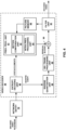
- FIG. 3 is a block diagram illustrating an example video encoder 20 that may implement the techniques described in this disclosure.
- Video encoder 20 may perform intra- and inter-coding of video blocks within video slices.
- Intra-coding relies on spatial prediction to reduce or remove spatial redundancy in video within a given video frame or picture.
- Inter-coding relies on temporal prediction to reduce or remove temporal redundancy in video within adjacent frames or pictures of a video sequence.
- Intra-mode may refer to any of several spatial based compression modes.
- Inter-modes such as uni-directional prediction (P mode) or bi-prediction (B mode), may refer to any of several temporal-based compression modes.
- video encoder 20 includes a partitioning unit 35, prediction processing unit 41, filter unit 63, picture memory 64, summer 50, transform processing unit 52, quantization unit 54, and entropy encoding unit 56.
- Prediction processing unit 41 includes motion estimation unit 42, motion compensation unit 44, and intra prediction processing unit 46.
- video encoder 20 also includes inverse quantization unit 58, inverse transform processing unit 60, and summer 62.
- Filter unit 63 is intended to represent one or more loop filters such as a deblocking filter, an adaptive loop filter (ALF), and a sample adaptive offset (SAO) filter. Although filter unit 63 is shown in FIG.
- filter unit 63 may be implemented as a post loop filter.
- FIG. 3 also shows post-processing device 57 which may perform additional processing on encoded video data generated by video encoder 20.
- the techniques of this disclosure may in some instances be implemented by video encoder 20. In other instances, however, the techniques of this disclosure may be implemented by post-processing device 57.
- the techniques described with respect to packetizer 21 of FIG. 1 may, in some instances, be performed by a packetizer of post-processing device 57.
- video encoder 20 receives video data, and partitioning unit 35 partitions the data into video blocks. This partitioning may also include partitioning into slices, tiles, or other larger units, as wells as video block partitioning, e.g., according to a quadtree structure of LCUs and CUs.
- Video encoder 20 generally illustrates the components that encode video blocks within a video slice to be encoded. The slice may be divided into multiple video blocks (and possibly into sets of video blocks referred to as tiles).
- Prediction processing unit 41 may select one of a plurality of possible coding modes, such as one of a plurality of intra coding modes or one of a plurality of inter coding modes, for the current video block based on error results (e.g., coding rate and the level of distortion). Prediction processing unit 41 may provide the resulting intra- or inter-coded block to summer 50 to generate residual block data and to summer 62 to reconstruct the encoded block for use as a reference picture.
- error results e.g., coding rate and the level of distortion
- Intra prediction processing unit 46 within prediction processing unit 41 may perform intra-predictive coding of the current video block relative to one or more neighboring blocks in the same frame or slice as the current block to be coded to provide spatial compression.
- Motion estimation unit 42 and motion compensation unit 44 within prediction processing unit 41 perform inter-predictive coding of the current video block relative to one or more predictive blocks in one or more reference pictures to provide temporal compression.
- Motion estimation unit 42 may be configured to determine the inter-prediction mode for a video slice according to a predetermined pattern for a video sequence.
- the predetermined pattern may designate video slices in the sequence as P slices, B slices or GPB slices.
- Motion estimation unit 42 and motion compensation unit 44 may be highly integrated, but are illustrated separately for conceptual purposes.
- Motion estimation, performed by motion estimation unit 42 is the process of generating motion vectors, which estimate motion for video blocks.
- a motion vector for example, may indicate the displacement of a PU of a video block within a current video frame or picture relative to a predictive block within a reference picture.
- a predictive block is a block that is found to closely match the PU of the video block to be coded in terms of pixel difference, which may be determined by sum of absolute difference (SAD), sum of square difference (SSD), or other difference metrics.
- video encoder 20 may calculate values for sub-integer pixel positions of reference pictures stored in picture memory 64. For example, video encoder 20 may interpolate values of one-quarter pixel positions, one-eighth pixel positions, or other fractional pixel positions of the reference picture. Therefore, motion estimation unit 42 may perform a motion search relative to the full pixel positions and fractional pixel positions and output a motion vector with fractional pixel precision.
- Motion estimation unit 42 calculates a motion vector for a PU of a video block in an inter-coded slice by comparing the position of the PU to the position of a predictive block of a reference picture.
- the reference picture may be selected from a first reference picture list (List 0) or a second reference picture list (List 1), each of which identify one or more reference pictures stored in picture memory 64.
- Motion estimation unit 42 sends the calculated motion vector to entropy encoding unit 56 and motion compensation unit 44.
- Motion compensation performed by motion compensation unit 44, may involve fetching or generating the predictive block based on the motion vector determined by motion estimation, possibly performing interpolations to sub-pixel precision.
- motion compensation unit 44 may locate the predictive block to which the motion vector points in one of the reference picture lists.
- Video encoder 20 forms a residual video block by subtracting pixel values of the predictive block from the pixel values of the current video block being coded, forming pixel difference values.
- the pixel difference values form residual data for the block, and may include both luma and chroma difference components.
- Summer 50 represents the component or components that perform this subtraction operation.
- Motion compensation unit 44 may also generate syntax elements associated with the video blocks and the video slice for use by video decoder 30 in decoding the video blocks of the video slice.
- Intra prediction processing unit 46 may intra-predict a current block, as an alternative to the inter-prediction performed by motion estimation unit 42 and motion compensation unit 44, as described above. In particular, intra prediction processing unit 46 may determine an intra-prediction mode to use to encode a current block. In some examples, intra prediction processing unit 46 may encode a current block using various intra-prediction modes, e.g., during separate encoding passes, and intra prediction processing unit 46 (or mode select unit 40, in some examples) may select an appropriate intra-prediction mode to use from the tested modes.
- intra prediction processing unit 46 may calculate rate-distortion values using a rate-distortion analysis for the various tested intra-prediction modes, and select the intra-prediction mode having the best rate-distortion characteristics among the tested modes.
- Rate-distortion analysis generally determines an amount of distortion (or error) between an encoded block and an original, unencoded block that was encoded to produce the encoded block, as well as a bit rate (that is, a number of bits) used to produce the encoded block.
- Intra prediction processing unit 46 may calculate ratios from the distortions and rates for the various encoded blocks to determine which intra-prediction mode exhibits the best rate-distortion value for the block.
- intra prediction processing unit 46 may provide information indicative of the selected intra-prediction mode for the block to entropy encoding unit 56.
- Entropy encoding unit 56 may encode the information indicating the selected intra-prediction mode.
- Video encoder 20 may include in the transmitted bitstream configuration data, which may include a plurality of intra-prediction mode index tables and a plurality of modified intra-prediction mode index tables (also referred to as codeword mapping tables), definitions of encoding contexts for various blocks, and indications of a most probable intra-prediction mode, an intra-prediction mode index table, and a modified intra-prediction mode index table to use for each of the contexts.
- video encoder 20 forms a residual video block by subtracting the predictive block from the current video block.
- the residual video data in the residual block may be included in one or more TUs and applied to transform processing unit 52.
- Transform processing unit 52 transforms the residual video data into residual transform coefficients using a transform, such as a discrete cosine transform (DCT) or a conceptually similar transform.
- Transform processing unit 52 may convert the residual video data from a pixel domain to a transform domain, such as a frequency domain.
- DCT discrete cosine transform
- Transform processing unit 52 may send the resulting transform coefficients to quantization unit 54.
- Quantization unit 54 quantizes the transform coefficients to further reduce bit rate. The quantization process may reduce the bit depth associated with some or all of the coefficients. The degree of quantization may be modified by adjusting a quantization parameter.
- quantization unit 54 may then perform a scan of the matrix including the quantized transform coefficients. Alternatively, entropy encoding unit 56 may perform the scan.
- entropy encoding unit 56 entropy encodes the quantized transform coefficients.
- entropy encoding unit 56 may perform context adaptive variable length coding (CAVLC), context adaptive binary arithmetic coding (CABAC), syntax-based context-adaptive binary arithmetic coding (SBAC), probability interval partitioning entropy (PIPE) coding or another entropy encoding methodology or technique.
- CAVLC context adaptive variable length coding
- CABAC context adaptive binary arithmetic coding
- SBAC syntax-based context-adaptive binary arithmetic coding
- PIPE probability interval partitioning entropy
- the encoded bitstream may be transmitted to video decoder 30, or archived for later transmission or retrieval by video decoder 30.
- Entropy encoding unit 56 may also entropy encode the motion vectors and the other syntax elements for the current video slice being coded.
- Inverse quantization unit 58 and inverse transform processing unit 60 apply inverse quantization and inverse transformation, respectively, to reconstruct the residual block in the pixel domain for later use as a reference block of a reference picture.
- Motion compensation unit 44 may calculate a reference block by adding the residual block to a predictive block of one of the reference pictures within one of the reference picture lists. Motion compensation unit 44 may also apply one or more interpolation filters to the reconstructed residual block to calculate sub-integer pixel values for use in motion estimation.
- Summer 62 adds the reconstructed residual block to the motion compensated prediction block produced by motion compensation unit 44 to produce a reference block for storage in picture memory 64.
- the reference block may be used by motion estimation unit 42 and motion compensation unit 44 as a reference block to inter-predict a block in a subsequent video frame or picture.
- FIG. 4 is a block diagram illustrating an example network entity 79 and video decoder 30 that may implement the techniques described in this disclosure.
- video decoder 30 includes an entropy decoding unit 80, prediction processing unit 81, inverse quantization unit 86, inverse transformation processing unit 88, summer 90, filter unit 91, and picture memory 92.
- Prediction processing unit 81 includes motion compensation unit 82 and intra prediction processing unit 84.
- Video decoder 30 may, in some examples, perform a decoding pass generally reciprocal to the encoding pass described with respect to video encoder 20 from FIG. 3 .
- video decoder 30 receives an encoded video bitstream that represents video blocks of an encoded video slice and associated syntax elements from video encoder 20.
- Video decoder 30 may receive the encoded video bitstream from a network entity 79.
- Network entity 79 may, for example, be a server, a MANE, a video editor/splicer, or other such device configured to implement one or more of the techniques described above.
- Network entity 79 may or may not include video encoder 20.
- some of the techniques described in this disclosure may be implemented by network entity 79 prior to network entity 79 transmitting the encoded video bitstream to video decoder 30.
- network entity 79 and video decoder 30 may be parts of separate devices, while in other instances, the functionality described with respect to network entity 79 may be performed by the same device that comprises video decoder 30.
- FIG. 1 shows depacketizer 29 as being part of destination device 14, the techniques described above with respect to depacketizer 29 may also be performed by a depacketizer within network entity 79.
- video decoder 30 receives an encoded video bitstream that represents video blocks of an encoded video slice and associated syntax elements from video encoder 20.
- the video blocks may, for example, be routed from video encoder 20 to video decoder 30 via one or more MANEs, such as MANE 27 in FIG. 1 or network entity 79 in FIG. 4 .
- Entropy decoding unit 80 of video decoder 30 entropy decodes the bitstream to generate quantized coefficients, motion vectors, and other syntax elements. Entropy decoding unit 80 forwards the motion vectors and other syntax elements to prediction processing unit 81.
- Video decoder 30 may receive the syntax elements at the video slice level and/or the video block level.
- intra prediction processing unit 84 of prediction processing unit 81 may generate prediction data for a video block of the current video slice based on a signaled intra prediction mode and data from previously decoded blocks of the current frame or picture.
- motion compensation unit 82 of prediction processing unit 81 produces predictive blocks for a video block of the current video slice based on the motion vectors and other syntax elements received from entropy decoding unit 80.
- the predictive blocks may be produced from one of the reference pictures within one of the reference picture lists.
- Video decoder 30 may construct the reference frame lists, List 0 and List 1, using default construction techniques based on reference pictures stored in picture memory 92.
- Motion compensation unit 82 determines prediction information for a video block of the current video slice by parsing the motion vectors and other syntax elements, and uses the prediction information to produce the predictive blocks for the current video block being decoded. For example, motion compensation unit 82 uses some of the received syntax elements to determine a prediction mode (e.g., intra- or inter-prediction) used to code the video blocks of the video slice, an inter-prediction slice type (e.g., B slice, P slice, or GPB slice), construction information for one or more of the reference picture lists for the slice, motion vectors for each inter-encoded video block of the slice, inter-prediction status for each inter-coded video block of the slice, and other information to decode the video blocks in the current video slice.
- a prediction mode e.g., intra- or inter-prediction
- an inter-prediction slice type e.g., B slice, P slice, or GPB slice
- construction information for one or more of the reference picture lists for the slice motion vectors for each inter-encode
- Motion compensation unit 82 may also perform interpolation based on interpolation filters. Motion compensation unit 82 may use interpolation filters as used by video encoder 20 during encoding of the video blocks to calculate interpolated values for sub-integer pixels of reference blocks. In this case, motion compensation unit 82 may determine the interpolation filters used by video encoder 20 from the received syntax elements and use the interpolation filters to produce predictive blocks.
- Inverse quantization unit 86 inverse quantizes, i.e., de-quantizes, the quantized transform coefficients provided in the bitstream and decoded by entropy decoding unit 80.
- the inverse quantization process may include use of a quantization parameter calculated by video encoder 20 for each video block in the video slice to determine a degree of quantization and, likewise, a degree of inverse quantization that should be applied.
- Inverse transform processing unit 88 applies an inverse transform, e.g., an inverse DCT, an inverse integer transform, or a conceptually similar inverse transform process, to the transform coefficients in order to produce residual blocks in the pixel domain.
- video decoder 30 forms a decoded video block by summing the residual blocks from inverse transform processing unit 88 with the corresponding predictive blocks generated by motion compensation unit 82.
- Summer 90 represents the component or components that perform this summation operation.
- loop filters may also be used to smooth pixel transitions, or otherwise improve the video quality.
- Filter unit 91 is intended to represent one or more loop filters such as a deblocking filter, an adaptive loop filter (ALF), and a sample adaptive offset (SAO) filter. Although filter unit 91 is shown in FIG.
- filter unit 91 may be implemented as a post loop filter.
- the decoded video blocks in a given frame or picture are then stored in picture memory 92, which stores reference pictures used for subsequent motion compensation.
- Picture memory 92 also stores decoded video for later presentation on a display device, such as display device 32 of FIG. 1 .
- FIG. 5 is a block diagram illustrating an example set of devices that form part of network 150.
- network 150 includes routing devices 154A, 154B (routing devices 154) and transcoding device 156.
- Routing devices 154 and transcoding device 156 are intended to represent a small number of devices that may form part of network 150.
- Other network devices such as switches, hubs, gateways, firewalls, bridges, and other such devices may also be included within network 150.
- additional network devices may be provided along a network path between server device 152 and client device 158.
- Server device 152 may correspond to source device 12 ( FIG. 1 )
- client device 158 may correspond to destination device 14 ( FIG. 1 ), in some examples.
- Routing devices 154 may, for example, be MANEs configured to rout media data.
- routing devices 154 implement one or more routing protocols to exchange network data through network 150.
- routing devices 154 execute routing protocols to discover routes through network 150.
- routing device 154B may discover a network route from itself to server device 152 via routing device 154A.
- the various devices of FIG. 5 represent examples of devices that may implement the techniques of this disclosure and may be configured to process RTP data in accordance with the techniques of this disclosure.
- FIG. 6 shows an example of a method of processing video data according to the techniques of this disclosure.
- the techniques of FIG. 6 may, for example, be performed by a device such as destination device 14, and more particularly, may be performed by depacketizer 29 of destination device 14.
- Depacketizer 29 receives first aggregation packet according to an RTP protocol (160).
- the first aggregation packet includes a payload header and two or more aggregation units.
- Depacketizer 29 may parse the first aggregation unit to determine a value for a first parameter (162).
- the first parameter consists of the DONL parameter discussed above and specifies a decoding order number.
- Depacketizer 29 may parse the second aggregation unit to determine a value for a second parameter (164).
- the second aggregation unit follows the first aggregation unit, and the second parameter corresponds to the DOND parameter discussed above. Based on the first parameter and the second parameter, depacketizer 29 determines a de
- FIG. 7 shows an example of a method of processing video data according to the techniques of this disclosure.
- the techniques of FIG. 7 may, for example, be performed by a device such as source device 12, and more particularly, may be performed by packetizer 21 of source device 12.
- Packetizer 21 receives two or more NAL units and packetizes the two or more NAL units into a first aggregation packet according to an RTP protocol (170).
- the first aggregation packet includes a payload header and two or more aggregation units.
- Packetizer 21 sets a value for a first parameter of a first aggregation unit based on a decoding order number for the NAL unit included in the first aggregation unit (172).
- the first parameter consists of the 16 least significant bits of the decoding order number for the first NAL unit.
- Packetizer 21 sets a value for a second parameter of a second aggregation unit (174).
- the second aggregation unit follows the first aggregation unit, and the second parameter corresponds to the DOND parameter discussed above.
- the second parameter identifies a difference between the first parameter and the decoding order number.
- FIG. 8 shows an example of a method of processing video data, which does not form part of the claimed invention where aggregation packets are not fragmented.
- the techniques of FIG. 8 may, for example, be performed by a device such as destination device 14, and more particularly, may be performed by depacketizer 29 of destination device 14.
- Depacketizer 29 receives a first fragmentation unit that includes a subset of a fragmented NAL unit (180).
- Depacketizer 29 parses a start bit of the fragmentation unit to determine if the first fragmentation unit includes a start of the fragmented NAL unit (182).
- the start bit may, for example, be an S bit as described above.
- depacketizer 29 parses a second parameter to determine a decoding order for the fragmented NAL unit.
- the first parameter may, for example, be a sprop-depack-buf-nalus parameter as described above, and the first value may be zero.
- the second parameter may, for example, be a DONL parameter as described above.
- Destination device 14 may decode the fragmented NAL unit based on the determined decoding order (186).
- FIG. 9 shows an example of a method of processing video data, but do not form part of the claimed invention where aggregation packets are not fragmented.
- the techniques of FIG. 9 may, for example, be performed by a device such as source device 12, and more particularly, may be performed by packetizer 21 of source device 12.
- Packetizer 21 generates first fragmentation unit comprising a subset of a fragmented NAL unit (190).
- the first fragmentation unit for example, includes a start of the fragmented NAL unit.
- Packetizer 21 sets the start bit of the fragmentation unit to indicate the first fragmentation unit includes the start of the fragmented NAL unit (192).
- the start bit may, for example, be an S bit as described above.
- Packetizer 21 In response to the first fragmentation unit including the start of the fragmented NAL unit and one or both of a transmission mode for the first fragmentation unit being a multi-session transmission mode and a first parameter being greater than a first value.
- Packetizer 21 sets a second parameter to indicate a decoding order for the fragmented NAL unit.
- the first parameter may, for example, be an sprop-depack-buf-nalus parameter as described above, and the first value may be zero.
- the second parameter may, for example, be a DONL parameter as described above. Packetizer 21 may transmit the fragmented NAL unit (196).
- the first parameter may, for example, specify a maximum number of NAL units that precede the first NAL unit in a de-packetization buffer in reception order and follow the first NAL unit in a decoding order
- the second parameter may specify a value of a number of least significant bits of the decoding order number
- FIG. 10 shows an example of a method that can be used for processing video data where the claimed condition of the transmission mode being a multi session transmission mode or where the maximum number of NAL units that precede a NAL unit in a depacketization buffer in reception order and follow the NAL unit in decoding order is greater than zero is not met.
- the techniques of FIG. 8 may, for example, be performed by a device such as destination device 14, and more particularly, may be performed by depacketizer 29 of destination device 14.
- Depacketizer 29 receives a first RTP packet comprising a first NA unit (200).
- depacketizer 29 determines a decoding order number for the first NAL unit based on a transmission order of the first NAL unit (202).
- the first parameter may, for example, be a sprop-depack-buf-nalus parameter as described above, and the value may be equal to zero.
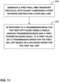
- FIG. 11 shows an example of a method that can be used for processing video data where the claimed condition of the transmission mode being a multi session transmission mode or where the maximum number of NAL units that precede a NAL unit in a depacketization buffer in reception order and follow the NAL unit in decoding order is greater than zero is not met.
- the techniques of FIG. 9 may, for example, be performed by a device such as source device 12, and more particularly, may be performed by packetizer 21 of source device 12. Packetizer 21 generating a RTP packet comprising a first NAL unit (210).
- the first parameter may, for example, be a sprop-depack-buf-nalus parameter as described above.
- Computer-readable media may include computer-readable storage media, which corresponds to a tangible medium such as data storage media, or communication media including any medium that facilitates transfer of a computer program from one place to another, e.g., according to a communication protocol.
- Computer-readable media generally may correspond to (1) tangible computer-readable storage media which is non-transitory or (2) a communication medium such as a signal or carrier wave.
- Data storage media may be any available media that can be accessed by one or more computers or one or more processors to retrieve instructions, code and/or data structures for implementation of the techniques described in this disclosure.
- a computer program product may include a computer-readable medium.
- such computer-readable storage media can comprise RAM, ROM, EEPROM, CD-ROM or other optical disk storage, magnetic disk storage, or other magnetic storage devices, flash memory, or any other medium that can be used to store desired program code in the form of instructions or data structures and that can be accessed by a computer.
- any connection is properly termed a computer-readable medium.
- a computer-readable medium For example, if instructions are transmitted from a website, server, or other remote source using a coaxial cable, fiber optic cable, twisted pair, digital subscriber line (DSL), or wireless technologies such as infrared, radio, and microwave, then the coaxial cable, fiber optic cable, twisted pair, DSL, or wireless technologies such as infrared, radio, and microwave are included in the definition of medium.
- DSL digital subscriber line
- Disk and disc includes compact disc (CD), laser disc, optical disc, digital versatile disc (DVD), floppy disk and Blu-ray disc, where disks usually reproduce data magnetically, while discs reproduce data optically with lasers. Combinations of the above should also be included within the scope of computer-readable media.
- processors such as one or more digital signal processors (DSPs), general purpose microprocessors, application specific integrated circuits (ASICs), field programmable logic arrays (FPGAs), or other equivalent integrated or discrete logic circuitry.
- DSPs digital signal processors
- ASICs application specific integrated circuits
- FPGAs field programmable logic arrays
- processors may refer to any of the foregoing structure or any other structure suitable for implementation of the techniques described herein.
- the functionality described herein may be provided within dedicated hardware and/or software modules configured for encoding and decoding, or incorporated in a combined codec. Also, the techniques could be fully implemented in one or more circuits or logic elements.
- the techniques of this disclosure may be implemented in a wide variety of devices or apparatuses, including a wireless handset, an integrated circuit (IC) or a set of ICs (e.g., a chip set).
- IC integrated circuit
- a set of ICs e.g., a chip set.
- Various components, modules, or units are described in this disclosure to emphasize functional aspects of devices configured to perform the disclosed techniques, but do not necessarily require realization by different hardware units. Rather, as described above, various units may be combined in a codec hardware unit or provided by a collection of interoperative hardware units, including one or more processors as described above, in conjunction with suitable software and/or firmware.
Claims (7)
- Procédé de traitement de données vidéo, le procédé comprenant :la réception d'un premier paquet d'agrégation conformément à un protocole de transfert en temps réel (RTP), dans lequel le premier paquet d'agrégation comprend un en-tête de charge utile suivi de données de charge utile comprenant une première unité d'agrégation, laquelle est la première unité d'agrégation du premier paquet d'agrégation, comportant une première unité de couche d'abstraction réseau (NAL), les données de charge utile comprenant en outre une deuxième unité d'agrégation, laquelle suit la première unité d'agrégation dans le premier paquet d'agrégation, comportant une deuxième unité NAL, dans lequel si un mode de transmission est égal à une transmission multisession, MST, ou si le nombre maximum d'unités NAL qui précèdent une unité NAL dans un tampon de dépaquétisation dans l'ordre de réception et suivent l'unité NAL dans l'ordre de décodage est supérieur à 0, la première unité d'agrégation comporte en outre un premier élément de syntaxe et la deuxième unité d'agrégation comporte en outre un deuxième élément de syntaxe ;dans lequel le premier élément de syntaxe est constitué des 16 bits de poids faible du numéro d'ordre de décodage de la première unité NAL ;dans lequel le deuxième élément de syntaxe plus 1 spécifie une différence entre le numéro d'ordre de décodage de la première unité NAL et le numéro d'ordre de décodage de la deuxième unité NAL ; etla détermination d'un ordre de décodage pour la deuxième unité NAL incluse dans la deuxième unité d'agrégation, dans lequel l'ordre de décodage de la deuxième unité NAL incluse dans la deuxième unité d'agrégation est dérivé pour être égal au premier élément de syntaxe plus le deuxième élément de syntaxe plus 1 modulo 65536.
- Procédé selon la revendication 1, dans lequel le premier paquet d'agrégation comprend en outre une troisième unité d'agrégation, la troisième unité d'agrégation comportant une troisième unité NAL et un troisième élément de syntaxe, dans lequel la troisième unité d'agrégation suit la deuxième unité d'agrégation dans le premier paquet d'agrégation, et dans lequel le troisième élément de syntaxe plus 1 spécifie une différence entre le numéro d'ordre de décodage de la deuxième unité NAL et un numéro d'ordre de décodage de la troisième unité NAL ; le procédé comprenant en outre :
la détermination d'un ordre de décodage pour la troisième unité NAL incluse dans la troisième unité d'agrégation, dans lequel l'ordre de décodage de la troisième unité NAL incluse dans la troisième unité d'agrégation est dérivé comme étant égal au numéro d'ordre de décodage déterminé de la deuxième unité NAL plus le troisième élément de syntaxe plus 1 modulo 65536. - Procédé de traitement de données vidéo, le procédé comprenant :la paquétisation de deux unités de couche d'abstraction réseau (NAL) ou plus en un premier paquet d'agrégation conformément à un protocole RTP, dans lequel le premier paquet d'agrégation comprend un en-tête de charge utile suivi de données de charge utile comprenant une première unité d'agrégation, laquelle est la première unité d'agrégation du paquet d'agrégation, comportant une première unité NAL, les données de charge utile comprenant en outre une deuxième unité d'agrégation, laquelle suit la première unité d'agrégation dans le premier paquet d'agrégation, comportant une deuxième unité NAL, dans lequel si un mode de transmission est égal à une transmission multisession, MST, ou si le nombre maximum d'unités NAL qui précèdent une unité NAL dans un tampon de dépaquétisation dans l'ordre de réception et suivent l'unité NAL dans l'ordre de décodage est supérieur à 0, la première unité d'agrégation comporte en outre un premier élément de syntaxe et la deuxième unité d'agrégation comprend en outre un deuxième élément de syntaxe ;le paramétrage d'une valeur pour le premier élément de syntaxe de la première unité d'agrégation, le premier élément de syntaxe étant constitué des 16 bits de poids faible du numéro d'ordre de décodage de la première unité NAL ; etle paramétrage d'une valeur pour le deuxième élément de syntaxe de la deuxième unité d'agrégation, et dans lequel le deuxième élément de syntaxe plus 1 spécifie une différence entre le numéro d'ordre de décodage de la première unité NAL incluse dans la première unité d'agrégation et un numéro d'ordre de décodage de la deuxième unité NAL, dans lequel la valeur du deuxième élément de syntaxe est dérivée comme étant égale à un ordre de décodage de la deuxième unité d'agrégation moins le premier élément de syntaxe moins 1 modulo 65536.
- Dispositif de traitement de données vidéo, le dispositif comprenant :une mémoire ;un récepteur configuré pour des paquets RTP de protocole de transport en temps réel (RTP) ;un ou plusieurs processeurs configurés pour :recevoir un premier paquet d'agrégation conformément à un protocole de transfert en temps réel (RTP), dans lequel le premier paquet d'agrégation comprend un en-tête de charge utile suivi de données de charge utile comprenant une première unité d'agrégation, laquelle est la première unité d'agrégation du premier paquet d'agrégation, comportant une première unité de couche d'abstraction réseau (NAL), les données de charge utile comprenant en outre une deuxième unité d'agrégation, laquelle suit la première unité d'agrégation dans le premier paquet d'agrégation, comportant une deuxième unité NAL, dans lequel si un mode de transmission est égal à une transmission multisession, MST, ou si le nombre maximum d'unités NAL qui précèdent une unité NAL dans un tampon de dépaquétisation dans l'ordre de réception et suivent l'unité NAL dans l'ordre de décodage est supérieur à 0, la première unité d'agrégation comporte en outre un premier élément de syntaxe et la deuxième unité d'agrégation comporte en outre un deuxième élément de syntaxe ;dans lequel le premier élément de syntaxe est constitué des 16 bits de poids faible du numéro d'ordre de décodage de la première unité NAL ;dans lequel le deuxième élément de syntaxe plus 1 spécifie une différence entre le numéro d'ordre de décodage de la première unité NAL et le numéro d'ordre de décodage de la deuxième unité NAL ; etdéterminer un ordre de décodage pour la deuxième unité NAL incluse dans la deuxième unité d'agrégation, dans lequel l'ordre de décodage de la deuxième unité NAL incluse dans la deuxième unité d'agrégation est dérivé pour être égal au premier élément de syntaxe plus le deuxième élément de syntaxe plus 1 modulo 65536.
- Dispositif selon la revendication 4, dans lequel le premier paquet d'agrégation comprend en outre une troisième unité d'agrégation, la troisième unité d'agrégation comprenant une troisième unité NAL et un troisième élément de syntaxe, dans lequel la troisième unité d'agrégation suit la deuxième unité d'agrégation dans le premier paquet d'agrégation, et dans lequel le troisième élément de syntaxe plus 1 spécifie une différence entre le numéro d'ordre de décodage de la deuxième unité NAL et un numéro d'ordre de décodage de la troisième unité NAL; et dans lequel les un ou plusieurs processeurs sont configurés pour
déterminer un ordre de décodage pour la troisième unité NAL incluse dans la troisième unité d'agrégation, dans lequel l'ordre de décodage de la troisième unité NAL incluse dans la troisième unité d'agrégation est dérivé comme étant égal au numéro d'ordre de décodage déterminé de la deuxième unité NAL plus le troisième élément de syntaxe plus 1 modulo 65536. - Dispositif selon la revendication 4, dans lequel le dispositif comprend au moins :un circuit intégré ;un microprocesseur ; etun dispositif de communication sans fil comprenant un codeur vidéo.
- Support de stockage lisible par ordinateur stockant des instructions qui, à leur exécution par un ou plusieurs processeurs, amènent les un ou plusieurs processeurs à réaliser le procédé selon l'une quelconque des revendications 1 à 3.
Applications Claiming Priority (3)
| Application Number | Priority Date | Filing Date | Title |
|---|---|---|---|
| US201361806705P | 2013-03-29 | 2013-03-29 | |
| US14/228,164 US9641834B2 (en) | 2013-03-29 | 2014-03-27 | RTP payload format designs |
| PCT/US2014/032231 WO2014160970A1 (fr) | 2013-03-29 | 2014-03-28 | Concepts améliorés pour les formats de charge utile rtp |
Related Child Applications (1)
| Application Number | Title | Priority Date | Filing Date |
|---|---|---|---|
| EP22205922.2 Division-Into | 2022-11-07 |
Publications (3)
| Publication Number | Publication Date |
|---|---|
| EP2979456A1 EP2979456A1 (fr) | 2016-02-03 |
| EP2979456C0 EP2979456C0 (fr) | 2023-07-12 |
| EP2979456B1 true EP2979456B1 (fr) | 2023-07-12 |
Family
ID=51620833
Family Applications (3)
| Application Number | Title | Priority Date | Filing Date |
|---|---|---|---|
| EP14724585.6A Active EP2979456B1 (fr) | 2013-03-29 | 2014-03-28 | Concepts améliorés pour les formats de charge utile rtp |
| EP14722918.1A Active EP2979455B1 (fr) | 2013-03-29 | 2014-03-28 | Modèles améliorés de format de charge utile rtp |
| EP14720445.7A Withdrawn EP2979454A1 (fr) | 2013-03-29 | 2014-03-28 | Concepts améliorés pour les formats de charge utile rtp |
Family Applications After (2)
| Application Number | Title | Priority Date | Filing Date |
|---|---|---|---|
| EP14722918.1A Active EP2979455B1 (fr) | 2013-03-29 | 2014-03-28 | Modèles améliorés de format de charge utile rtp |
| EP14720445.7A Withdrawn EP2979454A1 (fr) | 2013-03-29 | 2014-03-28 | Concepts améliorés pour les formats de charge utile rtp |
Country Status (9)
| Country | Link |
|---|---|
| US (3) | US9667959B2 (fr) |
| EP (3) | EP2979456B1 (fr) |
| JP (4) | JP6333949B2 (fr) |
| KR (3) | KR101814266B1 (fr) |
| CN (3) | CN105052149B (fr) |
| BR (1) | BR112015025046A2 (fr) |
| ES (1) | ES2656470T3 (fr) |
| HU (1) | HUE034945T2 (fr) |
| WO (3) | WO2014160971A1 (fr) |
Families Citing this family (17)
| Publication number | Priority date | Publication date | Assignee | Title |
|---|---|---|---|---|
| US9667959B2 (en) | 2013-03-29 | 2017-05-30 | Qualcomm Incorporated | RTP payload format designs |
| US9350781B2 (en) * | 2013-05-31 | 2016-05-24 | Qualcomm Incorporated | Single network abstraction layer unit packets with decoding order number for video coding |
| JP2015136060A (ja) * | 2014-01-17 | 2015-07-27 | ソニー株式会社 | 通信装置、通信データ生成方法、および通信データ処理方法 |
| US9775170B2 (en) | 2014-12-04 | 2017-09-26 | Intel Corporation | Apparatus, system and method of allocation using a frame |
| US9502130B2 (en) * | 2015-03-06 | 2016-11-22 | Kabushiki Kaisha Toshiba | Semiconductor memory device |
| CN106303537B (zh) * | 2016-08-30 | 2019-05-10 | 北京容联易通信息技术有限公司 | 一种openh264多码流传输方法 |
| CN106534137B (zh) * | 2016-11-18 | 2020-01-14 | 浙江宇视科技有限公司 | 媒体流传输方法及装置 |
| US11792686B2 (en) * | 2019-06-19 | 2023-10-17 | Qualcomm Incorporated | High bandwidth low latency cellular traffic awareness |
| JP2023508665A (ja) | 2019-12-26 | 2023-03-03 | バイトダンス インコーポレイテッド | ビデオコーディングにおける復号パラメータセット |
| JP7405990B2 (ja) | 2019-12-26 | 2023-12-26 | バイトダンス インコーポレイテッド | コーディングされたピクチャ内における復号順を実装する技術 |
| US11792432B2 (en) * | 2020-02-24 | 2023-10-17 | Tencent America LLC | Techniques for signaling and identifying access unit boundaries |
| CN113453006B (zh) * | 2020-03-25 | 2024-04-16 | 腾讯美国有限责任公司 | 一种图片封装方法、设备以及存储介质 |
| US11539820B2 (en) * | 2020-03-25 | 2022-12-27 | Tencent America LLC | Signaling and identifying picture boundary in video payload format over IP network |
| CN113645192A (zh) * | 2021-07-16 | 2021-11-12 | 青岛小鸟看看科技有限公司 | Rtp数据包处理方法及装置 |
| WO2023022578A1 (fr) * | 2021-08-20 | 2023-02-23 | 엘지전자 주식회사 | Procédé et dispositif de traitement de signal d'image |
| WO2023073283A1 (fr) * | 2021-10-28 | 2023-05-04 | Nokia Technologies Oy | Procédé, appareil et produit-programme informatique de codage et de décodage vidéo |
| WO2024075100A1 (fr) * | 2022-11-25 | 2024-04-11 | Lenovo (Singapore) Pte. Ltd. | Techniques pour applications sensibles à un ensemble pdu et signalisation associée |
Family Cites Families (60)
| Publication number | Priority date | Publication date | Assignee | Title |
|---|---|---|---|---|
| IT1159034B (it) | 1983-06-10 | 1987-02-25 | Cselt Centro Studi Lab Telecom | Sintetizzatore vocale |
| JP3849210B2 (ja) | 1996-09-24 | 2006-11-22 | ヤマハ株式会社 | 音声符号化復号方式 |
| US6263312B1 (en) | 1997-10-03 | 2001-07-17 | Alaris, Inc. | Audio compression and decompression employing subband decomposition of residual signal and distortion reduction |
| AUPP272698A0 (en) | 1998-03-31 | 1998-04-23 | Lake Dsp Pty Limited | Soundfield playback from a single speaker system |
| JP2002094989A (ja) | 2000-09-14 | 2002-03-29 | Pioneer Electronic Corp | ビデオ信号符号化装置及びビデオ信号符号化方法 |
| GB2379147B (en) | 2001-04-18 | 2003-10-22 | Univ York | Sound processing |
| FR2844894B1 (fr) | 2002-09-23 | 2004-12-17 | Remy Henri Denis Bruno | Procede et systeme de traitement d'une representation d'un champ acoustique |
| JP5068947B2 (ja) | 2003-02-18 | 2012-11-07 | ノキア コーポレイション | ピクチャの符号化方法 |
| CN100568964C (zh) * | 2003-02-18 | 2009-12-09 | 诺基亚有限公司 | 图像解码方法 |
| US20050008240A1 (en) * | 2003-05-02 | 2005-01-13 | Ashish Banerji | Stitching of video for continuous presence multipoint video conferencing |
| US7483532B2 (en) | 2003-07-03 | 2009-01-27 | Microsoft Corporation | RTP payload format |
| US20050201471A1 (en) * | 2004-02-13 | 2005-09-15 | Nokia Corporation | Picture decoding method |
| US7542435B2 (en) | 2004-05-12 | 2009-06-02 | Nokia Corporation | Buffer level signaling for rate adaptation in multimedia streaming |
| US7675872B2 (en) * | 2004-11-30 | 2010-03-09 | Broadcom Corporation | System, method, and apparatus for displaying pictures |
| DE102005001286A1 (de) | 2005-01-11 | 2006-07-20 | Siemens Ag | Verfahren und Vorrichtung zur Übertragung von skalierbaren Daten |
| JP3987541B2 (ja) * | 2005-03-24 | 2007-10-10 | 株式会社東芝 | パケットストリーム受信装置 |
| US7593032B2 (en) * | 2005-07-20 | 2009-09-22 | Vidyo, Inc. | System and method for a conference server architecture for low delay and distributed conferencing applications |
| CN101371312B (zh) | 2005-12-08 | 2015-12-02 | 维德约股份有限公司 | 用于视频通信系统中的差错弹性和随机接入的系统和方法 |
| US8767818B2 (en) * | 2006-01-11 | 2014-07-01 | Nokia Corporation | Backward-compatible aggregation of pictures in scalable video coding |
| US8712061B2 (en) | 2006-05-17 | 2014-04-29 | Creative Technology Ltd | Phase-amplitude 3-D stereo encoder and decoder |
| US20080040498A1 (en) | 2006-08-10 | 2008-02-14 | Nokia Corporation | System and method of XML based content fragmentation for rich media streaming |
| US8060651B2 (en) | 2006-08-17 | 2011-11-15 | Sharp Laboratories Of America, Inc. | Systems and methods for adaptively packetizing data partitions for transport over a network |
| JP2010503266A (ja) * | 2006-08-29 | 2010-01-28 | トムソン ライセンシング | 喪失パケットを有するコンテナファイルに含まれるサンプルを修復するための方法及び装置 |
| WO2008039857A2 (fr) | 2006-09-26 | 2008-04-03 | Dilithium Networks Pty Ltd. | Procede et appareil de conversion de train de bits video comprime a retard algorithmique reduit |
| KR100776680B1 (ko) * | 2006-11-09 | 2007-11-19 | 한국전자통신연구원 | Svc 비디오 압축 비트스트림에 대한 패킷타입 분류방법과 이를 이용한 rtp 패킷화 장치 및 그 방법 |
| US20080205529A1 (en) | 2007-01-12 | 2008-08-28 | Nokia Corporation | Use of fine granular scalability with hierarchical modulation |
| KR101072341B1 (ko) * | 2007-01-18 | 2011-10-11 | 노키아 코포레이션 | Rtp 페이로드 포맷에서의 sei 메시지들의 전송 |
| RU2510908C2 (ru) | 2007-02-23 | 2014-04-10 | Нокиа Корпорейшн | Описание характеристик агрегированных блоков медиаданных с обратной совместимостью |
| US8352625B2 (en) * | 2007-09-24 | 2013-01-08 | Nokia Corporation | Coded application data unit order recovery in layered multicast |
| EP2086237B1 (fr) | 2008-02-04 | 2012-06-27 | Alcatel Lucent | Procédé et dispositif pour enregistrer et multidiffuser des paquets multimédia à partir de flux multimédia appartenant à des sessions apparentées |
| US9357233B2 (en) | 2008-02-26 | 2016-05-31 | Qualcomm Incorporated | Video decoder error handling |
| WO2009114557A1 (fr) * | 2008-03-10 | 2009-09-17 | Vidyo, Inc. | Système et procédé pour récupérer l'ordre de décodage de séquences multimédia en couches en communication à base de paquets |
| US20100049865A1 (en) | 2008-04-16 | 2010-02-25 | Nokia Corporation | Decoding Order Recovery in Session Multiplexing |
| WO2010002420A1 (fr) * | 2008-07-01 | 2010-01-07 | Thomson Licensing | Multiplexeur guidé par couche d'abstraction réseau (nal) |
| US8582644B2 (en) | 2008-07-26 | 2013-11-12 | Thomson Licensing | Real-time transport protocol (RTP) packetization method for fast channel change applications using scalable video coding (SVC) |
| GB0817950D0 (en) | 2008-10-01 | 2008-11-05 | Univ Southampton | Apparatus and method for sound reproduction |
| JP5697301B2 (ja) | 2008-10-01 | 2015-04-08 | 株式会社Nttドコモ | 動画像符号化装置、動画像復号装置、動画像符号化方法、動画像復号方法、動画像符号化プログラム、動画像復号プログラム、及び動画像符号化・復号システム |
| US8207890B2 (en) | 2008-10-08 | 2012-06-26 | Qualcomm Atheros, Inc. | Providing ephemeris data and clock corrections to a satellite navigation system receiver |
| KR100970388B1 (ko) | 2008-10-31 | 2010-07-15 | 한국전자통신연구원 | 네트워크 흐름기반 스케일러블 비디오 코딩 적응 장치 및 그 방법 |
| FR2938688A1 (fr) | 2008-11-18 | 2010-05-21 | France Telecom | Codage avec mise en forme du bruit dans un codeur hierarchique |
| KR20100071688A (ko) | 2008-12-19 | 2010-06-29 | 한국전자통신연구원 | 스케일러블 비디오 코딩 기반의 포괄적 비디오 접근을 위한스트리밍 서비스 장치 및 방법 |
| EP2205007B1 (fr) | 2008-12-30 | 2019-01-09 | Dolby International AB | Procédé et appareil pour le codage tridimensionnel de champ acoustique et la reconstruction optimale |
| GB2467534B (en) | 2009-02-04 | 2014-12-24 | Richard Furse | Sound system |
| KR101644215B1 (ko) * | 2010-01-28 | 2016-08-09 | 톰슨 라이센싱 | 신뢰성 있는 데이터 통신을 위한 네트워크 추상화 계층을 파싱하는 방법 및 장치 |
| US20120300663A1 (en) * | 2010-01-28 | 2012-11-29 | Thomson Licensing | Method and apparatus for retransmission decision making |
| US20110280314A1 (en) | 2010-05-12 | 2011-11-17 | Texas Instruments Incorporated | Slice encoding and decoding processors, circuits, devices, systems and processes |
| EP2450880A1 (fr) | 2010-11-05 | 2012-05-09 | Thomson Licensing | Structure de données pour données audio d'ambiophonie d'ordre supérieur |
| EP2469741A1 (fr) | 2010-12-21 | 2012-06-27 | Thomson Licensing | Procédé et appareil pour coder et décoder des trames successives d'une représentation d'ambiophonie d'un champ sonore bi et tridimensionnel |
| EP2664075A4 (fr) * | 2011-01-14 | 2015-08-19 | Vidyo Inc | En-tête d'unité nal amélioré |
| US9516379B2 (en) * | 2011-03-08 | 2016-12-06 | Qualcomm Incorporated | Buffer management in video codecs |
| CN103546826B (zh) | 2012-07-16 | 2017-07-21 | 上海贝尔股份有限公司 | 视频业务的传输方法和装置 |
| JP5967571B2 (ja) | 2012-07-26 | 2016-08-10 | 本田技研工業株式会社 | 音響信号処理装置、音響信号処理方法、及び音響信号処理プログラム |
| US9667959B2 (en) | 2013-03-29 | 2017-05-30 | Qualcomm Incorporated | RTP payload format designs |
| US9350781B2 (en) | 2013-05-31 | 2016-05-24 | Qualcomm Incorporated | Single network abstraction layer unit packets with decoding order number for video coding |
| GB2519745B (en) | 2013-10-22 | 2018-04-18 | Canon Kk | Method of processing disordered frame portion data units |
| US9502045B2 (en) | 2014-01-30 | 2016-11-22 | Qualcomm Incorporated | Coding independent frames of ambient higher-order ambisonic coefficients |
| US9922656B2 (en) | 2014-01-30 | 2018-03-20 | Qualcomm Incorporated | Transitioning of ambient higher-order ambisonic coefficients |
| US9852737B2 (en) | 2014-05-16 | 2017-12-26 | Qualcomm Incorporated | Coding vectors decomposed from higher-order ambisonics audio signals |
| US10770087B2 (en) | 2014-05-16 | 2020-09-08 | Qualcomm Incorporated | Selecting codebooks for coding vectors decomposed from higher-order ambisonic audio signals |
| US9620137B2 (en) | 2014-05-16 | 2017-04-11 | Qualcomm Incorporated | Determining between scalar and vector quantization in higher order ambisonic coefficients |
-
2014
- 2014-03-27 US US14/228,102 patent/US9667959B2/en active Active
- 2014-03-27 US US14/228,139 patent/US9723305B2/en active Active
- 2014-03-27 US US14/228,164 patent/US9641834B2/en active Active
- 2014-03-28 ES ES14722918.1T patent/ES2656470T3/es active Active
- 2014-03-28 KR KR1020157030518A patent/KR101814266B1/ko active IP Right Grant
- 2014-03-28 WO PCT/US2014/032235 patent/WO2014160971A1/fr active Application Filing
- 2014-03-28 EP EP14724585.6A patent/EP2979456B1/fr active Active
- 2014-03-28 EP EP14722918.1A patent/EP2979455B1/fr active Active
- 2014-03-28 WO PCT/US2014/032231 patent/WO2014160970A1/fr active Application Filing
- 2014-03-28 CN CN201480017375.7A patent/CN105052149B/zh active Active
- 2014-03-28 BR BR112015025046A patent/BR112015025046A2/pt not_active IP Right Cessation
- 2014-03-28 KR KR1020157030516A patent/KR101805282B1/ko active IP Right Grant
- 2014-03-28 CN CN201480017438.9A patent/CN105052150B/zh active Active
- 2014-03-28 KR KR1020157030517A patent/KR101833605B1/ko active IP Right Grant
- 2014-03-28 JP JP2016505610A patent/JP6333949B2/ja active Active
- 2014-03-28 CN CN201480017459.0A patent/CN105052151B/zh active Active
- 2014-03-28 EP EP14720445.7A patent/EP2979454A1/fr not_active Withdrawn
- 2014-03-28 JP JP2016505608A patent/JP6522583B2/ja active Active
- 2014-03-28 WO PCT/US2014/032243 patent/WO2014160974A1/fr active Application Filing
- 2014-03-28 HU HUE14722918A patent/HUE034945T2/en unknown
- 2014-03-28 JP JP2016505609A patent/JP6800747B2/ja active Active
-
2019
- 2019-06-10 JP JP2019107942A patent/JP2019195190A/ja not_active Withdrawn
Non-Patent Citations (1)
| Title |
|---|
| SCHIERL T ET AL: "Wireless broadcasting using the scalable extension of H.264/AVC", 2005 IEEE INTERNATIONAL CONFERENCE ON MULTIMEDIA AND EXPO IEEE PISCATAWAY, NJ, USA,, 6 July 2005 (2005-07-06), pages 884 - 887, XP002484405, ISBN: 978-0-7803-9332-5 * |
Also Published As
Similar Documents
| Publication | Publication Date | Title |
|---|---|---|
| EP2979456B1 (fr) | Concepts améliorés pour les formats de charge utile rtp | |
| JP6125643B2 (ja) | 付加拡張情報メッセージコーディング | |
| EP3005700B1 (fr) | Paquets a une seule unite de couche d'abstraction reseau ayant un numero d'ordre de decodage pour codage video | |
| PH12014502202B1 (en) | Marking reference pictures in video sequences having broken link pictures | |
| US20140010277A1 (en) | Supplemental enhancement information (sei) messages having a fixed-length coded video parameter set (vps) id | |
| WO2013163525A1 (fr) | Codage d'ensemble de paramètres |
Legal Events
| Date | Code | Title | Description |
|---|---|---|---|
| PUAI | Public reference made under article 153(3) epc to a published international application that has entered the european phase |
Free format text: ORIGINAL CODE: 0009012 |
|
| 17P | Request for examination filed |
Effective date: 20150814 |
|
| AK | Designated contracting states |
Kind code of ref document: A1 Designated state(s): AL AT BE BG CH CY CZ DE DK EE ES FI FR GB GR HR HU IE IS IT LI LT LU LV MC MK MT NL NO PL PT RO RS SE SI SK SM TR |
|
| AX | Request for extension of the european patent |
Extension state: BA ME |
|
| DAX | Request for extension of the european patent (deleted) | ||
| 17Q | First examination report despatched |
Effective date: 20160803 |
|
| STAA | Information on the status of an ep patent application or granted ep patent |
Free format text: STATUS: EXAMINATION IS IN PROGRESS |
|
| APBK | Appeal reference recorded |
Free format text: ORIGINAL CODE: EPIDOSNREFNE |
|
| APBN | Date of receipt of notice of appeal recorded |
Free format text: ORIGINAL CODE: EPIDOSNNOA2E |
|
| APBR | Date of receipt of statement of grounds of appeal recorded |
Free format text: ORIGINAL CODE: EPIDOSNNOA3E |
|
| APAF | Appeal reference modified |
Free format text: ORIGINAL CODE: EPIDOSCREFNE |
|
| APBT | Appeal procedure closed |
Free format text: ORIGINAL CODE: EPIDOSNNOA9E |
|
| GRAP | Despatch of communication of intention to grant a patent |
Free format text: ORIGINAL CODE: EPIDOSNIGR1 |
|
| STAA | Information on the status of an ep patent application or granted ep patent |
Free format text: STATUS: GRANT OF PATENT IS INTENDED |
|
| INTG | Intention to grant announced |
Effective date: 20230206 |
|
| GRAS | Grant fee paid |
Free format text: ORIGINAL CODE: EPIDOSNIGR3 |
|
| GRAA | (expected) grant |
Free format text: ORIGINAL CODE: 0009210 |
|
| STAA | Information on the status of an ep patent application or granted ep patent |
Free format text: STATUS: THE PATENT HAS BEEN GRANTED |
|
| AK | Designated contracting states |
Kind code of ref document: B1 Designated state(s): AL AT BE BG CH CY CZ DE DK EE ES FI FR GB GR HR HU IE IS IT LI LT LU LV MC MK MT NL NO PL PT RO RS SE SI SK SM TR |
|
| REG | Reference to a national code |
Ref country code: CH Ref legal event code: EP |
|
| REG | Reference to a national code |
Ref country code: IE Ref legal event code: FG4D |
|
| REG | Reference to a national code |
Ref country code: DE Ref legal event code: R096 Ref document number: 602014087591 Country of ref document: DE |
|
| U01 | Request for unitary effect filed |
Effective date: 20230717 |
|
| U07 | Unitary effect registered |
Designated state(s): AT BE BG DE DK EE FI FR IT LT LU LV MT NL PT SE SI Effective date: 20230724 |
|
| REG | Reference to a national code |
Ref country code: LT Ref legal event code: MG9D |
|
| PG25 | Lapsed in a contracting state [announced via postgrant information from national office to epo] |
Ref country code: GR Free format text: LAPSE BECAUSE OF FAILURE TO SUBMIT A TRANSLATION OF THE DESCRIPTION OR TO PAY THE FEE WITHIN THE PRESCRIBED TIME-LIMIT Effective date: 20231013 |
|
| PG25 | Lapsed in a contracting state [announced via postgrant information from national office to epo] |
Ref country code: ES Free format text: LAPSE BECAUSE OF FAILURE TO SUBMIT A TRANSLATION OF THE DESCRIPTION OR TO PAY THE FEE WITHIN THE PRESCRIBED TIME-LIMIT Effective date: 20230712 |
|
| PG25 | Lapsed in a contracting state [announced via postgrant information from national office to epo] |
Ref country code: IS Free format text: LAPSE BECAUSE OF FAILURE TO SUBMIT A TRANSLATION OF THE DESCRIPTION OR TO PAY THE FEE WITHIN THE PRESCRIBED TIME-LIMIT Effective date: 20231112 |
|
| PG25 | Lapsed in a contracting state [announced via postgrant information from national office to epo] |
Ref country code: RS Free format text: LAPSE BECAUSE OF FAILURE TO SUBMIT A TRANSLATION OF THE DESCRIPTION OR TO PAY THE FEE WITHIN THE PRESCRIBED TIME-LIMIT Effective date: 20230712 Ref country code: NO Free format text: LAPSE BECAUSE OF FAILURE TO SUBMIT A TRANSLATION OF THE DESCRIPTION OR TO PAY THE FEE WITHIN THE PRESCRIBED TIME-LIMIT Effective date: 20231012 Ref country code: IS Free format text: LAPSE BECAUSE OF FAILURE TO SUBMIT A TRANSLATION OF THE DESCRIPTION OR TO PAY THE FEE WITHIN THE PRESCRIBED TIME-LIMIT Effective date: 20231112 Ref country code: HR Free format text: LAPSE BECAUSE OF FAILURE TO SUBMIT A TRANSLATION OF THE DESCRIPTION OR TO PAY THE FEE WITHIN THE PRESCRIBED TIME-LIMIT Effective date: 20230712 Ref country code: GR Free format text: LAPSE BECAUSE OF FAILURE TO SUBMIT A TRANSLATION OF THE DESCRIPTION OR TO PAY THE FEE WITHIN THE PRESCRIBED TIME-LIMIT Effective date: 20231013 Ref country code: ES Free format text: LAPSE BECAUSE OF FAILURE TO SUBMIT A TRANSLATION OF THE DESCRIPTION OR TO PAY THE FEE WITHIN THE PRESCRIBED TIME-LIMIT Effective date: 20230712 |
|
| PG25 | Lapsed in a contracting state [announced via postgrant information from national office to epo] |
Ref country code: PL Free format text: LAPSE BECAUSE OF FAILURE TO SUBMIT A TRANSLATION OF THE DESCRIPTION OR TO PAY THE FEE WITHIN THE PRESCRIBED TIME-LIMIT Effective date: 20230712 |
|
| U20 | Renewal fee paid [unitary effect] |
Year of fee payment: 11 Effective date: 20240212 |
|
| PGFP | Annual fee paid to national office [announced via postgrant information from national office to epo] |
Ref country code: IE Payment date: 20240226 Year of fee payment: 11 |