EP2979245B1 - Image registration - Google Patents
Image registration Download PDFInfo
- Publication number
- EP2979245B1 EP2979245B1 EP14719867.5A EP14719867A EP2979245B1 EP 2979245 B1 EP2979245 B1 EP 2979245B1 EP 14719867 A EP14719867 A EP 14719867A EP 2979245 B1 EP2979245 B1 EP 2979245B1
- Authority
- EP
- European Patent Office
- Prior art keywords
- sub
- range
- intensity values
- pixel intensity
- images
- Prior art date
- Legal status (The legal status is an assumption and is not a legal conclusion. Google has not performed a legal analysis and makes no representation as to the accuracy of the status listed.)
- Active
Links
- 238000000034 method Methods 0.000 claims description 16
- 239000013598 vector Substances 0.000 claims description 14
- 230000011218 segmentation Effects 0.000 claims description 9
- 238000012545 processing Methods 0.000 claims description 4
- 230000003247 decreasing effect Effects 0.000 claims description 2
- 210000001519 tissue Anatomy 0.000 description 33
- 238000003384 imaging method Methods 0.000 description 19
- 230000005855 radiation Effects 0.000 description 11
- 238000013459 approach Methods 0.000 description 9
- 238000002591 computed tomography Methods 0.000 description 6
- 210000004185 liver Anatomy 0.000 description 6
- 238000013507 mapping Methods 0.000 description 5
- 210000000056 organ Anatomy 0.000 description 4
- 238000002595 magnetic resonance imaging Methods 0.000 description 3
- 230000004075 alteration Effects 0.000 description 2
- 210000003484 anatomy Anatomy 0.000 description 2
- 230000008859 change Effects 0.000 description 2
- 230000003993 interaction Effects 0.000 description 2
- 210000005228 liver tissue Anatomy 0.000 description 2
- 238000012986 modification Methods 0.000 description 2
- 230000004048 modification Effects 0.000 description 2
- 238000002600 positron emission tomography Methods 0.000 description 2
- 238000011002 quantification Methods 0.000 description 2
- 238000002603 single-photon emission computed tomography Methods 0.000 description 2
- 210000000988 bone and bone Anatomy 0.000 description 1
- 238000004891 communication Methods 0.000 description 1
- 230000007423 decrease Effects 0.000 description 1
- 230000004069 differentiation Effects 0.000 description 1
- 230000006870 function Effects 0.000 description 1
- 238000012804 iterative process Methods 0.000 description 1
- 230000000116 mitigating effect Effects 0.000 description 1
- 238000005457 optimization Methods 0.000 description 1
- 230000008569 process Effects 0.000 description 1
- 238000002601 radiography Methods 0.000 description 1
- 238000013519 translation Methods 0.000 description 1
Images
Classifications
-
- G—PHYSICS
- G06—COMPUTING; CALCULATING OR COUNTING
- G06T—IMAGE DATA PROCESSING OR GENERATION, IN GENERAL
- G06T5/00—Image enhancement or restoration
- G06T5/90—Dynamic range modification of images or parts thereof
- G06T5/94—Dynamic range modification of images or parts thereof based on local image properties, e.g. for local contrast enhancement
-
- G—PHYSICS
- G06—COMPUTING; CALCULATING OR COUNTING
- G06T—IMAGE DATA PROCESSING OR GENERATION, IN GENERAL
- G06T11/00—2D [Two Dimensional] image generation
- G06T11/003—Reconstruction from projections, e.g. tomography
-
- G—PHYSICS
- G06—COMPUTING; CALCULATING OR COUNTING
- G06T—IMAGE DATA PROCESSING OR GENERATION, IN GENERAL
- G06T7/00—Image analysis
- G06T7/30—Determination of transform parameters for the alignment of images, i.e. image registration
-
- G—PHYSICS
- G06—COMPUTING; CALCULATING OR COUNTING
- G06T—IMAGE DATA PROCESSING OR GENERATION, IN GENERAL
- G06T2207/00—Indexing scheme for image analysis or image enhancement
- G06T2207/10—Image acquisition modality
- G06T2207/10072—Tomographic images
-
- G—PHYSICS
- G06—COMPUTING; CALCULATING OR COUNTING
- G06T—IMAGE DATA PROCESSING OR GENERATION, IN GENERAL
- G06T2207/00—Indexing scheme for image analysis or image enhancement
- G06T2207/20—Special algorithmic details
- G06T2207/20172—Image enhancement details
- G06T2207/20192—Edge enhancement; Edge preservation
-
- G—PHYSICS
- G06—COMPUTING; CALCULATING OR COUNTING
- G06T—IMAGE DATA PROCESSING OR GENERATION, IN GENERAL
- G06T2207/00—Indexing scheme for image analysis or image enhancement
- G06T2207/20—Special algorithmic details
- G06T2207/20172—Image enhancement details
- G06T2207/20208—High dynamic range [HDR] image processing
-
- G—PHYSICS
- G06—COMPUTING; CALCULATING OR COUNTING
- G06T—IMAGE DATA PROCESSING OR GENERATION, IN GENERAL
- G06T2207/00—Indexing scheme for image analysis or image enhancement
- G06T2207/30—Subject of image; Context of image processing
- G06T2207/30004—Biomedical image processing
Definitions
- CT computed tomography
- MRI magnetic resonance imaging
- PET Positron Emission Tomography
- SPECT Single Photon Emission Computed Tomography
- digital radiography and/or other imaging modality.
- a CT scanner generally includes an x-ray tube supported by a rotating frame.
- the rotating frame and the x-ray tube rotate around an examination region, and the x-ray tube emits radiation that traverses the examination region.
- a radiation sensitive detector is located opposite the x-ray tube, across the examination region, and detects radiation that traverses the examination region. The radiation sensitive detector generates a signal indicative of the detected radiation.
- a reconstructor reconstructs the signal, generating volumetric image data.
- An image processor can be used to process the image data and generate an image(s).
- Image registration has been used to determine a correspondence between a tissue of interest in images from different image data sets.
- the application of image registration is broad, covering dynamic contrast imaging, motion compensation, change quantification in follow-up studies, etc.
- Non-rigid image registration is typically implemented as an iterative process in which an image similarity term (e.g., mutual information, sum of squared differences) is maximized, while an additional regularization term keeps the solution in some sense realistic (usually a certain smoothness of the resulting deformation field is wanted).
- an image similarity term e.g., mutual information, sum of squared differences
- High-contrasted image edges are easier to detect than low-contrasted image edges (e.g., the lower boundary of the liver).
- registration schemes tend to align high-contrasted image edges better than low-contrasted ones.
- One mitigation approach includes emphasizing the similarity term at the cost of the regularization term.
- the regularization term is needed to achieve a physiologically plausible result, and a weakened regularization may result in deformation of bone structures.
- Another approach includes using spatially variable regularization to relax the regularization term for low-contrasted image edges. However, this requires prior knowledge such as a detailed segmentation, which may increase time, add complexity, and require user interaction (e.g., manual segmentation).
- Another approach includes using landmarks at low-contrasted image edges. Likewise, this may also require manual user effort to generate and place the landmarks.
- Another approach includes segmenting the tissue in all images and registering the segmented images. This approach is prone to error, e.g., if contrast is low.
- US2004/0013299 provides a method for contrast enhanced registration with complex polynomial interpolation, which allows preserving information contents of the registered images. It maps distinct point to distinct points and preserves the angles in the images.
- EP 2535001 provides a method for registration of diagnostic images taken for different time moments for the same patients allowing for quantification of the differences between both diagnostic images.
- the following relates to improving an accuracy of image registration at least in a presence of low-contrasted tissue interfaces by introducing an intensity map, prior to a registration, and applying it to low-contrasted tissue edges.
- the registration algorithm does not need to be modified, but can be modified.
- an image processing system according to claim 10 is provided.
- the invention may take form in various components and arrangements of components, and in various steps and arrangements of steps.
- the drawings are only for purposes of illustrating the preferred embodiments and are not to be construed as limiting the invention.
- the following describes an approach to improving an accuracy of a registration of images, at least with respect to a low-contrasted tissue interface or boundary in the images.
- the approach includes using an intensity map, which increase a dynamic range of the intensity interval for tissue of interest, prior to determining a deformation field for the registration.
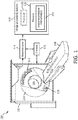
- an imaging system 100 such as a CT scanner is illustrated.
- the imaging system 100 may additionally or alternatively include an MRI scanner, a PET scanner, a SPECT scanner, an X-ray scanner, and/or other imaging modality scanner.
- a generally stationary gantry 102 and a rotating gantry 104 which is rotatably supported by the stationary gantry 102 and rotates around an examination region 106 about a z-axis.
- a subject support 108 such as a couch, supports an object or subject in the examination region 106.
- a radiation source 110 such as an x-ray tube, is rotatably supported by the rotating gantry 104, rotates with the rotating gantry 104, and emits radiation that traverses the examination region 106.
- a radiation sensitive detector array 112 subtends an angular arc opposite the radiation source 110 across the examination region 106.
- the radiation sensitive detector array 112 detects radiation traversing the examination region 106 and generates a signal indicative thereof for each detected photon.
- a reconstructor 114 reconstructs the projection, generating volumetric image data indicative of a scanned portion of a subject or object located in the imaging region 106.
- a computing system or computer serves as an operator console 116.
- the console 116 includes a human readable output device such as a monitor and an input device such as a keyboard, mouse, etc.
- Software resident on the console 116 allows the operator to interact with and/or operate the scanner 100 via a graphical user interface (GUI) or otherwise.
- GUI graphical user interface
- An image processing system 118 includes at least one computer processor 120 (e.g., a microprocessor) that executes at least one computer readable instruction stored in computer readable storage medium, such as physical memory 122 and other non-transitory storage medium.
- the at least one processor 120 may also executes a computer readable instruction(s) carried by a carrier wave, a signal and other transitory medium.
- the computer readable instruction(s) includes an image registration instruction(s) 124.
- excutation of the image registration instruction(s) 124 by the at least one computer processor 120 causes generation and/or selection of an intensity map to apply for image registration. It is to be appreciated that by introducing the intensity map prior to the registration, low-contrasted image edges are strengthened and, therefore, aligned more equally or at least more similar to high-contrasted image edges.
- the intensity map can be determined based on anatomy, imaging protocola, imaging modality , imaging application, and/or other information. This includes generating one or more intensity maps and storing the one or more intensity maps for subsequent use and/or generating an intensity map on demand.
- an intensity map can be generated based on a segmentation of the tissue of interest. The segmentation can be automatic, semi-automatic, or manual, requiring user interaction.
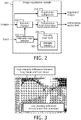
- FIGURE 2 schematically illustrates an example of an image registration module 202 for implementing the image registration instruction(s) 124 ( FIGURE 1 ) that includes pre-generated intensity maps.
- the illustrated image registration module 202 receives, as an input, at least two images to register and outputs at least one of a deformation vector field (also referred to as motion vector field and deformation map) or registered images.
- the input images may be generated by the imaging system 100 and/or other imaging system, and can be obtained from the imaging system and/or a data repository such as a picture archiving and communication system (PACS), a radiology information system (RIS), a hospital information system (HIS), and/or other data repository.
- PACS picture archiving and communication system
- RIS radiology information system
- HIS hospital information system
- An intensity changer 204 changes an intensity of at least a sub-portion of the pixels in the images based on an intensity map. This includes scaling intensities of pixels at edges of tissue of interest with low contrasted tissue boundaries. Such an interface includes, for example, the lower boundary of the liver. This can be seen in FIGURE 3 , which shows a higher-contrasted liver/diaphragm boundary 302 and a lower-contrasted liver boundary 304. Tissue other than liver tissue is also contemplated herein.
- an intensity map bank 206 includes one or more intensity maps (intensity map(s)) 208, which are used by the intensity changer 204 to change pixel intensities.
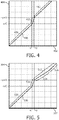
- an intensity map 208 increases the dynamic range (i.e., the number of intensity levels) for a particular range of pixels corresponding to the particular tissue of interest. Examples of intensity maps 208 for liver tissue are graphically shown in FIGURES 4 and 5 .
- an x-axis 402 represents pixels intensity values of the images to be registered
- a y-axis 404 represents modified pixels intensity values
- a curve 406 represents an intensity map that maps the pixels intensity values of the images to be registered to the modified pixels intensity values.
- the pixel intensity values can be in Hounsfield units (HU) or other units.
- all intensities in a first region 408 are mapped 1:1. That is, the modified pixels intensity values and the pixels intensity values of the images to be registered are the same.
- a second region 410 which represents pixel intensity values of the tissue of interest
- a range of -x to +y is mapped to -x-C and +y+D, where x, y, C and D are real numbers and integers, and C may or may not be equal to D.
- the values of C and D represent a scaling of the dynamic range for the tissue of interest.
- the scaling can be linear, as shown, or non-linear, e.g., exponential.
- intensities in a third region 412 are equally shifted based on the scaling applied to the region 410.
- intensities above 50 are all shifted by 200.
- an x-axis value of 100 maps to a y-axis value of 300
- an x-axis value of 250 maps to a y-axis value of 450
- an x-axis value of 750 maps to a y-axis value of 950, etc.
- the intensity value range of the tissue of interest is symmetric about zero (-50 and +50). In another instance, the range is asymmetric about zero (-25 and +50), entirely positive (e.g., 50 to 100), or entirely negative (e.g., -50 to -25).
- the symmetric intensity value range of the tissue of interest (-50 and +50) is mapped to an asymmetric range (-50 and +250) on the y-axis 404. In another instance, the symmetric intensity value range of the x-axis 402 is mapped to a symmetric range about zero on the y-axis 404.
- an x-axis 502 represents pixels intensity values of the images to be registered
- a y-axis 504 represents modified pixels intensity values
- a curve 506 represents an intensity map that maps the pixels values of the images to be registered to the modified pixels values.
- all intensities in a first region 508 are mapped 1:1
- the intensity values in a second region 510 are mapped similar to the mapping of the second region 410 of FIGURE 4 .
- a third region 512 is split into a first sub-region 514 and a second sub-region 516.
- the first sub-region 514 instead of being entirely shifted by the scaling, converges or decreases back to a 1:1 mapping.
- the convergence can be linear, as shown, or non-linear, e.g., exponential.
- the second sub-region 516 is mapped similar to the mapping of the third region 412 of FIGURE 4 , or 1:1. As such, tissue with a pixel value in the second sub-region 516 retains its original pixel value.
- An intensity map 208 can be pre-determined or generated on demand, and the map bank 206 can store intensity maps 208 for a plurality of different tissues and/or combinations of tissue.
- the pixel value range for the particular tissue of interest can be obtained from the input and/or pre-stored in the map bank 206 and/or other storage.
- the tissue maps of FIGURES 4 and 5 include a single range that is scaled. In another instance, a tissue map may scale more than one range.
- an intensity map selector 210 selects a suitable intensity map 208 from the intensity map bank 206 for the intensity shifter 204. As shown, the intensity map selector 210 does this based on an input.
- the input can be data indicative of the tissue of interest or information from which the tissue of interest can be determined such as anatomy, the imaging protocol, the imaging modality, the particular application, and/or other information.
- a deformation vector field (DVF) generator 212 generates a deformation vector field for the intensity shifted images.
- the DVF generator 212 employs a non-rigid (or elastic) image registration algorithm.
- a suitable algorithm includes a representation and parameterization of the mapping between two or more image domains, an objective function combining an image similarity term and a regularization term, and an optimization scheme, e.g., gradient descend, conjugate gradients, etc.
- the representation and parameterization can include, but is not limited to, grid of B-Spline control points, or image voxel wise translation vectors.
- Examples of a similarity term include, but are not limited to, mutual information, sum of squared differences, intensity correlation, etc.
- the regularization term ensures a certain degree of smoothness, by, e.g., penalizing first and/or second derivatives of the mapping field.
- the image similarity term and regularization term can be weighted, e.g., based on image modality, application, etc.
- a registration component 214 registers the input images based on the generated deformation vector field. Again, the image registration module 202 outputs at least one of the deformation vector field or the registered images. The output can be visually displayed, stored, and/or otherwise utilized.
- a rough segmentation of the organ of interest is created.
- the segmentation does not need to be exact.
- a distance transform is applied to the surface of the segmentation. All voxels, M, with a distance smaller than a given threshold (e.g. 20 mm) are collected.
- the histogram of image intensities covered by M is evaluated.
- One peak of the histogram will belong to voxels from the organ (homogeneous intensities on the rim of the organ assumed), and the other peaks will belong to voxels from tissue adjacent to the organ of interest.
- An intensity interval is defined such that one boundary of the interval is given by the smallest peak value, optionally with an added negative offset, and another boundary of the interval is given by the largest peak value, optionally with an added positive offset.
- the intensity interval is used to construct an intensity map.
- the intensity map can be applied as discussed above in connection with FIGURE 2 and/or otherwise. For the former, this includes applying the intensity map to the images, performing an elastic registration, and applying the resulting deformation vector field to the original input images.
- the output of the image registration module 202 can be visually displayed, stored, and/or otherwise utilized.
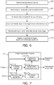
- FIGURE 6 illustrates an example method for improving an accuracy of a registration in connection with tissue of interest with a low contrasted boundary.
- At 602 at least two images to register are obtained.
- tissue of interest with a low contrasted boundary is identified.
- an intensity map is obtained for the tissue of interest, as described herein and/or otherwise.
- pixel intensity values of at least a sub-portion of the pixels are scaled based on the intensity map.
- a deformation vector field is determined for the intensity scaled images.
- the original at least two images are registered based on the deformation vector field.
- the above may be implemented by way of computer readable instructions, encoded or embedded on computer readable storage medium, which, when executed by a computer processor(s), cause the processor(s) to carry out the described acts. Additionally or alternatively, at least one of the computer readable instructions is carried by a signal, carrier wave or other transitory medium.
- FIGURE 7 illustrates a variation of the image registration module 202 of FIGURE 2 .
- image registration module 202 includes an intensity map generator 702.
- the image registration module 202 generates intensity maps on demand rather than selecting pre-determined intensity maps.
- the input can include data indicative of the tissue of interest or information from which the tissue of interest can be determined such as the imaging protocol, the imaging modality, the particular application, and/or other information.
- the input may also include a range of pixel intensity values to scale and/or obtain the range from pre-stored ranges 704.
Landscapes
- Engineering & Computer Science (AREA)
- Physics & Mathematics (AREA)
- General Physics & Mathematics (AREA)
- Theoretical Computer Science (AREA)
- Computer Vision & Pattern Recognition (AREA)
- Apparatus For Radiation Diagnosis (AREA)
- Magnetic Resonance Imaging Apparatus (AREA)
- Image Processing (AREA)
- Image Analysis (AREA)
Description
- The following generally relates to image registration and more particularly to improving an accuracy of image registration, and is described with particular application to computed tomography (CT). However, the following is also amenable to other imaging modalities such as magnetic resonance imaging (MRI), Positron Emission Tomography (PET), Single Photon Emission Computed Tomography (SPECT), digital radiography, and/or other imaging modality.
- A CT scanner generally includes an x-ray tube supported by a rotating frame. The rotating frame and the x-ray tube rotate around an examination region, and the x-ray tube emits radiation that traverses the examination region. A radiation sensitive detector is located opposite the x-ray tube, across the examination region, and detects radiation that traverses the examination region. The radiation sensitive detector generates a signal indicative of the detected radiation. A reconstructor reconstructs the signal, generating volumetric image data. An image processor can be used to process the image data and generate an image(s).
- Image registration has been used to determine a correspondence between a tissue of interest in images from different image data sets. The application of image registration is broad, covering dynamic contrast imaging, motion compensation, change quantification in follow-up studies, etc. Non-rigid image registration is typically implemented as an iterative process in which an image similarity term (e.g., mutual information, sum of squared differences) is maximized, while an additional regularization term keeps the solution in some sense realistic (usually a certain smoothness of the resulting deformation field is wanted).
- High-contrasted image edges (e.g. the diaphragm) are easier to detect than low-contrasted image edges (e.g., the lower boundary of the liver). As a consequence, registration schemes tend to align high-contrasted image edges better than low-contrasted ones. One mitigation approach includes emphasizing the similarity term at the cost of the regularization term. Unfortunately, the regularization term is needed to achieve a physiologically plausible result, and a weakened regularization may result in deformation of bone structures.
- Another approach includes using spatially variable regularization to relax the regularization term for low-contrasted image edges. However, this requires prior knowledge such as a detailed segmentation, which may increase time, add complexity, and require user interaction (e.g., manual segmentation). Another approach includes using landmarks at low-contrasted image edges. Likewise, this may also require manual user effort to generate and place the landmarks. Another approach includes segmenting the tissue in all images and registering the segmented images. This approach is prone to error, e.g., if contrast is low.
-
US2004/0013299 provides a method for contrast enhanced registration with complex polynomial interpolation, which allows preserving information contents of the registered images. It maps distinct point to distinct points and preserves the angles in the images. -
EP 2535001 provides a method for registration of diagnostic images taken for different time moments for the same patients allowing for quantification of the differences between both diagnostic images. - Aspects described herein address the above-referenced problems and others.
- The following relates to improving an accuracy of image registration at least in a presence of low-contrasted tissue interfaces by introducing an intensity map, prior to a registration, and applying it to low-contrasted tissue edges. The registration algorithm does not need to be modified, but can be modified.
- In one aspect, a method according to claim 1 is provided.
- In another aspect, an image processing system according to claim 10 is provided.
- In another aspect, a computer readable storage medium according to claim 11 is provided.
- The invention may take form in various components and arrangements of components, and in various steps and arrangements of steps. The drawings are only for purposes of illustrating the preferred embodiments and are not to be construed as limiting the invention.
-
FIGURE 1 schematically illustrates an imaging system in connection with an image processing system including a processor and a memory with an image registration instruction. -
FIGURE 2 schematically illustrates an example of the image registration module for implementing the image registration instruction that includes a bank of pre-stored intensity maps. -
FIGURE 3 graphically illustrates an example of a high contrasted boundary of the liver and a low contrasted boundary of the liver. -
FIGURE 4 graphically illustrates an intensity map in which a first sub-range of intensity value are untouched, a second sub-range of intensity values are scaled to increase a dynamic range therefore, and a third sub-range of intensity values is shifted with a constant value based on the scaling. -
FIGURE 5 graphically illustrates an intensity map in which a first sub-range of intensity value are untouched, a second sub-range of intensity values are scaled to increase a dynamic range therefore, a first sub-set of a third sub-range of intensity values is shifted with a decreasing value based on the scaling, and a second sub-set of the third sub-range of intensity values is not scaled or shifted. -
FIGURE 6 illustrates an example method for improving an accuracy of a registration in connection with tissue of interest with a low contrasted boundary. -
FIGURE 7 schematically illustrates another example of the image registration module for implementing the image registration instruction that generates the intensity map on demand. - The following describes an approach to improving an accuracy of a registration of images, at least with respect to a low-contrasted tissue interface or boundary in the images. The approach, as discussed in greater detail below, includes using an intensity map, which increase a dynamic range of the intensity interval for tissue of interest, prior to determining a deformation field for the registration.
- Initially referring to
FIGURE 1 , animaging system 100 such as a CT scanner is illustrated. In other embodiments, theimaging system 100 may additionally or alternatively include an MRI scanner, a PET scanner, a SPECT scanner, an X-ray scanner, and/or other imaging modality scanner. - A generally
stationary gantry 102 and a rotatinggantry 104, which is rotatably supported by thestationary gantry 102 and rotates around anexamination region 106 about a z-axis. - A
subject support 108, such as a couch, supports an object or subject in theexamination region 106. - A
radiation source 110, such as an x-ray tube, is rotatably supported by the rotatinggantry 104, rotates with the rotatinggantry 104, and emits radiation that traverses theexamination region 106. - A radiation
sensitive detector array 112 subtends an angular arc opposite theradiation source 110 across theexamination region 106. The radiationsensitive detector array 112 detects radiation traversing theexamination region 106 and generates a signal indicative thereof for each detected photon. - A
reconstructor 114 reconstructs the projection, generating volumetric image data indicative of a scanned portion of a subject or object located in theimaging region 106. - A computing system or computer serves as an
operator console 116. Theconsole 116 includes a human readable output device such as a monitor and an input device such as a keyboard, mouse, etc. Software resident on theconsole 116 allows the operator to interact with and/or operate thescanner 100 via a graphical user interface (GUI) or otherwise. - An
image processing system 118 includes at least one computer processor 120 (e.g., a microprocessor) that executes at least one computer readable instruction stored in computer readable storage medium, such asphysical memory 122 and other non-transitory storage medium. The at least oneprocessor 120 may also executes a computer readable instruction(s) carried by a carrier wave, a signal and other transitory medium. In the illustrated embodiment, the computer readable instruction(s) includes an image registration instruction(s) 124. - As described in greater detail below, excutation of the image registration instruction(s) 124 by the at least one
computer processor 120 causes generation and/or selection of an intensity map to apply for image registration. It is to be appreciated that by introducing the intensity map prior to the registration, low-contrasted image edges are strengthened and, therefore, aligned more equally or at least more similar to high-contrasted image edges. - The intensity map can be determined based on anatomy, imaging protocola, imaging modality , imaging application, and/or other information. This includes generating one or more intensity maps and storing the one or more intensity maps for subsequent use and/or generating an intensity map on demand. Optionally, an intensity map can be generated based on a segmentation of the tissue of interest. The segmentation can be automatic, semi-automatic, or manual, requiring user interaction.
-
FIGURE 2 schematically illustrates an example of animage registration module 202 for implementing the image registration instruction(s) 124 (FIGURE 1 ) that includes pre-generated intensity maps. - The illustrated
image registration module 202 receives, as an input, at least two images to register and outputs at least one of a deformation vector field (also referred to as motion vector field and deformation map) or registered images. The input images may be generated by theimaging system 100 and/or other imaging system, and can be obtained from the imaging system and/or a data repository such as a picture archiving and communication system (PACS), a radiology information system (RIS), a hospital information system (HIS), and/or other data repository. - An intensity changer 204 changes an intensity of at least a sub-portion of the pixels in the images based on an intensity map. This includes scaling intensities of pixels at edges of tissue of interest with low contrasted tissue boundaries. Such an interface includes, for example, the lower boundary of the liver. This can be seen in
FIGURE 3 , which shows a higher-contrasted liver/diaphragm boundary 302 and a lower-contrasted liver boundary 304. Tissue other than liver tissue is also contemplated herein. - Returning to
FIGURE 2 , anintensity map bank 206 includes one or more intensity maps (intensity map(s)) 208, which are used by the intensity changer 204 to change pixel intensities. Generally, anintensity map 208 increases the dynamic range (i.e., the number of intensity levels) for a particular range of pixels corresponding to the particular tissue of interest. Examples of intensity maps 208 for liver tissue are graphically shown inFIGURES 4 and 5 . - In
FIGURE 4 , anx-axis 402 represents pixels intensity values of the images to be registered, a y-axis 404 represents modified pixels intensity values, and acurve 406 represents an intensity map that maps the pixels intensity values of the images to be registered to the modified pixels intensity values. In the case of CT, the pixel intensity values can be in Hounsfield units (HU) or other units. - In this example, all intensities in a
first region 408 are mapped 1:1. That is, the modified pixels intensity values and the pixels intensity values of the images to be registered are the same. For asecond region 410, which represents pixel intensity values of the tissue of interest, a range of -x to +y is mapped to -x-C and +y+D, where x, y, C and D are real numbers and integers, and C may or may not be equal to D. The values of C and D represent a scaling of the dynamic range for the tissue of interest. - By way of example, if x=50, y=50, C=0, and D=200, -x and +y values of -50 and +50 on the
x-axis 402 map to -x-C = 50 and +y+D=250 on the y-axis 404 such that there are 300 values (50+250 =300) to represent the intensity of the tissue of interest rather than 100 values (50+50=100), allowing for greater differentiation of lower contrasted tissue. The scaling can be linear, as shown, or non-linear, e.g., exponential. - In this example, all intensities in a
third region 412 are equally shifted based on the scaling applied to theregion 410. By way of example, continuing with the above example, intensities above 50 are all shifted by 200. For example, an x-axis value of 100 maps to a y-axis value of 300, an x-axis value of 250 maps to a y-axis value of 450, an x-axis value of 750 maps to a y-axis value of 950, etc. - In the above example, the intensity value range of the tissue of interest is symmetric about zero (-50 and +50). In another instance, the range is asymmetric about zero (-25 and +50), entirely positive (e.g., 50 to 100), or entirely negative (e.g., -50 to -25). In the above example, the symmetric intensity value range of the tissue of interest (-50 and +50) is mapped to an asymmetric range (-50 and +250) on the y-
axis 404. In another instance, the symmetric intensity value range of thex-axis 402 is mapped to a symmetric range about zero on the y-axis 404. - In
FIGURE 5 , anx-axis 502 represents pixels intensity values of the images to be registered, a y-axis 504 represents modified pixels intensity values, acurve 506 represents an intensity map that maps the pixels values of the images to be registered to the modified pixels values. In this example, all intensities in afirst region 508 are mapped 1:1, and the intensity values in asecond region 510 are mapped similar to the mapping of thesecond region 410 ofFIGURE 4 . - Unlike the
third region 412 ofFIGURE 4 , athird region 512 is split into afirst sub-region 514 and asecond sub-region 516. Thefirst sub-region 514, instead of being entirely shifted by the scaling, converges or decreases back to a 1:1 mapping. The convergence can be linear, as shown, or non-linear, e.g., exponential. Thesecond sub-region 516 is mapped similar to the mapping of thethird region 412 ofFIGURE 4 , or 1:1. As such, tissue with a pixel value in thesecond sub-region 516 retains its original pixel value. - An
intensity map 208 can be pre-determined or generated on demand, and themap bank 206 can store intensity maps 208 for a plurality of different tissues and/or combinations of tissue. For on-demand generation, the pixel value range for the particular tissue of interest can be obtained from the input and/or pre-stored in themap bank 206 and/or other storage. The tissue maps ofFIGURES 4 and 5 include a single range that is scaled. In another instance, a tissue map may scale more than one range. - Returning to
FIGURE 2 , anintensity map selector 210 selects asuitable intensity map 208 from theintensity map bank 206 for the intensity shifter 204. As shown, theintensity map selector 210 does this based on an input. The input can be data indicative of the tissue of interest or information from which the tissue of interest can be determined such as anatomy, the imaging protocol, the imaging modality, the particular application, and/or other information. - A deformation vector field (DVF)
generator 212 generates a deformation vector field for the intensity shifted images. In one non-limiting instance, theDVF generator 212 employs a non-rigid (or elastic) image registration algorithm. A suitable algorithm includes a representation and parameterization of the mapping between two or more image domains, an objective function combining an image similarity term and a regularization term, and an optimization scheme, e.g., gradient descend, conjugate gradients, etc. - The representation and parameterization can include, but is not limited to, grid of B-Spline control points, or image voxel wise translation vectors. Examples of a similarity term include, but are not limited to, mutual information, sum of squared differences, intensity correlation, etc. The regularization term ensures a certain degree of smoothness, by, e.g., penalizing first and/or second derivatives of the mapping field. The image similarity term and regularization term can be weighted, e.g., based on image modality, application, etc.
- A
registration component 214 registers the input images based on the generated deformation vector field. Again, theimage registration module 202 outputs at least one of the deformation vector field or the registered images. The output can be visually displayed, stored, and/or otherwise utilized. - The above example is described in connection with the CT scanner illustrated in
FIGURE 1 . As discussed herein, the approach described herein is also applicable to other imaging modalities. The following describes an approach with MRI images. - For this, a rough segmentation of the organ of interest is created. The segmentation does not need to be exact. A distance transform is applied to the surface of the segmentation. All voxels, M, with a distance smaller than a given threshold (e.g. 20 mm) are collected.
- The histogram of image intensities covered by M is evaluated. One peak of the histogram will belong to voxels from the organ (homogeneous intensities on the rim of the organ assumed), and the other peaks will belong to voxels from tissue adjacent to the organ of interest.
- The most prominent peaks are selected. An intensity interval is defined such that one boundary of the interval is given by the smallest peak value, optionally with an added negative offset, and another boundary of the interval is given by the largest peak value, optionally with an added positive offset. The intensity interval is used to construct an intensity map.
- The intensity map can be applied as discussed above in connection with
FIGURE 2 and/or otherwise. For the former, this includes applying the intensity map to the images, performing an elastic registration, and applying the resulting deformation vector field to the original input images. - Likewise, the output of the
image registration module 202 can be visually displayed, stored, and/or otherwise utilized. -
FIGURE 6 illustrates an example method for improving an accuracy of a registration in connection with tissue of interest with a low contrasted boundary. - It is to be appreciated that the ordering of the acts is not limiting. As such, other orderings are contemplated herein. In addition, one or more acts may be omitted and/or one or more additional acts may be included.
- At 602, at least two images to register are obtained.
- At 604, tissue of interest with a low contrasted boundary is identified.
- At 606, an intensity map is obtained for the tissue of interest, as described herein and/or otherwise.
- At 608, pixel intensity values of at least a sub-portion of the pixels (which correspond to the tissue of interest) are scaled based on the intensity map.
- At 610, a deformation vector field is determined for the intensity scaled images.
- At 612, the original at least two images are registered based on the deformation vector field.
- The above may be implemented by way of computer readable instructions, encoded or embedded on computer readable storage medium, which, when executed by a computer processor(s), cause the processor(s) to carry out the described acts. Additionally or alternatively, at least one of the computer readable instructions is carried by a signal, carrier wave or other transitory medium.
-
FIGURE 7 illustrates a variation of theimage registration module 202 ofFIGURE 2 . In this variation,image registration module 202 includes anintensity map generator 702. In this embodiment, theimage registration module 202 generates intensity maps on demand rather than selecting pre-determined intensity maps. - Similarly, the input can include data indicative of the tissue of interest or information from which the tissue of interest can be determined such as the imaging protocol, the imaging modality, the particular application, and/or other information. The input may also include a range of pixel intensity values to scale and/or obtain the range from
pre-stored ranges 704. - The invention has been described with reference to the preferred embodiments. Modifications and alterations may occur to others upon reading and understanding the preceding detailed description. It is intended that the invention be constructed as including all such modifications and alterations insofar as they come within the scope of the appended claims.
Claims (11)
- A computer-implemented method, comprising:(602) obtaining at least two images to register;(604) receiving an input identifying a tissue of interest, wherein the identifying comprises segmenting the tissue of interest, applying a distance transform to a surface of the segmentation, wherein all voxels M with a distance smaller than a given threshold are collected, and evaluating a histogram of image intensities covered by M;(606) constructing an intensity map using an intensity interval defined by the smallest and largest peak values of the histogram;(608) increasing a dynamic range of a first sub-range (410, 510) of pixel intensity values of said at least two images based on the constructed intensity map, the first sub-range of pixel intensity values being for said tissue of interest, thereby creating at least two modified images;(610) determining a deformation vector field between the at least two modified images; and(612) registering the at least two images based on the deformation vector field.
- The method of claim 1, the act of increasing the dynamic range comprising:
using the intensity map to map the first sub-range of pixel intensity values to a wider sub-range of pixel intensity values. - The method of claim 2, further comprising:
shifting a second sub-range (412) of pixel intensity values, which are higher than the first sub-range of pixel intensity values, by a constant value corresponding to the increase in the dynamic range of the first sub-range of pixel intensity values. - The method of claim 2, further comprising:
shifting a first sub-set (514) of a second sub-range (412) of pixel intensity values, which are higher than the first sub-range of pixel intensity values, by a decreasing value such that a first value of the first sub-set corresponds to the increase in the dynamic range of the first sub-range of pixel intensity values and a last value of the first sub-set is shifted by zero. - The method of claim 4, wherein a second sub-set (516) of the second sub-range of pixel intensity values, which are higher than the first sub-set of pixel intensity values, are not shifted.
- The method of any of claims 3 to 5, wherein a third sub-set (408, 508) of the pixel intensity values, which are lower than the first sub-range of pixel intensity values, are not shifted.
- The method of any of claims 1 to 6, wherein the dynamic range is linearly increased.
- The method of any of claims 1 to 7, wherein the dynamic range is non-linearly increased.
- The method of any of claims 1 to 8, further comprising:
increasing a dynamic range of at least one other sub-range of pixel intensity values of the at least two images. - An image processing system (118), comprising:a processor (120);a memory (122) encoded with at least one image registration instruction (124), wherein the processor executes the at least one image registration instruction, which causes the processor to:obtain at least two images to register;receive an input identifying a tissue of interest, wherein the identifying comprises segmenting the tissue of interest, applying a distance transform to a surface of the segmentation, wherein all voxels M with a distance smaller than a given threshold are collected, and evaluating a histogram of image intensities covered by M;construct an intensity map using an intensity interval defined by the smallest and largest peak values of the histogram;increase a dynamic range of a first sub-range of pixel intensity values of said at least two images based on the constructed intensity map, the first sub-range of pixel intensity values being for said tissue of interest, thereby creating at least two modified images;determine a deformation vector field between the at least two modified images; andregister the at least two images based on the deformation vector field.
- A computer readable storage medium encoded with computer readable instructions, which, when executed by a processer, causes the processor to perform the method of claim 1.
Applications Claiming Priority (2)
| Application Number | Priority Date | Filing Date | Title |
|---|---|---|---|
| US201361806461P | 2013-03-29 | 2013-03-29 | |
| PCT/IB2014/060245 WO2014155346A2 (en) | 2013-03-29 | 2014-03-28 | Image registration |
Publications (2)
| Publication Number | Publication Date |
|---|---|
| EP2979245A2 EP2979245A2 (en) | 2016-02-03 |
| EP2979245B1 true EP2979245B1 (en) | 2021-06-30 |
Family
ID=50588768
Family Applications (1)
| Application Number | Title | Priority Date | Filing Date |
|---|---|---|---|
| EP14719867.5A Active EP2979245B1 (en) | 2013-03-29 | 2014-03-28 | Image registration |
Country Status (5)
| Country | Link |
|---|---|
| US (1) | US20160019680A1 (en) |
| EP (1) | EP2979245B1 (en) |
| JP (2) | JP6505078B2 (en) |
| CN (1) | CN105122298B (en) |
| WO (1) | WO2014155346A2 (en) |
Families Citing this family (7)
| Publication number | Priority date | Publication date | Assignee | Title |
|---|---|---|---|---|
| GB201416416D0 (en) * | 2014-09-17 | 2014-10-29 | Biomediq As | Bias correction in images |
| RU2019109028A (en) * | 2016-08-31 | 2020-10-01 | Конинклейке Филипс Н.В. | DEVICE FOR TUBULE DETECTION IN TISSUE BIOPSY |
| US10380968B2 (en) * | 2016-12-19 | 2019-08-13 | Mediatek Singapore Pte. Ltd. | Method for adjusting the adaptive screen-refresh rate and device thereof |
| US10918885B2 (en) | 2018-09-27 | 2021-02-16 | Varian Medical Systems International Ag | Systems, methods and devices for automated target volume generation |
| CN111260546B (en) * | 2020-03-11 | 2022-09-23 | 联想(北京)有限公司 | Image processing method and device and electronic equipment |
| CN112150419A (en) * | 2020-09-10 | 2020-12-29 | 东软医疗系统股份有限公司 | Image processing method and device and electronic equipment |
| CN112634250B (en) * | 2020-12-29 | 2023-05-16 | 上海联影医疗科技股份有限公司 | Image registration method, device, computer equipment and storage medium of multifunctional CT system |
Citations (2)
| Publication number | Priority date | Publication date | Assignee | Title |
|---|---|---|---|---|
| US20090263037A1 (en) * | 2008-04-18 | 2009-10-22 | Hong Kong Applied Science and Technology Research Institute Company Limited | Method and Apparatus for Enhancing the Dynamic Range of an Image |
| US20110286652A1 (en) * | 2009-01-30 | 2011-11-24 | Koninklijke Philips Electronics N.V. | System for providing lung ventilation information |
Family Cites Families (46)
| Publication number | Priority date | Publication date | Assignee | Title |
|---|---|---|---|---|
| DE69214229T2 (en) * | 1991-08-14 | 1997-04-30 | Agfa Gevaert Nv | Method and device for improving the contrast of images |
| DE69227008T2 (en) * | 1991-11-14 | 1999-05-20 | Agfa-Gevaert N.V., Mortsel | Method and device for producing a histogram in digital image processing by means of statistical pixel scanning |
| US5416856A (en) * | 1992-03-30 | 1995-05-16 | The United States Of America As Represented By The Secretary Of The Navy | Method of encoding a digital image using iterated image transformations to form an eventually contractive map |
| US5289548A (en) * | 1992-06-30 | 1994-02-22 | Loral Aerospace Corp. | Compression and reconstruction of radiological images |
| EP0599099B1 (en) * | 1992-11-24 | 1999-03-31 | Eastman Kodak Company | Tonal consistency in a radiographic image network |
| JPH06178115A (en) * | 1992-11-30 | 1994-06-24 | Shimadzu Corp | Image processor |
| JP3467285B2 (en) * | 1993-04-02 | 2003-11-17 | コニカミノルタホールディングス株式会社 | Radiation image processing method |
| EP0712092A1 (en) * | 1994-11-10 | 1996-05-15 | Agfa-Gevaert N.V. | Image contrast enhancing method |
| US5546091A (en) * | 1994-11-23 | 1996-08-13 | Hughes Aircraft Company | Psuedo-color display for enhanced visual target detection |
| US5633511A (en) * | 1995-12-22 | 1997-05-27 | Eastman Kodak Company | Automatic tone scale adjustment using image activity measures |
| US5835618A (en) * | 1996-09-27 | 1998-11-10 | Siemens Corporate Research, Inc. | Uniform and non-uniform dynamic range remapping for optimum image display |
| US5995644A (en) * | 1997-06-30 | 1999-11-30 | Siemens Corporate Research, Inc. | Robust and automatic adjustment of display window width and center for MR images |
| US6195474B1 (en) * | 1997-10-28 | 2001-02-27 | Eastman Kodak Company | Pathology dependent viewing of processed dental radiographic film having authentication data |
| US6834238B1 (en) * | 1998-06-08 | 2004-12-21 | Cytoscan Sciences Llc | Method for identifying optical contrast enhancing agents |
| JP2000342558A (en) * | 1999-06-04 | 2000-12-12 | Konica Corp | Image positioning processor and inter-picture arithmetic processor |
| US6633657B1 (en) * | 1999-07-15 | 2003-10-14 | General Electric Company | Method and apparatus for controlling a dynamic range of a digital diagnostic image |
| US20040013299A1 (en) * | 2002-07-12 | 2004-01-22 | The United States Of America Represented By The Secretary Of The Navy | System and method for contrast enhanced registration with complex polynomial interpolation |
| US7218763B2 (en) * | 2003-02-27 | 2007-05-15 | Eastman Kodak Company | Method for automated window-level settings for magnetic resonance images |
| US7612803B2 (en) * | 2003-06-10 | 2009-11-03 | Zoran Corporation | Digital camera with reduced image buffer memory and minimal processing for recycling through a service center |
| US20060056701A1 (en) * | 2004-03-02 | 2006-03-16 | Gozde Unal | Joint segmentation and registration of images for object detection |
| US8139828B2 (en) * | 2005-10-21 | 2012-03-20 | Carestream Health, Inc. | Method for enhanced visualization of medical images |
| JP5042533B2 (en) * | 2006-06-06 | 2012-10-03 | 株式会社日立メディコ | Medical image display device |
| US8098911B2 (en) * | 2006-12-05 | 2012-01-17 | Siemens Aktiengesellschaft | Method and system for registration of contrast-enhanced images with volume-preserving constraint |
| JP2008259663A (en) * | 2007-04-12 | 2008-10-30 | Hitachi Medical Corp | Image processing apparatus, medical image diagnostic apparatus and medical image display apparatus |
| US9367904B2 (en) * | 2007-04-23 | 2016-06-14 | Koninklijke Philips Electronics N.V. | Spatial-temporal warping of different pre-captured medical images |
| WO2009058171A2 (en) * | 2007-08-03 | 2009-05-07 | Sti Medical Systems, Llc | Computerized image analysis for a acetic acid induced cervical intraepithelial neoplasia |
| US8285071B2 (en) * | 2007-09-10 | 2012-10-09 | Himax Technologies Limited | Content-adaptive contrast improving method and apparatus for digital image |
| US8880351B2 (en) * | 2008-03-25 | 2014-11-04 | General Electric Company | Method and apparatus for analysis of tissue microarrays |
| DE102008032006B4 (en) * | 2008-07-07 | 2017-01-05 | Siemens Healthcare Gmbh | Method for controlling the image recording in an image recording device, and an image recording device |
| DE102008045278A1 (en) * | 2008-09-01 | 2010-03-25 | Siemens Aktiengesellschaft | Method for combining images and magnetic resonance apparatus |
| CN101556650B (en) * | 2009-04-01 | 2011-07-06 | 东北大学 | Distributed self-adapting pulmonary nodule computer detection method and system thereof |
| EP2591459B1 (en) * | 2010-07-09 | 2016-09-07 | Koninklijke Philips N.V. | Automatic point-wise validation of respiratory motion estimation |
| US9208556B2 (en) * | 2010-11-26 | 2015-12-08 | Quantitative Insights, Inc. | Method, system, software and medium for advanced intelligent image analysis and display of medical images and information |
| RU2013132535A (en) * | 2010-12-15 | 2015-01-20 | Конинклейке Филипс Электроникс Н.В. | CONTROL DIRECTED DEFORMABLE IMAGE |
| CN102542534B (en) * | 2010-12-31 | 2015-01-14 | 北京海思威科技有限公司 | Image distortion correcting method and device based on image contour |
| US8861886B2 (en) * | 2011-04-14 | 2014-10-14 | Carestream Health, Inc. | Enhanced visualization for medical images |
| WO2012155136A2 (en) * | 2011-05-12 | 2012-11-15 | The Johns Hopkins University | Method and system for registering images |
| EP2535001A1 (en) * | 2011-06-14 | 2012-12-19 | Radiology Morphological Solutions B.V. | Method, a system and a computer program product for registration and identification of diagnostic images |
| WO2013001471A2 (en) * | 2011-06-29 | 2013-01-03 | Koninklijke Philips Electronics N.V. | Displaying a plurality of registered images |
| US8526692B2 (en) * | 2011-06-30 | 2013-09-03 | Wisconsin Alumni Research Foundation | Reduction of transitivity errors in radiotherapy image registration |
| JP6053792B2 (en) * | 2011-08-30 | 2016-12-27 | コーニンクレッカ フィリップス エヌ ヴェKoninklijke Philips N.V. | Integration of user input and modification vector field modification in variable image registration workflow |
| EP2816966B1 (en) * | 2012-02-22 | 2023-10-25 | Veran Medical Technologies, Inc. | Steerable surgical catheter comprising a biopsy device at the distal end portion thereof |
| JP2015521880A (en) * | 2012-06-27 | 2015-08-03 | コーニンクレッカ フィリップス エヌ ヴェ | Motion parameter estimation |
| RU2015102343A (en) * | 2012-06-27 | 2016-08-10 | Конинклейке Филипс Н.В. | BASED ON IMAGE QUALITY RIGID COMBINATION OF IMAGES |
| EP2685275A1 (en) * | 2012-07-09 | 2014-01-15 | Koninklijke Philips N.V. | Improved correction of geometric distortions in echo-planar MRI |
| US9449384B2 (en) * | 2014-04-30 | 2016-09-20 | Mitsubishi Electric Research Laboratories, Inc. | Method for registering deformable images using random Markov fields |
-
2014
- 2014-03-28 JP JP2016504842A patent/JP6505078B2/en active Active
- 2014-03-28 US US14/772,831 patent/US20160019680A1/en not_active Abandoned
- 2014-03-28 EP EP14719867.5A patent/EP2979245B1/en active Active
- 2014-03-28 CN CN201480018301.5A patent/CN105122298B/en active Active
- 2014-03-28 WO PCT/IB2014/060245 patent/WO2014155346A2/en active Application Filing
-
2018
- 2018-12-21 JP JP2018240126A patent/JP2019072517A/en active Pending
Patent Citations (2)
| Publication number | Priority date | Publication date | Assignee | Title |
|---|---|---|---|---|
| US20090263037A1 (en) * | 2008-04-18 | 2009-10-22 | Hong Kong Applied Science and Technology Research Institute Company Limited | Method and Apparatus for Enhancing the Dynamic Range of an Image |
| US20110286652A1 (en) * | 2009-01-30 | 2011-11-24 | Koninklijke Philips Electronics N.V. | System for providing lung ventilation information |
Non-Patent Citations (1)
| Title |
|---|
| FAISAL BEG M ET AL: "Computing Large Deformation Metric Mappings via Geodesic Flows of Diffeomorphisms", INTERNATIONAL JOURNAL OF COMPUTER VISION, KLUWER ACADEMIC PUBLISHERS, BO, vol. 61, no. 2, 1 February 2005 (2005-02-01), pages 139 - 157, XP019216431, ISSN: 1573-1405, DOI: 10.1023/B:VISI.0000043755.93987.AA * |
Also Published As
| Publication number | Publication date |
|---|---|
| CN105122298B (en) | 2019-11-01 |
| CN105122298A (en) | 2015-12-02 |
| JP2016514535A (en) | 2016-05-23 |
| US20160019680A1 (en) | 2016-01-21 |
| EP2979245A2 (en) | 2016-02-03 |
| WO2014155346A2 (en) | 2014-10-02 |
| JP2019072517A (en) | 2019-05-16 |
| WO2014155346A3 (en) | 2014-12-04 |
| JP6505078B2 (en) | 2019-04-24 |
Similar Documents
| Publication | Publication Date | Title |
|---|---|---|
| EP2979245B1 (en) | Image registration | |
| JP6145178B2 (en) | Medical image alignment | |
| US9443330B2 (en) | Reconstruction of time-varying data | |
| US9547894B2 (en) | Apparatus for, and method of, processing volumetric medical image data | |
| JP6275826B2 (en) | Noise removal reconstruction image data edge improvement | |
| US20200242744A1 (en) | Forecasting Images for Image Processing | |
| EP3084726B1 (en) | Moving structure motion compensation in imaging | |
| EP2867861A1 (en) | Motion parameter estimation | |
| US20180064409A1 (en) | Simultaneously displaying medical images | |
| CN109716388B (en) | Noise reduction in image data | |
| JP6005359B2 (en) | Device that determines the size change of an object | |
| CN109844815A (en) | The image procossing based on feature is carried out using from the characteristic image of different iterative extractions | |
| EP2867853B1 (en) | Image quality driven non-rigid image registration | |
| US10062167B2 (en) | Estimated local rigid regions from dense deformation in subtraction | |
| US11317875B2 (en) | Reconstruction of flow data | |
| US20220156904A1 (en) | Providing an optimum subtraction data set | |
| EP2449527B1 (en) | Digital image subtraction | |
| EP3360481B1 (en) | Medical image reconstruction device and method emphasising depth information |
Legal Events
| Date | Code | Title | Description |
|---|---|---|---|
| PUAI | Public reference made under article 153(3) epc to a published international application that has entered the european phase |
Free format text: ORIGINAL CODE: 0009012 |
|
| 17P | Request for examination filed |
Effective date: 20151029 |
|
| AK | Designated contracting states |
Kind code of ref document: A2 Designated state(s): AL AT BE BG CH CY CZ DE DK EE ES FI FR GB GR HR HU IE IS IT LI LT LU LV MC MK MT NL NO PL PT RO RS SE SI SK SM TR |
|
| AX | Request for extension of the european patent |
Extension state: BA ME |
|
| DAX | Request for extension of the european patent (deleted) | ||
| STAA | Information on the status of an ep patent application or granted ep patent |
Free format text: STATUS: EXAMINATION IS IN PROGRESS |
|
| 17Q | First examination report despatched |
Effective date: 20181030 |
|
| RAP1 | Party data changed (applicant data changed or rights of an application transferred) |
Owner name: PHILIPS GMBH Owner name: KONINKLIJKE PHILIPS N.V. |
|
| GRAP | Despatch of communication of intention to grant a patent |
Free format text: ORIGINAL CODE: EPIDOSNIGR1 |
|
| STAA | Information on the status of an ep patent application or granted ep patent |
Free format text: STATUS: GRANT OF PATENT IS INTENDED |
|
| GRAJ | Information related to disapproval of communication of intention to grant by the applicant or resumption of examination proceedings by the epo deleted |
Free format text: ORIGINAL CODE: EPIDOSDIGR1 |
|
| GRAP | Despatch of communication of intention to grant a patent |
Free format text: ORIGINAL CODE: EPIDOSNIGR1 |
|
| STAA | Information on the status of an ep patent application or granted ep patent |
Free format text: STATUS: GRANT OF PATENT IS INTENDED |
|
| INTG | Intention to grant announced |
Effective date: 20210118 |
|
| INTG | Intention to grant announced |
Effective date: 20210127 |
|
| GRAS | Grant fee paid |
Free format text: ORIGINAL CODE: EPIDOSNIGR3 |
|
| GRAA | (expected) grant |
Free format text: ORIGINAL CODE: 0009210 |
|
| STAA | Information on the status of an ep patent application or granted ep patent |
Free format text: STATUS: THE PATENT HAS BEEN GRANTED |
|
| AK | Designated contracting states |
Kind code of ref document: B1 Designated state(s): AL AT BE BG CH CY CZ DE DK EE ES FI FR GB GR HR HU IE IS IT LI LT LU LV MC MK MT NL NO PL PT RO RS SE SI SK SM TR |
|
| REG | Reference to a national code |
Ref country code: GB Ref legal event code: FG4D Ref country code: CH Ref legal event code: EP |
|
| REG | Reference to a national code |
Ref country code: DE Ref legal event code: R096 Ref document number: 602014078419 Country of ref document: DE Ref country code: AT Ref legal event code: REF Ref document number: 1407035 Country of ref document: AT Kind code of ref document: T Effective date: 20210715 |
|
| REG | Reference to a national code |
Ref country code: DE Ref legal event code: R084 Ref document number: 602014078419 Country of ref document: DE |
|
| REG | Reference to a national code |
Ref country code: IE Ref legal event code: FG4D |
|
| REG | Reference to a national code |
Ref country code: GB Ref legal event code: 746 Effective date: 20210817 |
|
| REG | Reference to a national code |
Ref country code: LT Ref legal event code: MG9D |
|
| PG25 | Lapsed in a contracting state [announced via postgrant information from national office to epo] |
Ref country code: HR Free format text: LAPSE BECAUSE OF FAILURE TO SUBMIT A TRANSLATION OF THE DESCRIPTION OR TO PAY THE FEE WITHIN THE PRESCRIBED TIME-LIMIT Effective date: 20210630 Ref country code: BG Free format text: LAPSE BECAUSE OF FAILURE TO SUBMIT A TRANSLATION OF THE DESCRIPTION OR TO PAY THE FEE WITHIN THE PRESCRIBED TIME-LIMIT Effective date: 20210930 Ref country code: FI Free format text: LAPSE BECAUSE OF FAILURE TO SUBMIT A TRANSLATION OF THE DESCRIPTION OR TO PAY THE FEE WITHIN THE PRESCRIBED TIME-LIMIT Effective date: 20210630 |
|
| REG | Reference to a national code |
Ref country code: NL Ref legal event code: MP Effective date: 20210630 |
|
| REG | Reference to a national code |
Ref country code: AT Ref legal event code: MK05 Ref document number: 1407035 Country of ref document: AT Kind code of ref document: T Effective date: 20210630 |
|
| PG25 | Lapsed in a contracting state [announced via postgrant information from national office to epo] |
Ref country code: LV Free format text: LAPSE BECAUSE OF FAILURE TO SUBMIT A TRANSLATION OF THE DESCRIPTION OR TO PAY THE FEE WITHIN THE PRESCRIBED TIME-LIMIT Effective date: 20210630 Ref country code: GR Free format text: LAPSE BECAUSE OF FAILURE TO SUBMIT A TRANSLATION OF THE DESCRIPTION OR TO PAY THE FEE WITHIN THE PRESCRIBED TIME-LIMIT Effective date: 20211001 Ref country code: RS Free format text: LAPSE BECAUSE OF FAILURE TO SUBMIT A TRANSLATION OF THE DESCRIPTION OR TO PAY THE FEE WITHIN THE PRESCRIBED TIME-LIMIT Effective date: 20210630 Ref country code: SE Free format text: LAPSE BECAUSE OF FAILURE TO SUBMIT A TRANSLATION OF THE DESCRIPTION OR TO PAY THE FEE WITHIN THE PRESCRIBED TIME-LIMIT Effective date: 20210630 Ref country code: NO Free format text: LAPSE BECAUSE OF FAILURE TO SUBMIT A TRANSLATION OF THE DESCRIPTION OR TO PAY THE FEE WITHIN THE PRESCRIBED TIME-LIMIT Effective date: 20210930 |
|
| PG25 | Lapsed in a contracting state [announced via postgrant information from national office to epo] |
Ref country code: EE Free format text: LAPSE BECAUSE OF FAILURE TO SUBMIT A TRANSLATION OF THE DESCRIPTION OR TO PAY THE FEE WITHIN THE PRESCRIBED TIME-LIMIT Effective date: 20210630 Ref country code: CZ Free format text: LAPSE BECAUSE OF FAILURE TO SUBMIT A TRANSLATION OF THE DESCRIPTION OR TO PAY THE FEE WITHIN THE PRESCRIBED TIME-LIMIT Effective date: 20210630 Ref country code: SM Free format text: LAPSE BECAUSE OF FAILURE TO SUBMIT A TRANSLATION OF THE DESCRIPTION OR TO PAY THE FEE WITHIN THE PRESCRIBED TIME-LIMIT Effective date: 20210630 Ref country code: SK Free format text: LAPSE BECAUSE OF FAILURE TO SUBMIT A TRANSLATION OF THE DESCRIPTION OR TO PAY THE FEE WITHIN THE PRESCRIBED TIME-LIMIT Effective date: 20210630 Ref country code: ES Free format text: LAPSE BECAUSE OF FAILURE TO SUBMIT A TRANSLATION OF THE DESCRIPTION OR TO PAY THE FEE WITHIN THE PRESCRIBED TIME-LIMIT Effective date: 20210630 Ref country code: RO Free format text: LAPSE BECAUSE OF FAILURE TO SUBMIT A TRANSLATION OF THE DESCRIPTION OR TO PAY THE FEE WITHIN THE PRESCRIBED TIME-LIMIT Effective date: 20210630 Ref country code: NL Free format text: LAPSE BECAUSE OF FAILURE TO SUBMIT A TRANSLATION OF THE DESCRIPTION OR TO PAY THE FEE WITHIN THE PRESCRIBED TIME-LIMIT Effective date: 20210630 Ref country code: PT Free format text: LAPSE BECAUSE OF FAILURE TO SUBMIT A TRANSLATION OF THE DESCRIPTION OR TO PAY THE FEE WITHIN THE PRESCRIBED TIME-LIMIT Effective date: 20211102 Ref country code: AT Free format text: LAPSE BECAUSE OF FAILURE TO SUBMIT A TRANSLATION OF THE DESCRIPTION OR TO PAY THE FEE WITHIN THE PRESCRIBED TIME-LIMIT Effective date: 20210630 |
|
| PG25 | Lapsed in a contracting state [announced via postgrant information from national office to epo] |
Ref country code: PL Free format text: LAPSE BECAUSE OF FAILURE TO SUBMIT A TRANSLATION OF THE DESCRIPTION OR TO PAY THE FEE WITHIN THE PRESCRIBED TIME-LIMIT Effective date: 20210630 |
|
| REG | Reference to a national code |
Ref country code: DE Ref legal event code: R097 Ref document number: 602014078419 Country of ref document: DE |
|
| PG25 | Lapsed in a contracting state [announced via postgrant information from national office to epo] |
Ref country code: DK Free format text: LAPSE BECAUSE OF FAILURE TO SUBMIT A TRANSLATION OF THE DESCRIPTION OR TO PAY THE FEE WITHIN THE PRESCRIBED TIME-LIMIT Effective date: 20210630 |
|
| PLBE | No opposition filed within time limit |
Free format text: ORIGINAL CODE: 0009261 |
|
| STAA | Information on the status of an ep patent application or granted ep patent |
Free format text: STATUS: NO OPPOSITION FILED WITHIN TIME LIMIT |
|
| PG25 | Lapsed in a contracting state [announced via postgrant information from national office to epo] |
Ref country code: AL Free format text: LAPSE BECAUSE OF FAILURE TO SUBMIT A TRANSLATION OF THE DESCRIPTION OR TO PAY THE FEE WITHIN THE PRESCRIBED TIME-LIMIT Effective date: 20210630 |
|
| 26N | No opposition filed |
Effective date: 20220331 |
|
| PG25 | Lapsed in a contracting state [announced via postgrant information from national office to epo] |
Ref country code: IT Free format text: LAPSE BECAUSE OF FAILURE TO SUBMIT A TRANSLATION OF THE DESCRIPTION OR TO PAY THE FEE WITHIN THE PRESCRIBED TIME-LIMIT Effective date: 20210630 |
|
| PG25 | Lapsed in a contracting state [announced via postgrant information from national office to epo] |
Ref country code: MC Free format text: LAPSE BECAUSE OF FAILURE TO SUBMIT A TRANSLATION OF THE DESCRIPTION OR TO PAY THE FEE WITHIN THE PRESCRIBED TIME-LIMIT Effective date: 20210630 |
|
| REG | Reference to a national code |
Ref country code: CH Ref legal event code: PL |
|
| REG | Reference to a national code |
Ref country code: BE Ref legal event code: MM Effective date: 20220331 |
|
| PG25 | Lapsed in a contracting state [announced via postgrant information from national office to epo] |
Ref country code: LU Free format text: LAPSE BECAUSE OF NON-PAYMENT OF DUE FEES Effective date: 20220328 Ref country code: LI Free format text: LAPSE BECAUSE OF NON-PAYMENT OF DUE FEES Effective date: 20220331 Ref country code: IE Free format text: LAPSE BECAUSE OF NON-PAYMENT OF DUE FEES Effective date: 20220328 Ref country code: CH Free format text: LAPSE BECAUSE OF NON-PAYMENT OF DUE FEES Effective date: 20220331 |
|
| PG25 | Lapsed in a contracting state [announced via postgrant information from national office to epo] |
Ref country code: BE Free format text: LAPSE BECAUSE OF NON-PAYMENT OF DUE FEES Effective date: 20220331 |
|
| PG25 | Lapsed in a contracting state [announced via postgrant information from national office to epo] |
Ref country code: LT Free format text: LAPSE BECAUSE OF FAILURE TO SUBMIT A TRANSLATION OF THE DESCRIPTION OR TO PAY THE FEE WITHIN THE PRESCRIBED TIME-LIMIT Effective date: 20210630 |
|
| PG25 | Lapsed in a contracting state [announced via postgrant information from national office to epo] |
Ref country code: HU Free format text: LAPSE BECAUSE OF FAILURE TO SUBMIT A TRANSLATION OF THE DESCRIPTION OR TO PAY THE FEE WITHIN THE PRESCRIBED TIME-LIMIT; INVALID AB INITIO Effective date: 20140328 |
|
| PG25 | Lapsed in a contracting state [announced via postgrant information from national office to epo] |
Ref country code: MK Free format text: LAPSE BECAUSE OF FAILURE TO SUBMIT A TRANSLATION OF THE DESCRIPTION OR TO PAY THE FEE WITHIN THE PRESCRIBED TIME-LIMIT Effective date: 20210630 Ref country code: CY Free format text: LAPSE BECAUSE OF FAILURE TO SUBMIT A TRANSLATION OF THE DESCRIPTION OR TO PAY THE FEE WITHIN THE PRESCRIBED TIME-LIMIT Effective date: 20210630 |
|
| PGFP | Annual fee paid to national office [announced via postgrant information from national office to epo] |
Ref country code: DE Payment date: 20240328 Year of fee payment: 11 Ref country code: GB Payment date: 20240319 Year of fee payment: 11 |
|
| PGFP | Annual fee paid to national office [announced via postgrant information from national office to epo] |
Ref country code: FR Payment date: 20240326 Year of fee payment: 11 |
|
| PG25 | Lapsed in a contracting state [announced via postgrant information from national office to epo] |
Ref country code: TR Free format text: LAPSE BECAUSE OF FAILURE TO SUBMIT A TRANSLATION OF THE DESCRIPTION OR TO PAY THE FEE WITHIN THE PRESCRIBED TIME-LIMIT Effective date: 20210630 |