EP2978880B1 - Apparatus for the surface electrolytic treatment in continuous of metal semi-finished products, in particular flat metal semi-finished products - Google Patents
Apparatus for the surface electrolytic treatment in continuous of metal semi-finished products, in particular flat metal semi-finished products Download PDFInfo
- Publication number
- EP2978880B1 EP2978880B1 EP14727906.1A EP14727906A EP2978880B1 EP 2978880 B1 EP2978880 B1 EP 2978880B1 EP 14727906 A EP14727906 A EP 14727906A EP 2978880 B1 EP2978880 B1 EP 2978880B1
- Authority
- EP
- European Patent Office
- Prior art keywords
- finished product
- metal semi
- semi
- duct
- electrolytic solution
- Prior art date
- Legal status (The legal status is an assumption and is not a legal conclusion. Google has not performed a legal analysis and makes no representation as to the accuracy of the status listed.)
- Active
Links
Images




Classifications
-
- C—CHEMISTRY; METALLURGY
- C25—ELECTROLYTIC OR ELECTROPHORETIC PROCESSES; APPARATUS THEREFOR
- C25D—PROCESSES FOR THE ELECTROLYTIC OR ELECTROPHORETIC PRODUCTION OF COATINGS; ELECTROFORMING; APPARATUS THEREFOR
- C25D5/00—Electroplating characterised by the process; Pretreatment or after-treatment of workpieces
- C25D5/08—Electroplating with moving electrolyte e.g. jet electroplating
-
- C—CHEMISTRY; METALLURGY
- C25—ELECTROLYTIC OR ELECTROPHORETIC PROCESSES; APPARATUS THEREFOR
- C25D—PROCESSES FOR THE ELECTROLYTIC OR ELECTROPHORETIC PRODUCTION OF COATINGS; ELECTROFORMING; APPARATUS THEREFOR
- C25D17/00—Constructional parts, or assemblies thereof, of cells for electrolytic coating
- C25D17/10—Electrodes, e.g. composition, counter electrode
- C25D17/12—Shape or form
-
- C—CHEMISTRY; METALLURGY
- C25—ELECTROLYTIC OR ELECTROPHORETIC PROCESSES; APPARATUS THEREFOR
- C25D—PROCESSES FOR THE ELECTROLYTIC OR ELECTROPHORETIC PRODUCTION OF COATINGS; ELECTROFORMING; APPARATUS THEREFOR
- C25D21/00—Processes for servicing or operating cells for electrolytic coating
- C25D21/10—Agitating of electrolytes; Moving of racks
-
- C—CHEMISTRY; METALLURGY
- C25—ELECTROLYTIC OR ELECTROPHORETIC PROCESSES; APPARATUS THEREFOR
- C25D—PROCESSES FOR THE ELECTROLYTIC OR ELECTROPHORETIC PRODUCTION OF COATINGS; ELECTROFORMING; APPARATUS THEREFOR
- C25D7/00—Electroplating characterised by the article coated
- C25D7/06—Wires; Strips; Foils
- C25D7/0614—Strips or foils
- C25D7/0621—In horizontal cells
-
- C—CHEMISTRY; METALLURGY
- C25—ELECTROLYTIC OR ELECTROPHORETIC PROCESSES; APPARATUS THEREFOR
- C25F—PROCESSES FOR THE ELECTROLYTIC REMOVAL OF MATERIALS FROM OBJECTS; APPARATUS THEREFOR
- C25F7/00—Constructional parts, or assemblies thereof, of cells for electrolytic removal of material from objects; Servicing or operating
Definitions
- the present invention refers to an apparatus for the surface electrolytic treatment in continuous of metal semi-finished products, in particular flat semi-finished products.
- surface electrolytic treatment it is meant to indicate any electrolytic treatment for cleaning, preparing, finishing and coating the surfaces of metal semi-finished products, like, for example, pickling, degreasing, passivation, metal coating, galvanization and yet more.
- metal semi-finished products it is meant, in particular, flat metal semi-finished products, i.e. "two-dimensional" semi-finished products in the form, for example, of sheets, strips and plates having a pair of opposite flat faces and obtained, in particular, by hot or cold rolling of metal material, in particular steel.
- metal semi-finished products it is also meant wires, rods, wire rods and similar.
- electrolytic degreasing can take place by immersion in an electrolytic solution or by spray washing with an electrolytic solution or by washing using brushes and with high-pressure water.
- the metal strip is immersed in a tank containing an electrolytic solution and a pair of electrodes that is arranged at the opposite faces of the strip, as for example described in JP8174042-A , in US6, 216, 304B1 , in US4,035,256 or in US6, 547, 886B1 .
- the electrolytic solution is sprayed onto the opposite faces of the metal strip through nozzles which are arranged at the opposite faces of the strip itself and on which the electrodes are mounted, as described for example in JP10237700 or in US6, 547, 996B1 .
- the present invention refers to an apparatus for the surface electrolytic treatment in continuous "by immersion" of metal semi-finished products, in particular flat metal semi-finished products, i.e. wherein the semi-finished products are made to advance continuously through a containment tank containing an electrolytic solution in which they are immersed and wherein at least one pair of electrodes is immersed in such a same solution with the electrodes arranged facing each other and between which the semi-finished product is made to advance.
- One of the problems encountered in carrying out electrolytic surface treatments "by immersion” is that of taking away and removing the waste products, generally in the form of metal powders, scales or sludges, the reaction products, generally in the form of gas (typically hydrogen or oxygen), and possibly the heat which are produced and generated during such treatments.
- gas typically hydrogen or oxygen
- WO2011/039596 describes an apparatus for the surface electrolytic treatment of metal strips that in part solves this problem thanks to a particular configuration of the containment tank containing the electrolytic solution and the pairs of electrodes immersed in the latter.
- the tank has a hopper configuration equipped with discharge means for discharging the waste materials.
- the electrodes of each pair of electrodes moreover, have a "discontinuous" structure and consist of a plurality of rods or plates arranged parallel to each other and spaced from each other so as to define openings that allow the evacuation of the waste and of the reaction products that are generated during the surface electrolytic treatment.
- the electrolytic solution is kept under agitation through an inletting system for inletting new electrolytic solution possibly consisting of regenerated solution.
- a system comprises a plurality of inletting mouths for inletting the electrolytic solution that are fed by a pump and that are arranged on the walls of the tank preferably at each pair of electrodes so as to be immersed in the electrolytic solution at the level of the metal strip or under it.
- the electrolytic solution introduced into the tank through such inletting mouths keeps the electrolytic solution agitated in particular at the metal strip and the pairs of electrodes so as to promote the removal and taking away of the waste and the reaction products.
- the purpose of the present invention is to propose an apparatus for the surface electrolytic treatment in continuous of metal semi-finished products, in particular flat metal semi-finished products, which makes it possible to avoid the drawbacks of the prior art and in particular that makes it possible to improve the removal of waste products, of residues, of reaction products and of the possible heat that are generated during such treatments from the treatment zone without additional energy costs.
- Yet another purpose of the present invention is to propose an apparatus for the surface electrolytic treatment in continuous of metal semi-finished products, in particular flat metal semi-finished products, which makes it possible to improve the homogenisation and the circulation of the electrolytic solution and, consequently, to increase the treatment efficiency, i.e. to reduce energy wastage.
- a further purpose of the present invention is to propose an apparatus for the surface electrolytic treatment in continuous of metal semi-finished products, in particular flat metal semi-finished products, that is particularly simple and functional with low costs.
- the apparatus 10 is applicable for carrying out surface electrolytic treatments in continuous and by so-called "immersion”, i.e. wherein the metal semi-finished product 11 advances continuously in a tank 12 containing an electrolytic solution SE in which are immersed both the semi-finished product 11 itself and the electrodes arranged opposite to each other and between which the semi-finished product 11 is made to pass and which, in the case in which the semi-finished product 11 is flat, are arranged at the opposite faces thereof.
- immersion i.e. wherein the metal semi-finished product 11 advances continuously in a tank 12 containing an electrolytic solution SE in which are immersed both the semi-finished product 11 itself and the electrodes arranged opposite to each other and between which the semi-finished product 11 is made to pass and which, in the case in which the semi-finished product 11 is flat, are arranged at the opposite faces thereof.
- surface electrolytic treatment it is meant, for example, a degreasing, pickling, passivation, coating, galvanization, deposition or similar treatment.
- metal semi-finished product it is meant to indicate in particular a flat metal semi-finished product, i.e. a continuous two-dimensional semi-finished product of the type of a plate, a strip, a billet or similar that has two opposite plane faces; although the possibility of applying the apparatus 10 according to the present invention also for treatments of one-dimensional continuous semi-finished products such as wires, rods or wire rods, is not excluded.
- the metal semi-finished product 11 is a flat metal semi-finished product and consists of a continuous strip of metal, typically steel, which has two opposite faces 11a, 11b corresponding to the larger surfaces of the strip itself.
- the apparatus 10 comprises a containment tank 12 containing the electrolytic solution SE and inside which the semi-finished product 11 is made to pass in continuous along a direction and in the advancing sense indicated by the arrow F.
- the apparatus 10 also comprises immersion means 13 for immersing the semi-finished product 11 in the electrolytic solution SE and at least one pair of electrodes 14 opposite to each other and between which the semi-finished product 11 is made to pass in continuous.
- Each pair of electrodes 14 comprises at least one first electrode 15 facing one of the two faces 11a, 11b of the semi-finished product 11 and at a defined distance from the latter so as to define a first interspace 16 and at least one second electrode 17 facing the other one of the two faces 11a, 11b of the semi-finished product 11 and at a defined distance from the latter so as to define a second interspace 18.
- the first electrode 15 and the second electrode 17 are opposite to each other and face the opposite faces of the advancement plane of the semi-finished product 11 at a predefined distance from the semi-finished product 11.
- the semi-finished product 11 is of the flat type and to the opposite plane faces 11a, 11b thereof.
- the first electrode 15 and the second electrode 17 are both immersed in the electrolytic solution SE and are associable with an electric power supply group that is not represented, since it is of the known type.
- Each pair of electrodes 14, moreover, has, with respect to the direction and to the advancing sense F of the semi-finished product 11, an inlet end schematically represented by the line 14a and an outlet end schematically indicated by the line 14b.
- the apparatus 10 also comprises inletting and agitation means 19 of the electrolytic solution SE contained in the tank 12.
- the inletting and agitation means 19 comprise at least one duct 20 that is arranged at at least one of the pairs of electrodes 14, preferably at each of them, and that is associated with and in fluid communication with at least one nozzle 21, preferably with a plurality of nozzles 21, for inletting the electrolytic solution SE fed by feeding means 22.
- the inletting and agitation means 19 comprise at least one duct 20 that is arranged at at least one of the pairs of electrodes 14, preferably at each of them, and that is associated with and in fluid communication with at least one nozzle 21, preferably with a plurality of nozzles 21, for inletting the electrolytic solution SE fed by feeding means 22.
- each pair of electrodes 14 there is a pair of ducts 20 each of which is associated with respective nozzles 21 and that are symmetrically arranged with respect to the advancement plane of the semi-finished product 11, so as not to alter the movement thereof.
- each duct 20 has a delivery end 20a that faces one of the two faces 11a, 11b at respectively the first interspace 16 or the second interspace 18 and a suction end 20b that is opposite the delivery end 20a, open and immersed in the electrolytic solution SE.
- the suction end 20b is axially opposite the delivery end 20a or in any case opposite the latter with respect to the axial development of the duct 20, in particular the development of the duct 20 considered on a plane orthogonal to the advancement plane of the semi-finished product and parallel to the advancing direction thereof.
- both the suction end 20b and the delivery end 20a extend by the entire width of the semi-finished product 11 and the nozzles 21 are arranged in succession one after the other for the entire extension of the suction end 20b of the respective duct 20.
- Each nozzle 21 is arranged so that its outlet mouth 21a is arranged at and in fluid communication with the suction end 20b of the corresponding duct 20.
- the outlet mouth 21a of the nozzles 21 can be arranged at the inlet of the suction end 20b of the respective duct 20 or downstream thereof towards the inside of the respective duct 20.
- each duct 20 remains open and in fluid communication with the inside of the tank 12 and immersed in the electrolytic solution SE without being occluded by the nozzles 21 arranged at it.
- the suction end 20b of each duct 20 has a portion that is free from the at least one nozzle 21 and that is immersed in the electrolytic solution contained in the tank 12.
- the jet of electrolytic solution that is emitted by each nozzle 21 draws, from the inside of the tank 12, an electrolytic solution current that enters the respective duct 20 through its suction end 20b, i.e. through the portion of such a suction end 20b that is free (i.e. not occupied by the at least one nozzle 21).
- the electrolytic solution current thus drawn from the inside of the tank 12 towards the inside of each duct 20 mixes with the jet of electrolytic solution emitted by each nozzle 21 associated with the duct 20 itself and exit from the delivery end 20a of the latter at the first interspace 16 or the second interspace 18, where it creates turbulence and mixing of the electrolytic solution SE promoting the removal and taking away of the residues and treatment waste products in the form of scales, powders or gases, as well as the removal of the heat that possibly is generated, from the semi-finished product 11, from the first electrode 15, and from the second electrode 17.
- each duct 20 comprises a converging section 20' converging towards the delivery end 20a and that originates from the suction end 20b.
- the nozzles 21 associated with each duct 20 are arranged so that their outlet mouth 21a is at or upstream of the smaller section of the converging section 20'.
- a diverging section 20" diverging towards the delivery end 20a.
- Such a diverging section 20" is joined to the converging section 20' and makes it possible to increase the pressure of the current deriving from the mixing of the jets of electrolytic solution emitted by the nozzles 21 and of the electrolytic solution current sucked from the inside of the tank 12 through the suction end 20b of the duct 20.
- Each duct 20, that is, has, seen in section on a plane orthogonal to the advancement plane of the semi-finished product 11 and parallel to the advancing direction F thereof, the shape of a convergent - divergent Venturi tube.
- each duct 20 can comprise a deviator section 20''' that opens at its delivery end 20a to deviate the electrolytic solution current that flows through it along a direction having a non-null component on the advancement plane of the semi-finished product 11 and in the same advancing sense thereof.
- the direction along which the electrolytic solution current exiting each duct 20 is deviated hits the advancement plane of the semi-finished product 11 with a non-null incidence angle ⁇ ( figures 5A-5C ).
- each duct 20 considered in section along a plane orthogonal to the advancement plane of the semi-finished product 11 and parallel to the advancing direction F thereof, has a longitudinal axis or axial development A incident such an advancement plane with an incidence angle ⁇ ⁇ 90° as a function of the forward speed of the semi-finished product 11 as will be described later on.
- the duct 20 associated with each pair of electrodes 14 can be arranged at one of the two opposite ends of the latter, advantageously at the inlet end 14a thereof, or in a position intermediate to them.
- the first electrode 15 and the second electrode 17 of each pair of electrodes 14 has a "discontinuous" structure and comprises a plurality of rods or plates 150,170 which extend by the width of the semi-finished product 11 and which are arranged parallel to each other and spaced at a defined distance from each other to form openings for taking away and removing the residues and the treatment waste products.
- the rods or plates 150, 170 are arranged parallel to each other on planes orthogonal to the advancement plane of the semi-finished product 11 and incident the advancing direction F thereof.
- each duct 20 is advantageously delimited by a pair of such rods or plates 150, 170 that are adjacent to one another or, in particular if defined at one of the inlet or outlet ends 14a,14b of each pair of electrodes 14, by one of such rods or plates 150, 170 and by a facing rod or plate 23 made of electrically insulating material.
- the plates 150, 170 that delimit the duct 20 can have an increased thickness and are arranged with its face having greatest extension parallel to a plane orthogonal to the advancement plane of the semi-finished product 11 and incident the advancing direction F.
- each of the first electrode 15 and the second electrode 17 comprises a plate 250, 270 which extends parallel to the advancement plane of the semi-finished product 11 and which has at least one slot 251,271 that extends by the width of the semi-finished product 11 and at which the respective duct 20 is defined or associated ( figures 6 and 7 ).
- each pair of electrodes 14 there is an entrance 24 for guiding the semi-finished product 11 between the first electrode 15 and the second electrode 17.
- the entrance 24 is immersed in the electrolytic solution SE and, seen on a plane orthogonal to the advancement plane of the semi-finished product 11 and parallel to the advancing direction F thereof, has a first section 24' converging in the advancing sense of the semi-finished product 11.
- the second section 24'' can have a constant or diverging cross section.
- the entrance 24 has the opposite ends, and of these, in particular, the inlet end defined at the larger cross section of the first section 24', open and immersed in the electrolytic solution SE.
- an electrolytic solution current is sucked into the entrance 24 through its inlet end.
- Such a current flows towards the first interspace 16 and the second interspace 18 where it contributes creating turbulence to promote the mixing of the electrolytic solution and taking away the residues, waste products and gases that generate from the semi-finished product 11 and from the electrodes of the pair of electrodes 14 as a consequence of their treatment.
- the entrance 24 is made of electrically insulating material and consists of a first body 240 and of a second body 241 which extend by the width of the semi-finished product 11 and which are conformed and arranged symmetrically with respect to the advancement plane of the semi-finished product 11 itself.
- the feeding means 22 that feed the electrolytic solution SE to the nozzles 21 comprise pump means 26 that suck from a tank 27 of fresh or regenerated electrolytic solution or from a recirculation line of the electrolytic solution present in the tank 12 and not shown.
- the tank 12 has a hopper 28 which is provided on its bottom with discharge means 29 for discharging waste materials produced during the surface electrolytic treatment, the discharge means being connected to a collection and removal line 30, as described for example in WO2011/039596 here referred to.
- the immersion means 13 comprise at least one deflector roller 31 arranged at the inlet end of the tank 12, at least one deflector roller 32 at the outlet end of the tank 12 and at least one immersing roller 33 for immersing the semi-finished product 11 in the electrolytic solution and that is interposed between the inlet deflector roller 31 and the outlet deflector roller 32.
- each immersing roller 33 Upstream and downstream, with respect to the advancing sense F of the semi-finished product 11, of each immersing roller 33 there is a respective pair of electrodes 14, as described in WO2011/039596 here referred to.
- Figures 1 and 1A schematically show an apparatus 10 of the "horizontal" type suitable for treatments of the semi-finished product 11 advancing at high-speed, i.e. at speeds greater than 1m/s.
- Such figures show a single pair of electrodes 14 arranged downstream of the immersing roller 33 at the inlet of the tank 12.
- Each of the first electrode 15 and the second electrode 17 consists of a plurality of plates 150,170 which extend by the width of the semi-finished product 11 and which are arranged parallel to each other on planes orthogonal to the advancement plane of the semi-finished product 11 and incident the advancing direction F of the semi-finished product 11 spaced apart from one another so as to define openings for taking away the waste, the residues and the gases that generate from the surface treatment.
- a respective duct 20 of the convergent-divergent type (of the "Venturi" type) is defined having the delivery end 20a respectively facing the first interspace 16 and the second interspace 18 and the suction end 20b open and immersed in the electrolytic solution SE contained in the tank 12.
- the two ducts 20 are configured and arranged symmetrically with respect to the advancement plane of the semi-finished product 11.
- the diverging section of the two ducts 20 has an axis A incident the advancement plane of the semi-finished product 11 with an incidence angle ⁇ ⁇ 90° in the advancing sense F of the semi-finished product 11.
- the incidence angle ⁇ is advantageously comprised between 20° and 90° and preferably equal to 45°.
- each of the two ducts 20 there is a plurality of nozzles 21 which are arranged in succession along the width of the semi-finished product 11 and fed by the feeding means 22 through a common manifold 34.
- the nozzles 21 are arranged so that a portion of the suction end 20b of each duct 20 is free, open and immersed in the electrolytic solution present in the tank 12.
- the ducts 20, indeed, are defined in an intermediate zone of the pair of electrodes 14 or rather in an intermediate zone of the first electrode 15 and of the second electrode 17.
- Each duct 20, indeed, is delimited by a pair of successive plates 150, 170 respectively, substantially arranged in central position of the first electrode 15 and of the second electrode 17.
- Such an embodiment of the apparatus 10 is suitable for treatments of the semi-finished product 11 advancing at low-speed ( ⁇ 1m/s).
- Figures 3 to 5B show an apparatus 10 of the "horizontal" type that reproduces the characteristics of the configuration and of the arrangement of the tank 12 as described in WO2011/039596 .
- the tank 12 indeed, has a main treatment portion 120 delimited at the opposite ends by an inlet portion 121 and by an outlet portion 122 that are separated from the internal space of the main treatment portion 120 by corresponding walls 123.
- the electrolytic solution SE is contained in just the main treatment portion 120.
- each immersing roller 33 there is a respective pair of electrodes 14.
- the tank 12 i.e. the main treatment portion 120 thereof, is conformed like a hopper 28 which is provided with discharging means 29 connected to a collection and removal line 30.
- both the first electrode 15 and the second electrode 17 of each pair of electrodes 14 consists of a plurality of plates, 150 and 170 respectively, which extend with their length in the direction of the width of the semi-finished product 11 and which are arranged parallel to each other on planes orthogonal to the advancement plane of the semi-finished product 11 and incident the advancing direction F and which are spaced apart from one another to define openings to facilitate the mixing of the electrolytic solution and the removal of waste, residues and gases both from the semi-finished product 11 and from the plates 150,170 themselves.
- each pair of electrodes 14 there is a pair of ducts 20 configured and arranged symmetrically with respect to the advancement plane of the semi-finished product 11.
- Each of the two ducts 20 is delimited on one side by the respective head plate 150', 170' respectively of the first electrode 15 and of the second electrode 17 and on the other side by a plate 23 made of electrically insulating material.
- Each of the two ducts 20 has a converging section 20' that originates at the respective suction end 20b and that is joined to a diverging section or diffusor 20" which extends in a deviator section 20''' that opens at the respective delivery end 20a.
- the two ducts 20 have the delivery end 20a arranged respectively at the first interspace 16 and at the second interspace 18.
- the deviator section 20''' is inclined according to a direction incident the advancement plane of the semi-finished product 11 with an incidence angle ⁇ ⁇ 90° so as to direct the electrolytic solution current exiting the ducts 20 in the same advancing sense of the semi-finished product 11 (equicurrent).
- the plates 150,170 are supported by armatures 35 anchored to the tank 12.
- each of the two ducts 20 there is a plurality of nozzles 21 which are arranged in succession one after the other for the entire width of the semi-finished product 11.
- the nozzles 21 derive from a common manifold 34 fed by the feeding means 22.
- the nozzles 21 are arranged so that a portion of the suction end 20b of each duct 20 is free, open and immersed in the electrolytic solution present in the tank 12. Also in this case, instead of a plurality of nozzles 21 there could be a single nozzle of the blade type.
- the ducts 20 defined at the inlet end 14a of each pair of electrodes 14 are delimited by the head plate 150', 170' of the first electrode 15 and of the second electrode 17 and by the plate immediately adjacent to it.
- the head plate 150', 170' is supported by a protection 36 made of electrically insulating material.
- the apparatus 10 according to figures 3 to 5C can be advantageously applied to carry out degreasing treatments with alkaline electrolytic solution SE kept at temperatures comprised between 20°C and 90°C with the four pairs of electrodes 14 having "grid-to-grid" configuration fed in direct current (DC) with alternating polarity according to the sequence cathode-anode-anode-cathode, so that the semi-finished product 11, in particular if made of steel, comes out with anodic polarity so as to avoid it absorbing hydrogen.
- DC direct current
- the distance between each pair of electrodes 14 and the adjacent immersing roller 33 and measured between the end of the anode and between the projection of the axis of the immersing roller on the advancement plane of the semi-finished product 11 is comprised between 150 mm and 1500 mm, whereas the distance between two immersing rollers 33 is comprised between 1500 mm and 3500 mm for degreasing treatments and between 2000 mm and 7000 for pickling, passivation or electrodeposition treatments.
- the height of the first and second interspace 16 and 18, i.e. the distance between the surface of the first and second electrode 15 and 17 facing the respective face 11a, 11b of the semi-finished product 11 and the same face 11a, 11b is comprised between 25mm and 100mm, preferably between 50 mm and 80 mm, for degreasing treatments (carried out on cold rolled sections) and between 80 mm and 300 mm for pickling treatments (carried out on cold or hot rolled sections) according to the planarity of the semi-finished product 11 so as to minimise the drop in voltage in solution.
- Such a configuration makes it possible to apply a current density comprised between 40 A/dm 2 and 150 A/dm 2 with charge density always >1C/dm 2 , in the case of degreasing treatments, and between 8 A/dm 2 and 50 A/dm 2 , in the case of pickling treatments with exposure times comprised between 1s and 15s, against, respectively, usually known values of 15-20 A/dm 2 and of 8-14 A/dm 2 .
- the current density is comprised between 5 A/dm 2 and 100 A/dm 2 with variable exposure times as a function of the number of pairs of electrodes present and the thickness of the coating that is wished to be obtained.
- Figures 6 and 7 show an apparatus 10 of the "vertical" type, i.e. in which the semi-finished product 11 follows a path along vertical planes with a descending branch and an ascending branch inside each tank 12.
- the first electrode 15 and second electrode 17 of which consist of plates 250,270 that are flat and parallel to the faces 11a,11b.
- each pair of electrodes 14 there is a respective pair of ducts 20 configured and arranged symmetrically with respect to the advancement plane of the semi-finished product 11.
- Each duct 20 is obtained at a slot 251, 271 made in the respective plate 250,270.
- the distance between the immersing roller 33 and the inlet and outlet deflecting rollers 31, 32 is comprised between 1500 mm and 4000 mm.
- the tank 12 advantageously is configured like a hopper 28 which is arranged below the pairs of electrodes 14 and which is provided with discharging means 29 associated with an evacuation and removal line 30.
- the semi-finished product 11 is made to pass inside the tank 12 at a defined advancement speed and is kept immersed inside the electrolytic solution SE by means of the immersing rollers 33.
- Direct current (DC), alternating current (AC) or mixed current is applied to the pairs of electrodes 14 in function of the type of treatment to be carried out and the electrolytic solution SE used for it.
- the inletting and agitation means 19 are active so as to keep the electrolytic solution SE homogeneous and agitated in particular at the first interspace 16 and the second interspace 18 so as to promote the removal therefrom of the waste and of the treatment residues and of the gases that are generated during it.
- the jets of electrolytic solution injected by each nozzle 21 into the respective duct 20, or rather the depression created by them draw from the inside of the tank 12 further electrolytic solution SE that is sucked into the duct 20 through the suction end 20b of the duct 20 itself (or rather through the portion of such a suction end 20b that is free, i.e. not occupied by the nozzles 21 themselves) where it mixes with the jets inlet there by the nozzles 21.
- the electrolytic solution current that comes out from the delivery end 20a of each duct 20 thus has an amplified flow rate with respect to that corresponding to the sum of the jets therein injected by each nozzle 21 without any further energy use to create it besides that necessary for the operation of the pump means 26 that feed the nozzles 21 and already usually used.
- the electrolytic solution current inlet by each duct 20 at respectively the first interspace 16 and the second interspace 18 creates a turbulence such as to promote, together with the "discontinuous" conformation or the "vertical" arrangement of the first electrode 15 and of the second electrode 17, the removal of the residues and of the treatment wastes, of the gases that are generated during the course of the treatment itself and the removal of the heat possibly produced.
- the symmetrical configuration and arrangement of the ducts 20 contributes keeping in position and stabilizing the semi-finished product 11 during its forward motion.
Landscapes
- Chemical & Material Sciences (AREA)
- Engineering & Computer Science (AREA)
- Chemical Kinetics & Catalysis (AREA)
- Electrochemistry (AREA)
- Materials Engineering (AREA)
- Metallurgy (AREA)
- Organic Chemistry (AREA)
- Electroplating Methods And Accessories (AREA)
- Electrolytic Production Of Metals (AREA)
Description
- The present invention refers to an apparatus for the surface electrolytic treatment in continuous of metal semi-finished products, in particular flat semi-finished products.
- By surface electrolytic treatment it is meant to indicate any electrolytic treatment for cleaning, preparing, finishing and coating the surfaces of metal semi-finished products, like, for example, pickling, degreasing, passivation, metal coating, galvanization and yet more.
- By metal semi-finished products it is meant, in particular, flat metal semi-finished products, i.e. "two-dimensional" semi-finished products in the form, for example, of sheets, strips and plates having a pair of opposite flat faces and obtained, in particular, by hot or cold rolling of metal material, in particular steel. By metal semi-finished products it is also meant wires, rods, wire rods and similar.
- It is known, for example, to subject metal strips, in particular steel strips, obtained by cold rolling, to electrolytic degreasing treatments aimed at eliminating rolling greases and oils from them.
- Generally, electrolytic degreasing can take place by immersion in an electrolytic solution or by spray washing with an electrolytic solution or by washing using brushes and with high-pressure water.
- In the case in which the electrolytic degreasing takes place by immersion, the metal strip is immersed in a tank containing an electrolytic solution and a pair of electrodes that is arranged at the opposite faces of the strip, as for example described in
JP8174042-A US6, 216, 304B1 , inUS4,035,256 or inUS6, 547, 886B1 . - In the case in which the electrolytic degreasing takes place by spraying, the electrolytic solution is sprayed onto the opposite faces of the metal strip through nozzles which are arranged at the opposite faces of the strip itself and on which the electrodes are mounted, as described for example in
JP10237700 US6, 547, 996B1 . - The present invention refers to an apparatus for the surface electrolytic treatment in continuous "by immersion" of metal semi-finished products, in particular flat metal semi-finished products, i.e. wherein the semi-finished products are made to advance continuously through a containment tank containing an electrolytic solution in which they are immersed and wherein at least one pair of electrodes is immersed in such a same solution with the electrodes arranged facing each other and between which the semi-finished product is made to advance.
- One of the problems encountered in carrying out electrolytic surface treatments "by immersion" is that of taking away and removing the waste products, generally in the form of metal powders, scales or sludges, the reaction products, generally in the form of gas (typically hydrogen or oxygen), and possibly the heat which are produced and generated during such treatments.
- The waste products, the residues and the reaction products (even gaseous), as well as the heat, indeed, tend to build up on the metal semi-finished product and/or on the electrodes preventing both the continuous and homogeneous contact between the metal semi-finished product and the electrolytic solution, and the correct passage of current between the electrodes, the electrolytic solution and the metal semi-finished product also with risks of electrical discharges or of electrodes breakage.
- Such a problem has a negative impact on the energy consumption of electrolytic surface treatments and on their yield and efficiency.
-
WO2011/039596 describes an apparatus for the surface electrolytic treatment of metal strips that in part solves this problem thanks to a particular configuration of the containment tank containing the electrolytic solution and the pairs of electrodes immersed in the latter. - At each pair of electrodes, indeed, the tank has a hopper configuration equipped with discharge means for discharging the waste materials.
- The electrodes of each pair of electrodes, moreover, have a "discontinuous" structure and consist of a plurality of rods or plates arranged parallel to each other and spaced from each other so as to define openings that allow the evacuation of the waste and of the reaction products that are generated during the surface electrolytic treatment.
- The electrolytic solution is kept under agitation through an inletting system for inletting new electrolytic solution possibly consisting of regenerated solution. Such a system comprises a plurality of inletting mouths for inletting the electrolytic solution that are fed by a pump and that are arranged on the walls of the tank preferably at each pair of electrodes so as to be immersed in the electrolytic solution at the level of the metal strip or under it. The electrolytic solution introduced into the tank through such inletting mouths keeps the electrolytic solution agitated in particular at the metal strip and the pairs of electrodes so as to promote the removal and taking away of the waste and the reaction products.
- The purpose of the present invention is to propose an apparatus for the surface electrolytic treatment in continuous of metal semi-finished products, in particular flat metal semi-finished products, which makes it possible to avoid the drawbacks of the prior art and in particular that makes it possible to improve the removal of waste products, of residues, of reaction products and of the possible heat that are generated during such treatments from the treatment zone without additional energy costs.
- Yet another purpose of the present invention is to propose an apparatus for the surface electrolytic treatment in continuous of metal semi-finished products, in particular flat metal semi-finished products, which makes it possible to improve the homogenisation and the circulation of the electrolytic solution and, consequently, to increase the treatment efficiency, i.e. to reduce energy wastage.
- A further purpose of the present invention is to propose an apparatus for the surface electrolytic treatment in continuous of metal semi-finished products, in particular flat metal semi-finished products, that is particularly simple and functional with low costs.
- These purposes according to the present invention are accomplished by making an apparatus for the surface electrolytic treatment in continuous of metal semi-finished products, in particular flat metal semi-finished products, as outlined in claim 1.
- Further characteristics are provided in the dependent claims.
- The characteristics and advantages of an apparatus for the surface electrolytic treatment in continuous of metal semi-finished products, in particular flat metal semi-finished products, according to the present invention will become clearer from the following description, given as an example and not for limiting purposes, referring to the attached schematic drawings, in which:
-
figure 1 schematically represents a possible embodiment of the inletting and agitation means of the electrolytic solution of an apparatus according to the present invention suitable, in particular, for advancing the metal semi-finished product at high-speed lines (speed > 1 m/s); -
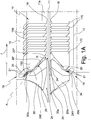
figure 1A represents a detail offigure 1 in an enlarged scale; -
figure 2 schematically represents another possible embodiment of the inletting and agitation means of the electrolytic solution of an apparatus according to the present invention suitable, in particular, for advancing the metal semi-finished product at low-speed lines (speed < 1 m/s); -
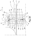
figure 2A represents a detail offigure 2 in an enlarged scale; -
figure 3 represents a schematic longitudinal section of an apparatus according to the present invention of the "horizontal" type; -
figure 4 is a section of the apparatus offigure 3 according to the plane IV-IV; -
figures 5A and 5B respectively show the details VA and VB offigure 3 in an enlarged scale; -
figure 5C shows an alternative embodiment of the detail offigure 5A or 5B in an enlarged scale; -
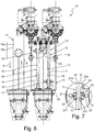
figure 6 represents a schematic longitudinal section of an apparatus according to the present invention of the "vertical" type; -
figure 7 shows the detail VII offigure 6 in an enlarged scale. - With reference to the attached figures, it is illustrated an apparatus for the surface electrolytic treatment in continuous of metal semi-finished products, in particular flat metal semi-finished products, wholly indicated with 10.
- The
apparatus 10 is applicable for carrying out surface electrolytic treatments in continuous and by so-called "immersion", i.e. wherein the metalsemi-finished product 11 advances continuously in atank 12 containing an electrolytic solution SE in which are immersed both thesemi-finished product 11 itself and the electrodes arranged opposite to each other and between which thesemi-finished product 11 is made to pass and which, in the case in which thesemi-finished product 11 is flat, are arranged at the opposite faces thereof. - By surface electrolytic treatment it is meant, for example, a degreasing, pickling, passivation, coating, galvanization, deposition or similar treatment.
- By metal semi-finished product it is meant to indicate in particular a flat metal semi-finished product, i.e. a continuous two-dimensional semi-finished product of the type of a plate, a strip, a billet or similar that has two opposite plane faces; although the possibility of applying the
apparatus 10 according to the present invention also for treatments of one-dimensional continuous semi-finished products such as wires, rods or wire rods, is not excluded. - In the attached figures the metal
semi-finished product 11 is a flat metal semi-finished product and consists of a continuous strip of metal, typically steel, which has twoopposite faces - With reference to the figures, the
apparatus 10 comprises acontainment tank 12 containing the electrolytic solution SE and inside which thesemi-finished product 11 is made to pass in continuous along a direction and in the advancing sense indicated by the arrow F. - The
apparatus 10 also comprises immersion means 13 for immersing thesemi-finished product 11 in the electrolytic solution SE and at least one pair ofelectrodes 14 opposite to each other and between which thesemi-finished product 11 is made to pass in continuous. - Preferably, there is a plurality of pairs of
electrodes 14 that follow one another along the advancing path of thesemi-finished product 11. - Each pair of
electrodes 14 comprises at least onefirst electrode 15 facing one of the twofaces semi-finished product 11 and at a defined distance from the latter so as to define afirst interspace 16 and at least onesecond electrode 17 facing the other one of the twofaces semi-finished product 11 and at a defined distance from the latter so as to define asecond interspace 18. In the case in which thesemi-finished product 11 is of the type of a wire, a rod or a wire rod, thefirst electrode 15 and thesecond electrode 17 are opposite to each other and face the opposite faces of the advancement plane of thesemi-finished product 11 at a predefined distance from thesemi-finished product 11. For the sake of simplicity, in the rest of the description reference will be made to the case in which thesemi-finished product 11 is of the flat type and to the opposite plane faces 11a, 11b thereof. - The
first electrode 15 and thesecond electrode 17 are both immersed in the electrolytic solution SE and are associable with an electric power supply group that is not represented, since it is of the known type. - Each pair of
electrodes 14, moreover, has, with respect to the direction and to the advancing sense F of thesemi-finished product 11, an inlet end schematically represented by theline 14a and an outlet end schematically indicated by theline 14b. - The
apparatus 10 also comprises inletting and agitation means 19 of the electrolytic solution SE contained in thetank 12. - According to a characteristic feature of the present invention, the inletting and agitation means 19 comprise at least one
duct 20 that is arranged at at least one of the pairs ofelectrodes 14, preferably at each of them, and that is associated with and in fluid communication with at least onenozzle 21, preferably with a plurality ofnozzles 21, for inletting the electrolytic solution SE fed byfeeding means 22. Usefully, for each pair ofelectrodes 14 there is a pair ofducts 20 each of which is associated withrespective nozzles 21 and that are symmetrically arranged with respect to the advancement plane of thesemi-finished product 11, so as not to alter the movement thereof. - In greater detail, each
duct 20 has adelivery end 20a that faces one of the twofaces first interspace 16 or thesecond interspace 18 and asuction end 20b that is opposite thedelivery end 20a, open and immersed in the electrolytic solution SE. Thesuction end 20b is axially opposite thedelivery end 20a or in any case opposite the latter with respect to the axial development of theduct 20, in particular the development of theduct 20 considered on a plane orthogonal to the advancement plane of the semi-finished product and parallel to the advancing direction thereof. - Advantageously, both the
suction end 20b and thedelivery end 20a extend by the entire width of thesemi-finished product 11 and thenozzles 21 are arranged in succession one after the other for the entire extension of thesuction end 20b of therespective duct 20. - Each
nozzle 21 is arranged so that itsoutlet mouth 21a is arranged at and in fluid communication with thesuction end 20b of thecorresponding duct 20. - The
outlet mouth 21a of thenozzles 21 can be arranged at the inlet of thesuction end 20b of therespective duct 20 or downstream thereof towards the inside of therespective duct 20. - The
suction end 20b of eachduct 20 remains open and in fluid communication with the inside of thetank 12 and immersed in the electrolytic solution SE without being occluded by thenozzles 21 arranged at it. In particular, thesuction end 20b of eachduct 20 has a portion that is free from the at least onenozzle 21 and that is immersed in the electrolytic solution contained in thetank 12. In this way, the jet of electrolytic solution that is emitted by eachnozzle 21 draws, from the inside of thetank 12, an electrolytic solution current that enters therespective duct 20 through itssuction end 20b, i.e. through the portion of such asuction end 20b that is free (i.e. not occupied by the at least one nozzle 21). The electrolytic solution current thus drawn from the inside of thetank 12 towards the inside of eachduct 20 mixes with the jet of electrolytic solution emitted by eachnozzle 21 associated with theduct 20 itself and exit from thedelivery end 20a of the latter at thefirst interspace 16 or thesecond interspace 18, where it creates turbulence and mixing of the electrolytic solution SE promoting the removal and taking away of the residues and treatment waste products in the form of scales, powders or gases, as well as the removal of the heat that possibly is generated, from thesemi-finished product 11, from thefirst electrode 15, and from thesecond electrode 17. - There is thus a "flow rate multiplication" effect with respect to that emitted by the
single nozzles 21 without using further energy beyond that necessary to operate the feeding means 22. - In a preferred embodiment, each
duct 20 comprises a converging section 20' converging towards thedelivery end 20a and that originates from thesuction end 20b. - The
nozzles 21 associated with eachduct 20 are arranged so that theiroutlet mouth 21a is at or upstream of the smaller section of the converging section 20'. - Advantageously, downstream, with respect to the direction of the current of the electrolytic solution that flows through the
duct 20, of the converging section 20' there is a divergingsection 20" diverging towards thedelivery end 20a. Such a divergingsection 20" is joined to the converging section 20' and makes it possible to increase the pressure of the current deriving from the mixing of the jets of electrolytic solution emitted by thenozzles 21 and of the electrolytic solution current sucked from the inside of thetank 12 through thesuction end 20b of theduct 20. Eachduct 20, that is, has, seen in section on a plane orthogonal to the advancement plane of thesemi-finished product 11 and parallel to the advancing direction F thereof, the shape of a convergent - divergent Venturi tube. - In a possible embodiment, moreover, each
duct 20 can comprise a deviator section 20''' that opens at itsdelivery end 20a to deviate the electrolytic solution current that flows through it along a direction having a non-null component on the advancement plane of thesemi-finished product 11 and in the same advancing sense thereof. In practice, the direction along which the electrolytic solution current exiting eachduct 20 is deviated hits the advancement plane of thesemi-finished product 11 with a non-null incidence angle α (figures 5A-5C ). - Alternatively or in addition to the provision of the deviator section 20''', each
duct 20, considered in section along a plane orthogonal to the advancement plane of thesemi-finished product 11 and parallel to the advancing direction F thereof, has a longitudinal axis or axial development A incident such an advancement plane with an incidence angle α ≤ 90° as a function of the forward speed of thesemi-finished product 11 as will be described later on. - In function of the type of surface treatment to be carried out and, in particular, the forward speed of the
semi-finished product 11, as will be described later on, theduct 20 associated with each pair ofelectrodes 14 can be arranged at one of the two opposite ends of the latter, advantageously at theinlet end 14a thereof, or in a position intermediate to them. - In a preferred and advantageous embodiment, the
first electrode 15 and thesecond electrode 17 of each pair ofelectrodes 14 has a "discontinuous" structure and comprises a plurality of rods or plates 150,170 which extend by the width of thesemi-finished product 11 and which are arranged parallel to each other and spaced at a defined distance from each other to form openings for taking away and removing the residues and the treatment waste products. The rods orplates semi-finished product 11 and incident the advancing direction F thereof. - In this case, each
duct 20 is advantageously delimited by a pair of such rods orplates electrodes 14, by one of such rods orplates plate 23 made of electrically insulating material. - It is clear that in this case the
plates duct 20 can have an increased thickness and are arranged with its face having greatest extension parallel to a plane orthogonal to the advancement plane of thesemi-finished product 11 and incident the advancing direction F. - In this case, the faces of the two adjacent rods or plates 150,170 or of such a rod or plate 150,170 and of the facing rod or
plate 23 made of electrically insulating material facing one another define the walls of theduct 20 and are shaped so as to define the converging section 20', the divergingsection 20" and the deviator section 20''' thereof, if present. Alternatively, each of thefirst electrode 15 and thesecond electrode 17 comprises aplate semi-finished product 11 and which has at least one slot 251,271 that extends by the width of thesemi-finished product 11 and at which therespective duct 20 is defined or associated (figures 6 and 7 ). - According to a further characteristic feature of the present invention, at the
inlet end 14a of each pair ofelectrodes 14 there is anentrance 24 for guiding thesemi-finished product 11 between thefirst electrode 15 and thesecond electrode 17. - The
entrance 24 is immersed in the electrolytic solution SE and, seen on a plane orthogonal to the advancement plane of thesemi-finished product 11 and parallel to the advancing direction F thereof, has a first section 24' converging in the advancing sense of thesemi-finished product 11. - Downstream of the first section 24' there is a second section 24'' for joining with the surfaces of the
first electrode 15 and of thesecond electrode 17 of the respective pair ofelectrodes 14 facing therespective face semi-finished product 11. - The second section 24'' can have a constant or diverging cross section.
- The
entrance 24 has the opposite ends, and of these, in particular, the inlet end defined at the larger cross section of the first section 24', open and immersed in the electrolytic solution SE. - As a consequence of the forward movement of the
semi-finished product 11 through theentrance 24, an electrolytic solution current is sucked into theentrance 24 through its inlet end. Such a current flows towards thefirst interspace 16 and thesecond interspace 18 where it contributes creating turbulence to promote the mixing of the electrolytic solution and taking away the residues, waste products and gases that generate from thesemi-finished product 11 and from the electrodes of the pair ofelectrodes 14 as a consequence of their treatment. - The
entrance 24 is made of electrically insulating material and consists of afirst body 240 and of asecond body 241 which extend by the width of thesemi-finished product 11 and which are conformed and arranged symmetrically with respect to the advancement plane of thesemi-finished product 11 itself. - The feeding means 22 that feed the electrolytic solution SE to the
nozzles 21 comprise pump means 26 that suck from atank 27 of fresh or regenerated electrolytic solution or from a recirculation line of the electrolytic solution present in thetank 12 and not shown. - At each pair of
electrodes 14, thetank 12 has ahopper 28 which is provided on its bottom with discharge means 29 for discharging waste materials produced during the surface electrolytic treatment, the discharge means being connected to a collection andremoval line 30, as described for example inWO2011/039596 here referred to. - The immersion means 13 comprise at least one
deflector roller 31 arranged at the inlet end of thetank 12, at least onedeflector roller 32 at the outlet end of thetank 12 and at least one immersingroller 33 for immersing thesemi-finished product 11 in the electrolytic solution and that is interposed between theinlet deflector roller 31 and theoutlet deflector roller 32. - Upstream and downstream, with respect to the advancing sense F of the
semi-finished product 11, of each immersingroller 33 there is a respective pair ofelectrodes 14, as described inWO2011/039596 here referred to. - The attached figures show different embodiments of an
apparatus 10 according to the present invention that will now be described in greater detail. -
Figures 1 and1A schematically show anapparatus 10 of the "horizontal" type suitable for treatments of thesemi-finished product 11 advancing at high-speed, i.e. at speeds greater than 1m/s. - Such figures show a single pair of
electrodes 14 arranged downstream of the immersingroller 33 at the inlet of thetank 12. - At the
inlet end 14a of the pair ofelectrodes 14 there is theentrance 24; the pair ofelectrodes 14 and theentrance 24 are immersed in the electrolytic solution SE contained in thetank 12. - Each of the
first electrode 15 and thesecond electrode 17 consists of a plurality of plates 150,170 which extend by the width of thesemi-finished product 11 and which are arranged parallel to each other on planes orthogonal to the advancement plane of thesemi-finished product 11 and incident the advancing direction F of thesemi-finished product 11 spaced apart from one another so as to define openings for taking away the waste, the residues and the gases that generate from the surface treatment. - Between the first two adjacent plates 150,170 of each of the
first electrode 15 and the second electrode 17 arespective duct 20 of the convergent-divergent type (of the "Venturi" type) is defined having thedelivery end 20a respectively facing thefirst interspace 16 and thesecond interspace 18 and thesuction end 20b open and immersed in the electrolytic solution SE contained in thetank 12. - The two
ducts 20 are configured and arranged symmetrically with respect to the advancement plane of thesemi-finished product 11. - The diverging section of the two
ducts 20 has an axis A incident the advancement plane of thesemi-finished product 11 with an incidence angle α < 90° in the advancing sense F of thesemi-finished product 11. The incidence angle α is advantageously comprised between 20° and 90° and preferably equal to 45°. - At the
suction end 20b of each of the twoducts 20 there is a plurality ofnozzles 21 which are arranged in succession along the width of thesemi-finished product 11 and fed by the feeding means 22 through acommon manifold 34. Thenozzles 21 are arranged so that a portion of thesuction end 20b of eachduct 20 is free, open and immersed in the electrolytic solution present in thetank 12. As an alternative to a plurality ofnozzles 21, there could be a single nozzle of the blade type. - The solution schematised in
figures 2 and2A differs from the one shown infigures 1 and1A , in absence of theentrance 24 and in the different arrangement and orientation of theducts 20. - The
ducts 20, indeed, are defined in an intermediate zone of the pair ofelectrodes 14 or rather in an intermediate zone of thefirst electrode 15 and of thesecond electrode 17. - Each
duct 20, indeed, is delimited by a pair ofsuccessive plates first electrode 15 and of thesecond electrode 17. - Each
duct 20 has a longitudinal axis A orthogonal to the advancement plane of the semi-finished product 11 (incidence angle α = 90°). - Such an embodiment of the
apparatus 10 is suitable for treatments of thesemi-finished product 11 advancing at low-speed (<1m/s). -
Figures 3 to 5B show anapparatus 10 of the "horizontal" type that reproduces the characteristics of the configuration and of the arrangement of thetank 12 as described inWO2011/039596 . - The
tank 12, indeed, has amain treatment portion 120 delimited at the opposite ends by aninlet portion 121 and by anoutlet portion 122 that are separated from the internal space of themain treatment portion 120 by correspondingwalls 123. - The electrolytic solution SE is contained in just the
main treatment portion 120. - At the
inlet portion 121 there is aninlet deflector roller 31 and at theoutlet portion 122 there is anoutlet deflector roller 32. - Between the
inlet deflector roller 31 and theoutlet deflector roller 32 there is a pair of immersingrollers 33 that push thesemi-finished product 11, which moves forward along the direction and in the sense F, towards the bottom of thetank 12 keeping it immersed in the electrolytic solution SE. - Upstream and downstream of each immersing
roller 33 there is a respective pair ofelectrodes 14. - At each pair of
electrodes 14 thetank 12, i.e. themain treatment portion 120 thereof, is conformed like ahopper 28 which is provided with dischargingmeans 29 connected to a collection andremoval line 30. - As shown in
figures 5A and 5B both thefirst electrode 15 and thesecond electrode 17 of each pair ofelectrodes 14 consists of a plurality of plates, 150 and 170 respectively, which extend with their length in the direction of the width of thesemi-finished product 11 and which are arranged parallel to each other on planes orthogonal to the advancement plane of thesemi-finished product 11 and incident the advancing direction F and which are spaced apart from one another to define openings to facilitate the mixing of the electrolytic solution and the removal of waste, residues and gases both from thesemi-finished product 11 and from the plates 150,170 themselves. - At the
inlet end 14a of each pair ofelectrodes 14 there is a pair ofducts 20 configured and arranged symmetrically with respect to the advancement plane of thesemi-finished product 11. - Each of the two
ducts 20 is delimited on one side by the respective head plate 150', 170' respectively of thefirst electrode 15 and of thesecond electrode 17 and on the other side by aplate 23 made of electrically insulating material. - Each of the two
ducts 20 has a converging section 20' that originates at therespective suction end 20b and that is joined to a diverging section ordiffusor 20" which extends in a deviator section 20''' that opens at therespective delivery end 20a. - The two
ducts 20 have thedelivery end 20a arranged respectively at thefirst interspace 16 and at thesecond interspace 18. - The deviator section 20''' is inclined according to a direction incident the advancement plane of the
semi-finished product 11 with an incidence angle α <90° so as to direct the electrolytic solution current exiting theducts 20 in the same advancing sense of the semi-finished product 11 (equicurrent). - The plates 150,170 are supported by
armatures 35 anchored to thetank 12. - At the
suction end 20b of each of the twoducts 20 there is a plurality ofnozzles 21 which are arranged in succession one after the other for the entire width of thesemi-finished product 11. - The
nozzles 21 derive from acommon manifold 34 fed by the feeding means 22. - Also in this case, the
nozzles 21 are arranged so that a portion of thesuction end 20b of eachduct 20 is free, open and immersed in the electrolytic solution present in thetank 12. Also in this case, instead of a plurality ofnozzles 21 there could be a single nozzle of the blade type. - In a possible alternative embodiment represented in
figure 5C , theducts 20 defined at theinlet end 14a of each pair ofelectrodes 14 are delimited by the head plate 150', 170' of thefirst electrode 15 and of thesecond electrode 17 and by the plate immediately adjacent to it. - In this case, the head plate 150', 170' is supported by a
protection 36 made of electrically insulating material. - The
apparatus 10 according tofigures 3 to 5C can be advantageously applied to carry out degreasing treatments with alkaline electrolytic solution SE kept at temperatures comprised between 20°C and 90°C with the four pairs ofelectrodes 14 having "grid-to-grid" configuration fed in direct current (DC) with alternating polarity according to the sequence cathode-anode-anode-cathode, so that thesemi-finished product 11, in particular if made of steel, comes out with anodic polarity so as to avoid it absorbing hydrogen. Advantageously, in the configuration of theapparatus 10 shown infigures 3 to 5C , the distance between each pair ofelectrodes 14 and the adjacent immersingroller 33 and measured between the end of the anode and between the projection of the axis of the immersing roller on the advancement plane of thesemi-finished product 11 is comprised between 150 mm and 1500 mm, whereas the distance between two immersingrollers 33 is comprised between 1500 mm and 3500 mm for degreasing treatments and between 2000 mm and 7000 for pickling, passivation or electrodeposition treatments. - The height of the first and
second interspace second electrode respective face semi-finished product 11 and thesame face semi-finished product 11 so as to minimise the drop in voltage in solution. This makes it possible to reduce the voltage applied to the electrodes of each pair ofelectrodes 14 with a consequent decrease in energy consumption and, moreover, to reduce the overall bulk of theapparatus 10 to the benefit of the layout of the plant in which it is inserted. - Such a configuration makes it possible to apply a current density comprised between 40 A/dm2 and 150 A/dm2 with charge density always >1C/dm2, in the case of degreasing treatments, and between 8 A/dm2 and 50 A/dm2, in the case of pickling treatments with exposure times comprised between 1s and 15s, against, respectively, usually known values of 15-20 A/dm2 and of 8-14 A/dm2. In the case of electrodeposition treatments, on the other hand, the current density is comprised between 5 A/dm2 and 100 A/dm2 with variable exposure times as a function of the number of pairs of electrodes present and the thickness of the coating that is wished to be obtained.
- Laboratory tests have indeed demonstrated that thanks to the particular "discontinuous" structure of the electrodes and to the presence of inletting and agitation means 19 consisting in practice of "Venturi"
ducts 20 associated with a respective plurality ofnozzles 21 for inletting electrolytic solution, it is possible to increase the current density up to 4-5 times the conventional densities maintaining a good evacuation of the gases and of the treatment waste and a good degree of cleaning of the electrodes themselves. The efficiency of cleaning of thesemi-finished products 11 can thus increase by 10-25% and even up to 50% with respect to conventional treatments and the electrical energy consumption can thus be reduced by 20-30%. -
Figures 6 and 7 show anapparatus 10 of the "vertical" type, i.e. in which thesemi-finished product 11 follows a path along vertical planes with a descending branch and an ascending branch inside eachtank 12. - At the opposite faces 11a,11b of the descending branch and the ascending branch of the
semi-finished product 11 there is a respective pair ofelectrodes 14, thefirst electrode 15 andsecond electrode 17 of which consist of plates 250,270 that are flat and parallel to thefaces - At the
inlet end 14a of each pair ofelectrodes 14 there is a respective pair ofducts 20 configured and arranged symmetrically with respect to the advancement plane of thesemi-finished product 11. - Each
duct 20 is obtained at aslot - Advantageously, the distance between the immersing
roller 33 and the inlet andoutlet deflecting rollers - Also in this case the
tank 12 advantageously is configured like ahopper 28 which is arranged below the pairs ofelectrodes 14 and which is provided with dischargingmeans 29 associated with an evacuation andremoval line 30. - In light of the attached figures and the previous description the person skilled in the art will have no difficulty understanding the operation of the
apparatus 10 object of the present invention. - The
semi-finished product 11 is made to pass inside thetank 12 at a defined advancement speed and is kept immersed inside the electrolytic solution SE by means of the immersingrollers 33. - Direct current (DC), alternating current (AC) or mixed current is applied to the pairs of
electrodes 14 in function of the type of treatment to be carried out and the electrolytic solution SE used for it. - While the
semi-finished product 11 advances between thefirst electrode 15 and thesecond electrode 17 of each pair ofelectrodes 14, the inletting and agitation means 19 are active so as to keep the electrolytic solution SE homogeneous and agitated in particular at thefirst interspace 16 and thesecond interspace 18 so as to promote the removal therefrom of the waste and of the treatment residues and of the gases that are generated during it. - In particular, the jets of electrolytic solution injected by each
nozzle 21 into therespective duct 20, or rather the depression created by them, draw from the inside of thetank 12 further electrolytic solution SE that is sucked into theduct 20 through thesuction end 20b of theduct 20 itself (or rather through the portion of such asuction end 20b that is free, i.e. not occupied by thenozzles 21 themselves) where it mixes with the jets inlet there by thenozzles 21. - The electrolytic solution current that comes out from the
delivery end 20a of eachduct 20 thus has an amplified flow rate with respect to that corresponding to the sum of the jets therein injected by eachnozzle 21 without any further energy use to create it besides that necessary for the operation of the pump means 26 that feed thenozzles 21 and already usually used. - The electrolytic solution current inlet by each
duct 20 at respectively thefirst interspace 16 and thesecond interspace 18 creates a turbulence such as to promote, together with the "discontinuous" conformation or the "vertical" arrangement of thefirst electrode 15 and of thesecond electrode 17, the removal of the residues and of the treatment wastes, of the gases that are generated during the course of the treatment itself and the removal of the heat possibly produced. - This allows, on the one hand, to increase the current density even up to 5 times the usual current densities, whilst still ensuring effective cleaning of the electrodes, and on the other hand to increase the efficiency of the treatment even by up to 50% with respect to usual treatments with energy consumption reduced even by 30% with respect to conventional treatments.
- Such effects are then amplified in the case in which at the inlet end of each pair of
electrodes 14 there is a guidingentrance 24 also configured like a "Venturi" and which, following the motion of thesemi-finished product 11, draws an electrolytic solution current that is inlet into thefirst interspace 16 and into thesecond interspace 18 creating further turbulence. - The symmetrical configuration and arrangement of the
ducts 20 contributes keeping in position and stabilizing thesemi-finished product 11 during its forward motion. - The apparatus for the surface electrolytic treatment in continuous of metal semi-finished products, in particular flat metal semi-finished products, thus conceived can undergo numerous modifications and variants, moreover, all of the details can be replaced by technically equivalent elements as long as they are within the scope of the appended claims. In practice, the materials used, as well as the sizes, can be whatever according to the technical requirements.
Claims (15)
- Apparatus (10) for the surface electrolytic treatment in continuous of metal semi-finished products, in particular flat metal semi-finished products, comprising:- a containment tank (12) containing an electrolytic solution (SE) and inside which a metal semi-finished product (11) is made to advance in continuous along an advancement plane,- immersion means (31, 32, 33) for immersing said metal semi-finished product (11) into said electrolytic solution,- at least one pair of electrodes (14) opposite to each other and between which said metal semi-finished product (11) is made to advance in continuous, wherein said pair of electrodes (14) comprises at least one first electrode (15) facing one of the two opposite plane faces of said advancement plane and at a defined distance from said semi-finished product (11) so as to define with it a first interspace (16) and at least one second electrode (17) facing the other one of said two opposite plane faces of said advancement plane and at a defined distance from said semi-finished product (11) so as to define with it a second interspace (18) and wherein said at least one pair of electrodes (14) is immersed in said electrolytic solution and is associable with an electric power supply group,- inletting and agitation means (19) for inletting and agitating said electrolytic solution in said tank (12), characterised in that- said inletting and agitation means (19) comprise at least one duct (20) arranged at said at least one pair of electrodes (14) and provided with a delivery end (20a) facing one of said two opposite plane faces at respectively said first interspace (16) or said second interspace (18) and with a suction end (20b) that is opposite to said delivery end (20a) and open and immersed in the electrolytic solution contained in said tank (12), and at least one inletting nozzle (21) for inletting said electrolytic solution which is associable with feeding means (22) of said electrolytic solution and the outlet mouth (21a) of which is arranged at said suction end (20b) of said at least one duct (20), wherein said suction end (20b) of said at least one duct (20) has a portion that is free from said at least one nozzle (21) and that is immersed in the electrolytic solution contained in said tank (12) and wherein the jet of electrolytic solution emitted by said at least one nozzle (21) draws, from the inside of said tank (12), an electrolytic solution current that enters said at least one duct (20) through said suction end portion (20b), said jet and said current mixed together exiting from said delivery end (20a) at said first interspace (16) or said second interspace (18).
- Apparatus (10) according to claim 1, characterized in that said at least one duct (20) comprises a section converging (20') towards said delivery end (20a).
- Apparatus (10) according to claim 2, characterized in that said at least one duct (20) comprises a section diverging (20") towards said delivery end (20a) that is arranged downstream, with respect to the sense of the electrolytic solution current which flows through said at least one duct, of said converging section (20').
- Apparatus (10) according to one or more of the previous claims, characterized in that said at least one duct (20) comprises a deviator section (20''') which opens at said delivery end (20a) for deviating the electrolytic solution current that flows through said at least one duct (20) along a direction having a non-null component on the advancement plane of said metal semi-finished product (11) and in the same advancing sense of said metal semi-finished product (11) .
- Apparatus (10) according to one or more of the previous claims, characterized in that considering said at least one duct (20) in section along a plane orthogonal to the advancement plane of said metal semi-finished product (11) and parallel to the advancing direction (F) of said metal semi-finished product, the axial development (A) of said at least one duct is incident said advancement plane with an incidence angle (α) comprised between 20° and 90°.
- Apparatus (10) according to one or more of the previous claims, characterized in that said delivery end (20a) and said suction end (20b) of said at least one duct (20) extend by the width of said metal semi-finished product (11), wherein said inletting and agitation means (19) comprise a plurality of said nozzles (21) arranged in succession along the width of said metal semi-finished product (11).
- Apparatus (10) according to one or more of the previous claims, characterized in that said at least one pair of electrodes (14) has, with respect to the advancing sense (F) of said metal semi-finished product (11), an inlet end (14a) and an outlet end (14b), wherein said at least one duct (20) is defined at said inlet end (14a).
- Apparatus (10) according to one or more of the previous claims, characterized in that said at least one pair of electrodes (14) has, with respect to the advancing sense (F) of said metal semi-finished product (11), an inlet end (14a) and an outlet end (14b), wherein said at least one duct (20) is defined at an intermediate zone between said inlet end (14a) and said outlet end (14b).
- Apparatus (10) according to one or more of the previous claims, characterized in that each of said first electrode (15) and said second electrode (17) comprises a plurality of rods or plates (150, 170) which extend by the width of said metal semi-finished product (11) and which are arranged parallel to each other and spaced at a definite distance from each other so as to form openings.
- Apparatus (10) according to claim 9, characterized in that said at least one duct (20) is delimited by a pair of said rods or plates (150, 170; 150', 170') adjacent each other or by one of said rods or plates and by a facing rod or plate (23) made of electrically insulating material, the faces of said two adjacent rods or plates (150, 170; 150', 170') or of said one rod or plate (150, 170; 150', 170') and of said facing rod or plate (23) made of electrically insulating material facing each other defining the walls of said at least one duct (20).
- Apparatus (10) according to one or more of claims 1 to 8, characterized in that each of said first electrode (15) and said second electrode (17) comprises a plate (250, 270) which extends parallel to said advancement plane of said metal semi-finished product (11) and which has at least one slot (251, 271) that extends by the width of said metal semi-finished product (11), wherein said at least one duct (20) is defined at said slot.
- Apparatus (10) according to one or more of the previous claims, characterized in that said inletting and agitation means (19) comprise at least one pair of said ducts (20) arranged symmetrically with respect to the advancement plane of said metal semi-finished product (11).
- Apparatus (10) according to one or more of the previous claims, characterized in that said at least one pair of electrodes (14) has, with respect to the advancing sense of said metal semi-finished product (11), an inlet end (14a) and an outlet end (14b) and in that at said inlet end (14a) a guiding entrance (24) for guiding said metal semi-finished product (11) is present between said first electrode (15) and said second electrode (17), wherein said guiding entrance (24) is immersed in said electrolytic solution (SE) and, seen on a plane orthogonal to the advancement plane of said metal semi-finished product and parallel to the advancing direction (F) of said metal semi-finished product (11), has a first converging section (24') in the advancing sense (F) of said metal semi-finished product (11) and crossed by said metal semi-finished product.
- Apparatus (10) according to claim 13, characterized in that said guiding entrance (24) has downstream, with respect to the advancing sense (F) of said metal semi-finished product (11), of said first converging section (24') a second diverging or constant cross-section portion (24") which connects respectively with the surface of said first electrode (15) and of said second electrode (17) facing the respective plane face of said advancement plane of metal semi-finished product.
- Apparatus (10) according to one or more of the previous claims, characterized in that said immersion means comprise at least one deflector roller (31) at the inlet end of said tank, at least one deflector roller (32) at the outlet end of said tank and at least one immersing roller (33) of said metal semi-finished product (11) in said electrolytic solution (SE) which is interposed between said inlet deflector roller (31) and said outlet deflector roller (32), wherein upstream and/or downstream with respect to the advancing sense (F) of said metal semi-finished product (11), of said at least one immersing roller (33) a respective said pair of electrodes (14) is present.
Applications Claiming Priority (2)
| Application Number | Priority Date | Filing Date | Title |
|---|---|---|---|
| IT000497A ITMI20130497A1 (en) | 2013-03-29 | 2013-03-29 | EQUIPMENT FOR THE CONTINUOUS SURFACE ELECTROLYTIC TREATMENT OF METALLIC SEMI-FINISHED PRODUCTS, IN PARTICULAR FLAT METALLIC SEMI-FINISHED PRODUCTS. |
| PCT/IB2014/060211 WO2014155331A1 (en) | 2013-03-29 | 2014-03-27 | Apparatus for the surface electrolytic treatment in continuous of metal semi-finished products, in particular flat metal semi-finished products |
Publications (2)
| Publication Number | Publication Date |
|---|---|
| EP2978880A1 EP2978880A1 (en) | 2016-02-03 |
| EP2978880B1 true EP2978880B1 (en) | 2018-09-12 |
Family
ID=48444517
Family Applications (1)
| Application Number | Title | Priority Date | Filing Date |
|---|---|---|---|
| EP14727906.1A Active EP2978880B1 (en) | 2013-03-29 | 2014-03-27 | Apparatus for the surface electrolytic treatment in continuous of metal semi-finished products, in particular flat metal semi-finished products |
Country Status (4)
| Country | Link |
|---|---|
| EP (1) | EP2978880B1 (en) |
| CN (1) | CN105051265B (en) |
| IT (1) | ITMI20130497A1 (en) |
| WO (1) | WO2014155331A1 (en) |
Families Citing this family (1)
| Publication number | Priority date | Publication date | Assignee | Title |
|---|---|---|---|---|
| EP3825445B1 (en) * | 2019-11-22 | 2025-08-20 | Semsysco GmbH | Distribution body for a process fluid for chemical and/or electrolytic surface treatment of a substrate |
Family Cites Families (14)
| Publication number | Priority date | Publication date | Assignee | Title |
|---|---|---|---|---|
| US4035256A (en) | 1976-04-19 | 1977-07-12 | United States Steel Corporation | Process for electrolytic removal of lubricants from steel strip |
| IT1227203B (en) * | 1988-08-18 | 1991-03-27 | Techint Spa | HORIZONTAL ELECTROLYTIC METALLIZATION PLANT, WITH SOLUBLE ANODES, FOR CONTINUOUS ELECTROLYTIC TREATMENT OF STEEL BELTS ON ONE OR TWO SIDES, AND PROCEDURE |
| NL8802353A (en) * | 1988-09-23 | 1990-04-17 | Hoogovens Groep Bv | METHOD FOR SINGLE SIDED ELECTROLYTIC COATING OF A MOVING METAL BELT |
| EP0504952A1 (en) * | 1991-02-15 | 1992-09-23 | The Procter & Gamble Company | Stable liquid amidoperoxyacid bleach |
| DE4425854C1 (en) * | 1994-07-07 | 1995-11-09 | Mannesmann Ag | Electrolytic surface treatment process and plant for carrying out the process |
| JP2892595B2 (en) | 1994-12-27 | 1999-05-17 | 川崎製鉄株式会社 | Method and apparatus for cleaning metal strip after cold rolling |
| JP3299451B2 (en) * | 1996-09-30 | 2002-07-08 | 新日本製鐵株式会社 | Vertical electrolytic device |
| JP3780392B2 (en) | 1996-12-18 | 2006-05-31 | 株式会社ホタニ | Strip cleaning method and cleaning apparatus |
| ES2172084T3 (en) | 1997-04-10 | 2002-09-16 | Hotani Kk | METHOD AND APPLIANCE FOR CLEANING METAL BANDS. |
| TW369475B (en) | 1997-06-18 | 1999-09-11 | Jsp Corp | Production apparatus of expansion-molded article, auxiliary member for transfer of foamed particles and production method of expansion-molded article |
| JP3808239B2 (en) | 1999-06-09 | 2006-08-09 | Jfeスチール株式会社 | Steel strip degreasing method |
| IT1318919B1 (en) * | 2000-09-22 | 2003-09-19 | Danieli Hi Tech Gmbh | PROCESS AND DEVICE FOR SURFACE ELECTROLYTIC TREATMENT OF METAL TAPES. |
| JP2009221571A (en) * | 2008-03-18 | 2009-10-01 | Fujifilm Corp | Electrolytic treatment apparatus and electrolytic treatment method |
| IT1395853B1 (en) * | 2009-09-30 | 2012-10-26 | Tenova Spa | SURFACE PREPARATION GROUP FOR METALLIC TAPE PRODUCTION LINES |
-
2013
- 2013-03-29 IT IT000497A patent/ITMI20130497A1/en unknown
-
2014
- 2014-03-27 EP EP14727906.1A patent/EP2978880B1/en active Active
- 2014-03-27 WO PCT/IB2014/060211 patent/WO2014155331A1/en not_active Ceased
- 2014-03-27 CN CN201480018110.9A patent/CN105051265B/en active Active
Non-Patent Citations (1)
| Title |
|---|
| None * |
Also Published As
| Publication number | Publication date |
|---|---|
| CN105051265A (en) | 2015-11-11 |
| ITMI20130497A1 (en) | 2014-09-30 |
| EP2978880A1 (en) | 2016-02-03 |
| WO2014155331A1 (en) | 2014-10-02 |
| CN105051265B (en) | 2017-07-04 |
Similar Documents
| Publication | Publication Date | Title |
|---|---|---|
| CN109778288A (en) | A kind of roll-to-roll horizontal electroplating bath device | |
| US12188143B2 (en) | Electroplating device and electroplating system | |
| JPS59162298A (en) | High current density plating method of metallic strip | |
| JP4586423B2 (en) | Method for producing electroplated steel sheet | |
| US9534302B2 (en) | Device and method for post-treating a metal strip | |
| EP2978880A1 (en) | Apparatus for the surface electrolytic treatment in continuous of metal semi-finished products, in particular flat metal semi-finished products | |
| CN204602828U (en) | A kind of Novel cold rolling strip cleaning electrolytic cell | |
| CN104256866A (en) | Fruit and vegetable purifier combining washing and water catalyst | |
| CN217392036U (en) | Cable extruder head exhaust treatment device | |
| CN216731320U (en) | Surface treatment equipment for steel belt processing | |
| CN1166817C (en) | Pickling unit | |
| CA1277283C (en) | High-speed electrolysis cell for processing strip- shaped material | |
| US5584984A (en) | Method and apparatus for electrolytic treatment of a surface | |
| JPH08510012A (en) | Method and apparatus for pickling stainless steel | |
| CN208680207U (en) | A kind of extruder profile cooling device | |
| KR102663445B1 (en) | Method for processing objects and apparatus for carrying out this method | |
| US2196355A (en) | Means for circulating electrolyte in apparatus for the electrodeposition of metals | |
| JP2011225907A (en) | Apparatus for pickling metallic bar and method therefor | |
| CN219991765U (en) | A kind of non-contact horizontal electroplating equipment | |
| KR20130064613A (en) | Apparatus and method for treating surface of hot rolled strip | |
| JP6414037B2 (en) | Method for producing electroplating strip | |
| JP6603159B2 (en) | Descaling apparatus and descaling method | |
| KR101322042B1 (en) | Descaling apparatus | |
| ITMI20002072A1 (en) | PROCESS AND DEVICE FOR SURFACE ELECTROLYTIC TREATMENT OF METAL TAPES. | |
| KR940011009B1 (en) | Counter-current electrolyte injector and electrodeposition device using thereof |
Legal Events
| Date | Code | Title | Description |
|---|---|---|---|
| PUAI | Public reference made under article 153(3) epc to a published international application that has entered the european phase |
Free format text: ORIGINAL CODE: 0009012 |
|
| 17P | Request for examination filed |
Effective date: 20150820 |
|
| AK | Designated contracting states |
Kind code of ref document: A1 Designated state(s): AL AT BE BG CH CY CZ DE DK EE ES FI FR GB GR HR HU IE IS IT LI LT LU LV MC MK MT NL NO PL PT RO RS SE SI SK SM TR |
|
| AX | Request for extension of the european patent |
Extension state: BA ME |
|
| DAX | Request for extension of the european patent (deleted) | ||
| GRAP | Despatch of communication of intention to grant a patent |
Free format text: ORIGINAL CODE: EPIDOSNIGR1 |
|
| STAA | Information on the status of an ep patent application or granted ep patent |
Free format text: STATUS: GRANT OF PATENT IS INTENDED |
|
| INTG | Intention to grant announced |
Effective date: 20180322 |
|
| GRAS | Grant fee paid |
Free format text: ORIGINAL CODE: EPIDOSNIGR3 |
|
| GRAA | (expected) grant |
Free format text: ORIGINAL CODE: 0009210 |
|
| STAA | Information on the status of an ep patent application or granted ep patent |
Free format text: STATUS: THE PATENT HAS BEEN GRANTED |
|
| RIN1 | Information on inventor provided before grant (corrected) |
Inventor name: DULCETTI, ALESSANDRO Inventor name: MARTINES, STEFANO Inventor name: LEONARDI, FABIO Inventor name: GURRERI, BALDO |
|
| AK | Designated contracting states |
Kind code of ref document: B1 Designated state(s): AL AT BE BG CH CY CZ DE DK EE ES FI FR GB GR HR HU IE IS IT LI LT LU LV MC MK MT NL NO PL PT RO RS SE SI SK SM TR |
|
| REG | Reference to a national code |
Ref country code: GB Ref legal event code: FG4D |
|
| REG | Reference to a national code |
Ref country code: CH Ref legal event code: EP |
|
| REG | Reference to a national code |
Ref country code: IE Ref legal event code: FG4D |
|
| REG | Reference to a national code |
Ref country code: DE Ref legal event code: R096 Ref document number: 602014032240 Country of ref document: DE |
|
| REG | Reference to a national code |
Ref country code: AT Ref legal event code: REF Ref document number: 1040697 Country of ref document: AT Kind code of ref document: T Effective date: 20181015 |
|
| REG | Reference to a national code |
Ref country code: NL Ref legal event code: MP Effective date: 20180912 |
|
| REG | Reference to a national code |
Ref country code: LT Ref legal event code: MG4D |
|
| PG25 | Lapsed in a contracting state [announced via postgrant information from national office to epo] |
Ref country code: FI Free format text: LAPSE BECAUSE OF FAILURE TO SUBMIT A TRANSLATION OF THE DESCRIPTION OR TO PAY THE FEE WITHIN THE PRESCRIBED TIME-LIMIT Effective date: 20180912 Ref country code: RS Free format text: LAPSE BECAUSE OF FAILURE TO SUBMIT A TRANSLATION OF THE DESCRIPTION OR TO PAY THE FEE WITHIN THE PRESCRIBED TIME-LIMIT Effective date: 20180912 Ref country code: LT Free format text: LAPSE BECAUSE OF FAILURE TO SUBMIT A TRANSLATION OF THE DESCRIPTION OR TO PAY THE FEE WITHIN THE PRESCRIBED TIME-LIMIT Effective date: 20180912 Ref country code: BG Free format text: LAPSE BECAUSE OF FAILURE TO SUBMIT A TRANSLATION OF THE DESCRIPTION OR TO PAY THE FEE WITHIN THE PRESCRIBED TIME-LIMIT Effective date: 20181212 Ref country code: NO Free format text: LAPSE BECAUSE OF FAILURE TO SUBMIT A TRANSLATION OF THE DESCRIPTION OR TO PAY THE FEE WITHIN THE PRESCRIBED TIME-LIMIT Effective date: 20181212 Ref country code: GR Free format text: LAPSE BECAUSE OF FAILURE TO SUBMIT A TRANSLATION OF THE DESCRIPTION OR TO PAY THE FEE WITHIN THE PRESCRIBED TIME-LIMIT Effective date: 20181213 Ref country code: SE Free format text: LAPSE BECAUSE OF FAILURE TO SUBMIT A TRANSLATION OF THE DESCRIPTION OR TO PAY THE FEE WITHIN THE PRESCRIBED TIME-LIMIT Effective date: 20180912 |
|
| PG25 | Lapsed in a contracting state [announced via postgrant information from national office to epo] |
Ref country code: HR Free format text: LAPSE BECAUSE OF FAILURE TO SUBMIT A TRANSLATION OF THE DESCRIPTION OR TO PAY THE FEE WITHIN THE PRESCRIBED TIME-LIMIT Effective date: 20180912 Ref country code: LV Free format text: LAPSE BECAUSE OF FAILURE TO SUBMIT A TRANSLATION OF THE DESCRIPTION OR TO PAY THE FEE WITHIN THE PRESCRIBED TIME-LIMIT Effective date: 20180912 Ref country code: AL Free format text: LAPSE BECAUSE OF FAILURE TO SUBMIT A TRANSLATION OF THE DESCRIPTION OR TO PAY THE FEE WITHIN THE PRESCRIBED TIME-LIMIT Effective date: 20180912 |
|
| PG25 | Lapsed in a contracting state [announced via postgrant information from national office to epo] |
Ref country code: CZ Free format text: LAPSE BECAUSE OF FAILURE TO SUBMIT A TRANSLATION OF THE DESCRIPTION OR TO PAY THE FEE WITHIN THE PRESCRIBED TIME-LIMIT Effective date: 20180912 Ref country code: IS Free format text: LAPSE BECAUSE OF FAILURE TO SUBMIT A TRANSLATION OF THE DESCRIPTION OR TO PAY THE FEE WITHIN THE PRESCRIBED TIME-LIMIT Effective date: 20190112 Ref country code: PL Free format text: LAPSE BECAUSE OF FAILURE TO SUBMIT A TRANSLATION OF THE DESCRIPTION OR TO PAY THE FEE WITHIN THE PRESCRIBED TIME-LIMIT Effective date: 20180912 Ref country code: NL Free format text: LAPSE BECAUSE OF FAILURE TO SUBMIT A TRANSLATION OF THE DESCRIPTION OR TO PAY THE FEE WITHIN THE PRESCRIBED TIME-LIMIT Effective date: 20180912 Ref country code: EE Free format text: LAPSE BECAUSE OF FAILURE TO SUBMIT A TRANSLATION OF THE DESCRIPTION OR TO PAY THE FEE WITHIN THE PRESCRIBED TIME-LIMIT Effective date: 20180912 Ref country code: ES Free format text: LAPSE BECAUSE OF FAILURE TO SUBMIT A TRANSLATION OF THE DESCRIPTION OR TO PAY THE FEE WITHIN THE PRESCRIBED TIME-LIMIT Effective date: 20180912 Ref country code: RO Free format text: LAPSE BECAUSE OF FAILURE TO SUBMIT A TRANSLATION OF THE DESCRIPTION OR TO PAY THE FEE WITHIN THE PRESCRIBED TIME-LIMIT Effective date: 20180912 |
|
| PG25 | Lapsed in a contracting state [announced via postgrant information from national office to epo] |
Ref country code: PT Free format text: LAPSE BECAUSE OF FAILURE TO SUBMIT A TRANSLATION OF THE DESCRIPTION OR TO PAY THE FEE WITHIN THE PRESCRIBED TIME-LIMIT Effective date: 20190112 Ref country code: SM Free format text: LAPSE BECAUSE OF FAILURE TO SUBMIT A TRANSLATION OF THE DESCRIPTION OR TO PAY THE FEE WITHIN THE PRESCRIBED TIME-LIMIT Effective date: 20180912 Ref country code: SK Free format text: LAPSE BECAUSE OF FAILURE TO SUBMIT A TRANSLATION OF THE DESCRIPTION OR TO PAY THE FEE WITHIN THE PRESCRIBED TIME-LIMIT Effective date: 20180912 |
|
| REG | Reference to a national code |
Ref country code: DE Ref legal event code: R097 Ref document number: 602014032240 Country of ref document: DE |
|
| PLBE | No opposition filed within time limit |
Free format text: ORIGINAL CODE: 0009261 |
|
| STAA | Information on the status of an ep patent application or granted ep patent |
Free format text: STATUS: NO OPPOSITION FILED WITHIN TIME LIMIT |
|
| PG25 | Lapsed in a contracting state [announced via postgrant information from national office to epo] |
Ref country code: DK Free format text: LAPSE BECAUSE OF FAILURE TO SUBMIT A TRANSLATION OF THE DESCRIPTION OR TO PAY THE FEE WITHIN THE PRESCRIBED TIME-LIMIT Effective date: 20180912 |
|
| 26N | No opposition filed |
Effective date: 20190613 |
|
| PG25 | Lapsed in a contracting state [announced via postgrant information from national office to epo] |
Ref country code: SI Free format text: LAPSE BECAUSE OF FAILURE TO SUBMIT A TRANSLATION OF THE DESCRIPTION OR TO PAY THE FEE WITHIN THE PRESCRIBED TIME-LIMIT Effective date: 20180912 |
|
| PG25 | Lapsed in a contracting state [announced via postgrant information from national office to epo] |
Ref country code: MC Free format text: LAPSE BECAUSE OF FAILURE TO SUBMIT A TRANSLATION OF THE DESCRIPTION OR TO PAY THE FEE WITHIN THE PRESCRIBED TIME-LIMIT Effective date: 20180912 |
|
| REG | Reference to a national code |
Ref country code: CH Ref legal event code: PL |
|
| GBPC | Gb: european patent ceased through non-payment of renewal fee |
Effective date: 20190327 |
|
| PG25 | Lapsed in a contracting state [announced via postgrant information from national office to epo] |
Ref country code: LU Free format text: LAPSE BECAUSE OF NON-PAYMENT OF DUE FEES Effective date: 20190327 |
|
| REG | Reference to a national code |
Ref country code: BE Ref legal event code: MM Effective date: 20190331 |
|
| PG25 | Lapsed in a contracting state [announced via postgrant information from national office to epo] |
Ref country code: GB Free format text: LAPSE BECAUSE OF NON-PAYMENT OF DUE FEES Effective date: 20190327 Ref country code: CH Free format text: LAPSE BECAUSE OF NON-PAYMENT OF DUE FEES Effective date: 20190331 Ref country code: LI Free format text: LAPSE BECAUSE OF NON-PAYMENT OF DUE FEES Effective date: 20190331 Ref country code: IE Free format text: LAPSE BECAUSE OF NON-PAYMENT OF DUE FEES Effective date: 20190327 |
|
| PG25 | Lapsed in a contracting state [announced via postgrant information from national office to epo] |
Ref country code: BE Free format text: LAPSE BECAUSE OF NON-PAYMENT OF DUE FEES Effective date: 20190331 |
|
| PG25 | Lapsed in a contracting state [announced via postgrant information from national office to epo] |
Ref country code: TR Free format text: LAPSE BECAUSE OF FAILURE TO SUBMIT A TRANSLATION OF THE DESCRIPTION OR TO PAY THE FEE WITHIN THE PRESCRIBED TIME-LIMIT Effective date: 20180912 |
|
| PG25 | Lapsed in a contracting state [announced via postgrant information from national office to epo] |
Ref country code: MT Free format text: LAPSE BECAUSE OF NON-PAYMENT OF DUE FEES Effective date: 20190327 |
|
| REG | Reference to a national code |
Ref country code: AT Ref legal event code: UEP Ref document number: 1040697 Country of ref document: AT Kind code of ref document: T Effective date: 20180912 |
|
| PG25 | Lapsed in a contracting state [announced via postgrant information from national office to epo] |
Ref country code: CY Free format text: LAPSE BECAUSE OF FAILURE TO SUBMIT A TRANSLATION OF THE DESCRIPTION OR TO PAY THE FEE WITHIN THE PRESCRIBED TIME-LIMIT Effective date: 20180912 |
|
| PG25 | Lapsed in a contracting state [announced via postgrant information from national office to epo] |
Ref country code: HU Free format text: LAPSE BECAUSE OF FAILURE TO SUBMIT A TRANSLATION OF THE DESCRIPTION OR TO PAY THE FEE WITHIN THE PRESCRIBED TIME-LIMIT; INVALID AB INITIO Effective date: 20140327 |
|
| PG25 | Lapsed in a contracting state [announced via postgrant information from national office to epo] |
Ref country code: MK Free format text: LAPSE BECAUSE OF FAILURE TO SUBMIT A TRANSLATION OF THE DESCRIPTION OR TO PAY THE FEE WITHIN THE PRESCRIBED TIME-LIMIT Effective date: 20180912 |
|
| P01 | Opt-out of the competence of the unified patent court (upc) registered |
Effective date: 20230505 |
|
| PGFP | Annual fee paid to national office [announced via postgrant information from national office to epo] |
Ref country code: DE Payment date: 20260327 Year of fee payment: 13 |
|
| PGFP | Annual fee paid to national office [announced via postgrant information from national office to epo] |
Ref country code: AT Payment date: 20260327 Year of fee payment: 13 |
|
| PGFP | Annual fee paid to national office [announced via postgrant information from national office to epo] |
Ref country code: IT Payment date: 20260319 Year of fee payment: 13 |
|
| PGFP | Annual fee paid to national office [announced via postgrant information from national office to epo] |
Ref country code: FR Payment date: 20260325 Year of fee payment: 13 |