EP2978042A1 - Battery cell for a battery, in particular traction battery - Google Patents
Battery cell for a battery, in particular traction battery Download PDFInfo
- Publication number
- EP2978042A1 EP2978042A1 EP14177887.8A EP14177887A EP2978042A1 EP 2978042 A1 EP2978042 A1 EP 2978042A1 EP 14177887 A EP14177887 A EP 14177887A EP 2978042 A1 EP2978042 A1 EP 2978042A1
- Authority
- EP
- European Patent Office
- Prior art keywords
- cap
- housing cover
- pole
- battery cell
- battery
- Prior art date
- Legal status (The legal status is an assumption and is not a legal conclusion. Google has not performed a legal analysis and makes no representation as to the accuracy of the status listed.)
- Granted
Links
- 238000007789 sealing Methods 0.000 claims abstract description 41
- 239000004033 plastic Substances 0.000 claims description 6
- 239000004743 Polypropylene Substances 0.000 claims description 4
- -1 polypropylene Polymers 0.000 claims description 4
- 229920001155 polypropylene Polymers 0.000 claims description 4
- 230000002093 peripheral effect Effects 0.000 claims description 3
- 229920002725 thermoplastic elastomer Polymers 0.000 claims description 3
- 238000010276 construction Methods 0.000 abstract description 6
- 230000000694 effects Effects 0.000 abstract description 6
- 239000000463 material Substances 0.000 description 8
- 238000000034 method Methods 0.000 description 8
- 238000003466 welding Methods 0.000 description 6
- 238000004519 manufacturing process Methods 0.000 description 5
- QAOWNCQODCNURD-UHFFFAOYSA-N Sulfuric acid Chemical compound OS(O)(=O)=O QAOWNCQODCNURD-UHFFFAOYSA-N 0.000 description 4
- 239000003792 electrolyte Substances 0.000 description 3
- 230000015572 biosynthetic process Effects 0.000 description 2
- 239000007788 liquid Substances 0.000 description 2
- CWYNVVGOOAEACU-UHFFFAOYSA-N Fe2+ Chemical compound [Fe+2] CWYNVVGOOAEACU-UHFFFAOYSA-N 0.000 description 1
- 208000031481 Pathologic Constriction Diseases 0.000 description 1
- 239000002253 acid Substances 0.000 description 1
- 230000007797 corrosion Effects 0.000 description 1
- 238000005260 corrosion Methods 0.000 description 1
- 238000009795 derivation Methods 0.000 description 1
- 238000002845 discoloration Methods 0.000 description 1
- 238000005516 engineering process Methods 0.000 description 1
- 230000003203 everyday effect Effects 0.000 description 1
- 239000012530 fluid Substances 0.000 description 1
- 238000003780 insertion Methods 0.000 description 1
- 230000037431 insertion Effects 0.000 description 1
- 239000002184 metal Substances 0.000 description 1
- 238000002360 preparation method Methods 0.000 description 1
- 230000006641 stabilisation Effects 0.000 description 1
- 238000011105 stabilization Methods 0.000 description 1
- 230000002195 synergetic effect Effects 0.000 description 1
- 230000002087 whitening effect Effects 0.000 description 1
Images


Classifications
-
- H—ELECTRICITY
- H01—ELECTRIC ELEMENTS
- H01M—PROCESSES OR MEANS, e.g. BATTERIES, FOR THE DIRECT CONVERSION OF CHEMICAL ENERGY INTO ELECTRICAL ENERGY
- H01M50/00—Constructional details or processes of manufacture of the non-active parts of electrochemical cells other than fuel cells, e.g. hybrid cells
- H01M50/10—Primary casings, jackets or wrappings of a single cell or a single battery
- H01M50/147—Lids or covers
-
- H—ELECTRICITY
- H01—ELECTRIC ELEMENTS
- H01M—PROCESSES OR MEANS, e.g. BATTERIES, FOR THE DIRECT CONVERSION OF CHEMICAL ENERGY INTO ELECTRICAL ENERGY
- H01M50/00—Constructional details or processes of manufacture of the non-active parts of electrochemical cells other than fuel cells, e.g. hybrid cells
- H01M50/10—Primary casings, jackets or wrappings of a single cell or a single battery
- H01M50/102—Primary casings, jackets or wrappings of a single cell or a single battery characterised by their shape or physical structure
- H01M50/103—Primary casings, jackets or wrappings of a single cell or a single battery characterised by their shape or physical structure prismatic or rectangular
-
- H—ELECTRICITY
- H01—ELECTRIC ELEMENTS
- H01M—PROCESSES OR MEANS, e.g. BATTERIES, FOR THE DIRECT CONVERSION OF CHEMICAL ENERGY INTO ELECTRICAL ENERGY
- H01M50/00—Constructional details or processes of manufacture of the non-active parts of electrochemical cells other than fuel cells, e.g. hybrid cells
- H01M50/10—Primary casings, jackets or wrappings of a single cell or a single battery
- H01M50/172—Arrangements of electric connectors penetrating the casing
- H01M50/174—Arrangements of electric connectors penetrating the casing adapted for the shape of the cells
- H01M50/176—Arrangements of electric connectors penetrating the casing adapted for the shape of the cells for prismatic or rectangular cells
-
- H—ELECTRICITY
- H01—ELECTRIC ELEMENTS
- H01M—PROCESSES OR MEANS, e.g. BATTERIES, FOR THE DIRECT CONVERSION OF CHEMICAL ENERGY INTO ELECTRICAL ENERGY
- H01M50/00—Constructional details or processes of manufacture of the non-active parts of electrochemical cells other than fuel cells, e.g. hybrid cells
- H01M50/10—Primary casings, jackets or wrappings of a single cell or a single battery
- H01M50/183—Sealing members
- H01M50/186—Sealing members characterised by the disposition of the sealing members
-
- H—ELECTRICITY
- H01—ELECTRIC ELEMENTS
- H01M—PROCESSES OR MEANS, e.g. BATTERIES, FOR THE DIRECT CONVERSION OF CHEMICAL ENERGY INTO ELECTRICAL ENERGY
- H01M50/00—Constructional details or processes of manufacture of the non-active parts of electrochemical cells other than fuel cells, e.g. hybrid cells
- H01M50/10—Primary casings, jackets or wrappings of a single cell or a single battery
- H01M50/183—Sealing members
- H01M50/19—Sealing members characterised by the material
- H01M50/193—Organic material
-
- H—ELECTRICITY
- H01—ELECTRIC ELEMENTS
- H01M—PROCESSES OR MEANS, e.g. BATTERIES, FOR THE DIRECT CONVERSION OF CHEMICAL ENERGY INTO ELECTRICAL ENERGY
- H01M50/00—Constructional details or processes of manufacture of the non-active parts of electrochemical cells other than fuel cells, e.g. hybrid cells
- H01M50/50—Current conducting connections for cells or batteries
- H01M50/543—Terminals
- H01M50/547—Terminals characterised by the disposition of the terminals on the cells
- H01M50/55—Terminals characterised by the disposition of the terminals on the cells on the same side of the cell
-
- H—ELECTRICITY
- H01—ELECTRIC ELEMENTS
- H01M—PROCESSES OR MEANS, e.g. BATTERIES, FOR THE DIRECT CONVERSION OF CHEMICAL ENERGY INTO ELECTRICAL ENERGY
- H01M50/00—Constructional details or processes of manufacture of the non-active parts of electrochemical cells other than fuel cells, e.g. hybrid cells
- H01M50/50—Current conducting connections for cells or batteries
- H01M50/543—Terminals
- H01M50/552—Terminals characterised by their shape
- H01M50/553—Terminals adapted for prismatic, pouch or rectangular cells
-
- H—ELECTRICITY
- H01—ELECTRIC ELEMENTS
- H01M—PROCESSES OR MEANS, e.g. BATTERIES, FOR THE DIRECT CONVERSION OF CHEMICAL ENERGY INTO ELECTRICAL ENERGY
- H01M50/00—Constructional details or processes of manufacture of the non-active parts of electrochemical cells other than fuel cells, e.g. hybrid cells
- H01M50/50—Current conducting connections for cells or batteries
- H01M50/543—Terminals
- H01M50/564—Terminals characterised by their manufacturing process
- H01M50/567—Terminals characterised by their manufacturing process by fixing means, e.g. screws, rivets or bolts
-
- H—ELECTRICITY
- H01—ELECTRIC ELEMENTS
- H01M—PROCESSES OR MEANS, e.g. BATTERIES, FOR THE DIRECT CONVERSION OF CHEMICAL ENERGY INTO ELECTRICAL ENERGY
- H01M2220/00—Batteries for particular applications
- H01M2220/20—Batteries in motive systems, e.g. vehicle, ship, plane
-
- H—ELECTRICITY
- H01—ELECTRIC ELEMENTS
- H01M—PROCESSES OR MEANS, e.g. BATTERIES, FOR THE DIRECT CONVERSION OF CHEMICAL ENERGY INTO ELECTRICAL ENERGY
- H01M50/00—Constructional details or processes of manufacture of the non-active parts of electrochemical cells other than fuel cells, e.g. hybrid cells
- H01M50/10—Primary casings, jackets or wrappings of a single cell or a single battery
- H01M50/147—Lids or covers
- H01M50/148—Lids or covers characterised by their shape
- H01M50/15—Lids or covers characterised by their shape for prismatic or rectangular cells
-
- Y—GENERAL TAGGING OF NEW TECHNOLOGICAL DEVELOPMENTS; GENERAL TAGGING OF CROSS-SECTIONAL TECHNOLOGIES SPANNING OVER SEVERAL SECTIONS OF THE IPC; TECHNICAL SUBJECTS COVERED BY FORMER USPC CROSS-REFERENCE ART COLLECTIONS [XRACs] AND DIGESTS
- Y02—TECHNOLOGIES OR APPLICATIONS FOR MITIGATION OR ADAPTATION AGAINST CLIMATE CHANGE
- Y02E—REDUCTION OF GREENHOUSE GAS [GHG] EMISSIONS, RELATED TO ENERGY GENERATION, TRANSMISSION OR DISTRIBUTION
- Y02E60/00—Enabling technologies; Technologies with a potential or indirect contribution to GHG emissions mitigation
- Y02E60/10—Energy storage using batteries
Definitions
- the invention relates to a battery cell for a battery, in particular a traction battery, with a housing housing open on one side and a housing cover fluid-tightly closing the open housing case and with an arranged in the housing box electrode plate package having a terminal pole which engages through an opening provided by the housing cover.
- traction batteries typically find use in vehicle technology, for example in forklifts, pallet trucks and / or the like.
- Previously known traction batteries have a plurality of electrically interconnected battery cells. It typically comes down to the one you want Output voltage 12 cells (for 24 volts), 24 cells (for 48 volts) or 40 cells (for 80 volts) is used.
- each battery cell has a cell housing providing a housing housing, which housing box on the one hand receives an electrolyte and on the other alternately positive and negative electrode plates, which electrode plates together form an electrode plate package.
- the open housing box side of the cell housing is sealed off by means of a housing cover.
- connecting poles which emanate from the electrode plate package and are passed through openings provided by the housing cover.
- the openings for an electrolyte-tight terminal bushing are equipped with a soft-elastic sealing collar, which rests on the outside in the final assembled state to the respective terminal pole. It therefore takes place a seal between the housing cover on the one hand and terminal poles on the other hand due to sealing sleeves, with each pole a sealing sleeve is provided.
- the distance between the provided by the electrode plate package terminal poles is indeed given, but varies in part by a few millimeters, which may cause that in the final assembled state portions of the terminal poles are pressed a little harder to each surrounding sealing sleeve, whereas other pole sections slightly less firm be pressed against the respectively associated sealing collar, so that different sealing effects with respect to the circumferential diameter of a terminal come about.
- the connecting poles can also be offset in the sense of wind-slippery straight lines, which also leads to one another uneven concerns the respective sealing sleeve at the associated terminal pole can lead. As a result of this, unwanted leaks can occur even after expiry of only a short useful life of the battery cell.
- Sulfuric acid is typically used as the electrolyte, in particular for lead-acid batteries.
- the particular difficulty is that sulfuric acid brings comparatively high capillary effects, so that the electrolyte with time passes through even the smallest cracks and gaps. Any inaccuracies in the concern of the sealing sleeve at the associated connection pole therefore have a correspondingly unsightly effect.
- the design provides an improved sealing effect between the housing cover and terminal poles.
- a battery cell of the type mentioned is proposed with the invention, which is characterized in that the terminal pole carries a cap, the pole side provides a sealing element and the housing cover side is welded to the housing cover.
- a cap is used, namely a terminal cap.
- the cap takes on two functions. First, it provides a sealing element, namely pole side. Between cap on the one hand and terminal pole on the other hand, a sealing element is thus arranged, which ensures an electrolyte-tight concern of the terminal pole on the inner surface of the cap.
- the cap is welded on the housing side to the housing cover, that is cohesively connected, thus connected electrolyte-tight to the housing cover.
- the particular advantage of the embodiment according to the invention is that the serving as an auxiliary cap compensates for possible manufacturing tolerances in relation to the housing cover, this compensation in contrast to vorerläuterten
- the prior art does not concern the position of the sealing element, but only the relative position of the cap to the housing cover. After a successful alignment, the cap is quasi force- or stress-free to the housing cover and there may be a welding of cap and housing cover. In contrast to the prior art, therefore, any positional tolerances are corrected by a weld seam to be set differently, and not by the fact that the relative position of the sealing element to the respective terminal pole changes.
- the above-described construction of the terminal pole seal also affords the advantage that the terminal poles can be produced by the so-called COS method (cast on strip method).
- COS method cast on strip method
- liquid lead is introduced into a mold, the mold representing both the pole and the bridge carrying the pole in the negative.
- Pre-assembled electrodes are dipped with their flags ahead in the liquid lead of the mold and it is waiting for the hardening of the lead material.
- a component formed integrally with the lugs of the electrodes which provides both the bridge connecting the lugs of the individual electrodes and the pole arranged integrally on the bridge.
- the electrodes prepared in this way can then be introduced, together with the pole formed thereon, into the housing box of the housing.
- the preparation by the COS process is advantageously easy to handle and also inexpensive.
- the pole seal proposed by the invention can advantageously be combined with electrodes prepared by the COS method, so that a synergistic effect results insofar as the embodiment according to the invention not only provides an improved pole seal, but also enables simple and inexpensive production.
- the cap has on the outer peripheral side a circumferential support web on which the housing cover rests. With the support bar, the cap engages under the edge of the opening provided for the pole bushing in the housing cover. There is therefore a support of the housing cover instead.
- the support web with its housing cover side formed end face is preferably on the housing cover.
- the cap and the sealing element are preferably formed as a one-piece component. This simplifies the production, in particular assembly of the battery cell according to the invention.
- the cap is made of plastic, preferably polypropylene.
- the housing cover of the battery cell is made of polypropylene, which simplifies welding of the cap to the housing cover.
- an O-ring or a sealing sleeve can be used as a sealing element.
- This consists of plastic, preferably a thermoplastic elastomer, which brings particularly good sealing properties with it.
- the sealing element can be injected into the cap or glued into it.
- the cap is formed in two parts and has a welded to the housing cover first part and an axially spaced from the first part second part, wherein between the first and the second part an elastically formed connecting bridge is formed.
- the second part of the cap is allowed to perform in the axial direction, that is, in the height direction of the cap, a relative movement to the first part of the cap, that is, the part of the cap welded to the housing cover.
- the invention proposes the two-part embodiment of the cap.
- the two parts of the cap are coupled together via an elastically formed connecting bridge.
- This elastic connecting bridge allows in case of operation, a height compensation in vertical orientation, whereby the pole of the positive plates can emigrate while avoiding white fracture.
- the cap is arranged rotationally fixed to the terminal pole. This protects the terminal pole from any bridging, in particular in the formation of a corresponding screw for connecting cable contacting.
- the non-rotatable connection of cap and pole can be formed, for example, by the cap having a slot extending in the cap height direction into which a sword-like projection of the pole engages. It is thus formed a positive connection between the cap on the one hand and pole on the other hand, which is able to transmit torques, so that a derivation in de housing cover or the thus welded housing box can be done.
- the formation of a sword-like projection on the pole also has the advantage that it can also be formed in the context of the previously described COS method.
- the invention as a whole proposes a construction which enables a much improved over the prior art pole seal, while using the COS method for Polher too, whereby the use of an easy to perform and inexpensive manufacturing process is allowed.
- FIG. 1 shows in schematic in several sectional views a battery cell 1 according to the invention.
- the battery cell 1 has a housing 2. This has a housing box 4 on the one hand and a housing cover 4 in the final assembled state fluid-tightly closing housing cover 5.
- the Gezzasuekasten 4 and the housing cover 5 are preferably welded together.
- an electrode plate package 3 is arranged. This consists of alternately arranged positive electrode plates 6 on the one hand and negative electrode plates 7 on the other.
- the electrode plates 6 and 7 have cover lugs on terminal lugs, wherein the positive electrode plates 6, the flags 8 and the negative electrode plates 7, the flags 9 provide.
- the flags 8 and 9 are electrically coupled together.
- Each bridge 10 and 11 carries a terminal pole 12 and 13, wherein the bridge 11 of the negative electrode plates 7 carry the negative terminal pole 12 and the bridge 10 of the positive electrode plates 6, the positive terminal pole 13.
- terminal poles 12 and 13 pass through corresponding openings 26 in the housing cover 5, so that they are for a connection contact from outside the Housing 2 are accessible.
- terminals 14 of a wiring are respectively screwed to the terminal poles 12 and 13, for which purpose the terminal poles 12 and 13 in FIG. 1 provide unspecified threaded sleeves 15.
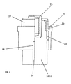
- FIG. 2 can recognize a terminal pole 12 and 13 respectively. This is cast from a lead material. Cast into the lead material is a threaded sleeve 15 made of a non-ferrous metal. This threaded sleeve 15 serves to receive a connecting screw for electrical contacting of the connection pole 12 or 13 with a connection 14 provided by a current-carrying cable.
- the terminal pole 12 or 13 carries a cap 17 placed on it.
- This cap is made of a plastic material, preferably polypropylene.
- the cap 17 is non-rotatably arranged on the pole 12 or 13, which is achieved in that the pole 12 or 13 has a radially extending projection 16 which is formed in the embodiment shown in the manner of a sword. This projection 16 engages positively in a provided by the cap 17 slot 18 a.
- FIG. 3 lets the configuration of the projection 16 in detail recognize.
- FIGS. 4 to 6 show the cap 17 in detail.
- the cap 17 has a first part 24 and a second part 25.
- the second part 25 is in the final assembled state at the head side of the associated terminal pole 12 and 13 at. It provides an opening 19 through which a terminal screw for insertion into the threaded sleeve 15 is to be guided.
- the first part 24 of the cap 17 provides peripherally a circumferential support web 20 ready.
- the housing cover 5 lies with its inside on the support surface 21 provided by the support web 20.
- the cap 17 receives in the final assembled state, an annular sealing element 22, as can be seen in particular from the illustration FIG. 5 results.
- the sealing element 22 lies inside the cap 17 in a positionally secure manner against a circumferential shoulder 23.
- the sealing element 22 is in detail in the FIGS. 7 and 8 shown. This is preferably made of plastic, namely of a thermoplastic elastomer.
- FIG. 9 lets recognize a mounting situation.
- the cap 17 is slipped over the terminal pole 12 and 13, respectively. It lies with its second part 25 on the head side at the connection pole 12 and 13 positionally secure and the threaded sleeve 15 passes through the second part 25 of the cap 17 provided opening 19.
- the preferably integrally formed with the terminal pole 12 and 13 projection 16 engages in the second part 25 of the cap 17 provided slot 18, whereby the cap 17 against rotation against the terminal pole 12 and 13 abuts.
- the sealing element 22 received by the first part 24 of the cap 17 rests against the terminal pole 12 or 13, whereby a fluid-tight termination is provided.
- first part 24 and the second part 25 of the cap 17 form a one-piece component.
- first part 24 and the second part 25 of the cap 17 are each formed as separate components and axially spaced from each other with the interposition of an elastically formed connecting bridge are coupled together.
- Such an embodiment provides the advantage that the upper, second part 25 of the cap 17 emigrate in the cap height direction, that is, can move relative to the first part 24 or to the housing cover 5. This allows, while avoiding whitening, a growth of the positive connection pole 12 that can not be avoided in the intended use case.
Abstract
Die Erfindung betrifft eine Batteriezelle für eine Batterie, insbesondere Traktionsbatterie, mit einem einseitig offenen Gehäusekasten (4) und einem die offene Gehäusekastenseite fluiddicht verschließenden Gehäusedeckel (5) sowie mit einem im Gehäusekasten (4) angeordneten Elektrodenplattenpaket (3), das einen Anschlusspol (12, 13) aufweist, der eine von dem Gehäusedeckel (5) bereitgestellte Öffnung (26) durchgreift. Um eine Batteriezelle bereitzustellen, die konstruktionsbedingt eine verbesserte Dichtwirkung zwischen Gehäusedeckel und Anschlusspolen bereitstellt, wird mit der Erfindung eine Batteriezelle der eingangs genannten Art vorgeschlagen, die sich dadurch auszeichnet, dass der Anschlusspol eine Kappe trägt, die polseitig ein Dichtelement bereitstellt und die gehäusedeckelseitig mit dem Gehäusedeckel verschweißt ist.

Description
Die Erfindung betrifft eine Batteriezelle für eine Batterie, insbesondere eine Traktionsbatterie, mit einem einseitig offenen Gehäusekasten und einem die offene Gehäusekastenseite fluiddicht verschließenden Gehäusedeckel sowie mit einem im Gehäusekasten angeordneten Elektrodenplattenpaket, das einen Anschlusspol aufweist, der eine von dem Gehäusedeckel bereitgestellte Öffnung durchgreift.The invention relates to a battery cell for a battery, in particular a traction battery, with a housing housing open on one side and a housing cover fluid-tightly closing the open housing case and with an arranged in the housing box electrode plate package having a terminal pole which engages through an opening provided by the housing cover.
Batteriezellen der vorbeschriebenen Art einerseits sowie Traktionsbatterien, die über eine Mehrzahl von miteinander elektrisch verschalteten Batteriezellen verfügen andererseits sind aus dem Stand der Technik an sich gut bekannt, weshalb es eines gesonderten druckschriftlichen Nachweises an dieser Stelle nicht bedarf.Battery cells of the type described above on the one hand and traction batteries, which have a plurality of electrically interconnected battery cells on the other hand, are well known in the prior art, which is why it does not require a separate documentary proof at this point.
Als nicht stationäre Batterien finden Traktionsbatterien typischerweise in der Fahrzeugtechnik Verwendung, beispielsweise bei Gabelstaplern, Hubwagen und/oder dergleichen. Vorbekannte Traktionsbatterien verfügen über eine Mehrzahl von miteinander elektrisch verschalteten Batteriezellen. Es kommen typischerweise je nach gewünschter Ausgangsspannung 12 Zellen (für 24 Volt), 24 Zellen (für 48 Volt) oder 40 Zellen (für 80 Volt) zum Einsatz.As non-stationary batteries, traction batteries typically find use in vehicle technology, for example in forklifts, pallet trucks and / or the like. Previously known traction batteries have a plurality of electrically interconnected battery cells. It typically comes down to the one you want
Dabei verfügt jede Batteriezelle über ein einen Gehäusekasten bereitstellendes Zellengehäuse, welcher Gehäusekasten einerseits einen Elektrolyten sowie andererseits einander abwechselnd positive und negative Elektrodenplatten aufnimmt, welche Elektrodenplatten zusammen ein Elektrodenplattenpaket bilden. Im endmontierten Zustand ist die offene Gehäusekastenseite des Zellengehäuses elekrolytdicht mittels eines Gehäusedeckels verschlossen.In this case, each battery cell has a cell housing providing a housing housing, which housing box on the one hand receives an electrolyte and on the other alternately positive and negative electrode plates, which electrode plates together form an electrode plate package. In the final assembled state, the open housing box side of the cell housing is sealed off by means of a housing cover.
Für eine elektrische Verschaltung und/oder Kontaktierung der Batteriezelle dienen Anschlusspole, die vom Elektrodenplattenpaket ausgehen und durch vom Gehäusedeckel bereitgestellte Öffnungen hindurchgeführt sind. Dabei sind die Öffnungen für eine elektrolytdichte Poldurchführung mit einer weichelastischen Dichtmanschette ausgerüstet, die sich im endmontierten Zustand an den jeweiligen Anschlusspol außenseitig anlegt. Es findet mithin eine Abdichtung zwischen Gehäusedeckel einerseits und Anschlusspolen andererseits aufgrund von Dichtmanschetten statt, wobei je Anschlusspol eine Dichtmanschette vorgesehen ist.For an electrical connection and / or contacting the battery cell are used connecting poles, which emanate from the electrode plate package and are passed through openings provided by the housing cover. The openings for an electrolyte-tight terminal bushing are equipped with a soft-elastic sealing collar, which rests on the outside in the final assembled state to the respective terminal pole. It therefore takes place a seal between the housing cover on the one hand and terminal poles on the other hand due to sealing sleeves, with each pole a sealing sleeve is provided.
Obgleich sich die vorbeschriebene Konstruktion im alltäglichen Praxiseinsatz bewährt hat, ist sie nicht frei von Nachteilen, und so ist insbesondere die Dichtwirkung zwischen einer Dichtmanschette einerseits und dem zugehörigen Anschlusspol andererseits nicht dauerhaft zufriedenstellend. Dies ist dadurch bedingt, dass die geometrischen Abmessungen der Einzelbauteile, insbesondere der Anschlusspole, des Gehäusedeckels und der davon bereitgestellten Poldurchtrittsöffnungen fertigungsbedingt toleranzbehaftet sind und deshalb variieren können. So ist der Abstand zwischen den vom Elektrodenplattenpaket bereitgestellten Anschlusspolen zwar vorgegeben, variiert aber zum Teil um einige Millimeter, was dazu führen kann, dass im endmontierten Zustand Teilabschnitte der Anschlusspole etwas fester an die sie jeweils umgebende Dichtmanschette gedrückt werden, wohingegen andere Polabschnitte etwas weniger fest an die jeweils zugehörige Dichtmanschette gepresst werden, so dass unterschiedliche Dichtwirkungen mit Bezug auf den Umfangsdurchmesser eines Anschlusspols Zustandekommen. Hinzu kommt, dass die Anschlusspole auch im Sinne windschiefer Geraden versetzt zueinander ausgerichtet sein können, was ebenfalls zu einem ungleichmäßigen Anliegen der jeweiligen Dichtmanschette am zugehörigen Anschlusspol führen kann. Auch hierdurch bedingt können ungewollte Undichtigkeiten bereits nach Ablauf einer nur kurzen Nutzungsdauer der Batteriezelle eintreten.Although the above-described construction has proven itself in everyday practical use, it is not free of disadvantages, and so in particular the sealing effect between a sealing sleeve on the one hand and the associated terminal pole on the other hand is not permanently satisfactory. This is due to the fact that the geometric dimensions of the individual components, in particular the terminal poles, the housing cover and the pole through openings provided therefrom are subject to tolerances due to production and therefore may vary. Thus, the distance between the provided by the electrode plate package terminal poles is indeed given, but varies in part by a few millimeters, which may cause that in the final assembled state portions of the terminal poles are pressed a little harder to each surrounding sealing sleeve, whereas other pole sections slightly less firm be pressed against the respectively associated sealing collar, so that different sealing effects with respect to the circumferential diameter of a terminal come about. In addition, the connecting poles can also be offset in the sense of wind-slippery straight lines, which also leads to one another uneven concerns the respective sealing sleeve at the associated terminal pole can lead. As a result of this, unwanted leaks can occur even after expiry of only a short useful life of the battery cell.
Ein Weiteres gilt es in diesem Zusammenhang zu berücksichtigen. Als Elektrolyt findet typischerweise Schwefelsäure Verwendung, insbesondere bei Bleiakkumulatoren. Dabei besteht die besondere Schwierigkeit darin, dass Schwefelsäure vergleichsweise hohe Kapillarwirkungen mit sich bringt, so dass der Elektrolyt mit der Zeit auch kleinste Ritzen und Spalten durchwandert. Etwaige Ungenauigkeiten im Anliegen der Dichtmanschette am zugehörigen Anschlusspol wirken sich deshalb entsprechend undichtigkeitsverschärfend aus.Another thing to consider in this context. Sulfuric acid is typically used as the electrolyte, in particular for lead-acid batteries. The particular difficulty is that sulfuric acid brings comparatively high capillary effects, so that the electrolyte with time passes through even the smallest cracks and gaps. Any inaccuracies in the concern of the sealing sleeve at the associated connection pole therefore have a correspondingly unsightly effect.
Es ist ausgehend vom Vorgeschriebenen die Aufgabe der Erfindung, eine Batteriezelle bereitzustellen, die konstruktionsbedingt eine verbesserte Dichtwirkung zwischen Gehäusedeckel und Anschlusspolen bereitstellt.It is based on the prescribed, the task of the invention to provide a battery cell, the design provides an improved sealing effect between the housing cover and terminal poles.
Zur Lösung dieser Aufgabe wird mit der Erfindung eine Batteriezelle der eingangs genannten Art vorgeschlagen, die sich dadurch auszeichnet, dass der Anschlusspol eine Kappe trägt, die polseitig ein Dichtelement bereitstellt und die gehäusedeckelseitig mit dem Gehäusedeckel verschweißt ist.To solve this problem, a battery cell of the type mentioned is proposed with the invention, which is characterized in that the terminal pole carries a cap, the pole side provides a sealing element and the housing cover side is welded to the housing cover.
Nach der erfindungsgemäßen Konstruktion kommt eine Kappe zum Einsatz, und zwar je Anschlusspol eine Kappe. Im endmontierten Zustand ist der Anschlusspol unter Zwischenordnung der zugehörigen Kappe durch die jeweilige vom Gehäusedeckel bereitgestellte Öffnung hindurchgeführt. Dabei übernimmt die Kappe zwei Funktionen. Zum einen stellt sie ein Dichtelement bereit, und zwar polseitig. Zwischen Kappe einerseits und Anschlusspol andererseits ist mithin ein Dichtelement angeordnet, das für ein elektrolytdichtes Anliegen des Anschlusspols an der Innenoberfläche der Kappe sorgt. Zum anderen ist die Kappe gehäuseseitig mit dem Gehäusedeckel verschweißt, das heißt stoffschlüssig verbunden, mithin elektrolytdicht an den Gehäusedeckel angeschlossen.According to the construction according to the invention, a cap is used, namely a terminal cap. In the final assembled state of the terminal pole is passed through the respective opening provided by the housing cover with the interposition of the associated cap. The cap takes on two functions. First, it provides a sealing element, namely pole side. Between cap on the one hand and terminal pole on the other hand, a sealing element is thus arranged, which ensures an electrolyte-tight concern of the terminal pole on the inner surface of the cap. On the other hand, the cap is welded on the housing side to the housing cover, that is cohesively connected, thus connected electrolyte-tight to the housing cover.
Der besondere Vorteil der erfindungsgemäßen Ausgestaltung liegt darin, dass die als Hilfselement dienende Kappe etwaige Fertigungstoleranzen in Relation zum Gehäusedeckel ausgleicht, wobei dieser Ausgleich im Unterschied zum vorerläuterten Stand der Technik nicht die Position des Dichtelements betrifft, sondern allein die relative Lage der Kappe zum Gehäusedeckel. Nach einer erfolgten Ausrichtung steht die Kappe quasi kraft- beziehungsweise spannungsfrei zum Gehäusedeckel und es kann eine Verschweißung von Kappe und Gehäusedeckel stattfinden. Im Unterschied zum Stand der Technik werden also etwaige Lagetoleranzen durch eine verändert zu setzende Schweißnaht korrigiert, und nicht etwa dadurch, dass sich die relative Lage des Dichtelements zum jeweiligen Anschlusspol verändert.The particular advantage of the embodiment according to the invention is that the serving as an auxiliary cap compensates for possible manufacturing tolerances in relation to the housing cover, this compensation in contrast to vorerläuterten The prior art does not concern the position of the sealing element, but only the relative position of the cap to the housing cover. After a successful alignment, the cap is quasi force- or stress-free to the housing cover and there may be a welding of cap and housing cover. In contrast to the prior art, therefore, any positional tolerances are corrected by a weld seam to be set differently, and not by the fact that the relative position of the sealing element to the respective terminal pole changes.
Im Ergebnis der erfindungsgemäßen Ausgestaltung ergibt sich eine dauerhaft zuverlässige Abdichtung zwischen dem Dichtelement und dem Pol, das heißt der das Dichtelement tragenden Kappe und dem Anschlusspol einerseits sowie der Kappe und dem Gehäusedeckel andererseits, wobei die Dichtigkeit zwischen Kappe und Gehäusedeckel durch die Verschweißung erzeugt ist.As a result of the embodiment of the invention results in a permanently reliable seal between the sealing element and the pole, that is the cap carrying the sealing element and the terminal pole on the one hand and the cap and the housing cover on the other hand, wherein the tightness between the cap and the housing cover is produced by the welding.
Die vorbeschriebene Konstruktion der Anschlusspolabdichtung erbringt zudem den Vorteil, dass die Anschlusspole nach dem sogenannten COS-Verfahren (Cast on Strip-Verfahren) hergestellt werden können. Gemäß diesem Verfahren wird in eine Gießform flüssiges Blei eingegeben, wobei die Gießform sowohl den Pol als auch die den Pol tragende Brücke im Negativen wiedergibt. Vorkonfektionierte Elektroden werden mit ihren Fahnen voran in das flüssige Blei der Gießform getaucht und es wird die Aushärtung des Bleimaterials abgewartet. Im Ergebnis dieser Verfahrensdurchführung steht eine einstückig mit den Fahnen der Elektroden ausgebildete Baukomponente, die sowohl die die Fahnen der einzelnen Elektroden miteinander verbindende Brücke als auch den einstückig an der Brücke angeordneten Pol bereitstellt. Die so vorbereiteten Elektroden können dann samt daran ausgebildetem Pol in den Gehäusekasten des Gehäuses eingebracht werden.The above-described construction of the terminal pole seal also affords the advantage that the terminal poles can be produced by the so-called COS method (cast on strip method). According to this method, liquid lead is introduced into a mold, the mold representing both the pole and the bridge carrying the pole in the negative. Pre-assembled electrodes are dipped with their flags ahead in the liquid lead of the mold and it is waiting for the hardening of the lead material. As a result of this process implementation stands a component formed integrally with the lugs of the electrodes, which provides both the bridge connecting the lugs of the individual electrodes and the pole arranged integrally on the bridge. The electrodes prepared in this way can then be introduced, together with the pole formed thereon, into the housing box of the housing.
Die Herstellung nach dem COS-Verfahren ist in vorteilhafter Weise einfach in der Handhabung und zudem preisgünstig. Die mit der Erfindung vorgeschlagene Polabdichtung lässt sich in vorteilhafter Weise mit nach dem COS-Verfahren vorbereiteten Elektroden kombinieren, so dass sich insoweit ein synergetischer Effekt ergibt, da die erfindungsgemäße Ausgestaltung nicht nur eine verbesserte Polabdichtung bereitstellt, sie ermöglicht zudem eine einfache und preisgünstige Herstellung.The preparation by the COS process is advantageously easy to handle and also inexpensive. The pole seal proposed by the invention can advantageously be combined with electrodes prepared by the COS method, so that a synergistic effect results insofar as the embodiment according to the invention not only provides an improved pole seal, but also enables simple and inexpensive production.
Gemäß einer bevorzugten Ausführungsform der Erfindung ist vorgesehen, dass die Kappe außenumfangsseitig einen umlaufenden Stützsteg aufweist, auf dem der Gehäusedeckel aufliegt. Mit dem Stützsteg untergreift die Kappe die Randkante der zur Poldurchführung im Gehäusedeckel vorgesehenen Öffnung. Es findet mithin eine Abstützung des Gehäusedeckels statt. Dabei liegt der Stützsteg mit seiner gehäusedeckelseitig ausgebildeten Stirnfläche bevorzugterweise am Gehäusedeckel an. Zum einen wird hierdurch eine zusätzliche Stabilisierung von Kappe und Gehäusedeckel erreicht, zum anderen können so verbessert etwaige Lagetoleranzen zwischen Kappe und Gehäusedeckelöffnung ausgeglichen werden, denn ein Verschweißen findet bevorzugterweise deckelunterseitig zwischen Stützsteg und Gehäusedeckel statt.According to a preferred embodiment of the invention it is provided that the cap has on the outer peripheral side a circumferential support web on which the housing cover rests. With the support bar, the cap engages under the edge of the opening provided for the pole bushing in the housing cover. There is therefore a support of the housing cover instead. In this case, the support web with its housing cover side formed end face is preferably on the housing cover. On the one hand this additional stabilization of the cap and housing cover is achieved, on the other hand, so any positional tolerances between the cap and housing cover opening can be compensated, because welding preferably takes place on the cover side between support web and housing cover instead.
Die Kappe und das Dichtelement sind bevorzugterweise als einstückiges Bauteil ausgebildet. Dies vereinfacht die Herstellung, insbesondere Montage der erfindungsgemäßen Batteriezelle.The cap and the sealing element are preferably formed as a one-piece component. This simplifies the production, in particular assembly of the battery cell according to the invention.
Die Kappe besteht aus Kunststoff, vorzugsweise aus Polypropylen. Auch der Gehäusedeckel der Batteriezelle besteht aus Polypropylen, was ein Verschweißen der Kappe mit dem Gehäusedeckel vereinfacht.The cap is made of plastic, preferably polypropylene. The housing cover of the battery cell is made of polypropylene, which simplifies welding of the cap to the housing cover.
Als Dichtelement kann ein O-Ring oder eine Dichtmanschette zum Einsatz kommen. Diese besteht aus Kunststoff, vorzugsweise einem thermoplastischen Elastomer, was besonders gute Dichteigenschaften mit sich bringt.As a sealing element, an O-ring or a sealing sleeve can be used. This consists of plastic, preferably a thermoplastic elastomer, which brings particularly good sealing properties with it.
Zur Bereitstellung eines einstückigen Bauteils kann das Dichtelement in die Kappe eingespritzt oder in diese eingeklebt sein.To provide a one-piece component, the sealing element can be injected into the cap or glued into it.
Gemäß einem weiteren Merkmal der Erfindung ist vorgesehen, dass die Kappe zweiteilig ausgebildet ist und einen mit dem Gehäusedeckel verschweißten ersten Teil sowie einen vom ersten Teil axial beabstandeten zweiten Teil aufweist, wobei zwischen dem ersten und dem zweiten Teil eine elastisch ausgebildete Verbindungsbrücke ausgebildet ist. Gemäß dieser Konstruktion ist es dem zweiten Teil der Kappe gestattet, in Axialrichtung, das heißt in Höhenrichtung der Kappe eine Relativbewegung zum ersten Teil der Kappe, das heißt dem mit dem Gehäusedeckel verschweißten Teil der Kappe zu vollführen. Diese relative Beweglichkeit des zweiten Teils der Kappe ermöglicht in vorteilhafter Weise einen Längenausgleich, was hilft, sogenannten Weißbruch am Gehäusedeckel zu vermeiden.According to a further feature of the invention, it is provided that the cap is formed in two parts and has a welded to the housing cover first part and an axially spaced from the first part second part, wherein between the first and the second part an elastically formed connecting bridge is formed. According to this construction, the second part of the cap is allowed to perform in the axial direction, that is, in the height direction of the cap, a relative movement to the first part of the cap, that is, the part of the cap welded to the housing cover. These Relative mobility of the second part of the cap advantageously allows a length compensation, which helps to avoid so-called white fracture on the housing cover.
Im Laufe der Lebensdauer einer Batterie kann es durch interkristalline Korrosion zu einem Wachsen der positiven Platten in Höhenrichtung kommen. Infolge dessen drückt der Anschlusspol der positiven Platten von unten gegen den Gehäusedeckel. Dies kann zum sogenannten Weißbruch führen, bei dem es sich um mikroskopisch kleine Bereiche handelt, deren Begrenzungsflächen mit einzelnen extrem verstreckten Materialstrengen überbrückt sind und die durch eine milchig weiße Verfärbung erkennbar werden. Weißbruch ist insofern eine Vorschädigung des Materials und kann der Beginn eines vollständigen Materialbruches sein. Um hier gegenzuwirken, wird mit der Erfindung die zweiteilige Ausgestaltung der Kappe vorgeschlagen. Dabei sind die beiden Teile der Kappe über eine elastisch ausgebildete Verbindungsbrücke miteinander gekoppelt. Diese elastische Verbindungsbrücke ermöglicht im Betriebsfall einen Höhenausgleich in Vertikalausrichtung, womit der Pol der positiven Platten unter Vermeidung von Weißbruch auswandern kann.Over the life of a battery, intercrystalline corrosion can cause the positive plates to grow in the vertical direction. As a result, pushes the terminal pole of the positive plates from below against the housing cover. This can lead to the so-called white fracture, which is microscopically small areas whose boundary surfaces are bridged with individual extremely stretched material strictures and which are recognizable by a milky white discoloration. White fracture is therefore a pre-damage to the material and can be the beginning of a complete material break. To counteract here, the invention proposes the two-part embodiment of the cap. The two parts of the cap are coupled together via an elastically formed connecting bridge. This elastic connecting bridge allows in case of operation, a height compensation in vertical orientation, whereby the pole of the positive plates can emigrate while avoiding white fracture.
Gemäß einem weiteren Merkmal der Erfindung ist vorgesehen, dass die Kappe verdrehfest am Anschlusspol angeordnet ist. Dies schützt den Anschlusspol vor einem etwaigen Brückenabriss, insbesondere bei der Ausbildung einer entsprechenden Verschraubung zur Anschlusskabelkontaktierung.According to a further feature of the invention it is provided that the cap is arranged rotationally fixed to the terminal pole. This protects the terminal pole from any bridging, in particular in the formation of a corresponding screw for connecting cable contacting.
Typischerweise ist zur Kontaktierung eines Anschlusskabels am jeweils zugehörigen Pol vorgesehen, dieses Anschlusskabel mit dem Pol zu verschrauben. Diese Verschraubung erfolgt unter Anlegen eines Drehmoments von zum Beispiel 20 Nm. Das Widerlager für die Schraube bildet der Pol beziehungsweise eine vom Pol aufgenommene Gewindehülse aus einem Buntmaterial. Der Pol stützt sich seinerseits an der Brücke und damit an den zugehörigen Elektrodenplatten ab, wobei die Verbindung der Elektrodenplatten mit der Brücke lediglich über die jeweiligen Fahnen erfolgt, welche eine besondere Schwachstelle darstellen. Bei einer ordnungsgemäßen Befestigung eines Anschlusskabels mittels der zugehörigen Schraube am Pol kann es insbesondere bei vergleichsweise schmalen Batterien, das heißt solchen, die nur über wenige Elektrodenplatten verfügen, dazu kommen, dass sich die mit der Brücke verbundenen Fahnen der einzelnen Elektrodenplatten im Moment der Drehmomenteinleitung verbiegen oder sogar abreißen. Um diesem Problem zu begegnen, ist mit der Erfindung vorgeschlagen, die Kappe verdrehfest am Pol anzuordnen. Diese verdrehfeste Anordnung sorgt dafür, dass bei einem Eindrehen einer Verbindungsschraube zum Anschluss eines Anschlusskabels das eingeleitete Drehmoment über den verdrehfesten Kontakt von Kappe und Pol in die Kappe und von dort aus über die Verschweißung in den Gehäusedeckel eingeleitet wird. Damit ist die Gefahr von unter Umständen abreißenden Fahnen und/oder Brücken überwunden.Typically, it is provided for contacting a connecting cable to the respectively associated pole to screw this connecting cable to the pole. This screwing is done by applying a torque of, for example 20 Nm. The abutment for the screw forms the Pol or a recorded from the pole threaded sleeve made of a color material. The pole in turn is supported on the bridge and thus on the associated electrode plates, wherein the connection of the electrode plates with the bridge takes place only via the respective flags, which represent a particular weak point. With a proper attachment of a connection cable by means of the associated screw on the pole, it can happen, in particular with comparatively narrow batteries, ie those which have only a few electrode plates, that the lugs of the individual electrode plates connected to the bridge bend at the moment of torque introduction or even demolish. To counteract this problem, it is proposed with the invention to arrange the cap against rotation on the pole. This rotationally fixed arrangement ensures that, when screwing in a connecting screw for connecting a connecting cable, the introduced torque is introduced via the rotationally fixed contact of cap and pole in the cap and from there via the welding in the housing cover. This overcomes the danger of possibly breaking flags and / or bridges.
Die verdrehfeste Verbindung von Kappe und Pol kann beispielsweise dadurch ausgebildet werden, dass die Kappe einen in Kappenhöhenrichtung verlaufenden Schlitz aufweist, in den ein schwertähnlich ausgebildeter Vorsprung des Pols eingreift. Es wird so eine formschlüssige Verbindung zwischen Kappe einerseits und Pol andererseits ausgebildet, die in der Lage ist, Drehmomente zu übertragen, so dass ein Ableiten in de Gehäusedeckel beziehungsweise den damit verschweißten Gehäusekasten erfolgen kann. Dabei hat die Ausbildung eines schwertähnlichen Vorsprungs am Pol zudem den Vorteil, dass dieser auch im Rahmen des schon vorbeschriebenen COS-Verfahrens ausgebildet werden kann.The non-rotatable connection of cap and pole can be formed, for example, by the cap having a slot extending in the cap height direction into which a sword-like projection of the pole engages. It is thus formed a positive connection between the cap on the one hand and pole on the other hand, which is able to transmit torques, so that a derivation in de housing cover or the thus welded housing box can be done. In this case, the formation of a sword-like projection on the pole also has the advantage that it can also be formed in the context of the previously described COS method.
Mit der Erfindung wird insgesamt eine Konstruktion vorgeschlagen, die eine gegenüber dem Stand der Technik deutlich verbesserte Polabdichtung ermöglicht, und dies bei gleichzeitiger Verwendung des COS-Verfahrens zur Polherstellung, wodurch der Einsatz eines einfach durchzuführenden und preisgünstigen Herstellungsverfahrens gestattet ist.The invention as a whole proposes a construction which enables a much improved over the prior art pole seal, while using the COS method for Polherstellung, whereby the use of an easy to perform and inexpensive manufacturing process is allowed.
Weitere Merkmale und Vorteile der Erfindung ergeben sich aus der nachfolgenden Beschreibung anhand der Figuren. Dabei zeigen:
Figur 1- in schematischer Schnittdarstellung eine Batteriezelle nach der Erfindung;
- Figur 2
- in einer teilgeschnittenen Seitenansicht einen mit einer Kappe ausgerüsteten Anschlusspol;
- Figur 3
- in schematischer Seitenansicht den Anschlusspol nach
Figur 2 ; - Figur 4
- in einer schematischen Seitenansicht die Kappe nach
Figur 2 ; Figur 5- in geschnittener Seitenansicht die Kappe nach
Figur 4 gemäß Schnittlinie V-V; - Figur 6
- in schematischer Seitenansicht die Kappe nach
Figur 4 , und zwar im Unterschied zuFigur 4 um 90° gedreht; - Figur 7
- in einer schematischen Seitenansicht ein Dichtelement;
- Figur 8
- in geschnittener Seitenansicht das Dichtelement nach
Figur 7 gemäß Schnittlinie VIII - VIII und - Figur 9
- in einer schematisch perspektivischen Detailansicht eine Einbausituation.
- FIG. 1
- in a schematic sectional view of a battery cell according to the invention;
- FIG. 2
- in a partially sectioned side view of a cap equipped terminal pole;
- FIG. 3
- in a schematic side view of the terminal after
FIG. 2 ; - FIG. 4
- in a schematic side view of the cap
FIG. 2 ; - FIG. 5
- in cut side view of the cap
FIG. 4 according to section line VV; - FIG. 6
- in a schematic side view of the cap
FIG. 4 , unlikeFIG. 4 turned by 90 degrees; - FIG. 7
- in a schematic side view of a sealing element;
- FIG. 8
- in a sectional side view of the sealing element after
FIG. 7 according to section line VIII - VIII and - FIG. 9
- in a schematic perspective detail view of a mounting situation.
Die Batteriezelle 1 verfügt über ein Gehäuse 2. Dieses weist einen Gehäusekasten 4 einerseits und einen den Gehäusekasten 4 im endmontierten Zustand fluiddicht verschließenden Gehäusedeckel 5 auf. Der Gehäsuekasten 4 und der Gehäusedeckel 5 sind bevorzugterweise miteinander verschweißt.The
Innerhalb des Gehäuses 2 ist ein Elektrodenplattenpaket 3 angeordnet. Dieses besteht aus einander abwechselnd angeordneten positiven Elektrodenplatten 6 einerseits und negativen Elektrodenplatten 7 andererseits. Die Elektrodenplatten 6 bzw. 7 verfügen deckelseitig über Anschlussfahnen, wobei die positiven Elektrodenplatten 6 die Fahnen 8 und die negativen Elektrodenplatten 7 die Fahnen 9 bereitstellen. Mittels einer jeweils gemeinsamen Brücke 10 beziehungsweise 11 sind die Fahnen 8 beziehungsweise 9 elektrisch miteinander gekoppelt. Jede Brücke 10 beziehungsweise 11 trägt einen Anschlusspol 12 beziehungsweise 13, wobei die Brücke 11 der negativen Elektrodenplatten 7 den negativen Anschlusspol 12 und die Brücke 10 der positiven Elektrodenplatten 6 den positiven Anschlusspol 13 tragen.Within the housing 2, an electrode plate package 3 is arranged. This consists of alternately arranged positive electrode plates 6 on the one hand and negative electrode plates 7 on the other. The electrode plates 6 and 7 have cover lugs on terminal lugs, wherein the positive electrode plates 6, the flags 8 and the negative electrode plates 7, the flags 9 provide. By means of a respective
Die Anschlusspole 12 und 13 durchgreifen entsprechende Öffnungen 26 im Gehäusedeckel 5, so dass sie für eine Anschlusskontaktierung von außerhalb des Gehäuses 2 zugänglich sind. Im gezeigten Ausführungsbeispiel sind Anschlüsse 14 einer nicht näher dargestellten Verkabelung mit den Anschlusspolen 12 beziehungsweise 13 jeweils verschraubt, zu welchem Zweck die Anschlusspole 12 und 13 in
Für einen fluiddichten Poldurchgriff trägt der Anschlusspol 12 beziehungsweise 13 erfindungsgemäß eine Kappe 17, die polseitig ein Dichtelement 22 bereitstellt und die gehäusedeckelseitig mit dem Gehäusedeckel 5 verschweißt ist, welcher Sachzusammenhang sich aus einer Zusammenschau der
Der Anschlusspol 12 beziehungsweise 13 trägt eine auf ihn aufgesetzte Kappe 17. Diese Kappe besteht aus einem Kunststoffmaterial, vorzugsweise Polypropylen. Die Kappe 17 ist verdrehfest am Pol 12 beziehungsweise 13 angeordnet, was dadurch erreicht ist, dass der Pol 12 beziehungsweise 13 einen sich radial erstreckenden Vorsprung 16 aufweist, der im gezeigten Ausführungsbeispiel nach Art eines Schwerts ausgebildet ist. Dieser Vorsprung 16 greift formschlüssig in einen von der Kappe 17 bereitgestellten Schlitz 18 ein.The
Die
Der erste Teil 24 der Kappe 17 stellt umfangsseitig einen umlaufenden Stützsteg 20 bereit. Im endmontierten Zustand liegt der Gehäusedeckel 5 mit seiner Innenseite auf der vom Stützsteg 20 bereitgestellten Stützfläche 21 auf.The
Die Kappe 17 nimmt im endmontierten Zustand ein ringförmiges Dichtelement 22 auf, wie sich dies insbesondere aus der Darstellung nach
Das Dichtelement 22 ist im Detail in den
Das vom ersten Teil 24 der Kappe 17 aufgenommene Dichtelement 22 liegt am Anschlusspol 12 beziehungsweise 13 an, womit ein fluiddichter Abschluss gegeben ist.The sealing
Der außenumfangsseitig vom zweiten Teil 25 der Kappe 17 bereitgestellte Stützsteg 20 liegt an einem innenseitig des Gehäusedeckels 5 ausgebildeten Kragen 27 an, wobei der Stützsteg 20 mit dem Kragen 27 fluiddicht verbunden, vorzugsweise verschweißt ist.The outer peripheral side provided by the
Aufgrund des zwischen dem Anschlusspol 12 beziehungsweise 13 und der Kappe 17 angeordneten Dichtelements 22 einerseits und der Verschweißung des Stützstegs 20 der Kappe 17 mit dem Kragen 27 des Gehäusedeckels 5 andererseits ist eine insgesamt fluid-und damit elektrolytdichte Durchführung des Pols 12 beziehungsweise 13 durch die zugehörige Öffnung 26 im Gehäusedeckel 5 erreicht.Due to the between the terminal 12 and 13 and the
Im gezeigten Ausführungsbeispiel bilden der erste Teil 24 und der zweite Teil 25 der Kappe 17 ein einstückiges Bauteil aus. Alternativ zu dieser Ausgestaltung kann vorgesehen sein, dass der erste Teil 24 und der zweite Teil 25 der Kappe 17 jeweils als separate Bauteile ausgebildet sind und axial voneinander beabstandet unter Zwischenordnung einer elastisch ausgebildeten Verbindungsbrücke miteinander gekoppelt sind. Eine solche Ausgestaltung erbringt den Vorteil, dass der obere, zweite Teil 25 der Kappe 17 in Kappenhöhenrichtung auswandern, das heißt sich relativ zum ersten Teil 24 beziehungsweise zum Gehäusedeckel 5 bewegen kann. Dies lässt unter Vermeidung von Weißbruch ein im bestimmungsgemäßen Verwendungsfall nicht zu vermeidendes Wachsen des positiven Anschlusspols 12 zu.In the embodiment shown, the
Von besonderem Vorteil der erfindungsgemäßen Ausgestaltung ist, dass etwaige geometrische Toleranzen in der relativen Ausrichtung von Anschlusspolen einerseits und Gehäusedeckel 5 beziehungsweise den davon bereitgestellten Öffnungen 26 andererseits nicht vom Dichtelement 22, sondern durch die Lage der Kappe 17 kompensiert werden. Damit ist eine dauerhaft zuverlässige Abdichtung des Anschlusspols 12 beziehungsweise 13 gegenüber der Kappe 17 mittels des Dichtelements 22 sichergestellt.
Claims (11)
Priority Applications (5)
| Application Number | Priority Date | Filing Date | Title |
|---|---|---|---|
| PL14177887T PL2978042T3 (en) | 2014-07-21 | 2014-07-21 | Battery cell for a battery, in particular traction battery |
| EP14177887.8A EP2978042B1 (en) | 2014-07-21 | 2014-07-21 | Battery cell for a battery, in particular traction battery |
| ES14177887.8T ES2593654T3 (en) | 2014-07-21 | 2014-07-21 | Battery element for a battery, in particular a traction battery |
| CN201510425560.6A CN105185926B (en) | 2014-07-21 | 2015-07-19 | Battery cell for battery pack, especially battery of electric vehicle group |
| US14/804,364 US9608241B2 (en) | 2014-07-21 | 2015-07-21 | Battery cell for a battery, especially for a traction battery |
Applications Claiming Priority (1)
| Application Number | Priority Date | Filing Date | Title |
|---|---|---|---|
| EP14177887.8A EP2978042B1 (en) | 2014-07-21 | 2014-07-21 | Battery cell for a battery, in particular traction battery |
Publications (2)
| Publication Number | Publication Date |
|---|---|
| EP2978042A1 true EP2978042A1 (en) | 2016-01-27 |
| EP2978042B1 EP2978042B1 (en) | 2016-06-29 |
Family
ID=51265488
Family Applications (1)
| Application Number | Title | Priority Date | Filing Date |
|---|---|---|---|
| EP14177887.8A Active EP2978042B1 (en) | 2014-07-21 | 2014-07-21 | Battery cell for a battery, in particular traction battery |
Country Status (5)
| Country | Link |
|---|---|
| US (1) | US9608241B2 (en) |
| EP (1) | EP2978042B1 (en) |
| CN (1) | CN105185926B (en) |
| ES (1) | ES2593654T3 (en) |
| PL (1) | PL2978042T3 (en) |
Families Citing this family (6)
| Publication number | Priority date | Publication date | Assignee | Title |
|---|---|---|---|---|
| FR3055741B1 (en) * | 2016-09-07 | 2018-09-21 | Commissariat A L'energie Atomique Et Aux Energies Alternatives | TRAVERSEE FORMING TERMINAL FOR ELECTROCHEMICAL ACCUMULATOR METAL-ION AND ACCUMULATOR ASSOCIATED |
| KR20190001367A (en) * | 2017-06-27 | 2019-01-04 | 주식회사 현대케피코 | Injector fixing structure of fuel rail |
| CN107394283B (en) * | 2017-07-24 | 2019-12-24 | 中国西电电气股份有限公司 | Compact liquid metal battery and assembling method thereof |
| US20230006318A1 (en) * | 2019-11-01 | 2023-01-05 | Cps Technology Holdings Llc | Battery terminal bushing & lead acid battery |
| US20230060460A1 (en) * | 2020-02-28 | 2023-03-02 | Panasonic Intellectual Property Management Co., Ltd. | Power storage device |
| CN114335859A (en) * | 2021-12-31 | 2022-04-12 | 歌尔光学科技有限公司 | Battery installation device and electronic product |
Citations (4)
| Publication number | Priority date | Publication date | Assignee | Title |
|---|---|---|---|---|
| DE2514508A1 (en) * | 1975-04-03 | 1976-10-21 | Varta Batterie | Accumulator cell terminal post seal - with sealing ring pressed on pole bridge collar by insulating sleeve |
| DE2833416B1 (en) * | 1978-07-29 | 1979-09-27 | Hoppecke Zoellner Sohn Accu | Process for the production of a pole bushing for accumulators and their design |
| WO1990005999A1 (en) * | 1988-11-24 | 1990-05-31 | Akkumulatorenfabrik Dr. Leopold Jungfer | Introduction of a lead terminal through the case cover of accumulator cells |
| US6312852B1 (en) * | 1998-02-26 | 2001-11-06 | C&D Charter Holdings Inc. | Battery cell cover with flexible positive post terminal |
Family Cites Families (3)
| Publication number | Priority date | Publication date | Assignee | Title |
|---|---|---|---|---|
| US3929932A (en) | 1973-03-26 | 1975-12-30 | Dart Ind Inc | High impact compositions of polyethylene and polypropylene block copolymers |
| CN202167550U (en) * | 2011-06-29 | 2012-03-14 | 比亚迪股份有限公司 | Battery cover component and battery |
| CN202339940U (en) * | 2011-11-16 | 2012-07-18 | 武汉长光电源有限公司 | Integrated sealing assembly of lead-acid storage battery pole for sealing |
-
2014
- 2014-07-21 PL PL14177887T patent/PL2978042T3/en unknown
- 2014-07-21 ES ES14177887.8T patent/ES2593654T3/en active Active
- 2014-07-21 EP EP14177887.8A patent/EP2978042B1/en active Active
-
2015
- 2015-07-19 CN CN201510425560.6A patent/CN105185926B/en active Active
- 2015-07-21 US US14/804,364 patent/US9608241B2/en active Active
Patent Citations (4)
| Publication number | Priority date | Publication date | Assignee | Title |
|---|---|---|---|---|
| DE2514508A1 (en) * | 1975-04-03 | 1976-10-21 | Varta Batterie | Accumulator cell terminal post seal - with sealing ring pressed on pole bridge collar by insulating sleeve |
| DE2833416B1 (en) * | 1978-07-29 | 1979-09-27 | Hoppecke Zoellner Sohn Accu | Process for the production of a pole bushing for accumulators and their design |
| WO1990005999A1 (en) * | 1988-11-24 | 1990-05-31 | Akkumulatorenfabrik Dr. Leopold Jungfer | Introduction of a lead terminal through the case cover of accumulator cells |
| US6312852B1 (en) * | 1998-02-26 | 2001-11-06 | C&D Charter Holdings Inc. | Battery cell cover with flexible positive post terminal |
Also Published As
| Publication number | Publication date |
|---|---|
| US20160020440A1 (en) | 2016-01-21 |
| PL2978042T3 (en) | 2017-01-31 |
| ES2593654T3 (en) | 2016-12-12 |
| CN105185926B (en) | 2017-10-03 |
| EP2978042B1 (en) | 2016-06-29 |
| CN105185926A (en) | 2015-12-23 |
| US9608241B2 (en) | 2017-03-28 |
Similar Documents
| Publication | Publication Date | Title |
|---|---|---|
| EP2978042B1 (en) | Battery cell for a battery, in particular traction battery | |
| EP3821478B1 (en) | Battery housing | |
| DE102011116559B4 (en) | Method for producing a spindle drive for an adjusting element of a motor vehicle | |
| EP2150989A1 (en) | Electric connection device for photovoltaic modules | |
| DE102007042589A1 (en) | Device for fuel-tight passage of electrical contact elements through a wall, and such contact element | |
| DE102014218676A1 (en) | Terminal for connecting battery terminals | |
| DE102008010814B4 (en) | Single cell for a battery and its use | |
| DE2206013A1 (en) | Electric battery for automobiles or the like | |
| DE102019109541A1 (en) | Method for producing a cover assembly for a cell housing of a prismatic battery cell with a sealing element and battery cell | |
| DE102005052309B4 (en) | Connecting bolt, connecting element and electrically conductive coupling device | |
| DE102015013472A1 (en) | Electrical contact unit for producing an electrical connection between a battery terminal and a vehicle electrical system of a vehicle | |
| DE102015011898A1 (en) | Energy storage device and cell holder for an energy storage device | |
| WO2014140221A1 (en) | Connection bush for a housing of an electrical component, particularly a storage battery | |
| DE102011014335A1 (en) | Cylinder head cover for an internal combustion engine | |
| DE3039682A1 (en) | ELECTRICAL COMPONENT | |
| EP2923392A1 (en) | Connection pole for an accumulator, pole shaft of an accumulator, and accumulator | |
| EP2416408B1 (en) | Lid section for an accumulator and accumulator with such a lid section | |
| DE102012007967A1 (en) | Cable lug for electrical connection of motor car to ground line, has captive and rotatable screw which is screwed in ground pin of motor vehicle | |
| DE3111551A1 (en) | CONNECTION TERMINAL ARRANGEMENT ON A BATTERY SIDE WALL AND METHOD FOR THE PRODUCTION THEREOF | |
| DE102008056133A1 (en) | Connector for an electrical connection between a conductor and e.g. conductive vehicle bodywork, has a section welded to the structure with welding projections outside the center zone | |
| DE102012202063A1 (en) | Pressure measuring device for a combustion chamber pressure sensor | |
| DE102009041604A1 (en) | electromagnet | |
| DE102014224215B4 (en) | Method for electrically connecting at least two battery cells, battery cell and transport container with several battery cells | |
| EP1319608B1 (en) | Container in particular for box pallet | |
| DE102022125074B3 (en) | CONTACT ELEMENT FOR ELECTRICALLY CONDUCTIVE CONTACTING A BATTERY CELL HOUSING |
Legal Events
| Date | Code | Title | Description |
|---|---|---|---|
| PUAI | Public reference made under article 153(3) epc to a published international application that has entered the european phase |
Free format text: ORIGINAL CODE: 0009012 |
|
| 17P | Request for examination filed |
Effective date: 20150727 |
|
| AK | Designated contracting states |
Kind code of ref document: A1 Designated state(s): AL AT BE BG CH CY CZ DE DK EE ES FI FR GB GR HR HU IE IS IT LI LT LU LV MC MK MT NL NO PL PT RO RS SE SI SK SM TR |
|
| AX | Request for extension of the european patent |
Extension state: BA ME |
|
| GRAP | Despatch of communication of intention to grant a patent |
Free format text: ORIGINAL CODE: EPIDOSNIGR1 |
|
| INTG | Intention to grant announced |
Effective date: 20160218 |
|
| GRAS | Grant fee paid |
Free format text: ORIGINAL CODE: EPIDOSNIGR3 |
|
| GRAA | (expected) grant |
Free format text: ORIGINAL CODE: 0009210 |
|
| AK | Designated contracting states |
Kind code of ref document: B1 Designated state(s): AL AT BE BG CH CY CZ DE DK EE ES FI FR GB GR HR HU IE IS IT LI LT LU LV MC MK MT NL NO PL PT RO RS SE SI SK SM TR |
|
| REG | Reference to a national code |
Ref country code: GB Ref legal event code: FG4D Free format text: NOT ENGLISH |
|
| REG | Reference to a national code |
Ref country code: CH Ref legal event code: EP |
|
| REG | Reference to a national code |
Ref country code: AT Ref legal event code: REF Ref document number: 809727 Country of ref document: AT Kind code of ref document: T Effective date: 20160715 |
|
| REG | Reference to a national code |
Ref country code: IE Ref legal event code: FG4D Free format text: LANGUAGE OF EP DOCUMENT: GERMAN |
|
| REG | Reference to a national code |
Ref country code: DE Ref legal event code: R096 Ref document number: 502014001004 Country of ref document: DE |
|
| REG | Reference to a national code |
Ref country code: FR Ref legal event code: PLFP Year of fee payment: 3 |
|
| REG | Reference to a national code |
Ref country code: NL Ref legal event code: FP |
|
| REG | Reference to a national code |
Ref country code: SE Ref legal event code: TRGR |
|
| REG | Reference to a national code |
Ref country code: LT Ref legal event code: MG4D |
|
| PG25 | Lapsed in a contracting state [announced via postgrant information from national office to epo] |
Ref country code: FI Free format text: LAPSE BECAUSE OF FAILURE TO SUBMIT A TRANSLATION OF THE DESCRIPTION OR TO PAY THE FEE WITHIN THE PRESCRIBED TIME-LIMIT Effective date: 20160629 Ref country code: LT Free format text: LAPSE BECAUSE OF FAILURE TO SUBMIT A TRANSLATION OF THE DESCRIPTION OR TO PAY THE FEE WITHIN THE PRESCRIBED TIME-LIMIT Effective date: 20160629 Ref country code: NO Free format text: LAPSE BECAUSE OF FAILURE TO SUBMIT A TRANSLATION OF THE DESCRIPTION OR TO PAY THE FEE WITHIN THE PRESCRIBED TIME-LIMIT Effective date: 20160929 |
|
| PG25 | Lapsed in a contracting state [announced via postgrant information from national office to epo] |
Ref country code: LV Free format text: LAPSE BECAUSE OF FAILURE TO SUBMIT A TRANSLATION OF THE DESCRIPTION OR TO PAY THE FEE WITHIN THE PRESCRIBED TIME-LIMIT Effective date: 20160629 Ref country code: RS Free format text: LAPSE BECAUSE OF FAILURE TO SUBMIT A TRANSLATION OF THE DESCRIPTION OR TO PAY THE FEE WITHIN THE PRESCRIBED TIME-LIMIT Effective date: 20160629 Ref country code: HR Free format text: LAPSE BECAUSE OF FAILURE TO SUBMIT A TRANSLATION OF THE DESCRIPTION OR TO PAY THE FEE WITHIN THE PRESCRIBED TIME-LIMIT Effective date: 20160629 Ref country code: GR Free format text: LAPSE BECAUSE OF FAILURE TO SUBMIT A TRANSLATION OF THE DESCRIPTION OR TO PAY THE FEE WITHIN THE PRESCRIBED TIME-LIMIT Effective date: 20160930 |
|
| REG | Reference to a national code |
Ref country code: ES Ref legal event code: FG2A Ref document number: 2593654 Country of ref document: ES Kind code of ref document: T3 Effective date: 20161212 |
|
| PG25 | Lapsed in a contracting state [announced via postgrant information from national office to epo] |
Ref country code: IT Free format text: LAPSE BECAUSE OF FAILURE TO SUBMIT A TRANSLATION OF THE DESCRIPTION OR TO PAY THE FEE WITHIN THE PRESCRIBED TIME-LIMIT Effective date: 20160629 Ref country code: EE Free format text: LAPSE BECAUSE OF FAILURE TO SUBMIT A TRANSLATION OF THE DESCRIPTION OR TO PAY THE FEE WITHIN THE PRESCRIBED TIME-LIMIT Effective date: 20160629 Ref country code: RO Free format text: LAPSE BECAUSE OF FAILURE TO SUBMIT A TRANSLATION OF THE DESCRIPTION OR TO PAY THE FEE WITHIN THE PRESCRIBED TIME-LIMIT Effective date: 20160629 Ref country code: IS Free format text: LAPSE BECAUSE OF FAILURE TO SUBMIT A TRANSLATION OF THE DESCRIPTION OR TO PAY THE FEE WITHIN THE PRESCRIBED TIME-LIMIT Effective date: 20161029 Ref country code: SK Free format text: LAPSE BECAUSE OF FAILURE TO SUBMIT A TRANSLATION OF THE DESCRIPTION OR TO PAY THE FEE WITHIN THE PRESCRIBED TIME-LIMIT Effective date: 20160629 |
|
| PG25 | Lapsed in a contracting state [announced via postgrant information from national office to epo] |
Ref country code: PT Free format text: LAPSE BECAUSE OF FAILURE TO SUBMIT A TRANSLATION OF THE DESCRIPTION OR TO PAY THE FEE WITHIN THE PRESCRIBED TIME-LIMIT Effective date: 20161031 Ref country code: SM Free format text: LAPSE BECAUSE OF FAILURE TO SUBMIT A TRANSLATION OF THE DESCRIPTION OR TO PAY THE FEE WITHIN THE PRESCRIBED TIME-LIMIT Effective date: 20160629 |
|
| REG | Reference to a national code |
Ref country code: DE Ref legal event code: R097 Ref document number: 502014001004 Country of ref document: DE |
|
| REG | Reference to a national code |
Ref country code: IE Ref legal event code: MM4A |
|
| PG25 | Lapsed in a contracting state [announced via postgrant information from national office to epo] |
Ref country code: DK Free format text: LAPSE BECAUSE OF FAILURE TO SUBMIT A TRANSLATION OF THE DESCRIPTION OR TO PAY THE FEE WITHIN THE PRESCRIBED TIME-LIMIT Effective date: 20160629 |
|
| 26N | No opposition filed |
Effective date: 20170330 |
|
| PLBE | No opposition filed within time limit |
Free format text: ORIGINAL CODE: 0009261 |
|
| STAA | Information on the status of an ep patent application or granted ep patent |
Free format text: STATUS: NO OPPOSITION FILED WITHIN TIME LIMIT |
|
| REG | Reference to a national code |
Ref country code: FR Ref legal event code: PLFP Year of fee payment: 4 |
|
| PG25 | Lapsed in a contracting state [announced via postgrant information from national office to epo] |
Ref country code: IE Free format text: LAPSE BECAUSE OF NON-PAYMENT OF DUE FEES Effective date: 20160721 |
|
| PG25 | Lapsed in a contracting state [announced via postgrant information from national office to epo] |
Ref country code: SI Free format text: LAPSE BECAUSE OF FAILURE TO SUBMIT A TRANSLATION OF THE DESCRIPTION OR TO PAY THE FEE WITHIN THE PRESCRIBED TIME-LIMIT Effective date: 20160629 Ref country code: BG Free format text: LAPSE BECAUSE OF FAILURE TO SUBMIT A TRANSLATION OF THE DESCRIPTION OR TO PAY THE FEE WITHIN THE PRESCRIBED TIME-LIMIT Effective date: 20160929 Ref country code: LU Free format text: LAPSE BECAUSE OF NON-PAYMENT OF DUE FEES Effective date: 20160721 |
|
| REG | Reference to a national code |
Ref country code: DE Ref legal event code: R082 Ref document number: 502014001004 Country of ref document: DE Representative=s name: BRINKMANN & PARTNER PATENTANWAELTE PARTNERSCHA, DE Ref country code: DE Ref legal event code: R082 Ref document number: 502014001004 Country of ref document: DE Representative=s name: RAUSCH WANISCHECK-BERGMANN BRINKMANN PARTNERSC, DE |
|
| REG | Reference to a national code |
Ref country code: CH Ref legal event code: PL |
|
| PG25 | Lapsed in a contracting state [announced via postgrant information from national office to epo] |
Ref country code: LI Free format text: LAPSE BECAUSE OF NON-PAYMENT OF DUE FEES Effective date: 20170731 Ref country code: CH Free format text: LAPSE BECAUSE OF NON-PAYMENT OF DUE FEES Effective date: 20170731 |
|
| PG25 | Lapsed in a contracting state [announced via postgrant information from national office to epo] |
Ref country code: HU Free format text: LAPSE BECAUSE OF FAILURE TO SUBMIT A TRANSLATION OF THE DESCRIPTION OR TO PAY THE FEE WITHIN THE PRESCRIBED TIME-LIMIT; INVALID AB INITIO Effective date: 20140721 |
|
| PG25 | Lapsed in a contracting state [announced via postgrant information from national office to epo] |
Ref country code: MT Free format text: LAPSE BECAUSE OF FAILURE TO SUBMIT A TRANSLATION OF THE DESCRIPTION OR TO PAY THE FEE WITHIN THE PRESCRIBED TIME-LIMIT Effective date: 20160629 Ref country code: MC Free format text: LAPSE BECAUSE OF FAILURE TO SUBMIT A TRANSLATION OF THE DESCRIPTION OR TO PAY THE FEE WITHIN THE PRESCRIBED TIME-LIMIT Effective date: 20160629 Ref country code: MK Free format text: LAPSE BECAUSE OF FAILURE TO SUBMIT A TRANSLATION OF THE DESCRIPTION OR TO PAY THE FEE WITHIN THE PRESCRIBED TIME-LIMIT Effective date: 20160629 Ref country code: CY Free format text: LAPSE BECAUSE OF FAILURE TO SUBMIT A TRANSLATION OF THE DESCRIPTION OR TO PAY THE FEE WITHIN THE PRESCRIBED TIME-LIMIT Effective date: 20160629 |
|
| REG | Reference to a national code |
Ref country code: FR Ref legal event code: PLFP Year of fee payment: 5 |
|
| PG25 | Lapsed in a contracting state [announced via postgrant information from national office to epo] |
Ref country code: AL Free format text: LAPSE BECAUSE OF FAILURE TO SUBMIT A TRANSLATION OF THE DESCRIPTION OR TO PAY THE FEE WITHIN THE PRESCRIBED TIME-LIMIT Effective date: 20160629 |
|
| REG | Reference to a national code |
Ref country code: DE Ref legal event code: R084 Ref document number: 502014001004 Country of ref document: DE |
|
| REG | Reference to a national code |
Ref country code: DE Ref legal event code: R079 Ref document number: 502014001004 Country of ref document: DE Free format text: PREVIOUS MAIN CLASS: H01M0002060000 Ipc: H01M0050172000 |
|
| P01 | Opt-out of the competence of the unified patent court (upc) registered |
Effective date: 20230523 |
|
| PGFP | Annual fee paid to national office [announced via postgrant information from national office to epo] |
Ref country code: NL Payment date: 20230719 Year of fee payment: 10 |
|
| PGFP | Annual fee paid to national office [announced via postgrant information from national office to epo] |
Ref country code: TR Payment date: 20230720 Year of fee payment: 10 Ref country code: GB Payment date: 20230720 Year of fee payment: 10 Ref country code: ES Payment date: 20230926 Year of fee payment: 10 Ref country code: CZ Payment date: 20230717 Year of fee payment: 10 Ref country code: AT Payment date: 20230720 Year of fee payment: 10 |
|
| PGFP | Annual fee paid to national office [announced via postgrant information from national office to epo] |
Ref country code: SE Payment date: 20230719 Year of fee payment: 10 Ref country code: PL Payment date: 20230714 Year of fee payment: 10 Ref country code: FR Payment date: 20230726 Year of fee payment: 10 Ref country code: DE Payment date: 20230926 Year of fee payment: 10 Ref country code: BE Payment date: 20230719 Year of fee payment: 10 |