EP2978002A1 - Lithium ion capacitor and method for charging and discharging same - Google Patents
Lithium ion capacitor and method for charging and discharging same Download PDFInfo
- Publication number
- EP2978002A1 EP2978002A1 EP14767837.9A EP14767837A EP2978002A1 EP 2978002 A1 EP2978002 A1 EP 2978002A1 EP 14767837 A EP14767837 A EP 14767837A EP 2978002 A1 EP2978002 A1 EP 2978002A1
- Authority
- EP
- European Patent Office
- Prior art keywords
- lithium ion
- negative electrode
- lithium
- anion
- ion capacitor
- Prior art date
- Legal status (The legal status is an assumption and is not a legal conclusion. Google has not performed a legal analysis and makes no representation as to the accuracy of the status listed.)
- Withdrawn
Links
- HBBGRARXTFLTSG-UHFFFAOYSA-N Lithium ion Chemical compound [Li+] HBBGRARXTFLTSG-UHFFFAOYSA-N 0.000 title claims abstract description 136
- 229910001416 lithium ion Inorganic materials 0.000 title claims abstract description 136
- 239000003990 capacitor Substances 0.000 title claims abstract description 106
- 238000007599 discharging Methods 0.000 title claims description 41
- 238000000034 method Methods 0.000 title claims description 14
- 150000001768 cations Chemical class 0.000 claims abstract description 71
- 239000003792 electrolyte Substances 0.000 claims abstract description 69
- 150000001450 anions Chemical class 0.000 claims abstract description 53
- 239000002608 ionic liquid Substances 0.000 claims abstract description 53
- 239000007773 negative electrode material Substances 0.000 claims abstract description 35
- 229910003002 lithium salt Inorganic materials 0.000 claims abstract description 33
- 159000000002 lithium salts Chemical class 0.000 claims abstract description 33
- 150000003839 salts Chemical group 0.000 claims abstract description 23
- 239000007774 positive electrode material Substances 0.000 claims abstract description 17
- -1 bis(fluorosulfonyl)imide anion Chemical class 0.000 claims description 55
- OKTJSMMVPCPJKN-UHFFFAOYSA-N Carbon Chemical compound [C] OKTJSMMVPCPJKN-UHFFFAOYSA-N 0.000 claims description 34
- 229910052744 lithium Inorganic materials 0.000 claims description 31
- WHXSMMKQMYFTQS-UHFFFAOYSA-N Lithium Chemical compound [Li] WHXSMMKQMYFTQS-UHFFFAOYSA-N 0.000 claims description 29
- 230000002441 reversible effect Effects 0.000 claims description 9
- 229910021385 hard carbon Inorganic materials 0.000 claims description 6
- 229910002804 graphite Inorganic materials 0.000 claims description 4
- 239000010439 graphite Substances 0.000 claims description 4
- 238000009830 intercalation Methods 0.000 description 18
- 230000000052 comparative effect Effects 0.000 description 16
- 125000000217 alkyl group Chemical group 0.000 description 14
- 239000003960 organic solvent Substances 0.000 description 13
- SECXISVLQFMRJM-UHFFFAOYSA-N N-Methylpyrrolidone Chemical compound CN1CCCC1=O SECXISVLQFMRJM-UHFFFAOYSA-N 0.000 description 12
- 230000007423 decrease Effects 0.000 description 12
- 230000002687 intercalation Effects 0.000 description 12
- 239000007772 electrode material Substances 0.000 description 10
- 239000002002 slurry Substances 0.000 description 10
- 230000003247 decreasing effect Effects 0.000 description 9
- 239000000203 mixture Substances 0.000 description 9
- 239000002033 PVDF binder Substances 0.000 description 8
- 230000004913 activation Effects 0.000 description 8
- 229920002981 polyvinylidene fluoride Polymers 0.000 description 8
- 239000011248 coating agent Substances 0.000 description 7
- 238000000576 coating method Methods 0.000 description 7
- 238000009831 deintercalation Methods 0.000 description 7
- 239000007789 gas Substances 0.000 description 7
- 239000002904 solvent Substances 0.000 description 7
- PXHVJJICTQNCMI-UHFFFAOYSA-N Nickel Chemical compound [Ni] PXHVJJICTQNCMI-UHFFFAOYSA-N 0.000 description 6
- 239000011230 binding agent Substances 0.000 description 6
- 125000004432 carbon atom Chemical group C* 0.000 description 6
- 238000000354 decomposition reaction Methods 0.000 description 6
- 125000001153 fluoro group Chemical group F* 0.000 description 6
- 125000005010 perfluoroalkyl group Chemical group 0.000 description 6
- XLYOFNOQVPJJNP-UHFFFAOYSA-N water Substances O XLYOFNOQVPJJNP-UHFFFAOYSA-N 0.000 description 6
- OIFBSDVPJOWBCH-UHFFFAOYSA-N Diethyl carbonate Chemical compound CCOC(=O)OCC OIFBSDVPJOWBCH-UHFFFAOYSA-N 0.000 description 5
- KMTRUDSVKNLOMY-UHFFFAOYSA-N Ethylene carbonate Chemical compound O=C1OCCO1 KMTRUDSVKNLOMY-UHFFFAOYSA-N 0.000 description 5
- 229910010941 LiFSI Inorganic materials 0.000 description 5
- 239000006230 acetylene black Substances 0.000 description 5
- 229910052782 aluminium Inorganic materials 0.000 description 5
- XAGFODPZIPBFFR-UHFFFAOYSA-N aluminium Chemical compound [Al] XAGFODPZIPBFFR-UHFFFAOYSA-N 0.000 description 5
- 239000003575 carbonaceous material Substances 0.000 description 5
- 239000001913 cellulose Substances 0.000 description 5
- 229920002678 cellulose Polymers 0.000 description 5
- VDVLPSWVDYJFRW-UHFFFAOYSA-N lithium;bis(fluorosulfonyl)azanide Chemical compound [Li+].FS(=O)(=O)[N-]S(F)(=O)=O VDVLPSWVDYJFRW-UHFFFAOYSA-N 0.000 description 5
- 238000004519 manufacturing process Methods 0.000 description 5
- 229910052751 metal Inorganic materials 0.000 description 5
- 239000002184 metal Substances 0.000 description 5
- 125000004433 nitrogen atom Chemical group N* 0.000 description 5
- 239000005486 organic electrolyte Substances 0.000 description 5
- 239000000126 substance Substances 0.000 description 5
- 125000000472 sulfonyl group Chemical group *S(*)(=O)=O 0.000 description 5
- RWRDLPDLKQPQOW-UHFFFAOYSA-N Pyrrolidine Chemical compound C1CCNC1 RWRDLPDLKQPQOW-UHFFFAOYSA-N 0.000 description 4
- 239000002612 dispersion medium Substances 0.000 description 4
- 229910052731 fluorine Inorganic materials 0.000 description 4
- 239000011888 foil Substances 0.000 description 4
- 125000002636 imidazolinyl group Chemical group 0.000 description 4
- 230000002427 irreversible effect Effects 0.000 description 4
- 239000002245 particle Substances 0.000 description 4
- 229910052717 sulfur Inorganic materials 0.000 description 4
- RYGMFSIKBFXOCR-UHFFFAOYSA-N Copper Chemical compound [Cu] RYGMFSIKBFXOCR-UHFFFAOYSA-N 0.000 description 3
- HEMHJVSKTPXQMS-UHFFFAOYSA-M Sodium hydroxide Chemical compound [OH-].[Na+] HEMHJVSKTPXQMS-UHFFFAOYSA-M 0.000 description 3
- NINIDFKCEFEMDL-UHFFFAOYSA-N Sulfur Chemical compound [S] NINIDFKCEFEMDL-UHFFFAOYSA-N 0.000 description 3
- 125000004429 atom Chemical group 0.000 description 3
- 239000003795 chemical substances by application Substances 0.000 description 3
- 238000001035 drying Methods 0.000 description 3
- 125000003709 fluoroalkyl group Chemical group 0.000 description 3
- RAXXELZNTBOGNW-UHFFFAOYSA-N imidazole Natural products C1=CNC=N1 RAXXELZNTBOGNW-UHFFFAOYSA-N 0.000 description 3
- 230000003993 interaction Effects 0.000 description 3
- 150000002500 ions Chemical class 0.000 description 3
- 239000010410 layer Substances 0.000 description 3
- 239000002609 medium Substances 0.000 description 3
- 238000002844 melting Methods 0.000 description 3
- 230000008018 melting Effects 0.000 description 3
- 125000002496 methyl group Chemical group [H]C([H])([H])* 0.000 description 3
- 229910052759 nickel Inorganic materials 0.000 description 3
- QJGQUHMNIGDVPM-UHFFFAOYSA-N nitrogen group Chemical group [N] QJGQUHMNIGDVPM-UHFFFAOYSA-N 0.000 description 3
- 239000011255 nonaqueous electrolyte Substances 0.000 description 3
- 239000011148 porous material Substances 0.000 description 3
- 239000011593 sulfur Substances 0.000 description 3
- CURLTUGMZLYLDI-UHFFFAOYSA-N Carbon dioxide Chemical compound O=C=O CURLTUGMZLYLDI-UHFFFAOYSA-N 0.000 description 2
- BVKZGUZCCUSVTD-UHFFFAOYSA-L Carbonate Chemical compound [O-]C([O-])=O BVKZGUZCCUSVTD-UHFFFAOYSA-L 0.000 description 2
- YNAVUWVOSKDBBP-UHFFFAOYSA-N Morpholine Chemical compound C1COCCN1 YNAVUWVOSKDBBP-UHFFFAOYSA-N 0.000 description 2
- OAICVXFJPJFONN-UHFFFAOYSA-N Phosphorus Chemical compound [P] OAICVXFJPJFONN-UHFFFAOYSA-N 0.000 description 2
- NQRYJNQNLNOLGT-UHFFFAOYSA-N Piperidine Chemical compound C1CCNCC1 NQRYJNQNLNOLGT-UHFFFAOYSA-N 0.000 description 2
- 239000004698 Polyethylene Substances 0.000 description 2
- 239000004743 Polypropylene Substances 0.000 description 2
- JUJWROOIHBZHMG-UHFFFAOYSA-N Pyridine Chemical compound C1=CC=NC=C1 JUJWROOIHBZHMG-UHFFFAOYSA-N 0.000 description 2
- 239000011149 active material Substances 0.000 description 2
- 125000004183 alkoxy alkyl group Chemical group 0.000 description 2
- 230000008901 benefit Effects 0.000 description 2
- 238000006243 chemical reaction Methods 0.000 description 2
- 239000003245 coal Substances 0.000 description 2
- 239000011889 copper foil Substances 0.000 description 2
- 238000011156 evaluation Methods 0.000 description 2
- 238000011049 filling Methods 0.000 description 2
- 239000000295 fuel oil Substances 0.000 description 2
- 238000010438 heat treatment Methods 0.000 description 2
- 125000000623 heterocyclic group Chemical group 0.000 description 2
- 125000004435 hydrogen atom Chemical group [H]* 0.000 description 2
- MTNDZQHUAFNZQY-UHFFFAOYSA-N imidazoline Chemical compound C1CN=CN1 MTNDZQHUAFNZQY-UHFFFAOYSA-N 0.000 description 2
- 229910003473 lithium bis(trifluoromethanesulfonyl)imide Inorganic materials 0.000 description 2
- QSZMZKBZAYQGRS-UHFFFAOYSA-N lithium;bis(trifluoromethylsulfonyl)azanide Chemical compound [Li+].FC(F)(F)S(=O)(=O)[N-]S(=O)(=O)C(F)(F)F QSZMZKBZAYQGRS-UHFFFAOYSA-N 0.000 description 2
- 239000012982 microporous membrane Substances 0.000 description 2
- 229910052698 phosphorus Inorganic materials 0.000 description 2
- 239000011574 phosphorus Substances 0.000 description 2
- 229920000573 polyethylene Polymers 0.000 description 2
- 229920000098 polyolefin Polymers 0.000 description 2
- 229920001155 polypropylene Polymers 0.000 description 2
- HNJBEVLQSNELDL-UHFFFAOYSA-N pyrrolidin-2-one Chemical compound O=C1CCCN1 HNJBEVLQSNELDL-UHFFFAOYSA-N 0.000 description 2
- 239000002994 raw material Substances 0.000 description 2
- 238000003860 storage Methods 0.000 description 2
- 238000004227 thermal cracking Methods 0.000 description 2
- JIAARYAFYJHUJI-UHFFFAOYSA-L zinc dichloride Chemical compound [Cl-].[Cl-].[Zn+2] JIAARYAFYJHUJI-UHFFFAOYSA-L 0.000 description 2
- KXGFMDJXCMQABM-UHFFFAOYSA-N 2-methoxy-6-methylphenol Chemical compound [CH]OC1=CC=CC([CH])=C1O KXGFMDJXCMQABM-UHFFFAOYSA-N 0.000 description 1
- 229910000838 Al alloy Inorganic materials 0.000 description 1
- BHPQYMZQTOCNFJ-UHFFFAOYSA-N Calcium cation Chemical compound [Ca+2] BHPQYMZQTOCNFJ-UHFFFAOYSA-N 0.000 description 1
- 229920000049 Carbon (fiber) Polymers 0.000 description 1
- 229920002134 Carboxymethyl cellulose Polymers 0.000 description 1
- ZAMOUSCENKQFHK-UHFFFAOYSA-N Chlorine atom Chemical compound [Cl] ZAMOUSCENKQFHK-UHFFFAOYSA-N 0.000 description 1
- 235000013162 Cocos nucifera Nutrition 0.000 description 1
- 244000060011 Cocos nucifera Species 0.000 description 1
- 229910000881 Cu alloy Inorganic materials 0.000 description 1
- 229910005143 FSO2 Inorganic materials 0.000 description 1
- 229910001290 LiPF6 Inorganic materials 0.000 description 1
- JLVVSXFLKOJNIY-UHFFFAOYSA-N Magnesium ion Chemical compound [Mg+2] JLVVSXFLKOJNIY-UHFFFAOYSA-N 0.000 description 1
- 229910000990 Ni alloy Inorganic materials 0.000 description 1
- 239000004952 Polyamide Substances 0.000 description 1
- 239000004642 Polyimide Substances 0.000 description 1
- 239000004372 Polyvinyl alcohol Substances 0.000 description 1
- NPYPAHLBTDXSSS-UHFFFAOYSA-N Potassium ion Chemical compound [K+] NPYPAHLBTDXSSS-UHFFFAOYSA-N 0.000 description 1
- 229910000676 Si alloy Inorganic materials 0.000 description 1
- VYPSYNLAJGMNEJ-UHFFFAOYSA-N Silicium dioxide Chemical compound O=[Si]=O VYPSYNLAJGMNEJ-UHFFFAOYSA-N 0.000 description 1
- 229910001128 Sn alloy Inorganic materials 0.000 description 1
- FKNQFGJONOIPTF-UHFFFAOYSA-N Sodium cation Chemical compound [Na+] FKNQFGJONOIPTF-UHFFFAOYSA-N 0.000 description 1
- FDLZQPXZHIFURF-UHFFFAOYSA-N [O-2].[Ti+4].[Li+] Chemical compound [O-2].[Ti+4].[Li+] FDLZQPXZHIFURF-UHFFFAOYSA-N 0.000 description 1
- 239000000654 additive Substances 0.000 description 1
- 230000000996 additive effect Effects 0.000 description 1
- 229910052783 alkali metal Inorganic materials 0.000 description 1
- 229910052784 alkaline earth metal Inorganic materials 0.000 description 1
- 150000004982 aromatic amines Chemical class 0.000 description 1
- 229910021383 artificial graphite Inorganic materials 0.000 description 1
- QVGXLLKOCUKJST-UHFFFAOYSA-N atomic oxygen Chemical compound [O] QVGXLLKOCUKJST-UHFFFAOYSA-N 0.000 description 1
- NCMHKCKGHRPLCM-UHFFFAOYSA-N caesium(1+) Chemical compound [Cs+] NCMHKCKGHRPLCM-UHFFFAOYSA-N 0.000 description 1
- 229910001424 calcium ion Inorganic materials 0.000 description 1
- 239000006229 carbon black Substances 0.000 description 1
- 239000001569 carbon dioxide Substances 0.000 description 1
- 229910002092 carbon dioxide Inorganic materials 0.000 description 1
- 239000004917 carbon fiber Substances 0.000 description 1
- 229910021393 carbon nanotube Inorganic materials 0.000 description 1
- 239000002041 carbon nanotube Substances 0.000 description 1
- 239000005539 carbonized material Substances 0.000 description 1
- 239000001768 carboxy methyl cellulose Substances 0.000 description 1
- 235000010948 carboxy methyl cellulose Nutrition 0.000 description 1
- 239000008112 carboxymethyl-cellulose Substances 0.000 description 1
- 150000001767 cationic compounds Chemical class 0.000 description 1
- 229920003086 cellulose ether Polymers 0.000 description 1
- 230000008859 change Effects 0.000 description 1
- 239000002800 charge carrier Substances 0.000 description 1
- 239000000460 chlorine Substances 0.000 description 1
- 229910052801 chlorine Inorganic materials 0.000 description 1
- 239000011300 coal pitch Substances 0.000 description 1
- 229910052802 copper Inorganic materials 0.000 description 1
- 239000010949 copper Substances 0.000 description 1
- 230000018044 dehydration Effects 0.000 description 1
- 238000006297 dehydration reaction Methods 0.000 description 1
- 230000003111 delayed effect Effects 0.000 description 1
- 238000003795 desorption Methods 0.000 description 1
- ZBCBWPMODOFKDW-UHFFFAOYSA-N diethanolamine Chemical compound OCCNCCO ZBCBWPMODOFKDW-UHFFFAOYSA-N 0.000 description 1
- 238000009826 distribution Methods 0.000 description 1
- 230000000694 effects Effects 0.000 description 1
- 229920001971 elastomer Polymers 0.000 description 1
- 230000007613 environmental effect Effects 0.000 description 1
- 125000001495 ethyl group Chemical group [H]C([H])([H])C([H])([H])* 0.000 description 1
- 239000000835 fiber Substances 0.000 description 1
- 239000003365 glass fiber Substances 0.000 description 1
- 229910021469 graphitizable carbon Inorganic materials 0.000 description 1
- 125000006343 heptafluoro propyl group Chemical group 0.000 description 1
- 125000005842 heteroatom Chemical group 0.000 description 1
- 230000006872 improvement Effects 0.000 description 1
- 239000011261 inert gas Substances 0.000 description 1
- 229910001411 inorganic cation Inorganic materials 0.000 description 1
- 125000001449 isopropyl group Chemical group [H]C([H])([H])C([H])(*)C([H])([H])[H] 0.000 description 1
- 229910001425 magnesium ion Inorganic materials 0.000 description 1
- 239000000463 material Substances 0.000 description 1
- VNWKTOKETHGBQD-UHFFFAOYSA-N methane Chemical compound C VNWKTOKETHGBQD-UHFFFAOYSA-N 0.000 description 1
- 239000012046 mixed solvent Substances 0.000 description 1
- 229910021382 natural graphite Inorganic materials 0.000 description 1
- 229910052757 nitrogen Inorganic materials 0.000 description 1
- 229910021470 non-graphitizable carbon Inorganic materials 0.000 description 1
- 150000002892 organic cations Chemical class 0.000 description 1
- 125000000962 organic group Chemical group 0.000 description 1
- 238000007254 oxidation reaction Methods 0.000 description 1
- 238000006864 oxidative decomposition reaction Methods 0.000 description 1
- 229910052760 oxygen Inorganic materials 0.000 description 1
- 239000001301 oxygen Substances 0.000 description 1
- 125000004430 oxygen atom Chemical group O* 0.000 description 1
- 125000006340 pentafluoro ethyl group Chemical group FC(F)(F)C(F)(F)* 0.000 description 1
- 230000035699 permeability Effects 0.000 description 1
- 239000011301 petroleum pitch Substances 0.000 description 1
- 229920001568 phenolic resin Polymers 0.000 description 1
- 239000005011 phenolic resin Substances 0.000 description 1
- 125000004437 phosphorous atom Chemical group 0.000 description 1
- 229920002647 polyamide Polymers 0.000 description 1
- 229920000728 polyester Polymers 0.000 description 1
- 229920000139 polyethylene terephthalate Polymers 0.000 description 1
- 239000005020 polyethylene terephthalate Substances 0.000 description 1
- 229920001721 polyimide Polymers 0.000 description 1
- 229920000642 polymer Polymers 0.000 description 1
- 229920005672 polyolefin resin Polymers 0.000 description 1
- 229920001343 polytetrafluoroethylene Polymers 0.000 description 1
- 239000004810 polytetrafluoroethylene Substances 0.000 description 1
- 229920002451 polyvinyl alcohol Polymers 0.000 description 1
- 229920000915 polyvinyl chloride Polymers 0.000 description 1
- 239000004800 polyvinyl chloride Substances 0.000 description 1
- 229920000036 polyvinylpyrrolidone Polymers 0.000 description 1
- 239000001267 polyvinylpyrrolidone Substances 0.000 description 1
- 235000013855 polyvinylpyrrolidone Nutrition 0.000 description 1
- 229910001414 potassium ion Inorganic materials 0.000 description 1
- 230000001376 precipitating effect Effects 0.000 description 1
- 125000001436 propyl group Chemical group [H]C([*])([H])C([H])([H])C([H])([H])[H] 0.000 description 1
- UMJSCPRVCHMLSP-UHFFFAOYSA-N pyridine Natural products COC1=CC=CN=C1 UMJSCPRVCHMLSP-UHFFFAOYSA-N 0.000 description 1
- 125000000719 pyrrolidinyl group Chemical group 0.000 description 1
- 230000009257 reactivity Effects 0.000 description 1
- 229920005989 resin Polymers 0.000 description 1
- 239000011347 resin Substances 0.000 description 1
- 238000005096 rolling process Methods 0.000 description 1
- 239000005060 rubber Substances 0.000 description 1
- 229910001419 rubidium ion Inorganic materials 0.000 description 1
- 229910052814 silicon oxide Inorganic materials 0.000 description 1
- 229910001415 sodium ion Inorganic materials 0.000 description 1
- 229910021384 soft carbon Inorganic materials 0.000 description 1
- 238000001179 sorption measurement Methods 0.000 description 1
- 239000010935 stainless steel Substances 0.000 description 1
- 229910001220 stainless steel Inorganic materials 0.000 description 1
- 229920003048 styrene butadiene rubber Polymers 0.000 description 1
- 125000001424 substituent group Chemical group 0.000 description 1
- 125000004434 sulfur atom Chemical group 0.000 description 1
- 239000002344 surface layer Substances 0.000 description 1
- 230000008961 swelling Effects 0.000 description 1
- XOLBLPGZBRYERU-UHFFFAOYSA-N tin dioxide Chemical compound O=[Sn]=O XOLBLPGZBRYERU-UHFFFAOYSA-N 0.000 description 1
- 229910001887 tin oxide Inorganic materials 0.000 description 1
- 229910052723 transition metal Inorganic materials 0.000 description 1
- 125000002023 trifluoromethyl group Chemical group FC(F)(F)* 0.000 description 1
- 125000000391 vinyl group Chemical group [H]C([*])=C([H])[H] 0.000 description 1
- 229920002554 vinyl polymer Polymers 0.000 description 1
- 238000004804 winding Methods 0.000 description 1
- 239000002023 wood Substances 0.000 description 1
- 239000011592 zinc chloride Substances 0.000 description 1
- 235000005074 zinc chloride Nutrition 0.000 description 1
Images
Classifications
-
- H—ELECTRICITY
- H01—ELECTRIC ELEMENTS
- H01G—CAPACITORS; CAPACITORS, RECTIFIERS, DETECTORS, SWITCHING DEVICES, LIGHT-SENSITIVE OR TEMPERATURE-SENSITIVE DEVICES OF THE ELECTROLYTIC TYPE
- H01G11/00—Hybrid capacitors, i.e. capacitors having different positive and negative electrodes; Electric double-layer [EDL] capacitors; Processes for the manufacture thereof or of parts thereof
- H01G11/54—Electrolytes
- H01G11/58—Liquid electrolytes
- H01G11/62—Liquid electrolytes characterised by the solute, e.g. salts, anions or cations therein
-
- H—ELECTRICITY
- H01—ELECTRIC ELEMENTS
- H01G—CAPACITORS; CAPACITORS, RECTIFIERS, DETECTORS, SWITCHING DEVICES, LIGHT-SENSITIVE OR TEMPERATURE-SENSITIVE DEVICES OF THE ELECTROLYTIC TYPE
- H01G11/00—Hybrid capacitors, i.e. capacitors having different positive and negative electrodes; Electric double-layer [EDL] capacitors; Processes for the manufacture thereof or of parts thereof
- H01G11/04—Hybrid capacitors
- H01G11/06—Hybrid capacitors with one of the electrodes allowing ions to be reversibly doped thereinto, e.g. lithium ion capacitors [LIC]
-
- H—ELECTRICITY
- H01—ELECTRIC ELEMENTS
- H01G—CAPACITORS; CAPACITORS, RECTIFIERS, DETECTORS, SWITCHING DEVICES, LIGHT-SENSITIVE OR TEMPERATURE-SENSITIVE DEVICES OF THE ELECTROLYTIC TYPE
- H01G11/00—Hybrid capacitors, i.e. capacitors having different positive and negative electrodes; Electric double-layer [EDL] capacitors; Processes for the manufacture thereof or of parts thereof
- H01G11/14—Arrangements or processes for adjusting or protecting hybrid or EDL capacitors
-
- H—ELECTRICITY
- H01—ELECTRIC ELEMENTS
- H01G—CAPACITORS; CAPACITORS, RECTIFIERS, DETECTORS, SWITCHING DEVICES, LIGHT-SENSITIVE OR TEMPERATURE-SENSITIVE DEVICES OF THE ELECTROLYTIC TYPE
- H01G11/00—Hybrid capacitors, i.e. capacitors having different positive and negative electrodes; Electric double-layer [EDL] capacitors; Processes for the manufacture thereof or of parts thereof
- H01G11/22—Electrodes
- H01G11/30—Electrodes characterised by their material
- H01G11/32—Carbon-based
-
- H—ELECTRICITY
- H01—ELECTRIC ELEMENTS
- H01G—CAPACITORS; CAPACITORS, RECTIFIERS, DETECTORS, SWITCHING DEVICES, LIGHT-SENSITIVE OR TEMPERATURE-SENSITIVE DEVICES OF THE ELECTROLYTIC TYPE
- H01G11/00—Hybrid capacitors, i.e. capacitors having different positive and negative electrodes; Electric double-layer [EDL] capacitors; Processes for the manufacture thereof or of parts thereof
- H01G11/52—Separators
-
- H—ELECTRICITY
- H01—ELECTRIC ELEMENTS
- H01G—CAPACITORS; CAPACITORS, RECTIFIERS, DETECTORS, SWITCHING DEVICES, LIGHT-SENSITIVE OR TEMPERATURE-SENSITIVE DEVICES OF THE ELECTROLYTIC TYPE
- H01G11/00—Hybrid capacitors, i.e. capacitors having different positive and negative electrodes; Electric double-layer [EDL] capacitors; Processes for the manufacture thereof or of parts thereof
- H01G11/54—Electrolytes
- H01G11/58—Liquid electrolytes
-
- H—ELECTRICITY
- H01—ELECTRIC ELEMENTS
- H01G—CAPACITORS; CAPACITORS, RECTIFIERS, DETECTORS, SWITCHING DEVICES, LIGHT-SENSITIVE OR TEMPERATURE-SENSITIVE DEVICES OF THE ELECTROLYTIC TYPE
- H01G11/00—Hybrid capacitors, i.e. capacitors having different positive and negative electrodes; Electric double-layer [EDL] capacitors; Processes for the manufacture thereof or of parts thereof
- H01G11/22—Electrodes
- H01G11/30—Electrodes characterised by their material
- H01G11/32—Carbon-based
- H01G11/38—Carbon pastes or blends; Binders or additives therein
-
- Y—GENERAL TAGGING OF NEW TECHNOLOGICAL DEVELOPMENTS; GENERAL TAGGING OF CROSS-SECTIONAL TECHNOLOGIES SPANNING OVER SEVERAL SECTIONS OF THE IPC; TECHNICAL SUBJECTS COVERED BY FORMER USPC CROSS-REFERENCE ART COLLECTIONS [XRACs] AND DIGESTS
- Y02—TECHNOLOGIES OR APPLICATIONS FOR MITIGATION OR ADAPTATION AGAINST CLIMATE CHANGE
- Y02E—REDUCTION OF GREENHOUSE GAS [GHG] EMISSIONS, RELATED TO ENERGY GENERATION, TRANSMISSION OR DISTRIBUTION
- Y02E60/00—Enabling technologies; Technologies with a potential or indirect contribution to GHG emissions mitigation
- Y02E60/13—Energy storage using capacitors
Definitions
- the present invention relates to a lithium ion capacitor and a method for charging and discharging the lithium ion capacitor. More specifically, the present invention relates to an improvement in an electrolyte for the lithium ion capacitor.
- Lithium ion capacitors generally include a positive electrode containing activated carbon or the like as a positive electrode active material, a negative electrode containing, as a negative electrode active material, a carbon material or the like capable of intercalating and deintercalating lithium ions, and a non-aqueous electrolyte.
- a carbon material capable of intercalating and deintercalating lithium ions is used in the negative electrode. Therefore, the negative electrode potential is decreased by pre-doping the negative electrode with lithium, and thus a somewhat high capacitance is easily achieved.
- the non-aqueous electrolyte of the lithium ion capacitor is generally an organic solvent solution (organic electrolyte) containing an electrolyte such as a lithium salt.
- organic solvent of the electrolyte is, for example, ethylene carbonate (EC), diethyl carbonate (DEC) or the like (PTL 1). It has been also studied that an organic electrolyte containing an ionic liquid in addition to the electrolyte and the organic solvent is used for lithium ion capacitors (PTL 2).
- an ionic liquid is used as a solvent for an electrolyte (PTL 3).
- the ionic liquid is a salt that includes a cation and an anion and has liquidity in a molten state.
- the ionic liquid has ionic conductivity at least in a molten state.
- lithium ion capacitors can have a relatively high charging voltage and thus are advantageous in terms of an increase in capacitance.
- an organic electrolyte is used in lithium ion capacitors.
- the charging voltage of a lithium ion capacitor that uses an organic electrolyte is increased, the positive electrode potential increases during charging, which causes oxidative decomposition of an organic solvent contained in the organic electrolyte at the positive electrode. As a result, a large amount of gas is generated, which makes it difficult to stably perform charging and discharging.
- an ionic liquid is used as a solvent of an electrolyte for LIBs.
- the ionic liquid is not easily decomposed compared with EC and DEC. Therefore, it is believed that the upper-limit voltage for charging can be increased because if an ionic liquid is also used in lithium ion capacitors, there is no need to use an organic solvent; or even if an organic solvent is used, the amount of the organic solvent can be decreased.
- the present inventors have found that, in lithium ion capacitors, even when an ionic liquid is used, charging and discharging cannot sometimes be reversibly performed unlike the case of LIBs.
- one aspect of the present invention relates to a lithium ion capacitor including a positive electrode containing a positive electrode active material, a negative electrode containing a negative electrode active material, a separator disposed between the positive electrode and the negative electrode, and a lithium ion conductive electrolyte.
- the electrolyte contains a lithium salt and an ionic liquid.
- the lithium salt is a salt of a lithium ion serving as a first cation and a first anion
- the ionic liquid is a molten salt of a second cation and a second anion.
- the first anion and the second anion are the same.
- charging and discharging can be reversibly performed in a stable manner. Furthermore, in such a lithium ion capacitor, charging and discharging can be stably performed even when charging is performed to an upper-limit voltage such as more than 4.2 V.
- the total content of the lithium salt and the ionic liquid in the electrolyte may be, for example, 90 mass% or more. Even when the upper-limit voltage for charging is high, charging and discharging can be performed more stably by using such an electrolyte. Furthermore, even when a solvent having low resistance to decomposition (e.g., an organic solvent such as a carbonate) is contained, the amount of the solvent can be decreased, and thus the generation of gas caused by decomposition of the solvent can be effectively suppressed.
- a solvent having low resistance to decomposition e.g., an organic solvent such as a carbonate
- the first anion and the second anion are each preferably a bis(fluorosulfonyl)imide anion or a bis(trifluoromethylsulfonyl)imide anion.
- the electrolyte contains such an anion, the viscosity of the electrolyte is easily decreased and lithium ions can be smoothly intercalated into the negative electrode active material, which is advantageous in reversibly performing charging and discharging.
- the second cation is preferably an organic onium cation.
- the organic onium cation preferably has a nitrogen-containing heterocycle.
- the electrolyte preferably has a lithium concentration of 1 mol/L to 5 mol/L.
- the capacitance or output of the lithium ion capacitor can be more effectively increased.
- the negative electrode active material preferably contains at least one selected from the group consisting of graphite and hard carbon. Such a negative electrode active material has good properties of intercalating and deintercalating lithium ions, and thus charging and discharging can be more smoothly performed.
- the ratio C n /C p of a reversible capacitance C n of the negative electrode to a reversible capacitance C p of the positive electrode may be, for example, 1.2 to 10.
- the negative electrode can be pre-doped with a sufficient amount of lithium, and thus the capacitance or voltage of the lithium ion capacitor can be more effectively increased.
- the lithium ion capacitor includes a positive electrode containing a positive electrode active material, a negative electrode containing a negative electrode active material capable of intercalating and deintercalating lithium ions, a separator disposed between the positive electrode and the negative electrode, and a lithium ion conductive electrolyte.
- the electrolyte contains a lithium salt and an ionic liquid; the lithium salt is a salt of a lithium ion serving as a first cation and a first anion, and the ionic liquid is a molten salt of a second cation and a second anion; and the first anion and the second anion are the same.
- the electrolyte has the above-described composition, charging and discharging can be reversibly performed in a stable manner even at a high upper-limit voltage for charging of more than 4.2 V and 5 V or less.
- the lithium ion capacitor can be reversibly charged and discharged in a stable manner. Furthermore, even when charging is performed to a high upper-limit voltage, generation of gas, or the like does not easily occur. Therefore, a high-capacitance lithium ion capacitor can be produced.
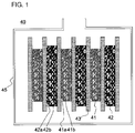
- Figure 1 is a sectional view illustrating a structure of an example of a capacitor.
- a lithium ion capacitor includes a positive electrode containing a positive electrode active material, a negative electrode containing a negative electrode active material, a separator disposed between the positive electrode and the negative electrode, and a lithium ion conductive electrolyte.
- the electrolyte contains a lithium salt and an ionic liquid.
- the lithium salt is a salt of a lithium ion serving as a first cation and a first anion.
- the ionic liquid is a molten salt of a second cation and a second anion. The first anion and the second anion are the same.
- an ionic liquid as a solvent of an electrolyte for LIBs has been studied in order to improve the safety and/or the charging voltage. It is also believed that the charging voltage can be improved by using an ionic liquid for an electrolyte in lithium ion capacitors.
- a negative electrode active material capable of intercalating and deintercalating lithium ions is used. Such a negative electrode active material is believed to reversibly cause the intercalation and deintercalation of lithium ions during charging and discharging.
- the electrolyte is the only lithium source, unlike in LIBs in which lithium ions are supplied from the positive electrode. Therefore, ease of movement of lithium ions considerably affects the charge-discharge characteristics. For example, since the degree of the interaction with lithium ions varies depending on the types of anions constituting the ionic liquid and the lithium salt, the intercalation of lithium ions into the negative electrode active material is sometimes delayed. In addition to the delay of the intercalation of lithium ions, a phenomenon in which a cation constituting the ionic liquid is intercalated into the negative electrode active material also occurs.
- the intercalation of the cation (a cation other than a lithium ion) constituting the ionic liquid into the negative electrode active material irreversibly occurs. That is, even if a charging reaction seemingly proceeds as a result of the intercalation of the cation, discharging cannot be performed because the cation is not deintercalated. Furthermore, a cation other than a lithium ion is irreversibly intercalated into the negative electrode active material. This considerably decreases the discharge capacity, and charging and discharging cannot be reversibly performed in a repeated manner. Therefore, even if an ionic liquid is used, charging and discharging cannot sometimes be reversibly performed in a stable manner. Even if the charging voltage is increased, the capacitance of the lithium ion capacitor cannot sometimes be increased.
- lithium ions are not supplied from the positive electrode, which poses a problem in that a cation other than a lithium ion is irreversibly intercalated into the negative electrode active material. That is, such a problem of the irreversible intercalation of a cation is unique to lithium ion capacitors.
- the present inventors have found that, when an anion (first anion) constituting a lithium salt is the same as an anion (second anion) constituting an ionic liquid in an electrolyte for lithium ion capacitors, the irreversible intercalation of a cation (second cation) constituting the ionic liquid into a negative electrode active material is suppressed. Although the reason for this is unclear, it is believed that the degree of the interaction with lithium ions is not differentiated. When the electrolyte containing such an anion is used for lithium ion capacitors, the intercalation of lithium ions into the negative electrode active material preferentially occurs. Therefore, it has been found that charging and discharging can be reversibly performed in a stable manner and, even when charging is performed to a high voltage such as more than 4.2 V, charging and discharging can be stably performed.
- the lithium ion capacitor can be charged and discharged at an upper-limit voltage exceeding 4.2 V.
- the upper-limit voltage is preferably 4.4 V or more and more preferably 4.6 V or more, or may be 4.8 V or more.
- the upper-limit voltage may be more than 5 V, but is preferably 5 V or less.
- the lower limit and the upper limit can be suitably combined with each other.
- the upper-limit voltage for charging is, for example, more than 4.2 V and 5 V or less or may be 4.4 V to 5 V.
- the ionic liquid has not only a function as a carrier of ions, but also a function as a solvent for dissolving the lithium salt. Therefore, the electrolyte preferably contains the ionic liquid in a particular amount.
- the electrolyte may contain a publicly known component contained in an electrolyte for lithium ion capacitors, such as an organic solvent or an additive. In the case where the electrolyte contains an organic solvent, however, gas is easily generated by decomposition when the charging voltage is increased. Therefore, the content of a component other than the lithium salt and the ionic liquid is preferably relatively low.
- the total content of the lithium salt and the ionic liquid in the electrolyte is preferably 90 mass% or more and more preferably 95 mass% or more.
- the electrolyte preferably does not contain an organic solvent such as a carbonate, and the total content of the lithium salt and the ionic liquid in the electrolyte may be 100 mass%.
- the lithium salt contained in the electrolyte is dissociated into a lithium ion and a first anion in the electrolyte, and the lithium ion serves as a charge carrier in the lithium ion capacitor.
- the first anion and a second anion constituting the ionic liquid are each preferably a bis(sulfonyl)imide anion.
- the bis(sulfonyl)imide anion is, for example, an anion which has a bis(sulfonyl)imide skeleton and in which a sulfonyl group has a fluorine atom.
- the sulfonyl group having a fluorine atom include fluorosulfonyl groups and sulfonyl groups having a fluoroalkyl group. In the fluoroalkyl group, some hydrogen atoms of the alkyl group may be substituted with fluorine atoms. Alternatively, the fluoroalkyl group may be a perfluoroalkyl group in which all hydrogen atoms are substituted with fluorine atoms.
- the sulfonyl group having a fluorine atom is preferably a fluorosulfonyl group or a perfluoroalkylsulfonyl group.
- the bis(sulfonyl)imide anion is specifically an anion represented by formula (1) below.
- X 1 and X 2 each independently represent a fluorine atom or a perfluoroalkyl group having 1 to 8 carbon atoms.
- the perfluoroalkyl group represented by X 1 and X 2 is, for example, a trifluoromethyl group, a pentafluoroethyl group, a heptafluoropropyl group, or the like.
- at least one of X 1 and X 2 preferably represents a perfluoroalkyl group, and both X 1 and X 2 more preferably represent a perfluoroalkyl group.
- the number of carbon atoms in the perfluoroalkyl group is preferably 1 to 3 and more preferably 1 or 2.
- bis(sulfonyl)imide anion examples include bis(fluorosulfonyl)imide anions (FSI - ); and bis(perfluoroalkylsulfonyl)imide anions (PFSI - ) such as a bis(trifluoromethylsulfonyl)imide anion (TFSI - ), a bis(pentafluoroethylsulfonyl)imide anion, and a fluorotrifluoromethylsulfonylimide anion ((FSO 2 )(CF 3 SO 2 )N - ).
- FSI - or TFSI - (in particular, FSI - ) is preferably used because it has a relatively low interaction with lithium ions, does not easily capture the lithium ions, and does not easily inhibit the intercalation of lithium ions into the negative electrode active material.
- FSI - or TFSI - (in particular, FSI - ) is used, lithium ions can be more smoothly intercalated into the negative electrode active material and charging and discharging can be performed more stably.
- FSI - or TFSI - can decrease the viscosity of the electrolyte and can dissolve the lithium salt well.
- Examples of the second cation constituting the ionic liquid include inorganic cations [e.g., metal cations such as alkali metal cations other than a lithium ion (e.g., sodium ion, potassium ion, rubidium ion, and cesium ion), alkaline-earth metal cations (e.g., magnesium ion and calcium ion), and transition metal cations; and ammonium cations]; organic cations such as organic onium cations; and the like.
- metal cations such as alkali metal cations other than a lithium ion (e.g., sodium ion, potassium ion, rubidium ion, and cesium ion), alkaline-earth metal cations (e.g., magnesium ion and calcium ion), and transition metal cations; and ammonium cations
- organic cations such as organic onium cations; and the like.
- the second cation is preferably an organic onium cation.
- organic onium cation examples include cations derived from an aliphatic amine, an alicyclic amine, and an aromatic amine (e.g., quaternary ammonium cations); nitrogen-containing onium cations such as cations having a nitrogen-containing heterocycle (i.e., cations derived from a cyclic amine); sulfur-containing onium cations; phosphorus-containing onium cations; and the like.
- sulfur-containing onium cation examples include sulfur-containing tertiary onium cations, for example, trialkylsulfonium cations (e.g., triC 1-10 alkylsulfonium cations) such as trimethylsulfonium cations, trihexylsulfonium cations, and dibutylethylsulfonium cations.
- trialkylsulfonium cations e.g., triC 1-10 alkylsulfonium cations
- trimethylsulfonium cations examples include trimethylsulfonium cations, trihexylsulfonium cations, and dibutylethylsulfonium cations.
- Examples of the phosphorus-containing onium cation include quaternary onium cations, for example, tetraalkylphosphonium cations (e.g., tetraC 1-10 alkylphosphonium cations) such as tetramethylphosphonium cations, tetraethylphosphonium cations, and tetraoctylphosphonium cations; and alkyl(alkoxyalkyl)phosphonium cations (e.g., triC 1-10 alkyl(C 1-5 alkoxyC 1-5 alkyl)phosphonium cations) such as triethyl(methoxymethyl)phosphonium cations, diethylmethyl(methoxymethyl)phosphonium cations, trihexyl(methoxyethyl)phosphonium cations; and the like.
- tetraalkylphosphonium cations e.g., tetraC 1-10 alky
- the total number of alkyl groups and alkoxyalkyl groups that bond to phosphorus atoms is 4, and the number of alkoxyalkyl groups is preferably 1 or 2.
- organic onium cations nitrogen-containing organic onium cations are preferred. Among them, organic onium cations having a nitrogen-containing heterocycle are preferred. When the electrolyte contains such an organic onium cation, the viscosity of the molten salt can be decreased, and thus the ionic conductivity can be improved.
- Examples of the nitrogen-containing heterocycle skeleton of the organic onium cation include five to eight-membered heterocycles having one or two nitrogen atoms as atoms constituting the ring, such as pyrrolidine, imidazoline, imidazole, pyridine, and piperidine; and five to eight-membered heterocycles having one or two nitrogen atoms and other heteroatoms (e.g., oxygen atom and sulfur atom) as atoms constituting the ring, such as morpholine.
- five to eight-membered heterocycles having one or two nitrogen atoms as atoms constituting the ring such as pyrrolidine, imidazoline, imidazole, pyridine, and piperidine
- five to eight-membered heterocycles having one or two nitrogen atoms and other heteroatoms e.g., oxygen atom and sulfur atom
- the nitrogen atoms which are atoms constituting the ring may have an organic group such as an alkyl group as a substituent.
- alkyl group include alkyl groups having 1 to 10 carbon atoms, such as a methyl group, an ethyl group, a propyl group, and an isopropyl group.
- the number of carbon atoms of the alkyl group is preferably 1 to 8, more preferably 1 to 4, and particularly preferably 1, 2, or 3.
- Nitrogen-containing organic onium cations including pyrrolidone or imidazoline as a nitrogen-containing heterocycle skeleton are particularly preferred.
- the organic onium cation having a pyrrolidone skeleton preferably has two of the above-described alkyl groups on one nitrogen atom constituting the pyrrolidine ring.
- the organic onium cation having an imidazoline skeleton preferably has one of the above-described alkyl groups on each of two nitrogen atoms constituting the imidazoline ring.
- organic onium cation having a pyrrolidine skeleton examples include N,N-dimethylpymolidinium cations, N,N-diethylpyrrolidinium cations, N-methyl-N-ethylpyrrolidinium cations, N-methyl-N-propylpyrrolidinium cations (MPPY + ), N-methyl-N-butylpyrrolidinium cations (MBPY + ), N-ethyl-N-propylpyrrolidinium cations, and the like.
- pyrrolidinium cations having a methyl group and an alkyl group with 2 to 4 carbon atoms such as MPPY + and MBPY + , are particularly preferred in view of high electrochemical stability.
- organic onium cation having an imidazoline skeleton examples include a 1,3-dimethylimidazolium cation, a 1-ethyl-3-methylimidazolium cation (EMI + ), a 1-methyl-3-propylimidazolium cation, a 1-butyl-3-methylimidazolium cation (BMI + ), a 1-ethyl-3-propylimidazolium cation, a 1-butyl-3-ethylimidazolium cation, and the like.
- imidazolium cations having a methyl group and an alkyl group with 2 to 4 carbon atoms such as EMI + and BMI + , are preferred.
- the second cation is preferably an organic onium cation having an imidazoline skeleton because the reactivity with a positive electrode active material is low and the resistance to decomposition is high even when the charging voltage is increased.
- the second cation is particularly preferably EMI + because the ionic conductivity is high.
- Specific examples of a salt of the second cation and the second anion include EMIFSI, EMITFSI, MIPFSI, and the like.
- the ionic liquid preferably contains at least EMIFSI because such an ionic liquid does not easily inhibit the intercalation of lithium ions, has high resistance to decomposition, and can dissolve a lithium salt well.
- the salt of the second cation and the second anion preferably has a low melting point because the salt needs to be in a molten state (ionic liquid) at an operational temperature of the lithium ion capacitor.
- ionic liquid a molten state
- a plurality of salts may be used in combination.
- the anion of these salts needs to be the same as the first anion, but the cation can be suitably selected from those exemplified as the second cation and can be combined.
- the ionic liquid may contain a salt that uses an EMI + cation, such as EMIFSI, and a salt that uses an MPPY + cation, such as MPPYFSI.
- the lithium concentration in the electrolyte is, for example, more than 0.8 mol/L and less than 5.5 mol/L.
- the lithium concentration is preferably 1 mol/L or more, more preferably 1.5 mol/L or more or 2 mol/L or more, and particularly preferably 2.5 mol/L or more or 3 mol/L or more.
- the lithium concentration is preferably 5 mol/L or less and more preferably 4.5 mol/L or less or 4 mol/L or less.
- the lower limit and the upper limit can be suitably combined with each other.
- the lithium concentration in the electrolyte may be 1 mol/L to 5 mol/L, 2.5 mol/L to 5 mol/L, or 3 mol/L to 5 mol/L.
- the intercalation of a cation other than a lithium ion into the negative electrode active material can be more effectively suppressed, and the influence exerted by loss of current and resistance during charging and discharging is easily reduced. Furthermore, since an unnecessary increase in the viscosity of the electrolyte can be suppressed, high ionic conductivity can be more effectively achieved. Even if the upper-limit voltage for charging is increased, stable charging and discharging can be performed more effectively. This provides an advantage in terms of an increase in the capacitance or output of the lithium ion capacitor. In addition, even when an electrode is thick or the filling amount of an electrode active material is large, charging and discharging can be efficiently performed.
- the amount of water in the electrolyte is preferably 300 ppm or less (e.g., 150 ppm or less) and more preferably 40 ppm or less.
- the amount of water in the electrolyte can be decreased by drying components (e.g., lithium salt and ionic liquid) in the electrolyte or drying the positive electrode and/or the negative electrode (or the active material thereof). The drying can be performed in a reduced pressure and may be performed under heating, if necessary.
- Electrodes (positive electrode and negative electrode) of the lithium ion capacitor each contain an electrode active material.
- the electrodes can contain an electrode current collector that holds the electrode active material.
- the electrode current collector may be a metal foil, but is preferably a metal porous body having a three-dimensional network structure in terms of achieving a high-capacitance capacitor.
- the positive electrode current collector is preferably made of aluminum, an aluminum alloy, or the like.
- the negative electrode current collector is preferably made of copper, a copper alloy, nickel, a nickel alloy, stainless steel, or the like.
- Each of the electrodes can be obtained by applying a slurry containing an electrode active material onto an electrode current collector or filling an electrode current collector with a slurry containing an electrode active material and then removing a dispersion medium contained in the slurry, and optionally rolling the current collector that holds the electrode active material.
- the slurry may contain, for example, a binder, a conductive aid, and the like, in addition to the electrode active material.
- the dispersion medium is, for example, an organic solvent such as N-methyl-2-pyrrolidone (NMP) or water.
- the type of binder is not particularly limited.
- the binder include fluororesins such as polyvinylidene fluoride (PVDF) and polytetrafluoroethylene; chlorine-containing vinyl resins such as polyvinyl chloride; polyolefin resins; rubber polymers such as styrene-butadiene rubber; polyvinylpyrrolidone; polyvinyl alcohol; cellulose derivatives (e.g., cellulose ethers) such as carboxymethyl cellulose; and the like.
- the amount of the binder is not particularly limited, but may be, for example, 0.5 parts by mass to 10 parts by mass relative to 100 parts by mass of the electrode active material.
- the type of conductive aid is not particularly limited.
- the conductive aid include carbon black such as acetylene black, conductive fiber such as carbon fiber, and the like.
- the amount of the conductive aid is not particularly limited, but may be, for example, 0.1 parts by mass to 10 parts by mass relative to 100 parts by mass of the electrode active material.
- the positive electrode active material is a material that can reversibly hold lithium and can electrochemically adsorb an anion, such as activated carbon or carbon nanotube.
- activated carbon is preferred.
- the content of the activated carbon in the positive electrode active material is preferably more than 50 mass%.
- activated carbon for use in lithium ion capacitors can be used as the activated carbon.
- raw materials for activated carbon include wood, coconut shells, spent liquor, coal or coal pitch obtained by thermal cracking of coal, heavy oil or petroleum pitch obtained by thermal cracking of heavy oil, a phenolic resin, and the like.
- a carbonized material is then activated.
- the activation method include a gas activation method and a chemical activation method.
- the gas activation method by performing contact reaction with water vapor, carbon dioxide, oxygen, or the like at high temperatures, activated carbon is obtained.
- the chemical activation method the raw materials described above are impregnated with a known chemical activation agent, heating is performed in an inert gas atmosphere to cause dehydration and oxidation reaction of the chemical activation agent, and thereby activated carbon is obtained.
- the chemical activation agent is, for example, zinc chloride, sodium hydroxide, or the like.
- the average particle diameter (median diameter in the volume-based particle size distribution, the same applies hereafter) of the activated carbon is not particularly limited, but is preferably 20 ⁇ m or less.
- the specific surface area is also not particularly limited, but is preferably about 800 m 2 /g to 3000 m 2 /g. In these ranges, the capacitance of the lithium ion capacitor can be increased and the internal resistance can be decreased.
- Examples of the negative electrode active material include a carbon material capable of intercalating and deintercalating lithium ions, lithium titanium oxide, silicon oxide, a silicon alloy, tin oxide, and a tin alloy.
- Examples of the carbon material include graphitizable carbon (soft carbon), non-graphitizable carbon (hard carbon), graphite (e.g., synthetic graphite and natural graphite), and the like. These negative electrode active materials may be used alone or in combination of two or more.
- a carbon material is preferred and graphite and/or hard carbon is particularly preferred.
- the negative electrode active material is preferably doped with lithium in advance to decrease the negative electrode potential. This increases the voltage of the capacitor, which is further advantageous to an increase in the capacitance of the lithium ion capacitor.
- the doping with lithium is performed during the fabrication of a capacitor.
- a lithium metal is accommodated in a capacitor container together with a positive electrode, a negative electrode, and a nonaqueous electrolyte, and the fabricated capacitor is kept warm in a thermostatic chamber at about 60°C. As a result, lithium ions are eluted from a lithium metal foil and intercalated into the negative electrode active material.
- the negative electrode active material is doped with lithium in such an amount that preferably 5% to 90% and more preferably 10% to 75% of the negative electrode capacitance (reversible capacitance of negative electrode) C n is filled with lithium. This sufficiently decreases the negative electrode potential, and a high-voltage capacitor is easily produced.
- Known lithium ion capacitors are designed so as to have a negative electrode capacitance C n which is much higher than the positive electrode capacitance (reversible capacitance of positive electrode) C p .
- C n negative electrode capacitance
- C p positive electrode capacitance (reversible capacitance of positive electrode)
- One of the reasons is that achieving the ability of the positive electrode to adsorb and desorb an anion makes it difficult to form a thick layer containing the positive electrode active material.
- An increase in the thickness of the layer containing the positive electrode active material makes it difficult to achieve the adsorption and desorption (charging and discharging) of an anion by the positive electrode active material in a surface layer portion. This decreases the positive electrode utilization ratio (the amount of charge actually accumulated/the theoretical value of the amount of accumulable charge calculated from the amount of the active material).
- the negative electrode active material needs to be pre-doped with a relatively large amount of lithium to decrease the negative electrode potential.
- the negative electrode capacitance C n of known lithium ion capacitors is more than ten times the positive electrode capacitance C p .
- charging and discharging can be reversibly performed to an upper-limit voltage such as more than 4.2 V in a stable manner, and thus the capacitance of the positive electrode can be effectively increased. Therefore, the ratio C n /C p of the negative electrode capacitance C n to the positive electrode capacitance C p can be set to a relatively low value.
- the positive electrode capacitance C p is a value obtained by subtracting the irreversible capacitance from a theoretical value of the amount of accumulable charge calculated from the amount of the positive electrode active material contained in the positive electrode.
- the negative electrode capacitance C n is a value obtained by subtracting the irreversible capacitance from a theoretical value of the amount of accumulable charge calculated from the amount of the negative electrode active material contained in the negative electrode.
- C p can also be evaluated based on the discharge capacity measured in an EDLC that uses a positive electrode.
- C n can also be evaluated based on the discharge capacity measured in a half cell that uses a negative electrode and a metal lithium.
- the C n /C p ratio is, for example, more than 1.1 and less than 12.5.
- the C n /C p ratio is preferably 1.2 or more and more preferably 1.3 or more or 2 or more.
- the C n /C p ratio is preferably 10 or less and more preferably 9 or less.
- the lower limit and the upper limit can be suitably combined with each other.
- the C n /C p ratio may be, for example, 1.2 to 10 or 1.3 to 10.
- the negative electrode can be pre-doped with a sufficient amount of lithium, and the voltage of the lithium ion capacitor can be more effectively increased. Furthermore, the initial voltage is easily increased, which is advantageous because the capacitance of the lithium ion capacitor can be easily increased. Moreover, there is no need to increase the volume of the positive electrode or the negative electrode to a volume larger than necessary. Therefore, the decrease in the capacitance density of the lithium ion capacitor is easily suppressed while high discharge capacity is achieved.
- a separator has ionic permeability and is disposed between the positive electrode and the negative electrode, thereby physically separating the electrodes to prevent a short-circuit.
- the separator has a porous structure and retains an electrolyte in the pores, which achieves permeation of ions.
- the separator can be made of, for example, polyolefin such as polyethylene or polypropylene, polyester such as polyethylene terephthalate, polyamide, polyimide, cellulose, glass fiber, or the like.
- the thickness of the separator is, for example, about 10 ⁇ m to 100 ⁇ m.
- FIG. 1 schematically illustrates a structure of an example of a capacitor.
- a group of plates and an electrolyte which are main components of a capacitor 40, are accommodated in a cell case 45.
- the group of plates is constituted by stacking a plurality of positive electrodes 41 and a plurality of negative electrodes 42 with separators 43 disposed therebetween.
- Each of the positive electrodes 41 includes a positive electrode current collector 41a having a three-dimensional network structure and a particulate positive electrode active material 41b that fills communicating pores of the positive electrode current collector 41a.
- Each of the negative electrodes 42 includes a negative electrode current collector 42a having a three-dimensional network structure and a particulate negative electrode active material 42b that fills communicating pores of the negative electrode current collector 42a.
- the group of plates is not limited to the stacked structure, but may be constituted by winding the positive electrode 41 and the negative electrode 42 with the separator 43 disposed therebetween.
- the size of the negative electrode 42 is desirably set to be larger than that of the positive electrode 41 as illustrated in Fig. 1 in order to prevent lithium from precipitating on the negative electrode 42.
- a lithium ion capacitor was produced by the following procedure.
- An activated carbon powder (specific surface area: 2300 m 2 /g, average particle diameter: about 5 ⁇ m), acetylene black serving as a conductive aid, PVDF (NMP solution containing PVDF at a concentration of 12 mass%) serving as a binder, and NMP serving as a dispersion medium were mixed and stirred using a mixer to prepare a positive electrode mixture scurry.
- the content of the activated carbon was 21.5 mass%
- the content of the acetylene black was 0.76 mass%
- the content of the PVDF was 20.6 mass%.
- the prepared positive electrode mixture slurry was applied onto one surface (roughened surface) of an aluminum foil (thickness: 20 ⁇ m) serving as a current collector using a doctor blade to form a coating film having a thickness of 100 ⁇ m.
- the coating film was dried at 100°C for 30 minutes. The dried film was rolled using a pair of rolls to produce a positive electrode having a thickness of 65 ⁇ m.
- a hard carbon powder (average particle diameter: 10 ⁇ m), acetylene black serving as a conductive aid, PVDF (NMP solution containing PVDF at a concentration of 12 mass%) serving as a binder, and NMP serving as a dispersion medium were mixed and stirred using a mixer to prepare a negative electrode mixture slurry.
- the content of the hard carbon was 28.0 mass%
- the content of the acetylene black was 2.7 mass%
- the content of the PVDF was 13.3 mass%.
- the prepared negative electrode mixture slurry was applied onto one surface of a punched copper foil (thickness: 20 ⁇ m, opening diameter: 50 ⁇ m, opening ratio: 50%) serving as a current collector using a doctor blade to form a coating film having a thickness of 200 ⁇ m.
- the coating film was dried at 100°C for 30 minutes. The dried film was rolled using a pair of rolls to produce a negative electrode having a thickness of 120 ⁇ m.
- a lithium foil (thickness: 50 ⁇ m) was pressure-bonded to one surface of a punched copper foil (thickness: 20 ⁇ m, opening diameter: 50 ⁇ m, opening ratio: 50%, 2 cm x 2 cm) serving as a current collector to produce a lithium electrode.
- a lead made of nickel was welded on another surface of the current collector.
- the positive electrode produced in (1) and the negative electrode produced in (2) were each cut into a size of 1.5 cm x 1.5 cm, and a portion of the mixture having a width of 0.5 mm was removed along one side to form a current collector-exposed portion.
- a lead made of aluminum was welded to the current collector-exposed portion of the positive electrode and a lead made of nickel was welded to the current collector-exposed portion of the negative electrode.
- the area of a portion where the mixture was present was 1.5 cm -2 .
- a cellulose separator (thickness: 60 ⁇ m) was disposed between the positive electrode and the negative electrode so that the positive electrode and the negative electrode were stacked onto each other. Thus, a group of plates of a single cell was produced. Furthermore, the lithium electrode was disposed on the negative electrode side of the group of plates with a polyolefin separator (a stack of a polyethylene microporous membrane and a polypropylene microporous membrane) disposed between the lithium electrode and the group of plates. The resulting stack was accommodated in a cell case made of an aluminum laminate sheet.
- an electrolyte was poured into the cell case so that the positive electrode, the negative electrode, and the separator were impregnated with the electrolyte.
- the electrolyte was an EMIFSI solution containing LiFSI as a lithium salt at a concentration of 1.0 mol/L.
- the cell case was sealed while the pressure was reduced using a vacuum sealer.
- the negative electrode and the lithium electrode were connected to each other through a lead at the outside of the cell case. Charging was performed at a current of 0.2 mA/cm 2 until the voltage reached 0 V to pre-dope the negative electrode active material with lithium. Subsequently, 0.33 mAh of discharging was performed at a current of 0.2 mA/cm 2 . The voltage (initial voltage) after the discharging was measured.
- a lithium ion capacitor was produced.
- the amount of water in the electrolyte contained in the lithium ion capacitor was measured by a Karl Fischer method, and the amount was 108 ppm.
- Two positive electrodes were prepared, and a cellulose separator (thickness: 60 ⁇ m) was disposed between the positive electrodes to form a group of plates. Subsequently, the group of plates and the above-described electrolyte were accommodated in an aluminum laminate bag to complete an EDLC.
- the obtained EDLC was charged and discharged in a voltage range of 0 to 4 V, and the reversible capacitance C p of the positive electrode was determined from the discharge capacity.
- the negative electrode and the above-described lithium electrode were prepared, and a cellulose separator (thickness: 60 ⁇ m) was disposed therebetween to form a group of plates.
- a half cell was produced using the formed group of plates and the above-described electrolyte. The half cell was charged and discharged in a voltage range of 0 to 2.5 V, and the reversible capacitance C n of the negative electrode was determined from the discharge capacity.
- the C p /C n ratio was calculated by dividing C p by C n .
- Charging was performed at a current of 0.4 mA/cm 2 until the voltage reached 3.8 V, and discharging was performed until the voltage reached 3.0 V. Subsequently, charging and discharging were performed in the same manner as above, except that the upper-limit voltage for charging was increased to 5.0 V in increments of 0.2 V. Thus, the upper-limit voltage at which charging can be performed was measured.
- a lithium ion capacitor was produced and evaluated in the same manner as in Example 1, except that an electrolyte containing a lithium salt and a medium (ionic liquid or organic solvent) listed in Table 1 was used as the electrolyte.
- a mixed solvent containing EC and DEC at a volume ratio of 1:1 was used as the medium.
- Table 1 shows the results.
- Example 1 LiFSI EMIFSI 0.30 8.3 0.31 5.0
- Example 2 LiFSI BMIFSI 0.29 5.0
- Example 3 LiFSI MPPYFSI 0.30 5.0
- Example 4 LiFSI MBPYFSI 0.28 5.0
- Comparative Example 1 LiPF 6 EC+DEC 0.18 4.2
- Comparative Example 2 LiTFSI EMIFSI 0.03 (5.0) Comparative Example 3 LiTFSI EPPYFSI 0.02 (5.0)
- Comparative Examples 2 and 3 the ionic liquid was used, but the types of anions in the lithium salt and the ionic liquid were different. In Comparative Examples 2 and 3, even when the upper-limit voltage for charging was increased to 5.0 V, the swelling of the lithium ion capacitor in Comparative Example 1 was not observed. In Comparative Examples 2 and 3, however, the discharge capacity of the lithium ion capacitor considerably decreased, and the discharge capacity was 1/10 or less of C p . As a result of the evaluation of the charge capacity in Comparative Examples 2 and 3, the charge capacity was about 0.15 mAh, which was half of C p . That is, in Comparative Examples 2 and 3, charging was performed to some extent, but the discharge capacity relative to the charge capacity was considerably low. Therefore, charging and discharging could not be reversibly performed in a stable manner at a high charging voltage.
- the discharge capacity of the lithium ion capacitor was substantially equal to C p , and the utilization efficiently of the positive electrode was high. Therefore, in Examples, a high-capacitance lithium ion capacitor was produced.
- a lithium ion capacitor was produced in the same manner as in Example 1, except that the concentration of the lithium salt in the electrolyte was changed to that listed in Table 2. The upper-limit voltage and the discharge capacity were evaluated.
- Table 2 shows the results. [Table 2] Concentration of Li salt (mol/L) Discharge capacity (mAh) Upper-limit voltage (V) C p (mAh) C n /C p Example 5 0.8 0.30 8.3 0.24 5.0 Example 1 1.0 0.31 5.0 Example 6 3.0 0.35 5.0 Example 7 5.0 0.33 5.0 Example 8 5.5 0.21 5.0
- Example 6 even when the upper-limit voltage for charging was 5 V, charging and discharging could be stably performed as in the case of Example 1, and the capacity was equal to or higher than C p .
- Example 5 and 8 although the discharge capacity of the lithium ion capacitor was slightly lower than C p , charging and discharging could be performed even when the upper-limit voltage for charging was 5 V.
- the charge capacity of the lithium ion capacitor evaluated was more than 0.3 mAh, which was as high as C p .
- the concentration of the lithium salt is preferably more than 0.8 mol/L and less than 5.5 mol/L.
- a negative electrode and a lithium ion capacitor were produced in the same manner as in Example 1, except that the thickness of the coating film of the negative electrode mixture slurry and the thickness of the negative electrode were changed to those listed in Table 3.
- the upper-limit voltage and the discharge capacity were evaluated in the same manner as in Example 1.
- the thickness of the coating film was less than 50 ⁇ m, the negative electrode mixture slurry was applied onto the current collector using a spatula instead of the doctor blade.
- Table 3 shows the results. Table 3 also shows the initial voltage of each lithium ion capacitor.
- Thickness of coating film ( ⁇ m) Thickness of negative electrode ( ⁇ m) C p (mAh) C n /C p
- Initial voltage (V) Discharge capacity (mAh) Upper-limit voltage (V)
- Example 9 300 170 3.73 12.5 2.99 0.31 5.0
- Example 10 150 95 1.87 6.3 2.86 0.31 5.0
- Example 11 100 70 1.25 4.2 2.81 0.30 5.0
- Example 12 50 45 0.64 2.1 2.62 0.28 5.0
- Example 13 40 35 0.38 1.3 2.14 0.25 5.0
- Example 14 35 33 0.32 1.1 1.63 0.19 5.0
- Example 9 even when the upper-limit voltage for charging was 5 V, charging and discharging could be stably performed as in the case of Example 1, and the discharge capacity was as high as C p . In these Examples, the initial voltage was also high. In Example 14, the initial voltage and the discharge capacity of the lithium ion capacitor were lower than those of other Examples. However, even when the upper-limit voltage for charging was 5V, charging and discharging could be stably performed. When the initial voltage is low, a charging state needs to be kept to compensate for the difference between the required voltage and the initial voltage, and thus the capacity tends to decrease. Therefore, the C n /C p ratio is preferably more than 1.1 in view of increases in initial voltage and discharge capacity.
- Example 9 the C n /C p ratio is larger than that in Example 1, but the initial voltage is substantially equal to that in Example 1. This is because, as the amount of lithium doped into the negative electrode comes close to the saturation amount, the negative electrode potential reaches substantially 0 V relative to a Li metal. Therefore, even if the C n /C p ratio is excessively increased, the discharge capacity of the lithium ion capacitor substantially does not change. However, an increase in the amount of the negative electrode results in an increase in the volume of the lithium ion capacitor in the cell. Thus, the capacitance density of the lithium ion capacitor decreases. Accordingly, the C n /C p ratio is preferably less than 12.5 in view of suppressing the decrease in the capacitance density of the lithium ion capacitor while achieving sufficient discharge capacity.
- the lithium ion capacitor of the present invention charging and discharging can be reversibly performed in a stable manner even when the charging voltage is increased.
- a high-capacitance lithium ion capacitor can be produced. Therefore, the lithium ion capacitor can be applied to various power storage devices that require a high capacitance.
Landscapes
- Engineering & Computer Science (AREA)
- Power Engineering (AREA)
- Chemical & Material Sciences (AREA)
- Microelectronics & Electronic Packaging (AREA)
- Chemical Kinetics & Catalysis (AREA)
- Electrochemistry (AREA)
- Materials Engineering (AREA)
- Electric Double-Layer Capacitors Or The Like (AREA)
- Secondary Cells (AREA)
Abstract
Description
- The present invention relates to a lithium ion capacitor and a method for charging and discharging the lithium ion capacitor. More specifically, the present invention relates to an improvement in an electrolyte for the lithium ion capacitor.
- With environmental problems being highlighted, systems for converting clean energy such as sunlight or wind power into electric power and stung the electric power as an electric energy have been actively developed. Known examples of such power storage devices include lithium ion secondary batteries (LIBs), electric double-layer capacitors (EDLCs), lithium ion capacitors, and the like. In recent years, attention has been paid to capacitors such as EDLCs and lithium ion capacitors in terms of excellent instantaneous charge-discharge characteristics, high-output characteristics, and ease of handling.
- Such capacitors have a capacitance lower than that of LIBs or the like, but lithium ion capacitors have advantages of both LIBs and EDLCs and tend to have a relatively high capacitance. Therefore, such lithium ion capacitors are promising for use in various applications. Lithium ion capacitors generally include a positive electrode containing activated carbon or the like as a positive electrode active material, a negative electrode containing, as a negative electrode active material, a carbon material or the like capable of intercalating and deintercalating lithium ions, and a non-aqueous electrolyte. In such a lithium ion capacitor, a carbon material capable of intercalating and deintercalating lithium ions is used in the negative electrode. Therefore, the negative electrode potential is decreased by pre-doping the negative electrode with lithium, and thus a somewhat high capacitance is easily achieved.
- The non-aqueous electrolyte of the lithium ion capacitor is generally an organic solvent solution (organic electrolyte) containing an electrolyte such as a lithium salt. The organic solvent of the electrolyte is, for example, ethylene carbonate (EC), diethyl carbonate (DEC) or the like (PTL 1). It has been also studied that an organic electrolyte containing an ionic liquid in addition to the electrolyte and the organic solvent is used for lithium ion capacitors (PTL 2).
- It has been also studied in the field of LIBs that an ionic liquid is used as a solvent for an electrolyte (PTL 3). The ionic liquid is a salt that includes a cation and an anion and has liquidity in a molten state. The ionic liquid has ionic conductivity at least in a molten state.
-
- PTL 1:
Japanese Unexamined Patent Application Publication No. 2007-294539 - PTL 2:
Japanese Unexamined Patent Application Publication No. 2012-142340 - PTL 3:
Japanese Unexamined Patent Application Publication No. 2010-97922 - Among capacitors, lithium ion capacitors can have a relatively high charging voltage and thus are advantageous in terms of an increase in capacitance. However, as described in PTL 1 and PTL 2, an organic electrolyte is used in lithium ion capacitors. When the charging voltage of a lithium ion capacitor that uses an organic electrolyte is increased, the positive electrode potential increases during charging, which causes oxidative decomposition of an organic solvent contained in the organic electrolyte at the positive electrode. As a result, a large amount of gas is generated, which makes it difficult to stably perform charging and discharging.
- In PTL 3, an ionic liquid is used as a solvent of an electrolyte for LIBs. The ionic liquid is not easily decomposed compared with EC and DEC. Therefore, it is believed that the upper-limit voltage for charging can be increased because if an ionic liquid is also used in lithium ion capacitors, there is no need to use an organic solvent; or even if an organic solvent is used, the amount of the organic solvent can be decreased. However, the present inventors have found that, in lithium ion capacitors, even when an ionic liquid is used, charging and discharging cannot sometimes be reversibly performed unlike the case of LIBs.
- In view of the foregoing, one aspect of the present invention relates to a lithium ion capacitor including a positive electrode containing a positive electrode active material, a negative electrode containing a negative electrode active material, a separator disposed between the positive electrode and the negative electrode, and a lithium ion conductive electrolyte. The electrolyte contains a lithium salt and an ionic liquid. The lithium salt is a salt of a lithium ion serving as a first cation and a first anion, and the ionic liquid is a molten salt of a second cation and a second anion. The first anion and the second anion are the same.
- In such a lithium ion capacitor, charging and discharging can be reversibly performed in a stable manner. Furthermore, in such a lithium ion capacitor, charging and discharging can be stably performed even when charging is performed to an upper-limit voltage such as more than 4.2 V.
- The total content of the lithium salt and the ionic liquid in the electrolyte may be, for example, 90 mass% or more. Even when the upper-limit voltage for charging is high, charging and discharging can be performed more stably by using such an electrolyte. Furthermore, even when a solvent having low resistance to decomposition (e.g., an organic solvent such as a carbonate) is contained, the amount of the solvent can be decreased, and thus the generation of gas caused by decomposition of the solvent can be effectively suppressed.
- The first anion and the second anion are each preferably a bis(fluorosulfonyl)imide anion or a bis(trifluoromethylsulfonyl)imide anion. When the electrolyte contains such an anion, the viscosity of the electrolyte is easily decreased and lithium ions can be smoothly intercalated into the negative electrode active material, which is advantageous in reversibly performing charging and discharging.
- The second cation is preferably an organic onium cation. The organic onium cation preferably has a nitrogen-containing heterocycle. When the electrolyte contains such a second cation, the melting point of the molten salt can be decreased, and therefore ions can be more smoothly moved.
- The electrolyte preferably has a lithium concentration of 1 mol/L to 5 mol/L. By using the electrolyte having such a lithium concentration, the capacitance or output of the lithium ion capacitor can be more effectively increased.
- The negative electrode active material preferably contains at least one selected from the group consisting of graphite and hard carbon. Such a negative electrode active material has good properties of intercalating and deintercalating lithium ions, and thus charging and discharging can be more smoothly performed.
- The ratio Cn /Cp of a reversible capacitance Cn of the negative electrode to a reversible capacitance Cp of the positive electrode may be, for example, 1.2 to 10. At such a reversible capacitance ratio, the negative electrode can be pre-doped with a sufficient amount of lithium, and thus the capacitance or voltage of the lithium ion capacitor can be more effectively increased.
- Another aspect of the present invention relates to a method for charging and discharging a lithium ion capacitor, the method including a step of charging and discharging the lithium ion capacitor at an upper-limit voltage of more than 4.2 V and 5 V or less. The lithium ion capacitor includes a positive electrode containing a positive electrode active material, a negative electrode containing a negative electrode active material capable of intercalating and deintercalating lithium ions, a separator disposed between the positive electrode and the negative electrode, and a lithium ion conductive electrolyte. The electrolyte contains a lithium salt and an ionic liquid; the lithium salt is a salt of a lithium ion serving as a first cation and a first anion, and the ionic liquid is a molten salt of a second cation and a second anion; and the first anion and the second anion are the same. When the electrolyte has the above-described composition, charging and discharging can be reversibly performed in a stable manner even at a high upper-limit voltage for charging of more than 4.2 V and 5 V or less.
- According to the present invention, even when the electrolyte contains an ionic liquid, the lithium ion capacitor can be reversibly charged and discharged in a stable manner. Furthermore, even when charging is performed to a high upper-limit voltage, generation of gas, or the like does not easily occur. Therefore, a high-capacitance lithium ion capacitor can be produced.
- [
Fig. 1] Figure 1 is a sectional view illustrating a structure of an example of a capacitor. - A lithium ion capacitor includes a positive electrode containing a positive electrode active material, a negative electrode containing a negative electrode active material, a separator disposed between the positive electrode and the negative electrode, and a lithium ion conductive electrolyte. The electrolyte contains a lithium salt and an ionic liquid. The lithium salt is a salt of a lithium ion serving as a first cation and a first anion. The ionic liquid is a molten salt of a second cation and a second anion. The first anion and the second anion are the same.
- Use of an ionic liquid as a solvent of an electrolyte for LIBs has been studied in order to improve the safety and/or the charging voltage. It is also believed that the charging voltage can be improved by using an ionic liquid for an electrolyte in lithium ion capacitors. In the negative electrode for LIBs, a negative electrode active material capable of intercalating and deintercalating lithium ions is used. Such a negative electrode active material is believed to reversibly cause the intercalation and deintercalation of lithium ions during charging and discharging.
- In lithium ion capacitors, however, the electrolyte is the only lithium source, unlike in LIBs in which lithium ions are supplied from the positive electrode. Therefore, ease of movement of lithium ions considerably affects the charge-discharge characteristics. For example, since the degree of the interaction with lithium ions varies depending on the types of anions constituting the ionic liquid and the lithium salt, the intercalation of lithium ions into the negative electrode active material is sometimes delayed. In addition to the delay of the intercalation of lithium ions, a phenomenon in which a cation constituting the ionic liquid is intercalated into the negative electrode active material also occurs. The intercalation of the cation (a cation other than a lithium ion) constituting the ionic liquid into the negative electrode active material irreversibly occurs. That is, even if a charging reaction seemingly proceeds as a result of the intercalation of the cation, discharging cannot be performed because the cation is not deintercalated. Furthermore, a cation other than a lithium ion is irreversibly intercalated into the negative electrode active material. This considerably decreases the discharge capacity, and charging and discharging cannot be reversibly performed in a repeated manner. Therefore, even if an ionic liquid is used, charging and discharging cannot sometimes be reversibly performed in a stable manner. Even if the charging voltage is increased, the capacitance of the lithium ion capacitor cannot sometimes be increased.
- In LIBs, a large amount of lithium ions is supplied from the positive electrode during charging, and thus the intercalation of lithium ions into the negative electrode active material is not inhibited. Therefore, use of an ionic liquid does not pose the above-described problem.
- In lithium ion capacitors, however, lithium ions are not supplied from the positive electrode, which poses a problem in that a cation other than a lithium ion is irreversibly intercalated into the negative electrode active material. That is, such a problem of the irreversible intercalation of a cation is unique to lithium ion capacitors.
- The present inventors have found that, when an anion (first anion) constituting a lithium salt is the same as an anion (second anion) constituting an ionic liquid in an electrolyte for lithium ion capacitors, the irreversible intercalation of a cation (second cation) constituting the ionic liquid into a negative electrode active material is suppressed. Although the reason for this is unclear, it is believed that the degree of the interaction with lithium ions is not differentiated. When the electrolyte containing such an anion is used for lithium ion capacitors, the intercalation of lithium ions into the negative electrode active material preferentially occurs. Therefore, it has been found that charging and discharging can be reversibly performed in a stable manner and, even when charging is performed to a high voltage such as more than 4.2 V, charging and discharging can be stably performed.
- In a method for charging and discharging a lithium ion capacitor according to the present invention, the lithium ion capacitor can be charged and discharged at an upper-limit voltage exceeding 4.2 V. Thus, the capacity of a positive electrode active material can be effectively used, and the capacitance of the lithium ion capacitor can be considerably increased. The upper-limit voltage is preferably 4.4 V or more and more preferably 4.6 V or more, or may be 4.8 V or more. The upper-limit voltage may be more than 5 V, but is preferably 5 V or less. The lower limit and the upper limit can be suitably combined with each other. The upper-limit voltage for charging is, for example, more than 4.2 V and 5 V or less or may be 4.4 V to 5 V.
- In the electrolyte, the ionic liquid has not only a function as a carrier of ions, but also a function as a solvent for dissolving the lithium salt. Therefore, the electrolyte preferably contains the ionic liquid in a particular amount. The electrolyte may contain a publicly known component contained in an electrolyte for lithium ion capacitors, such as an organic solvent or an additive. In the case where the electrolyte contains an organic solvent, however, gas is easily generated by decomposition when the charging voltage is increased. Therefore, the content of a component other than the lithium salt and the ionic liquid is preferably relatively low. Specifically, the total content of the lithium salt and the ionic liquid in the electrolyte is preferably 90 mass% or more and more preferably 95 mass% or more. In particular, the electrolyte preferably does not contain an organic solvent such as a carbonate, and the total content of the lithium salt and the ionic liquid in the electrolyte may be 100 mass%.
- If the total content of the lithium salt and the ionic liquid is high, the decomposition of the electrolyte tends to be more effectively suppressed even when the charging voltage is increased. Thus, charging and discharging can be performed in a more stable manner.
- Hereafter, the components of the electrolyte will be described in detail.
- The lithium salt contained in the electrolyte is dissociated into a lithium ion and a first anion in the electrolyte, and the lithium ion serves as a charge carrier in the lithium ion capacitor.
- The first anion and a second anion constituting the ionic liquid are each preferably a bis(sulfonyl)imide anion.
- The bis(sulfonyl)imide anion is, for example, an anion which has a bis(sulfonyl)imide skeleton and in which a sulfonyl group has a fluorine atom. Examples of the sulfonyl group having a fluorine atom include fluorosulfonyl groups and sulfonyl groups having a fluoroalkyl group. In the fluoroalkyl group, some hydrogen atoms of the alkyl group may be substituted with fluorine atoms. Alternatively, the fluoroalkyl group may be a perfluoroalkyl group in which all hydrogen atoms are substituted with fluorine atoms. The sulfonyl group having a fluorine atom is preferably a fluorosulfonyl group or a perfluoroalkylsulfonyl group.
- The bis(sulfonyl)imide anion is specifically an anion represented by formula (1) below.

- The perfluoroalkyl group represented by X1 and X2 is, for example, a trifluoromethyl group, a pentafluoroethyl group, a heptafluoropropyl group, or the like. In order to decrease the viscosity of the ionic liquid, at least one of X1 and X2 preferably represents a perfluoroalkyl group, and both X1 and X2 more preferably represent a perfluoroalkyl group. Furthermore, in order to decrease the viscosity of the ionic liquid, the number of carbon atoms in the perfluoroalkyl group is preferably 1 to 3 and more preferably 1 or 2.
- Specific examples of the bis(sulfonyl)imide anion include bis(fluorosulfonyl)imide anions (FSI-); and bis(perfluoroalkylsulfonyl)imide anions (PFSI-) such as a bis(trifluoromethylsulfonyl)imide anion (TFSI-), a bis(pentafluoroethylsulfonyl)imide anion, and a fluorotrifluoromethylsulfonylimide anion ((FSO2)(CF3SO2)N-).
- Among these anions, FSI- or TFSI- (in particular, FSI-) is preferably used because it has a relatively low interaction with lithium ions, does not easily capture the lithium ions, and does not easily inhibit the intercalation of lithium ions into the negative electrode active material. When FSI- or TFSI- (in particular, FSI-) is used, lithium ions can be more smoothly intercalated into the negative electrode active material and charging and discharging can be performed more stably. Furthermore, FSI- or TFSI- can decrease the viscosity of the electrolyte and can dissolve the lithium salt well.
- Examples of the second cation constituting the ionic liquid include inorganic cations [e.g., metal cations such as alkali metal cations other than a lithium ion (e.g., sodium ion, potassium ion, rubidium ion, and cesium ion), alkaline-earth metal cations (e.g., magnesium ion and calcium ion), and transition metal cations; and ammonium cations]; organic cations such as organic onium cations; and the like.
- The second cation is preferably an organic onium cation. Examples of the organic onium cation include cations derived from an aliphatic amine, an alicyclic amine, and an aromatic amine (e.g., quaternary ammonium cations); nitrogen-containing onium cations such as cations having a nitrogen-containing heterocycle (i.e., cations derived from a cyclic amine); sulfur-containing onium cations; phosphorus-containing onium cations; and the like.
- Examples of the sulfur-containing onium cation include sulfur-containing tertiary onium cations, for example, trialkylsulfonium cations (e.g., triC1-10 alkylsulfonium cations) such as trimethylsulfonium cations, trihexylsulfonium cations, and dibutylethylsulfonium cations.
- Examples of the phosphorus-containing onium cation include quaternary onium cations, for example, tetraalkylphosphonium cations (e.g., tetraC1-10 alkylphosphonium cations) such as tetramethylphosphonium cations, tetraethylphosphonium cations, and tetraoctylphosphonium cations; and alkyl(alkoxyalkyl)phosphonium cations (e.g., triC1-10 alkyl(C1-5 alkoxyC1-5 alkyl)phosphonium cations) such as triethyl(methoxymethyl)phosphonium cations, diethylmethyl(methoxymethyl)phosphonium cations, trihexyl(methoxyethyl)phosphonium cations; and the like. In the alkyl(alkoxyalkyl)phosphonium cations, the total number of alkyl groups and alkoxyalkyl groups that bond to phosphorus atoms is 4, and the number of alkoxyalkyl groups is preferably 1 or 2.
- Among the organic onium cations, nitrogen-containing organic onium cations are preferred. Among them, organic onium cations having a nitrogen-containing heterocycle are preferred. When the electrolyte contains such an organic onium cation, the viscosity of the molten salt can be decreased, and thus the ionic conductivity can be improved.
- Examples of the nitrogen-containing heterocycle skeleton of the organic onium cation include five to eight-membered heterocycles having one or two nitrogen atoms as atoms constituting the ring, such as pyrrolidine, imidazoline, imidazole, pyridine, and piperidine; and five to eight-membered heterocycles having one or two nitrogen atoms and other heteroatoms (e.g., oxygen atom and sulfur atom) as atoms constituting the ring, such as morpholine.
- The nitrogen atoms which are atoms constituting the ring may have an organic group such as an alkyl group as a substituent. Examples of the alkyl group include alkyl groups having 1 to 10 carbon atoms, such as a methyl group, an ethyl group, a propyl group, and an isopropyl group. The number of carbon atoms of the alkyl group is preferably 1 to 8, more preferably 1 to 4, and particularly preferably 1, 2, or 3.
- Nitrogen-containing organic onium cations including pyrrolidone or imidazoline as a nitrogen-containing heterocycle skeleton are particularly preferred. The organic onium cation having a pyrrolidone skeleton preferably has two of the above-described alkyl groups on one nitrogen atom constituting the pyrrolidine ring. The organic onium cation having an imidazoline skeleton preferably has one of the above-described alkyl groups on each of two nitrogen atoms constituting the imidazoline ring.
- Specific examples of the organic onium cation having a pyrrolidine skeleton include N,N-dimethylpymolidinium cations, N,N-diethylpyrrolidinium cations, N-methyl-N-ethylpyrrolidinium cations, N-methyl-N-propylpyrrolidinium cations (MPPY+), N-methyl-N-butylpyrrolidinium cations (MBPY+), N-ethyl-N-propylpyrrolidinium cations, and the like. Among them, pyrrolidinium cations having a methyl group and an alkyl group with 2 to 4 carbon atoms, such as MPPY+ and MBPY+, are particularly preferred in view of high electrochemical stability.
- Specific examples of the organic onium cation having an imidazoline skeleton include a 1,3-dimethylimidazolium cation, a 1-ethyl-3-methylimidazolium cation (EMI+), a 1-methyl-3-propylimidazolium cation, a 1-butyl-3-methylimidazolium cation (BMI+), a 1-ethyl-3-propylimidazolium cation, a 1-butyl-3-ethylimidazolium cation, and the like. Among them, imidazolium cations having a methyl group and an alkyl group with 2 to 4 carbon atoms, such as EMI+ and BMI+, are preferred.
- The second cation is preferably an organic onium cation having an imidazoline skeleton because the reactivity with a positive electrode active material is low and the resistance to decomposition is high even when the charging voltage is increased. The second cation is particularly preferably EMI+ because the ionic conductivity is high. Specific examples of a salt of the second cation and the second anion include EMIFSI, EMITFSI, MIPFSI, and the like. The ionic liquid preferably contains at least EMIFSI because such an ionic liquid does not easily inhibit the intercalation of lithium ions, has high resistance to decomposition, and can dissolve a lithium salt well.
- The salt of the second cation and the second anion preferably has a low melting point because the salt needs to be in a molten state (ionic liquid) at an operational temperature of the lithium ion capacitor. To control the melting point of the ionic liquid within an appropriate range, a plurality of salts may be used in combination. Herein, the anion of these salts needs to be the same as the first anion, but the cation can be suitably selected from those exemplified as the second cation and can be combined. For example, the ionic liquid may contain a salt that uses an EMI+ cation, such as EMIFSI, and a salt that uses an MPPY+ cation, such as MPPYFSI.
- The lithium concentration in the electrolyte is, for example, more than 0.8 mol/L and less than 5.5 mol/L. The lithium concentration is preferably 1 mol/L or more, more preferably 1.5 mol/L or more or 2 mol/L or more, and particularly preferably 2.5 mol/L or more or 3 mol/L or more. The lithium concentration is preferably 5 mol/L or less and more preferably 4.5 mol/L or less or 4 mol/L or less. The lower limit and the upper limit can be suitably combined with each other. The lithium concentration in the electrolyte may be 1 mol/L to 5 mol/L, 2.5 mol/L to 5 mol/L, or 3 mol/L to 5 mol/L.
- When the lithium concentration is within the above range, the intercalation of a cation other than a lithium ion into the negative electrode active material can be more effectively suppressed, and the influence exerted by loss of current and resistance during charging and discharging is easily reduced. Furthermore, since an unnecessary increase in the viscosity of the electrolyte can be suppressed, high ionic conductivity can be more effectively achieved. Even if the upper-limit voltage for charging is increased, stable charging and discharging can be performed more effectively. This provides an advantage in terms of an increase in the capacitance or output of the lithium ion capacitor. In addition, even when an electrode is thick or the filling amount of an electrode active material is large, charging and discharging can be efficiently performed.
- A large amount of water in the electrolyte makes it difficult to increase the upper-limit voltage for charging. Therefore, the amount of water in the electrolyte is preferably 300 ppm or less (e.g., 150 ppm or less) and more preferably 40 ppm or less. The amount of water in the electrolyte can be decreased by drying components (e.g., lithium salt and ionic liquid) in the electrolyte or drying the positive electrode and/or the negative electrode (or the active material thereof). The drying can be performed in a reduced pressure and may be performed under heating, if necessary.
- Hereafter, components other than the electrolyte in the lithium ion capacitor will be described in detail.
- Electrodes (positive electrode and negative electrode) of the lithium ion capacitor each contain an electrode active material. In addition to the electrode active material, the electrodes can contain an electrode current collector that holds the electrode active material.
- The electrode current collector may be a metal foil, but is preferably a metal porous body having a three-dimensional network structure in terms of achieving a high-capacitance capacitor. The positive electrode current collector is preferably made of aluminum, an aluminum alloy, or the like. The negative electrode current collector is preferably made of copper, a copper alloy, nickel, a nickel alloy, stainless steel, or the like.
- Each of the electrodes can be obtained by applying a slurry containing an electrode active material onto an electrode current collector or filling an electrode current collector with a slurry containing an electrode active material and then removing a dispersion medium contained in the slurry, and optionally rolling the current collector that holds the electrode active material. The slurry may contain, for example, a binder, a conductive aid, and the like, in addition to the electrode active material. The dispersion medium is, for example, an organic solvent such as N-methyl-2-pyrrolidone (NMP) or water.
- The type of binder is not particularly limited. Examples of the binder include fluororesins such as polyvinylidene fluoride (PVDF) and polytetrafluoroethylene; chlorine-containing vinyl resins such as polyvinyl chloride; polyolefin resins; rubber polymers such as styrene-butadiene rubber; polyvinylpyrrolidone; polyvinyl alcohol; cellulose derivatives (e.g., cellulose ethers) such as carboxymethyl cellulose; and the like. The amount of the binder is not particularly limited, but may be, for example, 0.5 parts by mass to 10 parts by mass relative to 100 parts by mass of the electrode active material.
- The type of conductive aid is not particularly limited. Examples of the conductive aid include carbon black such as acetylene black, conductive fiber such as carbon fiber, and the like. The amount of the conductive aid is not particularly limited, but may be, for example, 0.1 parts by mass to 10 parts by mass relative to 100 parts by mass of the electrode active material.
- The positive electrode active material is a material that can reversibly hold lithium and can electrochemically adsorb an anion, such as activated carbon or carbon nanotube. Among them, activated carbon is preferred. For example, the content of the activated carbon in the positive electrode active material is preferably more than 50 mass%.
- Publicly known activated carbon for use in lithium ion capacitors can be used as the activated carbon. Examples of raw materials for activated carbon include wood, coconut shells, spent liquor, coal or coal pitch obtained by thermal cracking of coal, heavy oil or petroleum pitch obtained by thermal cracking of heavy oil, a phenolic resin, and the like.
- In general, a carbonized material is then activated. Examples of the activation method include a gas activation method and a chemical activation method. In the gas activation method, by performing contact reaction with water vapor, carbon dioxide, oxygen, or the like at high temperatures, activated carbon is obtained. In the chemical activation method, the raw materials described above are impregnated with a known chemical activation agent, heating is performed in an inert gas atmosphere to cause dehydration and oxidation reaction of the chemical activation agent, and thereby activated carbon is obtained. The chemical activation agent is, for example, zinc chloride, sodium hydroxide, or the like.
- The average particle diameter (median diameter in the volume-based particle size distribution, the same applies hereafter) of the activated carbon is not particularly limited, but is preferably 20 µm or less. The specific surface area is also not particularly limited, but is preferably about 800 m2/g to 3000 m2/g. In these ranges, the capacitance of the lithium ion capacitor can be increased and the internal resistance can be decreased.
- Examples of the negative electrode active material include a carbon material capable of intercalating and deintercalating lithium ions, lithium titanium oxide, silicon oxide, a silicon alloy, tin oxide, and a tin alloy. Examples of the carbon material include graphitizable carbon (soft carbon), non-graphitizable carbon (hard carbon), graphite (e.g., synthetic graphite and natural graphite), and the like. These negative electrode active materials may be used alone or in combination of two or more. Among the negative electrode active materials, a carbon material is preferred and graphite and/or hard carbon is particularly preferred.
- The negative electrode active material is preferably doped with lithium in advance to decrease the negative electrode potential. This increases the voltage of the capacitor, which is further advantageous to an increase in the capacitance of the lithium ion capacitor. The doping with lithium is performed during the fabrication of a capacitor. For example, a lithium metal is accommodated in a capacitor container together with a positive electrode, a negative electrode, and a nonaqueous electrolyte, and the fabricated capacitor is kept warm in a thermostatic chamber at about 60°C. As a result, lithium ions are eluted from a lithium metal foil and intercalated into the negative electrode active material. The negative electrode active material is doped with lithium in such an amount that preferably 5% to 90% and more preferably 10% to 75% of the negative electrode capacitance (reversible capacitance of negative electrode) Cn is filled with lithium. This sufficiently decreases the negative electrode potential, and a high-voltage capacitor is easily produced.
- Known lithium ion capacitors are designed so as to have a negative electrode capacitance Cn which is much higher than the positive electrode capacitance (reversible capacitance of positive electrode) Cp. One of the reasons is that achieving the ability of the positive electrode to adsorb and desorb an anion makes it difficult to form a thick layer containing the positive electrode active material. An increase in the thickness of the layer containing the positive electrode active material makes it difficult to achieve the adsorption and desorption (charging and discharging) of an anion by the positive electrode active material in a surface layer portion. This decreases the positive electrode utilization ratio (the amount of charge actually accumulated/the theoretical value of the amount of accumulable charge calculated from the amount of the active material). The other reason is that the negative electrode active material needs to be pre-doped with a relatively large amount of lithium to decrease the negative electrode potential.
- Therefore, the negative electrode capacitance Cn of known lithium ion capacitors is more than ten times the positive electrode capacitance Cp.
- According to the present invention, charging and discharging can be reversibly performed to an upper-limit voltage such as more than 4.2 V in a stable manner, and thus the capacitance of the positive electrode can be effectively increased. Therefore, the ratio Cn /Cp of the negative electrode capacitance Cn to the positive electrode capacitance Cp can be set to a relatively low value.
- Herein, the positive electrode capacitance Cp is a value obtained by subtracting the irreversible capacitance from a theoretical value of the amount of accumulable charge calculated from the amount of the positive electrode active material contained in the positive electrode. The negative electrode capacitance Cn is a value obtained by subtracting the irreversible capacitance from a theoretical value of the amount of accumulable charge calculated from the amount of the negative electrode active material contained in the negative electrode. Cp can also be evaluated based on the discharge capacity measured in an EDLC that uses a positive electrode. Cn can also be evaluated based on the discharge capacity measured in a half cell that uses a negative electrode and a metal lithium.
- The Cn/Cp ratio is, for example, more than 1.1 and less than 12.5. The Cn/Cp ratio is preferably 1.2 or more and more preferably 1.3 or more or 2 or more. The Cn/Cp ratio is preferably 10 or less and more preferably 9 or less. The lower limit and the upper limit can be suitably combined with each other. The Cn/Cp ratio may be, for example, 1.2 to 10 or 1.3 to 10.
- When the Cn/Cp ratio is within the above-described range, the negative electrode can be pre-doped with a sufficient amount of lithium, and the voltage of the lithium ion capacitor can be more effectively increased. Furthermore, the initial voltage is easily increased, which is advantageous because the capacitance of the lithium ion capacitor can be easily increased. Moreover, there is no need to increase the volume of the positive electrode or the negative electrode to a volume larger than necessary. Therefore, the decrease in the capacitance density of the lithium ion capacitor is easily suppressed while high discharge capacity is achieved.
- A separator has ionic permeability and is disposed between the positive electrode and the negative electrode, thereby physically separating the electrodes to prevent a short-circuit. The separator has a porous structure and retains an electrolyte in the pores, which achieves permeation of ions. The separator can be made of, for example, polyolefin such as polyethylene or polypropylene, polyester such as polyethylene terephthalate, polyamide, polyimide, cellulose, glass fiber, or the like.
- The thickness of the separator is, for example, about 10 µm to 100 µm.
-
Figure 1 schematically illustrates a structure of an example of a capacitor. A group of plates and an electrolyte, which are main components of acapacitor 40, are accommodated in acell case 45. The group of plates is constituted by stacking a plurality ofpositive electrodes 41 and a plurality ofnegative electrodes 42 withseparators 43 disposed therebetween. Each of thepositive electrodes 41 includes a positive electrode current collector 41a having a three-dimensional network structure and a particulate positive electrode active material 41b that fills communicating pores of the positive electrode current collector 41a. Each of thenegative electrodes 42 includes a negative electrode current collector 42a having a three-dimensional network structure and a particulate negative electrode active material 42b that fills communicating pores of the negative electrode current collector 42a. - Herein, the group of plates is not limited to the stacked structure, but may be constituted by winding the
positive electrode 41 and thenegative electrode 42 with theseparator 43 disposed therebetween. The size of thenegative electrode 42 is desirably set to be larger than that of thepositive electrode 41 as illustrated inFig. 1 in order to prevent lithium from precipitating on thenegative electrode 42. - Hereafter, the present invention will be specifically described based on Examples and Comparative Examples, but the present invention is not limited to Examples below.
- A lithium ion capacitor was produced by the following procedure.
- An activated carbon powder (specific surface area: 2300 m2/g, average particle diameter: about 5 µm), acetylene black serving as a conductive aid, PVDF (NMP solution containing PVDF at a concentration of 12 mass%) serving as a binder, and NMP serving as a dispersion medium were mixed and stirred using a mixer to prepare a positive electrode mixture scurry. In the scurry, the content of the activated carbon was 21.5 mass%, the content of the acetylene black was 0.76 mass%, and the content of the PVDF was 20.6 mass%.
- The prepared positive electrode mixture slurry was applied onto one surface (roughened surface) of an aluminum foil (thickness: 20 µm) serving as a current collector using a doctor blade to form a coating film having a thickness of 100 µm. The coating film was dried at 100°C for 30 minutes. The dried film was rolled using a pair of rolls to produce a positive electrode having a thickness of 65 µm.
- A hard carbon powder (average particle diameter: 10 µm), acetylene black serving as a conductive aid, PVDF (NMP solution containing PVDF at a concentration of 12 mass%) serving as a binder, and NMP serving as a dispersion medium were mixed and stirred using a mixer to prepare a negative electrode mixture slurry. In the slurry, the content of the hard carbon was 28.0 mass%, the content of the acetylene black was 2.7 mass%, and the content of the PVDF was 13.3 mass%.
- The prepared negative electrode mixture slurry was applied onto one surface of a punched copper foil (thickness: 20 µm, opening diameter: 50 µm, opening ratio: 50%) serving as a current collector using a doctor blade to form a coating film having a thickness of 200 µm. The coating film was dried at 100°C for 30 minutes. The dried film was rolled using a pair of rolls to produce a negative electrode having a thickness of 120 µm.
- A lithium foil (thickness: 50 µm) was pressure-bonded to one surface of a punched copper foil (thickness: 20 µm, opening diameter: 50 µm, opening ratio: 50%, 2 cm x 2 cm) serving as a current collector to produce a lithium electrode. A lead made of nickel was welded on another surface of the current collector.
- The positive electrode produced in (1) and the negative electrode produced in (2) were each cut into a size of 1.5 cm x 1.5 cm, and a portion of the mixture having a width of 0.5 mm was removed along one side to form a current collector-exposed portion. A lead made of aluminum was welded to the current collector-exposed portion of the positive electrode and a lead made of nickel was welded to the current collector-exposed portion of the negative electrode. In each of the produced positive electrode and negative electrode, the area of a portion where the mixture was present was 1.5 cm-2.
- A cellulose separator (thickness: 60 µm) was disposed between the positive electrode and the negative electrode so that the positive electrode and the negative electrode were stacked onto each other. Thus, a group of plates of a single cell was produced. Furthermore, the lithium electrode was disposed on the negative electrode side of the group of plates with a polyolefin separator (a stack of a polyethylene microporous membrane and a polypropylene microporous membrane) disposed between the lithium electrode and the group of plates. The resulting stack was accommodated in a cell case made of an aluminum laminate sheet.
- Subsequently, an electrolyte was poured into the cell case so that the positive electrode, the negative electrode, and the separator were impregnated with the electrolyte. The electrolyte was an EMIFSI solution containing LiFSI as a lithium salt at a concentration of 1.0 mol/L. Lastly, the cell case was sealed while the pressure was reduced using a vacuum sealer.
- The negative electrode and the lithium electrode were connected to each other through a lead at the outside of the cell case. Charging was performed at a current of 0.2 mA/cm2 until the voltage reached 0 V to pre-dope the negative electrode active material with lithium. Subsequently, 0.33 mAh of discharging was performed at a current of 0.2 mA/cm2. The voltage (initial voltage) after the discharging was measured.
- Thus, a lithium ion capacitor was produced. The amount of water in the electrolyte contained in the lithium ion capacitor was measured by a Karl Fischer method, and the amount was 108 ppm.
- The following evaluations were conducted using the produced positive electrode, negative electrode, and lithium ion capacitor.
- Two positive electrodes were prepared, and a cellulose separator (thickness: 60 µm) was disposed between the positive electrodes to form a group of plates. Subsequently, the group of plates and the above-described electrolyte were accommodated in an aluminum laminate bag to complete an EDLC.
- The obtained EDLC was charged and discharged in a voltage range of 0 to 4 V, and the reversible capacitance Cp of the positive electrode was determined from the discharge capacity.
- The negative electrode and the above-described lithium electrode were prepared, and a cellulose separator (thickness: 60 µm) was disposed therebetween to form a group of plates. A half cell was produced using the formed group of plates and the above-described electrolyte. The half cell was charged and discharged in a voltage range of 0 to 2.5 V, and the reversible capacitance Cn of the negative electrode was determined from the discharge capacity.
- The Cp/Cn ratio was calculated by dividing Cp by Cn.
- Charging was performed at a current of 0.4 mA/cm2 until the voltage reached 3.8 V, and discharging was performed until the voltage reached 3.0 V. Subsequently, charging and discharging were performed in the same manner as above, except that the upper-limit voltage for charging was increased to 5.0 V in increments of 0.2 V. Thus, the upper-limit voltage at which charging can be performed was measured.
- Charging was performed at a current of 0.4 mA/cm2 until the voltage reached the upper-limit voltage measured in (b), and discharging was performed until the voltage reached 3.0 V. The charge capacity (mAh) and the discharge capacity (mAh) herein were determined.
- A lithium ion capacitor was produced and evaluated in the same manner as in Example 1, except that an electrolyte containing a lithium salt and a medium (ionic liquid or organic solvent) listed in Table 1 was used as the electrolyte. In Comparative Example 1, a mixed solvent containing EC and DEC at a volume ratio of 1:1 was used as the medium.
- Table 1 shows the results.
[Table 1] Discharge capacity (mAh) Upper-limit voltage (V) Lithium salt Medium Cp (mAh) Cn/Cp Example 1 LiFSI EMIFSI 0.30 8.3 0.31 5.0 Example 2 LiFSI BMIFSI 0.29 5.0 Example 3 LiFSI MPPYFSI 0.30 5.0 Example 4 LiFSI MBPYFSI 0.28 5.0 Comparative Example 1 LiPF6 EC+DEC 0.18 4.2 Comparative Example 2 LiTFSI EMIFSI 0.03 (5.0) Comparative Example 3 LiTFSI EPPYFSI 0.02 (5.0) - In Comparative Example 1 in which the ionic liquid was not used, when the upper-limit voltage for charging was 3.8 V and 4.2V, charging and discharging could be stably performed. However, when charging was performed to 4.4 V, the lithium ion capacitor swelled and thus the charging was stopped. That is, the upper-limit voltage for charging was 4.2 V in the lithium ion capacitor of Comparative Example 1. The reason why the lithium ion capacitor swelled may be that when charging was performed to a high voltage exceeding 4.2 V, the electrolyte was decomposed and a gas was generated. The discharge capacity of the lithium ion capacitor in Comparative Example 1 was 0.18 mAh, which was much lower than 0.3 mAh of Cp. The discharge capacity was low in Comparative Example 1 because charging was performed to only 4.2 V and thus the capacitance of the positive electrode was not sufficiently utilized.
- In Comparative Examples 2 and 3, the ionic liquid was used, but the types of anions in the lithium salt and the ionic liquid were different. In Comparative Examples 2 and 3, even when the upper-limit voltage for charging was increased to 5.0 V, the swelling of the lithium ion capacitor in Comparative Example 1 was not observed. In Comparative Examples 2 and 3, however, the discharge capacity of the lithium ion capacitor considerably decreased, and the discharge capacity was 1/10 or less of Cp. As a result of the evaluation of the charge capacity in Comparative Examples 2 and 3, the charge capacity was about 0.15 mAh, which was half of Cp. That is, in Comparative Examples 2 and 3, charging was performed to some extent, but the discharge capacity relative to the charge capacity was considerably low. Therefore, charging and discharging could not be reversibly performed in a stable manner at a high charging voltage.
- In Examples 1 to 4 in which the anion of the lithium salt and the anion of the ionic liquid were the same, charging and discharging could be stably performed at an upper-limit voltage for charging of 3.8 V to 5 V. In Examples, the discharge capacity of the lithium ion capacitor was substantially equal to Cp, and the utilization efficiently of the positive electrode was high. Therefore, in Examples, a high-capacitance lithium ion capacitor was produced.
- A lithium ion capacitor was produced in the same manner as in Example 1, except that the concentration of the lithium salt in the electrolyte was changed to that listed in Table 2. The upper-limit voltage and the discharge capacity were evaluated.
- Table 2 shows the results.
[Table 2] Concentration of Li salt (mol/L) Discharge capacity (mAh) Upper-limit voltage (V) Cp (mAh) Cn/Cp Example 5 0.8 0.30 8.3 0.24 5.0 Example 1 1.0 0.31 5.0 Example 6 3.0 0.35 5.0 Example 7 5.0 0.33 5.0 Example 8 5.5 0.21 5.0 - In Examples 6 and 7, even when the upper-limit voltage for charging was 5 V, charging and discharging could be stably performed as in the case of Example 1, and the capacity was equal to or higher than Cp. In Examples 5 and 8, although the discharge capacity of the lithium ion capacitor was slightly lower than Cp, charging and discharging could be performed even when the upper-limit voltage for charging was 5 V. In Example 5, the charge capacity of the lithium ion capacitor evaluated was more than 0.3 mAh, which was as high as Cp. In view of achieving a high discharge capacity, the concentration of the lithium salt is preferably more than 0.8 mol/L and less than 5.5 mol/L.
- A negative electrode and a lithium ion capacitor were produced in the same manner as in Example 1, except that the thickness of the coating film of the negative electrode mixture slurry and the thickness of the negative electrode were changed to those listed in Table 3. The upper-limit voltage and the discharge capacity were evaluated in the same manner as in Example 1. When the thickness of the coating film was less than 50 µm, the negative electrode mixture slurry was applied onto the current collector using a spatula instead of the doctor blade.
- Table 3 shows the results. Table 3 also shows the initial voltage of each lithium ion capacitor.
[Table 3] Thickness of coating film (µm) Thickness of negative electrode (µm) Cp (mAh) Cn/Cp Initial voltage (V) Discharge capacity (mAh) Upper-limit voltage (V) Example 9 300 170 3.73 12.5 2.99 0.31 5.0 Example 1 200 120 2.49 8.3 2.88 0.31 5.0 Example 10 150 95 1.87 6.3 2.86 0.31 5.0 Example 11 100 70 1.25 4.2 2.81 0.30 5.0 Example 12 50 45 0.64 2.1 2.62 0.28 5.0 Example 13 40 35 0.38 1.3 2.14 0.25 5.0 Example 14 35 33 0.32 1.1 1.63 0.19 5.0 - In Examples 9 to 13, even when the upper-limit voltage for charging was 5 V, charging and discharging could be stably performed as in the case of Example 1, and the discharge capacity was as high as Cp. In these Examples, the initial voltage was also high. In Example 14, the initial voltage and the discharge capacity of the lithium ion capacitor were lower than those of other Examples. However, even when the upper-limit voltage for charging was 5V, charging and discharging could be stably performed. When the initial voltage is low, a charging state needs to be kept to compensate for the difference between the required voltage and the initial voltage, and thus the capacity tends to decrease. Therefore, the Cn/Cp ratio is preferably more than 1.1 in view of increases in initial voltage and discharge capacity.
- In Example 9, the Cn/Cp ratio is larger than that in Example 1, but the initial voltage is substantially equal to that in Example 1. This is because, as the amount of lithium doped into the negative electrode comes close to the saturation amount, the negative electrode potential reaches substantially 0 V relative to a Li metal. Therefore, even if the Cn/Cp ratio is excessively increased, the discharge capacity of the lithium ion capacitor substantially does not change. However, an increase in the amount of the negative electrode results in an increase in the volume of the lithium ion capacitor in the cell. Thus, the capacitance density of the lithium ion capacitor decreases. Accordingly, the Cn/Cp ratio is preferably less than 12.5 in view of suppressing the decrease in the capacitance density of the lithium ion capacitor while achieving sufficient discharge capacity.
- In the lithium ion capacitor of the present invention, charging and discharging can be reversibly performed in a stable manner even when the charging voltage is increased. Thus, a high-capacitance lithium ion capacitor can be produced. Therefore, the lithium ion capacitor can be applied to various power storage devices that require a high capacitance.
-
- 40
- capacitor
- 41
- positive electrode
- 41a
- positive electrode current collector
- 41b
- positive electrode active material
- 42
- negative electrode
- 42a
- negative electrode current collector
- 42b
- negative electrode active material
- 43
- separator
- 45
- cell case
Claims (9)
- A lithium ion capacitor comprising a positive electrode containing a positive electrode active material, a negative electrode containing a negative electrode active material, a separator disposed between the positive electrode and the negative electrode, and a lithium ion conductive electrolyte,
wherein the electrolyte contains a lithium salt and an ionic liquid,
the lithium salt is a salt of a lithium ion serving as a first cation and a first anion, and the ionic liquid is a molten salt of a second cation and a second anion, and
the first anion and the second anion are the same. - The lithium ion capacitor according to Claim 1, wherein a total content of the lithium salt and the ionic liquid in the electrolyte is 90 mass% or more.
- The lithium ion capacitor according to Claim 1 or 2, wherein the first anion and the second anion are each a bis(fluorosulfonyl)imide anion or a bis(trifluoromethylsulfonyl)imide anion.
- The lithium ion capacitor according to any one of Claims 1 to 3, wherein the second cation is an organic onium cation.
- The lithium ion capacitor according to Claim 4, wherein the organic onium cation has a nitrogen-containing heterocycle.
- The lithium ion capacitor according to any one of Claims 1 to 5, wherein the electrolyte has a lithium concentration of 1 mol/L to 5 mol/L.
- The lithium ion capacitor according to any one of Claims 1 to 6, wherein the negative electrode active material contains at least one selected from the group consisting of graphite and hard carbon.
- The lithium ion capacitor according to any one of Claims 1 to 7, wherein a ratio Cn/Cp of a reversible capacitance Cn of the negative electrode to a reversible capacitance Cp of the positive electrode is 1.2 to 10.
- A method for charging and discharging a lithium ion capacitor,
the lithium ion capacitor including a positive electrode containing a positive electrode active material, a negative electrode containing a negative electrode active material, a separator disposed between the positive electrode and the negative electrode, and a lithium ion conductive electrolyte,
the electrolyte containing a lithium salt and an ionic liquid,
the lithium salt being a salt of a lithium ion serving as a first cation and a first anion, and the ionic liquid being a molten salt of a second cation and a second anion, and
the first anion and the second anion being the same,
the method comprising a step of charging and discharging the lithium ion capacitor at an upper-limit voltage of more than 4.2 V and 5 V or less.
Applications Claiming Priority (2)
| Application Number | Priority Date | Filing Date | Title |
|---|---|---|---|
| JP2013056297A JP2014183161A (en) | 2013-03-19 | 2013-03-19 | Lithium ion capacitor and charging/discharging method therefor |
| PCT/JP2014/055557 WO2014148250A1 (en) | 2013-03-19 | 2014-03-05 | Lithium ion capacitor and method for charging and discharging same |
Publications (2)
| Publication Number | Publication Date |
|---|---|
| EP2978002A1 true EP2978002A1 (en) | 2016-01-27 |
| EP2978002A4 EP2978002A4 (en) | 2016-10-26 |
Family
ID=51579939
Family Applications (1)
| Application Number | Title | Priority Date | Filing Date |
|---|---|---|---|
| EP14767837.9A Withdrawn EP2978002A4 (en) | 2013-03-19 | 2014-03-05 | LITHIUM-ION CAPACITOR AND ITS LOADING AND UNLOADING METHOD |
Country Status (6)
| Country | Link |
|---|---|
| US (1) | US20160111228A1 (en) |
| EP (1) | EP2978002A4 (en) |
| JP (1) | JP2014183161A (en) |
| KR (1) | KR20150131019A (en) |
| CN (1) | CN105190810A (en) |
| WO (1) | WO2014148250A1 (en) |
Cited By (5)
| Publication number | Priority date | Publication date | Assignee | Title |
|---|---|---|---|---|
| EP3240094A4 (en) * | 2014-12-22 | 2018-07-04 | Nisshinbo Holdings Inc. | Electrolyte solution for secondary batteries, and secondary battery |
| EP3240000A4 (en) * | 2014-12-22 | 2018-07-04 | Nisshinbo Holdings Inc. | Electricity storage device |
| EP3279911A4 (en) * | 2015-04-03 | 2018-11-14 | Nippon Chemi-Con Corporation | Hybrid capacitor and separator for hybrid capacitors |
| EP3477671A4 (en) * | 2016-06-22 | 2020-03-04 | Nippon Chemi-Con Corporation | HYBRID CAPACITOR AND MANUFACTURING METHOD THEREOF |
| DE102020114893A1 (en) | 2020-06-04 | 2021-12-09 | Tdk Electronics Ag | Electrochemical cell and electrochemical system |
Families Citing this family (9)
| Publication number | Priority date | Publication date | Assignee | Title |
|---|---|---|---|---|
| US20160268064A1 (en) * | 2015-03-09 | 2016-09-15 | Semiconductor Energy Laboratory Co., Ltd. | Power storage device and electronic device |
| JP6361599B2 (en) | 2015-07-07 | 2018-07-25 | 株式会社豊田中央研究所 | Power storage device |
| DE102015224094A1 (en) * | 2015-09-04 | 2017-03-09 | Robert Bosch Gmbh | Hybrid supercapacitor |
| KR101997746B1 (en) * | 2015-09-24 | 2019-07-08 | 삼성전자주식회사 | Battery pack and method of controlling charging and dischraging of the battery pack |
| JP6743513B2 (en) * | 2016-06-22 | 2020-08-19 | 日本ケミコン株式会社 | Hybrid capacitor and manufacturing method thereof |
| CN106298263B (en) * | 2016-10-31 | 2018-05-15 | 湘潭大学 | A kind of bismuth/charcoal super capacitance cell and preparation method thereof |
| CN114597069B (en) * | 2020-12-04 | 2024-02-02 | 位速科技股份有限公司 | Aqueous electrolyte solution, power storage device, and method for manufacturing power storage device |
| TWI848434B (en) * | 2022-11-11 | 2024-07-11 | 台灣中油股份有限公司 | Pre-lithiation method of negative electrode of soft carbon material and supercapacitor thereof |
| CN119008835B (en) * | 2024-09-27 | 2025-08-15 | 江苏新锂元科技有限公司 | Pole piece pre-lithiation equipment and pole piece pre-lithiation method |
Family Cites Families (22)
| Publication number | Priority date | Publication date | Assignee | Title |
|---|---|---|---|---|
| CA2492344C (en) * | 2004-01-15 | 2010-08-10 | Matsushita Electric Industrial Co., Ltd. | Nonaqueous electrolyte for electrochemical devices |
| US7582380B1 (en) * | 2004-04-08 | 2009-09-01 | Electrochemical Systems, Inc. | Lithium-ion cell with a wide operating temperature range |
| JP2006155928A (en) * | 2004-11-25 | 2006-06-15 | Gs Yuasa Corporation:Kk | Nonaqueous electrolyte and electrochemical device |
| JP4202334B2 (en) * | 2005-03-17 | 2008-12-24 | 株式会社東芝 | Electrochemical devices |
| JP2006286921A (en) * | 2005-03-31 | 2006-10-19 | Fuji Heavy Ind Ltd | Lithium ion capacitor |
| JP4731967B2 (en) * | 2005-03-31 | 2011-07-27 | 富士重工業株式会社 | Lithium ion capacitor |
| JP2007294539A (en) | 2006-04-21 | 2007-11-08 | Advanced Capacitor Technologies Inc | Lithium ion hybrid capacitor |
| JP2008294314A (en) * | 2007-05-28 | 2008-12-04 | Sanyo Electric Co Ltd | Capacitor |
| EP2023434B1 (en) * | 2007-07-23 | 2016-09-07 | Litarion GmbH | Electrolyte preparations for energy storage devices based on ionic fluids |
| JP5242973B2 (en) * | 2007-08-23 | 2013-07-24 | 日本化学工業株式会社 | Electrolyte composition for electricity storage device and electricity storage device using the same |
| JP5163216B2 (en) * | 2008-03-25 | 2013-03-13 | 日本ゼオン株式会社 | Hybrid capacitor electrode and hybrid capacitor |
| JP5191931B2 (en) | 2008-09-17 | 2013-05-08 | 第一工業製薬株式会社 | Lithium secondary battery using ionic liquid |
| US8822078B2 (en) * | 2008-09-29 | 2014-09-02 | Rochester Institute Of Technology | Freestanding carbon nanotube paper, methods of its making, and devices containing the same |
| JP4973882B2 (en) * | 2008-12-09 | 2012-07-11 | 住友電気工業株式会社 | Capacitors |
| JP5408702B2 (en) * | 2009-01-23 | 2014-02-05 | Necエナジーデバイス株式会社 | Lithium ion battery |
| JP5446309B2 (en) * | 2009-02-20 | 2014-03-19 | ソニー株式会社 | Gel electrolyte, battery using the same, method for using the same, and method for producing gel electrolyte |
| CN101841064A (en) * | 2010-05-20 | 2010-09-22 | 中南大学 | High capacity and Coulomb-efficiency lithium-ion capacitance battery anode system |
| US9324502B2 (en) * | 2010-11-10 | 2016-04-26 | Jm Energy Corporation | Lithium ion capacitor |
| JP5638938B2 (en) | 2010-12-28 | 2014-12-10 | Jmエナジー株式会社 | Lithium ion capacitor |
| JP2012216401A (en) * | 2011-03-31 | 2012-11-08 | Fuji Heavy Ind Ltd | Lithium ion power storage device |
| JP2012212632A (en) * | 2011-03-31 | 2012-11-01 | Fuji Heavy Ind Ltd | Method for manufacturing lithium ion power storage device |
| JP2013026444A (en) * | 2011-07-21 | 2013-02-04 | Sumitomo Electric Ind Ltd | Method for manufacturing electrode for nonaqueous electrolyte electrochemical element, and nonaqueous electrolyte electrochemical element with electrode for nonaqueous electrolyte electrochemical element thereof |
-
2013
- 2013-03-19 JP JP2013056297A patent/JP2014183161A/en active Pending
-
2014
- 2014-03-05 KR KR1020157024508A patent/KR20150131019A/en not_active Withdrawn
- 2014-03-05 US US14/777,663 patent/US20160111228A1/en not_active Abandoned
- 2014-03-05 EP EP14767837.9A patent/EP2978002A4/en not_active Withdrawn
- 2014-03-05 CN CN201480013669.2A patent/CN105190810A/en active Pending
- 2014-03-05 WO PCT/JP2014/055557 patent/WO2014148250A1/en not_active Ceased
Cited By (7)
| Publication number | Priority date | Publication date | Assignee | Title |
|---|---|---|---|---|
| EP3240094A4 (en) * | 2014-12-22 | 2018-07-04 | Nisshinbo Holdings Inc. | Electrolyte solution for secondary batteries, and secondary battery |
| EP3240000A4 (en) * | 2014-12-22 | 2018-07-04 | Nisshinbo Holdings Inc. | Electricity storage device |
| US10763548B2 (en) | 2014-12-22 | 2020-09-01 | Nisshinbo Holdings, Inc. | Electrolyte solution for secondary batteries, and secondary battery |
| EP3279911A4 (en) * | 2015-04-03 | 2018-11-14 | Nippon Chemi-Con Corporation | Hybrid capacitor and separator for hybrid capacitors |
| US10504661B2 (en) | 2015-04-03 | 2019-12-10 | Nippon Chemi-Con Corporation | Hybrid capacitor and separator for hybrid capacitors |
| EP3477671A4 (en) * | 2016-06-22 | 2020-03-04 | Nippon Chemi-Con Corporation | HYBRID CAPACITOR AND MANUFACTURING METHOD THEREOF |
| DE102020114893A1 (en) | 2020-06-04 | 2021-12-09 | Tdk Electronics Ag | Electrochemical cell and electrochemical system |
Also Published As
| Publication number | Publication date |
|---|---|
| WO2014148250A1 (en) | 2014-09-25 |
| EP2978002A4 (en) | 2016-10-26 |
| JP2014183161A (en) | 2014-09-29 |
| US20160111228A1 (en) | 2016-04-21 |
| KR20150131019A (en) | 2015-11-24 |
| CN105190810A (en) | 2015-12-23 |
Similar Documents
| Publication | Publication Date | Title |
|---|---|---|
| US20160111228A1 (en) | Lithium ion capacitor and method for charging and discharging same | |
| US9786443B2 (en) | Capacitor and method for charging and discharging the same | |
| EP3016195A1 (en) | Lithium battery | |
| EP3109876A1 (en) | Storage device and charging/discharging device | |
| KR20090004841A (en) | Electrochemical energy storage device | |
| WO2021187625A1 (en) | Nonaqueous electrolytic solution secondary battery and nonaqueous electrolytic solution | |
| JP4728647B2 (en) | Electric double layer capacitor or secondary battery containing non-aqueous electrolyte | |
| JP2017107713A (en) | Sodium ion secondary battery and positive electrode active material particles | |
| EP3073500A1 (en) | Capacitor and method for manufacturing same | |
| WO2016056495A1 (en) | Electrolyte solution for sodium ion secondary battery, and sodium ion secondary battery | |
| WO2016056493A1 (en) | Electrolyte solution for sodium ion secondary battery, and sodium ion secondary battery | |
| WO2014171196A1 (en) | Molten salt electrolyte and sodium molten salt battery | |
| KR20170134335A (en) | Separator for Hybrid Capacitors and Hybrid Capacitors | |
| WO2015068410A1 (en) | Alkali metal ion capacitor, method for manufacturing same, and method for charging/discharging same | |
| JP6252220B2 (en) | Sodium ion secondary battery, charge / discharge method and charge / discharge system | |
| WO2014181571A1 (en) | Sodium molten salt battery, and molten salt electrolyte and ionic liquid used in same | |
| JP2016038945A (en) | Molten salt electrolyte and molten salt battery | |
| JP2020004598A (en) | battery | |
| US20170011860A1 (en) | Capacitor and method for charging and discharging same | |
| JP6189275B2 (en) | Electrolyte for sodium ion secondary battery and sodium ion secondary battery | |
| JP2015135947A (en) | lithium ion capacitor | |
| JP2016038946A (en) | Molten salt battery and method for manufacturing the same | |
| JP2016076463A (en) | Nonaqueous electrolyte, sodium ion secondary battery, charging/discharging method, and charging/discharging system | |
| JP2015153699A (en) | Power storage device | |
| JP2019125538A (en) | Negative electrode, half secondary cell, and secondary cell |
Legal Events
| Date | Code | Title | Description |
|---|---|---|---|
| PUAI | Public reference made under article 153(3) epc to a published international application that has entered the european phase |
Free format text: ORIGINAL CODE: 0009012 |
|
| 17P | Request for examination filed |
Effective date: 20150914 |
|
| AK | Designated contracting states |
Kind code of ref document: A1 Designated state(s): AL AT BE BG CH CY CZ DE DK EE ES FI FR GB GR HR HU IE IS IT LI LT LU LV MC MK MT NL NO PL PT RO RS SE SI SK SM TR |
|
| AX | Request for extension of the european patent |
Extension state: BA ME |
|
| DAX | Request for extension of the european patent (deleted) | ||
| A4 | Supplementary search report drawn up and despatched |
Effective date: 20160928 |
|
| RIC1 | Information provided on ipc code assigned before grant |
Ipc: H01G 11/38 20130101ALN20160922BHEP Ipc: H01G 11/06 20130101AFI20160922BHEP Ipc: H01G 11/14 20130101ALI20160922BHEP Ipc: H01G 11/58 20130101ALI20160922BHEP Ipc: H01G 11/62 20130101ALI20160922BHEP Ipc: H01M 10/056 20100101ALI20160922BHEP Ipc: H02J 7/00 20060101ALI20160922BHEP |
|
| STAA | Information on the status of an ep patent application or granted ep patent |
Free format text: STATUS: THE APPLICATION HAS BEEN WITHDRAWN |
|
| 18W | Application withdrawn |
Effective date: 20170712 |