EP2977978B1 - Positioning table assembly for crash test dummy - Google Patents
Positioning table assembly for crash test dummy Download PDFInfo
- Publication number
- EP2977978B1 EP2977978B1 EP15177701.8A EP15177701A EP2977978B1 EP 2977978 B1 EP2977978 B1 EP 2977978B1 EP 15177701 A EP15177701 A EP 15177701A EP 2977978 B1 EP2977978 B1 EP 2977978B1
- Authority
- EP
- European Patent Office
- Prior art keywords
- assembly
- positioning table
- set forth
- crash test
- table assembly
- Prior art date
- Legal status (The legal status is an assumption and is not a legal conclusion. Google has not performed a legal analysis and makes no representation as to the accuracy of the status listed.)
- Not-in-force
Links
- 238000012360 testing method Methods 0.000 title claims description 51
- 230000033001 locomotion Effects 0.000 claims description 12
- 230000000712 assembly Effects 0.000 claims description 11
- 238000000429 assembly Methods 0.000 claims description 11
- 230000008901 benefit Effects 0.000 description 8
- 230000007246 mechanism Effects 0.000 description 8
- 238000009863 impact test Methods 0.000 description 4
- 210000000038 chest Anatomy 0.000 description 3
- 210000004197 pelvis Anatomy 0.000 description 3
- 238000003466 welding Methods 0.000 description 3
- 230000005611 electricity Effects 0.000 description 2
- 230000004044 response Effects 0.000 description 2
- KJLPSBMDOIVXSN-UHFFFAOYSA-N 4-[4-[2-[4-(3,4-dicarboxyphenoxy)phenyl]propan-2-yl]phenoxy]phthalic acid Chemical compound C=1C=C(OC=2C=C(C(C(O)=O)=CC=2)C(O)=O)C=CC=1C(C)(C)C(C=C1)=CC=C1OC1=CC=C(C(O)=O)C(C(O)=O)=C1 KJLPSBMDOIVXSN-UHFFFAOYSA-N 0.000 description 1
- 241000282412 Homo Species 0.000 description 1
- 206010023230 Joint stiffness Diseases 0.000 description 1
- 208000027418 Wounds and injury Diseases 0.000 description 1
- 210000001015 abdomen Anatomy 0.000 description 1
- 229910052782 aluminium Inorganic materials 0.000 description 1
- XAGFODPZIPBFFR-UHFFFAOYSA-N aluminium Chemical compound [Al] XAGFODPZIPBFFR-UHFFFAOYSA-N 0.000 description 1
- 230000008859 change Effects 0.000 description 1
- 230000006835 compression Effects 0.000 description 1
- 238000007906 compression Methods 0.000 description 1
- 230000006378 damage Effects 0.000 description 1
- 230000000994 depressogenic effect Effects 0.000 description 1
- 238000013461 design Methods 0.000 description 1
- 230000000694 effects Effects 0.000 description 1
- 230000005484 gravity Effects 0.000 description 1
- 208000014674 injury Diseases 0.000 description 1
- 239000007769 metal material Substances 0.000 description 1
- 238000012986 modification Methods 0.000 description 1
- 230000004048 modification Effects 0.000 description 1
- 238000011160 research Methods 0.000 description 1
- 238000005096 rolling process Methods 0.000 description 1
- 230000035945 sensitivity Effects 0.000 description 1
- 229920002554 vinyl polymer Polymers 0.000 description 1
Images




Classifications
-
- G—PHYSICS
- G09—EDUCATION; CRYPTOGRAPHY; DISPLAY; ADVERTISING; SEALS
- G09B—EDUCATIONAL OR DEMONSTRATION APPLIANCES; APPLIANCES FOR TEACHING, OR COMMUNICATING WITH, THE BLIND, DEAF OR MUTE; MODELS; PLANETARIA; GLOBES; MAPS; DIAGRAMS
- G09B23/00—Models for scientific, medical, or mathematical purposes, e.g. full-sized devices for demonstration purposes
- G09B23/28—Models for scientific, medical, or mathematical purposes, e.g. full-sized devices for demonstration purposes for medicine
- G09B23/30—Anatomical models
-
- G—PHYSICS
- G09—EDUCATION; CRYPTOGRAPHY; DISPLAY; ADVERTISING; SEALS
- G09B—EDUCATIONAL OR DEMONSTRATION APPLIANCES; APPLIANCES FOR TEACHING, OR COMMUNICATING WITH, THE BLIND, DEAF OR MUTE; MODELS; PLANETARIA; GLOBES; MAPS; DIAGRAMS
- G09B23/00—Models for scientific, medical, or mathematical purposes, e.g. full-sized devices for demonstration purposes
- G09B23/28—Models for scientific, medical, or mathematical purposes, e.g. full-sized devices for demonstration purposes for medicine
- G09B23/30—Anatomical models
- G09B23/32—Anatomical models with moving parts
Definitions
- the present invention relates generally to crash test dummies and, more particularly, to a positioning table assembly for a crash test dummy, according to the preamble part of claim 1.
- a positioning table assembly for a crash test dummy is known from US 2011/144955 A1 .
- Automotive, aviation, and other vehicle manufacturers conduct a wide variety of collision testing to measure the effects of a collision on a vehicle and its occupants.
- collision testing a vehicle manufacturer gains valuable information that can be used to improve the vehicle, authorities examine vehicles to summit type approval, and consumer organizations provide information on vehicle safety ratings to the public.
- Collision testing often involves the use of anthropomorphic test devices, better known as "crash test dummies", to estimate a human's injury risk.
- the dummy must possess the general mechanical properties, dimensions, masses, joints, and joint stiffness of the humans of interest. In addition, they must possess sufficient mechanical impact response similitude and sensitivity to cause them to interact with the vehicle's interior in a human-like manner.
- the crash test dummy typically includes a head assembly, spine assembly (including neck), rib cage assembly, abdomen, pelvis assembly, right and left arm assemblies, and right and left leg assemblies.
- the arm assembly has an upper arm assembly and a lower arm assembly.
- the upper arm assembly is typically connected to a shoulder assembly, which, in turn, is typically connected to the spine assembly.
- the sled is not a positioning table including a table bed adapted to be attached to an impact table. It is an object of the present invention to provide a positioning table assembly for a crash test dummy which is simple in design and overcomes the drawbacks of the state of the art to allow a user to move the crash test dummy freely in X-Y-Z direction in small increments without loosing setup criteria.
- the present invention is a positioning table assembly for a crash test dummy.
- the positioning table assembly includes a table bed adapted to be attached to an impact bed for a crash test dummy.
- the positioning table assembly also includes a table top adapted to support the crash test dummy and movably attached to the table bed for independent movement in X and Y axes and rotationally about a Z axis to position the crash test dummy relative to the table bed.
- One advantage of the present invention is that a new positioning table assembly is provided for a crash test dummy. Another advantage of the present invention is that the positioning table assembly allows the user to move the crash test dummy in the X-Y direction for small increments without loosing setup criteria. An additional advantage of the present invention is that the positioning table assembly allows the user to rotate the crash test dummy about the Z axis for unlimited angular movements. Yet another advantage of the present invention is that the positioning table assembly includes a table top that sits on a number of low friction bearings to allow ease of movement. Still another advantage of the present invention is that the positioning table assembly includes a bearing plate with high strength magnets incorporated to quickly "lock down" the table top when the crash test dummy is in the impact position. A further advantage of the present invention is that the positioning table assembly allows more precise positioning of a crash test dummy in the "X" and "Y" axes for certification.
- a positioning table assembly for a crash test dummy, generally indicated at 12.
- the crash test dummy 12 is of a 10.5 year old child and is illustrated in a sitting position on the positioning table assembly 12.
- This crash test dummy 12 is used primarily to test the performance of automotive interiors and restraint systems for front and rear seat occupants.
- the size and weight of the crash test dummy 12 are based on anthropometric studies, which are typically done separately by the following organizations, University of Michigan Transportation Research Institute (UMTRI), U.S. Military Anthropometry Survey (ANSUR), and Civilian American and European Surface Anthropometry Resource (CESAR). It should be appreciated that ranges of motions, centers of gravity, and segment masses simulate those of human subjects defined by the anthropometric data.
- the crash test dummy 12 generally includes a head assembly 14, a spine assembly 16 having an upper end mounted to the head assembly 14 and a lower end extending into a torso area of the crash test dummy 12.
- the torso area of the crash test dummy 12 also includes a rib cage assembly 18 connected to the spine assembly 16 and a pair of arm assemblies (not shown) for a right arm assembly and a left arm assembly.
- the crash test dummy 12 includes a pelvis assembly 20 and a pair of leg assemblies (only one shown) connected to the pelvis assembly 20 for a right leg assembly 22 and a left leg assembly (not shown). It should be appreciated that various components of the crash test dummy 12 may be covered in a polyvinyl skin such as a flesh and skin assembly (not shown) for biofidelity of the crash test dummy 12.
- the positioning table assembly 10 includes a table bed, generally indicated at 24, and a table top, generally indicated at 26, to support the crash test dummy 12.
- the table bed 24 can be moved relative to an impact table, generally indicated at 28, disposed within an impact stand, generally indicated at 29.
- the impact table 28 includes a frame 30 that is supported by a support surface such as a floor, a movable lift linkage 32 having a lower end connected to the frame 30, and a table 34 connected to an upper end of the lift linkage 32.
- the table 34 supports the positioning table assembly 10 during impact testing of the crash test dummy 12.
- the impact table 28 may be raised or lowered to raise or lower the positioning table assembly 10.
- the lift linkage 32 allows the table 34 to be raised and lowered relative to the frame 30.
- the impact table 28 and impact stand 29 are conventional and known in the art.
- the table bed 24 includes a frame 35 to be attached to and detached from the impact table 28.
- the frame 35 include a pair of side members 36 extending longitudinally and spaced laterally and a pair of cross-members 38 extending laterally and spaced longitudinally.
- the cross-members 38 are disposed between the side members 36 and connected to each other by a suitable mechanism such as a plurality of inside gusset corner brackets 39, which are, in turn, joined to the side members 36 and cross-members 38 by a suitable mechanism such as welding, fasteners, etc.
- the side members 36 and cross-members 38 form a general "H" shape.
- the frame 35 also includes a plurality of leg members 40 extending vertically from ends of the side members 36.
- the leg members 40 are connected to the side members 36 by a suitable mechanism such as a plurality of joining plates 42, which are, in turn, joined to the side members 36 and leg members 40 by a suitable mechanism such as welding, fasteners, etc.
- the cross-members 38 may include a notch 43 extending therein for a function to be described.
- the members 36, 38, and 40 are made of a metal material such as aluminum.
- the table bed 24 also includes a plurality of casters 44 connected to the frame 35 to allow the frame 35 to move on the support surface and relative to the impact table 28.
- the casters 44 are of a swivel and lock caster type.
- One caster 44 is connected to the bottom of one of the leg members 40.
- the caster 44 includes a bracket 46 connected to the leg member 40 by a suitable mechanism such as fasteners and a roller 48 rotatably connected to the bracket 46. It should be appreciated that the casters 44 are conventional to allow rolling movement along a support surface.
- the table bed 24 further includes a pair of rails 50 to allow for gross "Y" axis location setup.
- the rails 50 are linear and extend longitudinally and are spaced laterally.
- One rail 50 is disposed on top of one of the side members 36 and connected thereto by a suitable mechanism such as welding, fasteners, etc.
- the table bed 24 also includes a plurality of bearing carriages 52 movably cooperating with the rails 50.
- the bearing carriages 52 are of a linear ball bearing type.
- the bearing carriages 52 are spaced longitudinally along the rails 50 and are movable along the rails 50.
- the positioning table assembly 10 includes one or more clamp assemblies 54 to attach the table bed 24 to the impact table 28.
- the clamp assembly 54 includes a hook member 56 and a bracket 58 attached to the hook member 56.
- the hook member 56 is of a "j" hook type.
- the bracket 58 slides in a track 60 extending longitudinally along the side member 36.
- the clamp assembly 54 also includes a locking handle 60 attached to the bracket 58 to lock the bracket 58 in place along the track 60.
- the clamp assembly 54 further includes a pull handle 64 attached to one end of the hook member 56.
- the pull handle 64 is of a split ring type.
- clamp assembly 54 is adjustable for impact tables 28 of different widths.
- the positioning table assembly 10 also includes the table top 26, which is disposed on top of the table bed 24 to support the crash test dummy 12.
- the table top 26 includes a top plate 66 that is generally circular in shape, but may be any suitable shape.
- the table top 26 also includes a bearing plate 68 that is generally circular in shape, but may be any suitable shape.
- the bearing plate 68 has a diameter greater than a diameter of the top plate 66.
- the top plate 66 includes a welded edge or lip 70 about the circumference thereof to form a cavity 72. The lip 70 acts as a travel stop to limit the movement and a pinch guard to remove "pinch points" between the top plate 66 and bearing plate 68.
- the bearing plate 68 is attached to the bearing carriages 52 by a suitable mechanism such as fasteners. It should be appreciated that a pinch gap exists between the lip 70 and the bearing plate 68. It should also be appreciated that the bearing plate 68 has allowances to be attached to conventional impact tables 28.
- the table top 26 further includes a plurality of ball transfers 74 attached to the bearing plate 68 to allow for movement of the top plate 66 linearly in the X and Y axes as well as rotationally about the Z axis.
- the ball transfers 74 are of a ball bearing roller guide type.
- the ball transfers 74 are spaced radially and diagonally along the bearing plate 68.
- the top plate 66 sits on top of the ball transfers 74 such that the ball transfers 74 are disposed in the cavity 72 of the top plate 66. It should be appreciated that the top plate 66 slides or shifts on the ball transfers 74 and the ball transfers 74 may be added or subtracted to change allowable shift position. It should also be appreciated that the table top 66 has a predetermined distance of movement in the X and Y axes. It should further be appreciated that the crash test dummy 12 is seated on top of the top plate 66.
- the table top 26 also includes one or more permanent electromagnets 76 to hold the top plate 66 in place relative to the bearing plate 68.
- the table top 26 includes one or more solenoids 78 to move the electromagnets 76 relative to the bearing plate 68.
- the solenoids 78 are of a linear pull type solenoid and connected to a source of power (not shown).
- the table top 26 further includes a plurality of magnet holders 80 to hold the electromagnets 76 and a plurality of magnet holder guide rods 82 connected to the solenoids 78 to guide the movement of the magnet holders 80.
- the table top 26 includes one or more springs 84 disposed between the magnet holder 80 and the electromagnet 76.
- the spring 84 is of a conical compression type.
- the bearing plate 68 has one or more apertures 86 extending therethrough to allow the electromagnets 76 and solenoids 78 to extend therethrough.
- the bearing plate 68 has three apertures 86 spaced radially along a diameter thereof for the three electromagnets 76 and solenoids 78, which extend through the apertures 86.
- the solenoids 78 are attached to the bearing plate 68 by a suitable mechanism such as fasteners.
- the solenoids 78 allow the magnets to travel a predetermined distance away from the top plate 66 during movement.
- the notches 43 in the cross-members 38 allow for clearance of the solenoids 78 when the table top 26 is moved relative to the table bed 24.
- the positioning table assembly 10 includes an internally powered external trigger switch (not shown) to initiate the "ON" time of the solenoids 78.
- the trigger switch is a relay.
- the positioning table assembly 10 may include an adjustable delay relay (not shown) to limit the magnet electricity "ON” time.
- the delay relay turns the electromagnet 76 "OFF" for the desired time interval. The delay relay will only reset when the trigger switch resets after the time delay interval has ended, at which time, can be repeated.
- the solenoids 78 will retract the electromagnets 76 away from the top plate 66 to minimize the holding force and allow the electromagnets 76 to drop out of the way when the crash test dummy 12 is being positioned to maintain the free movement of the top plate 66 such that the top plate 66 moves or shifts relative to the bearing plate 68. It should be appreciated that when electricity is ON or supplied to each solenoid 78, the electromagnet 76 is OFF or disengaged with the top plate 66. It should also be appreciated that the electromagnets 78 will hold the top plate 66 securely when not ON or engaged.
- the trigger switch and solenoids may be controlled by a foot switch (not shown) and when the foot switch is depressed, the top plate 66 is free to move and rotate in the X-Y direction and rotate about the Z axis. It should still further be appreciated that the springs 84 are placed under the electromagnets 76 and the retracted electromagnets 76 are returned to the top plate 66 for braking force when the foot switch is released.
- the positioning table assembly 10 further includes a locating pin 86.
- the locating pin 86 is of a spring loaded type.
- the locating pin 86 is connected to one of the bearing carriages 52 to locate the table top 26 relative to the table bed 24.
- the locating pin 86 includes an indexing plunger 88 that is spring loaded. An operator pulls down on the plunger 88 to release the table top 26. After the table top 26 has moved slightly, the operator releases the plunger 88 and continues to move the table top 26 and the plunger 88 will automatically engage at the next location of the rail 50, right or left, as illustrated in FIG. 6 .
- the table bed 24 is secured to the impact table 28 in the impact stand 29.
- the table top 26 supports the crash test dummy 12. As illustrated in phantom lines, the table top 26 may be positioned in a first operational position for a left side impact test. As illustrated in solid lines, the table top 26 may be positioned in a second operational position for another impact test. In addition, the top plate 66 may be rotated about the Z axis to position the dummy 12 in yet another operational position.
Landscapes
- Engineering & Computer Science (AREA)
- Physics & Mathematics (AREA)
- General Physics & Mathematics (AREA)
- Computational Mathematics (AREA)
- Mathematical Analysis (AREA)
- Medicinal Chemistry (AREA)
- General Health & Medical Sciences (AREA)
- Algebra (AREA)
- Health & Medical Sciences (AREA)
- Chemical & Material Sciences (AREA)
- Medical Informatics (AREA)
- Mathematical Optimization (AREA)
- Mathematical Physics (AREA)
- Pure & Applied Mathematics (AREA)
- Business, Economics & Management (AREA)
- Educational Administration (AREA)
- Educational Technology (AREA)
- Theoretical Computer Science (AREA)
- Investigating Strength Of Materials By Application Of Mechanical Stress (AREA)
Description
- The present application claims the benefit of pending Provisional Patent Application, Serial No.
62/027,304, filed July 22, 2014 - The present invention relates generally to crash test dummies and, more particularly, to a positioning table assembly for a crash test dummy, according to the preamble part of claim 1. Such an assembly is known from
US 2011/144955 A1 . - Automotive, aviation, and other vehicle manufacturers conduct a wide variety of collision testing to measure the effects of a collision on a vehicle and its occupants. Through collision testing, a vehicle manufacturer gains valuable information that can be used to improve the vehicle, authorities examine vehicles to summit type approval, and consumer organizations provide information on vehicle safety ratings to the public.
- Collision testing often involves the use of anthropomorphic test devices, better known as "crash test dummies", to estimate a human's injury risk. The dummy must possess the general mechanical properties, dimensions, masses, joints, and joint stiffness of the humans of interest. In addition, they must possess sufficient mechanical impact response similitude and sensitivity to cause them to interact with the vehicle's interior in a human-like manner.
- The crash test dummy typically includes a head assembly, spine assembly (including neck), rib cage assembly, abdomen, pelvis assembly, right and left arm assemblies, and right and left leg assemblies. Generally, the arm assembly has an upper arm assembly and a lower arm assembly. The upper arm assembly is typically connected to a shoulder assembly, which, in turn, is typically connected to the spine assembly.
- Thorax impact tests on the crash test dummy have shown to be sensitive to impact location. This means for every small misalignment of an impact point on the crash test dummy, a different set of test results is created. When moving the crash test dummy into the last setup position, the dummy would generally loose the setup criteria. Thus, there is a need in the art for a positioning table that will allow a user to move the crash test dummy freely in the X-Y direction in small increments without loosing setup criteria. This includes linearly in the X and Y axes and rotationally about the Z axis.
US 2011/144955 A1 discloses a system for modeling dynamic response changes in an anthropomorphic dummy showing dummies which are used in sled or vehicle tests. The sled is not a positioning table including a table bed adapted to be attached to an impact table.
It is an object of the present invention to provide a positioning table assembly for a crash test dummy which is simple in design and overcomes the drawbacks of the state of the art to allow a user to move the crash test dummy freely in X-Y-Z direction in small increments without loosing setup criteria. - Accordingly, the present invention is a positioning table assembly for a crash test dummy. The positioning table assembly includes a table bed adapted to be attached to an impact bed for a crash test dummy. The positioning table assembly also includes a table top adapted to support the crash test dummy and movably attached to the table bed for independent movement in X and Y axes and rotationally about a Z axis to position the crash test dummy relative to the table bed.
- One advantage of the present invention is that a new positioning table assembly is provided for a crash test dummy. Another advantage of the present invention is that the positioning table assembly allows the user to move the crash test dummy in the X-Y direction for small increments without loosing setup criteria. An additional advantage of the present invention is that the positioning table assembly allows the user to rotate the crash test dummy about the Z axis for unlimited angular movements. Yet another advantage of the present invention is that the positioning table assembly includes a table top that sits on a number of low friction bearings to allow ease of movement. Still another advantage of the present invention is that the positioning table assembly includes a bearing plate with high strength magnets incorporated to quickly "lock down" the table top when the crash test dummy is in the impact position. A further advantage of the present invention is that the positioning table assembly allows more precise positioning of a crash test dummy in the "X" and "Y" axes for certification.
- Other features and advantages of the present invention will be readily appreciated, as the same becomes better understood, after reading the subsequent description taken in conjunction with the accompanying drawings.
-
-
FIG. 1 is a perspective view of one embodiment of a positioning table assembly, according to the present invention, for a crash test dummy. -
FIG. 2 is another perspective view of the positioning table assembly ofFIG. 1 . -
FIG. 3 is a front elevational view of the positioning table assembly ofFIGS. 1 and2 . -
FIG. 4 is a side elevational view of the positioning table assembly ofFIGS. 1 and2 . -
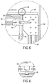
FIG. 5 is an enlarged view of a portion of the positioning table assembly ofFIG. 4 . -
FIG. 6 is an enlarged view of a portion of the positioning table assembly ofFIG. 4 . -
FIG. 7 is a front elevational view of a table bed of the positioning table assembly ofFIGS. 3 and 4 . -
FIG. 8 is a top plan view of a table bed of the positioning table assembly ofFIGS. 3 and 4 . -
FIG. 9 is a side elevational view of a table bed of the positioning table assembly ofFIGS. 3 and 4 . -
FIG. 10 is a top plan view of a table top of the positioning table assembly ofFIGS. 3 and 4 . -
FIG. 11 is a side elevational view of a table top of the positioning table assembly ofFIGS. 3 and 4 . -
FIG. 12 is a bottom plan view of a table top of the positioning table assembly ofFIGS. 3 and 4 . -
FIG. 13 is a sectional view taken along line 13-13 ofFIG. 12 . -
FIG. 14 is a top plan view of the positioning table assembly ofFIGS. 3 and 4 illustrating a first operational position and a second operational position. - Referring to the drawings and in particular
FIGS. 1 and2 , one embodiment of a positioning table assembly, according to the present invention, is shown at 10 for a crash test dummy, generally indicated at 12. In the embodiment illustrated, thecrash test dummy 12 is of a 10.5 year old child and is illustrated in a sitting position on thepositioning table assembly 12. Thiscrash test dummy 12 is used primarily to test the performance of automotive interiors and restraint systems for front and rear seat occupants. The size and weight of thecrash test dummy 12 are based on anthropometric studies, which are typically done separately by the following organizations, University of Michigan Transportation Research Institute (UMTRI), U.S. Military Anthropometry Survey (ANSUR), and Civilian American and European Surface Anthropometry Resource (CESAR). It should be appreciated that ranges of motions, centers of gravity, and segment masses simulate those of human subjects defined by the anthropometric data. - As illustrated in
FIGS. 3 and 4 , thecrash test dummy 12 generally includes ahead assembly 14, aspine assembly 16 having an upper end mounted to thehead assembly 14 and a lower end extending into a torso area of thecrash test dummy 12. The torso area of thecrash test dummy 12 also includes arib cage assembly 18 connected to thespine assembly 16 and a pair of arm assemblies (not shown) for a right arm assembly and a left arm assembly. Thecrash test dummy 12 includes apelvis assembly 20 and a pair of leg assemblies (only one shown) connected to thepelvis assembly 20 for aright leg assembly 22 and a left leg assembly (not shown). It should be appreciated that various components of thecrash test dummy 12 may be covered in a polyvinyl skin such as a flesh and skin assembly (not shown) for biofidelity of thecrash test dummy 12. - Referring to
FIGS. 1 through 4 , thepositioning table assembly 10 includes a table bed, generally indicated at 24, and a table top, generally indicated at 26, to support thecrash test dummy 12. Thetable bed 24 can be moved relative to an impact table, generally indicated at 28, disposed within an impact stand, generally indicated at 29. The impact table 28 includes aframe 30 that is supported by a support surface such as a floor, amovable lift linkage 32 having a lower end connected to theframe 30, and a table 34 connected to an upper end of thelift linkage 32. The table 34 supports thepositioning table assembly 10 during impact testing of thecrash test dummy 12. The impact table 28 may be raised or lowered to raise or lower thepositioning table assembly 10. It should be appreciated that thelift linkage 32 allows the table 34 to be raised and lowered relative to theframe 30. It should be appreciated that the impact table 28 and impact stand 29 are conventional and known in the art. - Referring to
FIGS. 4 through 9 , thetable bed 24 includes a frame 35 to be attached to and detached from the impact table 28. The frame 35 include a pair ofside members 36 extending longitudinally and spaced laterally and a pair ofcross-members 38 extending laterally and spaced longitudinally. The cross-members 38 are disposed between theside members 36 and connected to each other by a suitable mechanism such as a plurality of insidegusset corner brackets 39, which are, in turn, joined to theside members 36 andcross-members 38 by a suitable mechanism such as welding, fasteners, etc. Theside members 36 andcross-members 38 form a general "H" shape. The frame 35 also includes a plurality ofleg members 40 extending vertically from ends of theside members 36. Theleg members 40 are connected to theside members 36 by a suitable mechanism such as a plurality of joiningplates 42, which are, in turn, joined to theside members 36 andleg members 40 by a suitable mechanism such as welding, fasteners, etc. The cross-members 38 may include anotch 43 extending therein for a function to be described. Themembers - The
table bed 24 also includes a plurality ofcasters 44 connected to the frame 35 to allow the frame 35 to move on the support surface and relative to the impact table 28. Thecasters 44 are of a swivel and lock caster type. Onecaster 44 is connected to the bottom of one of theleg members 40. Thecaster 44 includes abracket 46 connected to theleg member 40 by a suitable mechanism such as fasteners and aroller 48 rotatably connected to thebracket 46. It should be appreciated that thecasters 44 are conventional to allow rolling movement along a support surface. - The
table bed 24 further includes a pair ofrails 50 to allow for gross "Y" axis location setup. Therails 50 are linear and extend longitudinally and are spaced laterally. Onerail 50 is disposed on top of one of theside members 36 and connected thereto by a suitable mechanism such as welding, fasteners, etc. Thetable bed 24 also includes a plurality of bearingcarriages 52 movably cooperating with therails 50. The bearingcarriages 52 are of a linear ball bearing type. The bearingcarriages 52 are spaced longitudinally along therails 50 and are movable along therails 50. - The
positioning table assembly 10 includes one ormore clamp assemblies 54 to attach thetable bed 24 to the impact table 28. Theclamp assembly 54 includes ahook member 56 and abracket 58 attached to thehook member 56. Thehook member 56 is of a "j" hook type. Thebracket 58 slides in atrack 60 extending longitudinally along theside member 36. Theclamp assembly 54 also includes a lockinghandle 60 attached to thebracket 58 to lock thebracket 58 in place along thetrack 60. Theclamp assembly 54 further includes apull handle 64 attached to one end of thehook member 56. The pull handle 64 is of a split ring type. The operator slides theclamp assembly 54 in thetrack 60 until the hook portion of thehook member 56 is under a lip of the impact table 28, pulls up on thepull handle 64, and tightens the locking handle 60 as illustrated inFIG. 5 . It should be appreciated that theclamp assemblies 54 are adjustable for impact tables 28 of different widths. - Referring to
FIGS. 10 through 13 , thepositioning table assembly 10 also includes thetable top 26, which is disposed on top of thetable bed 24 to support thecrash test dummy 12. Thetable top 26 includes atop plate 66 that is generally circular in shape, but may be any suitable shape. Thetable top 26 also includes a bearingplate 68 that is generally circular in shape, but may be any suitable shape. The bearingplate 68 has a diameter greater than a diameter of thetop plate 66. Thetop plate 66 includes a welded edge orlip 70 about the circumference thereof to form acavity 72. Thelip 70 acts as a travel stop to limit the movement and a pinch guard to remove "pinch points" between thetop plate 66 and bearingplate 68. The bearingplate 68 is attached to the bearingcarriages 52 by a suitable mechanism such as fasteners. It should be appreciated that a pinch gap exists between thelip 70 and the bearingplate 68. It should also be appreciated that the bearingplate 68 has allowances to be attached to conventional impact tables 28. - The
table top 26 further includes a plurality of ball transfers 74 attached to the bearingplate 68 to allow for movement of thetop plate 66 linearly in the X and Y axes as well as rotationally about the Z axis. The ball transfers 74 are of a ball bearing roller guide type. The ball transfers 74 are spaced radially and diagonally along the bearingplate 68. Thetop plate 66 sits on top of the ball transfers 74 such that the ball transfers 74 are disposed in thecavity 72 of thetop plate 66. It should be appreciated that thetop plate 66 slides or shifts on the ball transfers 74 and the ball transfers 74 may be added or subtracted to change allowable shift position. It should also be appreciated that thetable top 66 has a predetermined distance of movement in the X and Y axes. It should further be appreciated that thecrash test dummy 12 is seated on top of thetop plate 66. - The
table top 26 also includes one or morepermanent electromagnets 76 to hold thetop plate 66 in place relative to the bearingplate 68. Thetable top 26 includes one ormore solenoids 78 to move theelectromagnets 76 relative to the bearingplate 68. Thesolenoids 78 are of a linear pull type solenoid and connected to a source of power (not shown). Thetable top 26 further includes a plurality ofmagnet holders 80 to hold theelectromagnets 76 and a plurality of magnetholder guide rods 82 connected to thesolenoids 78 to guide the movement of themagnet holders 80. Thetable top 26 includes one ormore springs 84 disposed between themagnet holder 80 and theelectromagnet 76. Thespring 84 is of a conical compression type. The bearingplate 68 has one ormore apertures 86 extending therethrough to allow theelectromagnets 76 andsolenoids 78 to extend therethrough. In the embodiment illustrated, the bearingplate 68 has threeapertures 86 spaced radially along a diameter thereof for the threeelectromagnets 76 andsolenoids 78, which extend through theapertures 86. It should be appreciated that thesolenoids 78 are attached to the bearingplate 68 by a suitable mechanism such as fasteners. It should be appreciated that thesolenoids 78 allow the magnets to travel a predetermined distance away from thetop plate 66 during movement. It should further be appreciated that thenotches 43 in the cross-members 38 allow for clearance of thesolenoids 78 when thetable top 26 is moved relative to thetable bed 24. - The
positioning table assembly 10 includes an internally powered external trigger switch (not shown) to initiate the "ON" time of thesolenoids 78. In one embodiment, the trigger switch is a relay. Thepositioning table assembly 10 may include an adjustable delay relay (not shown) to limit the magnet electricity "ON" time. The delay relay turns theelectromagnet 76 "OFF" for the desired time interval. The delay relay will only reset when the trigger switch resets after the time delay interval has ended, at which time, can be repeated. Thesolenoids 78 will retract theelectromagnets 76 away from thetop plate 66 to minimize the holding force and allow theelectromagnets 76 to drop out of the way when thecrash test dummy 12 is being positioned to maintain the free movement of thetop plate 66 such that thetop plate 66 moves or shifts relative to the bearingplate 68. It should be appreciated that when electricity is ON or supplied to eachsolenoid 78, theelectromagnet 76 is OFF or disengaged with thetop plate 66. It should also be appreciated that theelectromagnets 78 will hold thetop plate 66 securely when not ON or engaged. It should further be appreciated that the trigger switch and solenoids may be controlled by a foot switch (not shown) and when the foot switch is depressed, thetop plate 66 is free to move and rotate in the X-Y direction and rotate about the Z axis. It should still further be appreciated that thesprings 84 are placed under theelectromagnets 76 and the retractedelectromagnets 76 are returned to thetop plate 66 for braking force when the foot switch is released. - The
positioning table assembly 10 further includes a locatingpin 86. The locatingpin 86 is of a spring loaded type. The locatingpin 86 is connected to one of the bearingcarriages 52 to locate thetable top 26 relative to thetable bed 24. The locatingpin 86 includes anindexing plunger 88 that is spring loaded. An operator pulls down on theplunger 88 to release thetable top 26. After thetable top 26 has moved slightly, the operator releases theplunger 88 and continues to move thetable top 26 and theplunger 88 will automatically engage at the next location of therail 50, right or left, as illustrated inFIG. 6 . - Referring to
FIG. 14 , in operation, thetable bed 24 is secured to the impact table 28 in the impact stand 29. Thetable top 26 supports thecrash test dummy 12. As illustrated in phantom lines, thetable top 26 may be positioned in a first operational position for a left side impact test. As illustrated in solid lines, thetable top 26 may be positioned in a second operational position for another impact test. In addition, thetop plate 66 may be rotated about the Z axis to position thedummy 12 in yet another operational position. - The present invention has been described in an illustrative manner. It is to be understood that the terminology, which has been used, is intended to be in the nature of words of description rather than of limitation.
- Many modifications and variations of the present invention are possible in light of the above teachings. Therefore, the present invention may be practiced other than as specifically described.
Claims (14)
- A positioning table assembly for a crash test dummy (12) comprising:
a table bed (24) adapted to be attached to an impact table (28) for the crash test dummy (12); characterized by:a table top (26) adapted to support the crash test dummy (12) and movably attached to said table bed (24) for independent linear movement in X and Y axes and rotationally about a Z axis relative to the table bed (24) to position the crash test dummy (12) relative to said table bed (24);wherein said table bed (24) includes a plurality of rails (50) and a plurality of bearing carriages (52) cooperating with said table top (26) and said rails (50) and movable along said rails (50) to allow said table top (26) to move linearly along said rails (50) and relative to said table bed (24). - A positioning table assembly as set forth in any of the preceding claims wherein said table top (26) includes a bearing plate (68) and a top plate (66) moveable relative to said bearing plate (68).
- A positioning table assembly as set forth in claim 2 wherein said table top (26) includes a plurality of ball transfers (74) disposed between said bearing plate (68) and said top plate (66) to allow said top plate (66) to be moved in an X and Y direction and rotate about the Z axis relative to said bearing plate (68).
- A positioning table assembly as set forth in claim 2 including a plurality of electromagnets (76) to hold said top plate (66) top securely to said bearing plate (68) when not engaged.
- A positioning table assembly as set forth in claim 4 including a plurality of solenoids (78) surrounding said electromagnets (76) to allow said electromagnets (76) to drop out of the way when the crash test dummy (12) is being positioned.
- A positioning table assembly as set forth in claim 2 wherein said top plate (66) includes a lip (70) extending toward said bearing plate (68).
- A positioning table assembly as set forth in any of the preceding claims wherein said table bed (24) includes a frame (30) having a plurality of legs (40) extending downwardly.
- A positioning table assembly as set forth in claim 7 wherein said table bed (24) includes a plurality of casters (44) connected to said legs (40) to allow said table bed (24) to move along a support surface.
- A positioning table assembly as set forth in claim 7 including a plurality of clamp assemblies (54) adapted to attach said frame (30) to the impact table (28).
- A positioning table assembly as set forth in claim 9 wherein said clamp assemblies (54) are adjustable, and/or wherein each of said clamp assemblies (54) include a hook member (56) being generally "j" shaped.
- A positioning table assembly as set forth in claim 1 further comprising:said table bed (24) including a frame (30) and a plurality of rails (50) extending linearly along said frame (30); andsaid table top (26) having a bearing plate (68) attached to said bearing carriages (52), a top plate (66) adapted to support the crash test dummy (12), and a plurality of ball transfers (74) disposed between said top plate (66) and said bearing plate (68).
- A positioning table assembly as set forth in claim 11 including a plurality of electromagnets (76) to hold said top plate (66) top securely to said bearing plate (68) when not engaged.
- A positioning table assembly as set forth in claim 12 including a plurality of solenoids (78) surrounding said electromagnets (76) to allow said electromagnets (76) to drop out of the way when the crash test dummy (12) is being positioned.
- A positioning table assembly as set forth in any of claims 11 to 13 wherein said top plate (66) includes a lip (70) extending toward said bearing plate (68), and/or
including a plurality of casters (44) connected to said frame (30) to allow said table bed (24) to move along a support surface, and/or
including a plurality of clamp assemblies (54) adapted to attach said frame (30) to the impact table (28), and/or
wherein each of said clamp assemblies (54) include a hook member (56) being generally "j" shaped.
Applications Claiming Priority (2)
| Application Number | Priority Date | Filing Date | Title |
|---|---|---|---|
| US201462027304P | 2014-07-22 | 2014-07-22 | |
| US14/803,605 US9715838B2 (en) | 2014-07-22 | 2015-07-20 | Positioning table assembly for crash test dummy |
Publications (2)
| Publication Number | Publication Date |
|---|---|
| EP2977978A1 EP2977978A1 (en) | 2016-01-27 |
| EP2977978B1 true EP2977978B1 (en) | 2019-05-15 |
Family
ID=53783573
Family Applications (1)
| Application Number | Title | Priority Date | Filing Date |
|---|---|---|---|
| EP15177701.8A Not-in-force EP2977978B1 (en) | 2014-07-22 | 2015-07-21 | Positioning table assembly for crash test dummy |
Country Status (2)
| Country | Link |
|---|---|
| US (1) | US9715838B2 (en) |
| EP (1) | EP2977978B1 (en) |
Families Citing this family (8)
| Publication number | Priority date | Publication date | Assignee | Title |
|---|---|---|---|---|
| US20180259425A1 (en) * | 2017-03-07 | 2018-09-13 | Humanetics Innovative Solutions, Inc. | Articulating dummy positioning system for crash test dummy |
| CN107578680B (en) * | 2017-10-16 | 2019-05-17 | 牡丹江师范学院 | A kind of experimental facilities for electromagnetics teaching |
| CN112005075A (en) | 2018-01-24 | 2020-11-27 | 惠曼创新解决方案公司 | Fiber optic system for detecting forces on anthropomorphic test devices and measuring their deformations |
| CN109556978B (en) * | 2019-01-23 | 2024-03-15 | 上汽大众汽车有限公司 | Drop-out impact test equipment |
| US10876932B2 (en) | 2019-01-31 | 2020-12-29 | Toyota Motor Engineering & Manufacturing North America, Inc. | Vehicle airbag testing devices and methods of testing vehicle airbags using the same |
| WO2020172413A1 (en) | 2019-02-20 | 2020-08-27 | Humanetics Innovative Solutions, Inc. | Optical fiber system having helical core structure for detecting forces during a collision test |
| CN113692525A (en) | 2019-02-20 | 2021-11-23 | 惠曼创新解决方案公司 | Shape sensing system and method for anthropomorphic testing device |
| CN114323689B (en) * | 2021-12-28 | 2024-11-19 | 阿波罗智联(北京)科技有限公司 | Autonomous vehicle crash test structure |
Citations (2)
| Publication number | Priority date | Publication date | Assignee | Title |
|---|---|---|---|---|
| US20030219701A1 (en) * | 2000-05-12 | 2003-11-27 | Zeier Bruce E. | Simulator for aircraft flight training |
| GB2474279A (en) * | 2009-10-09 | 2011-04-13 | Ansible Motion Ltd | Motion platform for vehicle simulator |
Family Cites Families (9)
| Publication number | Priority date | Publication date | Assignee | Title |
|---|---|---|---|---|
| US2188053A (en) * | 1937-08-23 | 1940-01-23 | Curtis Companies Inc | Assembling device |
| JPH01242989A (en) * | 1988-03-24 | 1989-09-27 | Kazuya Hirose | Longitudinal and lateral moving and swiveling mechanism for table |
| JPH08190430A (en) * | 1995-01-12 | 1996-07-23 | Matsushita Electric Ind Co Ltd | Positioning table |
| EP1216787B1 (en) * | 2000-12-21 | 2004-08-18 | Liechti Engineering AG | Positioning device |
| KR100569008B1 (en) | 2003-09-25 | 2006-04-07 | 현대자동차주식회사 | Arm assembly of crash test dummy |
| US8407033B2 (en) | 2009-06-23 | 2013-03-26 | Humanetics Innovative Solutions, Inc. | System for modeling dynamic response changes in an anthropomorphic dummy |
| FR2966966B1 (en) | 2010-10-28 | 2012-10-26 | Peugeot Citroen Automobiles Sa | POSITIONING TOOL FOR FASTENING ON THE HEAD OF A MANNEQUIN PLACED IN THE INTERIOR OF A MOTOR VEHICLE AND MANNEQUIN COMPRISING SUCH A TOOL |
| US8823477B2 (en) * | 2011-06-21 | 2014-09-02 | They Innovate Inc. | Shielded magnetic attachment apparatus |
| US9355575B2 (en) | 2012-06-12 | 2016-05-31 | Humanetics Innovative Solutions, Inc. | Chest band assembly for crash test dummy |
-
2015
- 2015-07-20 US US14/803,605 patent/US9715838B2/en not_active Expired - Fee Related
- 2015-07-21 EP EP15177701.8A patent/EP2977978B1/en not_active Not-in-force
Patent Citations (2)
| Publication number | Priority date | Publication date | Assignee | Title |
|---|---|---|---|---|
| US20030219701A1 (en) * | 2000-05-12 | 2003-11-27 | Zeier Bruce E. | Simulator for aircraft flight training |
| GB2474279A (en) * | 2009-10-09 | 2011-04-13 | Ansible Motion Ltd | Motion platform for vehicle simulator |
Also Published As
| Publication number | Publication date |
|---|---|
| EP2977978A1 (en) | 2016-01-27 |
| US9715838B2 (en) | 2017-07-25 |
| US20160027343A1 (en) | 2016-01-28 |
Similar Documents
| Publication | Publication Date | Title |
|---|---|---|
| US9715838B2 (en) | Positioning table assembly for crash test dummy | |
| CN101786430B (en) | Child vehicle seat | |
| US9916775B2 (en) | Joint assembly for crash test dummy | |
| US11872167B2 (en) | Mobility device securement system | |
| CN107031477B (en) | Integrated power thigh stretcher | |
| EP3626619B1 (en) | Multi-stage seatback extension system | |
| US20120258810A1 (en) | Lateral dynamic simulation device | |
| CN111660894A (en) | Retaining device for a vehicle seat | |
| US8297698B2 (en) | Mechatronic vehicle safety seat | |
| CA2936872C (en) | Safety seat/booster seat harness pad | |
| US20190001849A1 (en) | Seat Back With Pivotable Armrest and Armrest Restrictor | |
| CN112829708B (en) | Wheelchair passenger restraint structure | |
| KR20170037222A (en) | Caster Apparatus having Deceleration device | |
| JP2025175025A (en) | Support bar mounting system for ride vehicles and method for minimum closure indication - Patents.com | |
| CN202869390U (en) | Universal seat checking fixture | |
| BR202015000435Y1 (en) | vehicle seat item retention device | |
| EP2510989B1 (en) | Lateral dynamic simulation device | |
| CN113271816A (en) | Seat base plate | |
| EP3372978A1 (en) | Articulating dummy positioning system for crash test dummy | |
| CN106965724B (en) | Mechanical and manual leg tilting device | |
| US20170050661A1 (en) | Multi-function baby carriage | |
| EP3216504A3 (en) | Attraction for amusement rides with improved support construction | |
| KR20160124798A (en) | Head restraint system for vehicles | |
| EP3188930B1 (en) | Head rest for absorbing of an eccentric collision of a car | |
| CN213275962U (en) | Vehicle-mounted height limit detection device |
Legal Events
| Date | Code | Title | Description |
|---|---|---|---|
| PUAI | Public reference made under article 153(3) epc to a published international application that has entered the european phase |
Free format text: ORIGINAL CODE: 0009012 |
|
| AK | Designated contracting states |
Kind code of ref document: A1 Designated state(s): AL AT BE BG CH CY CZ DE DK EE ES FI FR GB GR HR HU IE IS IT LI LT LU LV MC MK MT NL NO PL PT RO RS SE SI SK SM TR |
|
| AX | Request for extension of the european patent |
Extension state: BA ME |
|
| 17P | Request for examination filed |
Effective date: 20160726 |
|
| RBV | Designated contracting states (corrected) |
Designated state(s): AL AT BE BG CH CY CZ DE DK EE ES FI FR GB GR HR HU IE IS IT LI LT LU LV MC MK MT NL NO PL PT RO RS SE SI SK SM TR |
|
| STAA | Information on the status of an ep patent application or granted ep patent |
Free format text: STATUS: EXAMINATION IS IN PROGRESS |
|
| 17Q | First examination report despatched |
Effective date: 20171222 |
|
| REG | Reference to a national code |
Ref country code: DE Ref legal event code: R079 Ref document number: 602015030237 Country of ref document: DE Free format text: PREVIOUS MAIN CLASS: G09B0023320000 Ipc: G09B0023300000 |
|
| GRAP | Despatch of communication of intention to grant a patent |
Free format text: ORIGINAL CODE: EPIDOSNIGR1 |
|
| STAA | Information on the status of an ep patent application or granted ep patent |
Free format text: STATUS: GRANT OF PATENT IS INTENDED |
|
| RIC1 | Information provided on ipc code assigned before grant |
Ipc: G09B 23/32 20060101ALI20181115BHEP Ipc: G09B 23/30 20060101AFI20181115BHEP |
|
| INTG | Intention to grant announced |
Effective date: 20181205 |
|
| GRAS | Grant fee paid |
Free format text: ORIGINAL CODE: EPIDOSNIGR3 |
|
| GRAA | (expected) grant |
Free format text: ORIGINAL CODE: 0009210 |
|
| STAA | Information on the status of an ep patent application or granted ep patent |
Free format text: STATUS: THE PATENT HAS BEEN GRANTED |
|
| AK | Designated contracting states |
Kind code of ref document: B1 Designated state(s): AL AT BE BG CH CY CZ DE DK EE ES FI FR GB GR HR HU IE IS IT LI LT LU LV MC MK MT NL NO PL PT RO RS SE SI SK SM TR |
|
| REG | Reference to a national code |
Ref country code: CH Ref legal event code: EP |
|
| REG | Reference to a national code |
Ref country code: IE Ref legal event code: FG4D |
|
| REG | Reference to a national code |
Ref country code: DE Ref legal event code: R096 Ref document number: 602015030237 Country of ref document: DE |
|
| REG | Reference to a national code |
Ref country code: NL Ref legal event code: MP Effective date: 20190515 |
|
| REG | Reference to a national code |
Ref country code: LT Ref legal event code: MG4D |
|
| PG25 | Lapsed in a contracting state [announced via postgrant information from national office to epo] |
Ref country code: NL Free format text: LAPSE BECAUSE OF FAILURE TO SUBMIT A TRANSLATION OF THE DESCRIPTION OR TO PAY THE FEE WITHIN THE PRESCRIBED TIME-LIMIT Effective date: 20190515 Ref country code: SE Free format text: LAPSE BECAUSE OF FAILURE TO SUBMIT A TRANSLATION OF THE DESCRIPTION OR TO PAY THE FEE WITHIN THE PRESCRIBED TIME-LIMIT Effective date: 20190515 Ref country code: ES Free format text: LAPSE BECAUSE OF FAILURE TO SUBMIT A TRANSLATION OF THE DESCRIPTION OR TO PAY THE FEE WITHIN THE PRESCRIBED TIME-LIMIT Effective date: 20190515 Ref country code: LT Free format text: LAPSE BECAUSE OF FAILURE TO SUBMIT A TRANSLATION OF THE DESCRIPTION OR TO PAY THE FEE WITHIN THE PRESCRIBED TIME-LIMIT Effective date: 20190515 Ref country code: FI Free format text: LAPSE BECAUSE OF FAILURE TO SUBMIT A TRANSLATION OF THE DESCRIPTION OR TO PAY THE FEE WITHIN THE PRESCRIBED TIME-LIMIT Effective date: 20190515 Ref country code: AL Free format text: LAPSE BECAUSE OF FAILURE TO SUBMIT A TRANSLATION OF THE DESCRIPTION OR TO PAY THE FEE WITHIN THE PRESCRIBED TIME-LIMIT Effective date: 20190515 Ref country code: PT Free format text: LAPSE BECAUSE OF FAILURE TO SUBMIT A TRANSLATION OF THE DESCRIPTION OR TO PAY THE FEE WITHIN THE PRESCRIBED TIME-LIMIT Effective date: 20190915 Ref country code: HR Free format text: LAPSE BECAUSE OF FAILURE TO SUBMIT A TRANSLATION OF THE DESCRIPTION OR TO PAY THE FEE WITHIN THE PRESCRIBED TIME-LIMIT Effective date: 20190515 Ref country code: NO Free format text: LAPSE BECAUSE OF FAILURE TO SUBMIT A TRANSLATION OF THE DESCRIPTION OR TO PAY THE FEE WITHIN THE PRESCRIBED TIME-LIMIT Effective date: 20190815 |
|
| PG25 | Lapsed in a contracting state [announced via postgrant information from national office to epo] |
Ref country code: GR Free format text: LAPSE BECAUSE OF FAILURE TO SUBMIT A TRANSLATION OF THE DESCRIPTION OR TO PAY THE FEE WITHIN THE PRESCRIBED TIME-LIMIT Effective date: 20190816 Ref country code: LV Free format text: LAPSE BECAUSE OF FAILURE TO SUBMIT A TRANSLATION OF THE DESCRIPTION OR TO PAY THE FEE WITHIN THE PRESCRIBED TIME-LIMIT Effective date: 20190515 Ref country code: BG Free format text: LAPSE BECAUSE OF FAILURE TO SUBMIT A TRANSLATION OF THE DESCRIPTION OR TO PAY THE FEE WITHIN THE PRESCRIBED TIME-LIMIT Effective date: 20190815 Ref country code: RS Free format text: LAPSE BECAUSE OF FAILURE TO SUBMIT A TRANSLATION OF THE DESCRIPTION OR TO PAY THE FEE WITHIN THE PRESCRIBED TIME-LIMIT Effective date: 20190515 |
|
| REG | Reference to a national code |
Ref country code: AT Ref legal event code: MK05 Ref document number: 1134350 Country of ref document: AT Kind code of ref document: T Effective date: 20190515 |
|
| PG25 | Lapsed in a contracting state [announced via postgrant information from national office to epo] |
Ref country code: AT Free format text: LAPSE BECAUSE OF FAILURE TO SUBMIT A TRANSLATION OF THE DESCRIPTION OR TO PAY THE FEE WITHIN THE PRESCRIBED TIME-LIMIT Effective date: 20190515 Ref country code: DK Free format text: LAPSE BECAUSE OF FAILURE TO SUBMIT A TRANSLATION OF THE DESCRIPTION OR TO PAY THE FEE WITHIN THE PRESCRIBED TIME-LIMIT Effective date: 20190515 Ref country code: EE Free format text: LAPSE BECAUSE OF FAILURE TO SUBMIT A TRANSLATION OF THE DESCRIPTION OR TO PAY THE FEE WITHIN THE PRESCRIBED TIME-LIMIT Effective date: 20190515 Ref country code: RO Free format text: LAPSE BECAUSE OF FAILURE TO SUBMIT A TRANSLATION OF THE DESCRIPTION OR TO PAY THE FEE WITHIN THE PRESCRIBED TIME-LIMIT Effective date: 20190515 Ref country code: CZ Free format text: LAPSE BECAUSE OF FAILURE TO SUBMIT A TRANSLATION OF THE DESCRIPTION OR TO PAY THE FEE WITHIN THE PRESCRIBED TIME-LIMIT Effective date: 20190515 Ref country code: SK Free format text: LAPSE BECAUSE OF FAILURE TO SUBMIT A TRANSLATION OF THE DESCRIPTION OR TO PAY THE FEE WITHIN THE PRESCRIBED TIME-LIMIT Effective date: 20190515 |
|
| REG | Reference to a national code |
Ref country code: DE Ref legal event code: R119 Ref document number: 602015030237 Country of ref document: DE |
|
| PG25 | Lapsed in a contracting state [announced via postgrant information from national office to epo] |
Ref country code: SM Free format text: LAPSE BECAUSE OF FAILURE TO SUBMIT A TRANSLATION OF THE DESCRIPTION OR TO PAY THE FEE WITHIN THE PRESCRIBED TIME-LIMIT Effective date: 20190515 Ref country code: IT Free format text: LAPSE BECAUSE OF FAILURE TO SUBMIT A TRANSLATION OF THE DESCRIPTION OR TO PAY THE FEE WITHIN THE PRESCRIBED TIME-LIMIT Effective date: 20190515 Ref country code: MC Free format text: LAPSE BECAUSE OF FAILURE TO SUBMIT A TRANSLATION OF THE DESCRIPTION OR TO PAY THE FEE WITHIN THE PRESCRIBED TIME-LIMIT Effective date: 20190515 |
|
| REG | Reference to a national code |
Ref country code: CH Ref legal event code: PL |
|
| PLBE | No opposition filed within time limit |
Free format text: ORIGINAL CODE: 0009261 |
|
| STAA | Information on the status of an ep patent application or granted ep patent |
Free format text: STATUS: NO OPPOSITION FILED WITHIN TIME LIMIT |
|
| PG25 | Lapsed in a contracting state [announced via postgrant information from national office to epo] |
Ref country code: TR Free format text: LAPSE BECAUSE OF FAILURE TO SUBMIT A TRANSLATION OF THE DESCRIPTION OR TO PAY THE FEE WITHIN THE PRESCRIBED TIME-LIMIT Effective date: 20190515 |
|
| REG | Reference to a national code |
Ref country code: BE Ref legal event code: MM Effective date: 20190731 |
|
| 26N | No opposition filed |
Effective date: 20200218 |
|
| GBPC | Gb: european patent ceased through non-payment of renewal fee |
Effective date: 20190815 |
|
| PG25 | Lapsed in a contracting state [announced via postgrant information from national office to epo] |
Ref country code: DE Free format text: LAPSE BECAUSE OF NON-PAYMENT OF DUE FEES Effective date: 20200201 Ref country code: PL Free format text: LAPSE BECAUSE OF FAILURE TO SUBMIT A TRANSLATION OF THE DESCRIPTION OR TO PAY THE FEE WITHIN THE PRESCRIBED TIME-LIMIT Effective date: 20190515 |
|
| PG25 | Lapsed in a contracting state [announced via postgrant information from national office to epo] |
Ref country code: LU Free format text: LAPSE BECAUSE OF NON-PAYMENT OF DUE FEES Effective date: 20190721 Ref country code: CH Free format text: LAPSE BECAUSE OF NON-PAYMENT OF DUE FEES Effective date: 20190731 Ref country code: LI Free format text: LAPSE BECAUSE OF NON-PAYMENT OF DUE FEES Effective date: 20190731 Ref country code: SI Free format text: LAPSE BECAUSE OF FAILURE TO SUBMIT A TRANSLATION OF THE DESCRIPTION OR TO PAY THE FEE WITHIN THE PRESCRIBED TIME-LIMIT Effective date: 20190515 Ref country code: BE Free format text: LAPSE BECAUSE OF NON-PAYMENT OF DUE FEES Effective date: 20190731 |
|
| PG25 | Lapsed in a contracting state [announced via postgrant information from national office to epo] |
Ref country code: FR Free format text: LAPSE BECAUSE OF NON-PAYMENT OF DUE FEES Effective date: 20190731 |
|
| PG25 | Lapsed in a contracting state [announced via postgrant information from national office to epo] |
Ref country code: IE Free format text: LAPSE BECAUSE OF NON-PAYMENT OF DUE FEES Effective date: 20190721 |
|
| PG25 | Lapsed in a contracting state [announced via postgrant information from national office to epo] |
Ref country code: GB Free format text: LAPSE BECAUSE OF NON-PAYMENT OF DUE FEES Effective date: 20190815 |
|
| PG25 | Lapsed in a contracting state [announced via postgrant information from national office to epo] |
Ref country code: CY Free format text: LAPSE BECAUSE OF FAILURE TO SUBMIT A TRANSLATION OF THE DESCRIPTION OR TO PAY THE FEE WITHIN THE PRESCRIBED TIME-LIMIT Effective date: 20190515 |
|
| PG25 | Lapsed in a contracting state [announced via postgrant information from national office to epo] |
Ref country code: IS Free format text: LAPSE BECAUSE OF FAILURE TO SUBMIT A TRANSLATION OF THE DESCRIPTION OR TO PAY THE FEE WITHIN THE PRESCRIBED TIME-LIMIT Effective date: 20190915 |
|
| PG25 | Lapsed in a contracting state [announced via postgrant information from national office to epo] |
Ref country code: MT Free format text: LAPSE BECAUSE OF FAILURE TO SUBMIT A TRANSLATION OF THE DESCRIPTION OR TO PAY THE FEE WITHIN THE PRESCRIBED TIME-LIMIT Effective date: 20190515 Ref country code: HU Free format text: LAPSE BECAUSE OF FAILURE TO SUBMIT A TRANSLATION OF THE DESCRIPTION OR TO PAY THE FEE WITHIN THE PRESCRIBED TIME-LIMIT; INVALID AB INITIO Effective date: 20150721 |
|
| PG25 | Lapsed in a contracting state [announced via postgrant information from national office to epo] |
Ref country code: MK Free format text: LAPSE BECAUSE OF FAILURE TO SUBMIT A TRANSLATION OF THE DESCRIPTION OR TO PAY THE FEE WITHIN THE PRESCRIBED TIME-LIMIT Effective date: 20190515 |