EP2977757A1 - Disposable chamber for analyzing biologic fluids - Google Patents
Disposable chamber for analyzing biologic fluids Download PDFInfo
- Publication number
- EP2977757A1 EP2977757A1 EP15178645.6A EP15178645A EP2977757A1 EP 2977757 A1 EP2977757 A1 EP 2977757A1 EP 15178645 A EP15178645 A EP 15178645A EP 2977757 A1 EP2977757 A1 EP 2977757A1
- Authority
- EP
- European Patent Office
- Prior art keywords
- planar member
- planar
- separators
- chamber
- height
- Prior art date
- Legal status (The legal status is an assumption and is not a legal conclusion. Google has not performed a legal analysis and makes no representation as to the accuracy of the status listed.)
- Granted
Links
Images


Classifications
-
- G—PHYSICS
- G01—MEASURING; TESTING
- G01N—INVESTIGATING OR ANALYSING MATERIALS BY DETERMINING THEIR CHEMICAL OR PHYSICAL PROPERTIES
- G01N33/00—Investigating or analysing materials by specific methods not covered by groups G01N1/00 - G01N31/00
- G01N33/48—Biological material, e.g. blood, urine; Haemocytometers
- G01N33/483—Physical analysis of biological material
- G01N33/487—Physical analysis of biological material of liquid biological material
- G01N33/4875—Details of handling test elements, e.g. dispensing or storage, not specific to a particular test method
- G01N33/48764—Test tape taken off a spool
-
- B—PERFORMING OPERATIONS; TRANSPORTING
- B01—PHYSICAL OR CHEMICAL PROCESSES OR APPARATUS IN GENERAL
- B01L—CHEMICAL OR PHYSICAL LABORATORY APPARATUS FOR GENERAL USE
- B01L3/00—Containers or dishes for laboratory use, e.g. laboratory glassware; Droppers
- B01L3/50—Containers for the purpose of retaining a material to be analysed, e.g. test tubes
- B01L3/502—Containers for the purpose of retaining a material to be analysed, e.g. test tubes with fluid transport, e.g. in multi-compartment structures
- B01L3/5027—Containers for the purpose of retaining a material to be analysed, e.g. test tubes with fluid transport, e.g. in multi-compartment structures by integrated microfluidic structures, i.e. dimensions of channels and chambers are such that surface tension forces are important, e.g. lab-on-a-chip
- B01L3/502738—Containers for the purpose of retaining a material to be analysed, e.g. test tubes with fluid transport, e.g. in multi-compartment structures by integrated microfluidic structures, i.e. dimensions of channels and chambers are such that surface tension forces are important, e.g. lab-on-a-chip characterised by integrated valves
-
- G—PHYSICS
- G01—MEASURING; TESTING
- G01N—INVESTIGATING OR ANALYSING MATERIALS BY DETERMINING THEIR CHEMICAL OR PHYSICAL PROPERTIES
- G01N1/00—Sampling; Preparing specimens for investigation
- G01N1/28—Preparing specimens for investigation including physical details of (bio-)chemical methods covered elsewhere, e.g. G01N33/50, C12Q
- G01N1/2813—Producing thin layers of samples on a substrate, e.g. smearing, spinning-on
-
- G—PHYSICS
- G01—MEASURING; TESTING
- G01N—INVESTIGATING OR ANALYSING MATERIALS BY DETERMINING THEIR CHEMICAL OR PHYSICAL PROPERTIES
- G01N1/00—Sampling; Preparing specimens for investigation
- G01N1/28—Preparing specimens for investigation including physical details of (bio-)chemical methods covered elsewhere, e.g. G01N33/50, C12Q
- G01N1/36—Embedding or analogous mounting of samples
-
- G—PHYSICS
- G01—MEASURING; TESTING
- G01N—INVESTIGATING OR ANALYSING MATERIALS BY DETERMINING THEIR CHEMICAL OR PHYSICAL PROPERTIES
- G01N21/00—Investigating or analysing materials by the use of optical means, i.e. using sub-millimetre waves, infrared, visible or ultraviolet light
- G01N21/01—Arrangements or apparatus for facilitating the optical investigation
- G01N21/03—Cuvette constructions
-
- G—PHYSICS
- G01—MEASURING; TESTING
- G01N—INVESTIGATING OR ANALYSING MATERIALS BY DETERMINING THEIR CHEMICAL OR PHYSICAL PROPERTIES
- G01N33/00—Investigating or analysing materials by specific methods not covered by groups G01N1/00 - G01N31/00
- G01N33/48—Biological material, e.g. blood, urine; Haemocytometers
- G01N33/483—Physical analysis of biological material
- G01N33/487—Physical analysis of biological material of liquid biological material
- G01N33/49—Blood
- G01N33/492—Determining multiple analytes
-
- G—PHYSICS
- G02—OPTICS
- G02B—OPTICAL ELEMENTS, SYSTEMS OR APPARATUS
- G02B21/00—Microscopes
- G02B21/34—Microscope slides, e.g. mounting specimens on microscope slides
-
- B—PERFORMING OPERATIONS; TRANSPORTING
- B01—PHYSICAL OR CHEMICAL PROCESSES OR APPARATUS IN GENERAL
- B01L—CHEMICAL OR PHYSICAL LABORATORY APPARATUS FOR GENERAL USE
- B01L2200/00—Solutions for specific problems relating to chemical or physical laboratory apparatus
- B01L2200/02—Adapting objects or devices to another
- B01L2200/025—Align devices or objects to ensure defined positions relative to each other
-
- B—PERFORMING OPERATIONS; TRANSPORTING
- B01—PHYSICAL OR CHEMICAL PROCESSES OR APPARATUS IN GENERAL
- B01L—CHEMICAL OR PHYSICAL LABORATORY APPARATUS FOR GENERAL USE
- B01L2200/00—Solutions for specific problems relating to chemical or physical laboratory apparatus
- B01L2200/12—Specific details about manufacturing devices
-
- B—PERFORMING OPERATIONS; TRANSPORTING
- B01—PHYSICAL OR CHEMICAL PROCESSES OR APPARATUS IN GENERAL
- B01L—CHEMICAL OR PHYSICAL LABORATORY APPARATUS FOR GENERAL USE
- B01L2300/00—Additional constructional details
- B01L2300/08—Geometry, shape and general structure
- B01L2300/0861—Configuration of multiple channels and/or chambers in a single devices
- B01L2300/0877—Flow chambers
-
- B—PERFORMING OPERATIONS; TRANSPORTING
- B01—PHYSICAL OR CHEMICAL PROCESSES OR APPARATUS IN GENERAL
- B01L—CHEMICAL OR PHYSICAL LABORATORY APPARATUS FOR GENERAL USE
- B01L2300/00—Additional constructional details
- B01L2300/08—Geometry, shape and general structure
- B01L2300/0887—Laminated structure
-
- B—PERFORMING OPERATIONS; TRANSPORTING
- B01—PHYSICAL OR CHEMICAL PROCESSES OR APPARATUS IN GENERAL
- B01L—CHEMICAL OR PHYSICAL LABORATORY APPARATUS FOR GENERAL USE
- B01L2400/00—Moving or stopping fluids
- B01L2400/04—Moving fluids with specific forces or mechanical means
- B01L2400/0403—Moving fluids with specific forces or mechanical means specific forces
- B01L2400/0406—Moving fluids with specific forces or mechanical means specific forces capillary forces
-
- G—PHYSICS
- G01—MEASURING; TESTING
- G01N—INVESTIGATING OR ANALYSING MATERIALS BY DETERMINING THEIR CHEMICAL OR PHYSICAL PROPERTIES
- G01N1/00—Sampling; Preparing specimens for investigation
- G01N1/28—Preparing specimens for investigation including physical details of (bio-)chemical methods covered elsewhere, e.g. G01N33/50, C12Q
- G01N1/30—Staining; Impregnating ; Fixation; Dehydration; Multistep processes for preparing samples of tissue, cell or nucleic acid material and the like for analysis
- G01N1/31—Apparatus therefor
- G01N1/312—Apparatus therefor for samples mounted on planar substrates
-
- G—PHYSICS
- G01—MEASURING; TESTING
- G01N—INVESTIGATING OR ANALYSING MATERIALS BY DETERMINING THEIR CHEMICAL OR PHYSICAL PROPERTIES
- G01N15/00—Investigating characteristics of particles; Investigating permeability, pore-volume or surface-area of porous materials
- G01N15/01—Investigating characteristics of particles; Investigating permeability, pore-volume or surface-area of porous materials specially adapted for biological cells, e.g. blood cells
- G01N2015/016—White blood cells
-
- G—PHYSICS
- G01—MEASURING; TESTING
- G01N—INVESTIGATING OR ANALYSING MATERIALS BY DETERMINING THEIR CHEMICAL OR PHYSICAL PROPERTIES
- G01N15/00—Investigating characteristics of particles; Investigating permeability, pore-volume or surface-area of porous materials
- G01N15/10—Investigating individual particles
- G01N2015/1006—Investigating individual particles for cytology
-
- G—PHYSICS
- G01—MEASURING; TESTING
- G01N—INVESTIGATING OR ANALYSING MATERIALS BY DETERMINING THEIR CHEMICAL OR PHYSICAL PROPERTIES
- G01N15/00—Investigating characteristics of particles; Investigating permeability, pore-volume or surface-area of porous materials
- G01N15/10—Investigating individual particles
- G01N15/14—Optical investigation techniques, e.g. flow cytometry
- G01N2015/1486—Counting the particles
-
- G—PHYSICS
- G01—MEASURING; TESTING
- G01N—INVESTIGATING OR ANALYSING MATERIALS BY DETERMINING THEIR CHEMICAL OR PHYSICAL PROPERTIES
- G01N21/00—Investigating or analysing materials by the use of optical means, i.e. using sub-millimetre waves, infrared, visible or ultraviolet light
- G01N21/01—Arrangements or apparatus for facilitating the optical investigation
- G01N21/03—Cuvette constructions
- G01N2021/0346—Capillary cells; Microcells
-
- G—PHYSICS
- G01—MEASURING; TESTING
- G01N—INVESTIGATING OR ANALYSING MATERIALS BY DETERMINING THEIR CHEMICAL OR PHYSICAL PROPERTIES
- G01N21/00—Investigating or analysing materials by the use of optical means, i.e. using sub-millimetre waves, infrared, visible or ultraviolet light
- G01N21/01—Arrangements or apparatus for facilitating the optical investigation
- G01N21/03—Cuvette constructions
- G01N2021/0364—Cuvette constructions flexible, compressible
-
- G—PHYSICS
- G01—MEASURING; TESTING
- G01N—INVESTIGATING OR ANALYSING MATERIALS BY DETERMINING THEIR CHEMICAL OR PHYSICAL PROPERTIES
- G01N35/00—Automatic analysis not limited to methods or materials provided for in any single one of groups G01N1/00 - G01N33/00; Handling materials therefor
- G01N35/00009—Automatic analysis not limited to methods or materials provided for in any single one of groups G01N1/00 - G01N33/00; Handling materials therefor provided with a sample supporting tape, e.g. with absorbent zones
-
- Y—GENERAL TAGGING OF NEW TECHNOLOGICAL DEVELOPMENTS; GENERAL TAGGING OF CROSS-SECTIONAL TECHNOLOGIES SPANNING OVER SEVERAL SECTIONS OF THE IPC; TECHNICAL SUBJECTS COVERED BY FORMER USPC CROSS-REFERENCE ART COLLECTIONS [XRACs] AND DIGESTS
- Y10—TECHNICAL SUBJECTS COVERED BY FORMER USPC
- Y10T—TECHNICAL SUBJECTS COVERED BY FORMER US CLASSIFICATION
- Y10T436/00—Chemistry: analytical and immunological testing
- Y10T436/10—Composition for standardization, calibration, simulation, stabilization, preparation or preservation; processes of use in preparation for chemical testing
- Y10T436/101666—Particle count or volume standard or control [e.g., platelet count standards, etc.]
-
- Y—GENERAL TAGGING OF NEW TECHNOLOGICAL DEVELOPMENTS; GENERAL TAGGING OF CROSS-SECTIONAL TECHNOLOGIES SPANNING OVER SEVERAL SECTIONS OF THE IPC; TECHNICAL SUBJECTS COVERED BY FORMER USPC CROSS-REFERENCE ART COLLECTIONS [XRACs] AND DIGESTS
- Y10—TECHNICAL SUBJECTS COVERED BY FORMER USPC
- Y10T—TECHNICAL SUBJECTS COVERED BY FORMER US CLASSIFICATION
- Y10T436/00—Chemistry: analytical and immunological testing
- Y10T436/25—Chemistry: analytical and immunological testing including sample preparation
- Y10T436/25375—Liberation or purification of sample or separation of material from a sample [e.g., filtering, centrifuging, etc.]
Definitions
- the present invention relates to chambers for analyzing biologic fluids in general, and to chambers that permit the enumeration of particulate matter within the biologic fluid in particular.
- the classic method of enumerating particles in a liquid medium is the hemocytometer, which includes a chamber manufactured to a precise height and having visible ruled areas of precise dimension.
- the liquid containing the particles to be enumerated is introduced into the chamber.
- the liquid is diluted if necessary to reduce the number of particles to a manageable number.
- the operator then counts the number of particles in a given demarcated area. Since the area and height of the chamber are precisely known, the particle count per volume can be calculated.
- these chambers are generally ruled to demarcate a known area, this is not necessary if such a chamber is used in an image analyzer. With an image analyzer, rulings on the chamber itself are unnecessary because the field of view can be exactly calculated from the image.
- hemocytometer chambers are relatively expensive and were not considered disposable.
- Modem precision plastics molding techniques have allowed the manufacture of some types of hemocytometer chambers at sufficiently low cost so as to be considered disposable in some instances, but chambers requiring substantial precision and/or thicknesses less than the traditional 0.1 mm are very difficult to mold accurately.
- U.S. Patent No. 4,950,455 describes a counting chamber formed from a rigid glass slide and a rigid glass coverslip with rigid particles, such as glass beads, contained therebetween. The beads maintain a thin spacing between the slide and coverslip, thereby forming the counting chamber.
- a counting chamber formed from rigid upper and lower panels separated by rigid particles has substantial limitations, however.
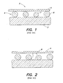
- a prior art assembly generally denoted by 2 consists of a lower glass slide 3, an upper glass coverslip 4 and an entrapped layer formed from a plurality of glass beads 5. Because any microscopic beads are not completely uniform, having a coefficient of variation of the diameter of up to 10% or greater, the larger beads 6 "prop-up" the coverslip 4 to some extent, and the smaller beads 7 have no effect on the separation. The differences in bead diameter is a problem because while it is easy to determine and/or control the mean diameter of the beads, the spread of diameters is less well controlled, rendering the system less accurate than is desired.
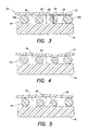
- a greater problem is the presence of particulate debris as shown in FIG. 2 .
- This debris can be present when the chamber is made or can be introduced by the environment or from a sample.
- the debris 8 can "prop up" the coverslip 4 and create a large area of increased volume in the chamber, which destroys its accuracy.
- Another issue with this type of prior art chamber is that it is difficult to package a plurality of such disposables in an instrument used for automatically scanning and counting particles, such as an image analyzing system.
- What is needed is an apparatus and method to overcome the limitations of the prior art, that provides a chamber for analyzing biologic fluids, including the enumeration of particulates within the fluid, which is inexpensive to produce, relatively insensitive to trapped particulate debris, and amenable to packaging for use in an automated test system.
- an apparatus for analyzing biologic fluid comprising:
- an apparatus for analyzing biologic fluid comprising:
- the at least one chamber includes a port.
- an apparatus for analyzing biologic fluid includes a first planar member, a second planar member, and at least three separators. At least one of planar members is transparent. The separators are disposed between the members, and separate the members to form a chamber having a height. At least one of the members or separators is sufficiently flexible to permit the chamber height to approximate the mean size of the separators.
- the biologic fluid to be analyzed is disposed within the chamber.
- At least one of the first planar member and the second planar member comprise flexible plastic. Further preferably, both of the first planar member and the second planar member comprise flexible plastic.
- the separators are flexible relative to the first planar member and second planar member.
- one of the separators, first planar member, and second planar member has a greater flexibility relative to at least one of the others of the separators, first planar member, and second planar member.
- the first planar member has a greater flexibility than the second planar member and the separators.
- the separators are attached to at least one of the first planar member or the second planar member.
- At least one of the first planar member or the second planar member comprises linked rigid elements.
- one of the first planar member or the second planar member comprises linked rigid elements and the other of the first planar member or second planar member comprises flexible plastic.
- the separators include uniformly dyed, slightly compressible plastic beads.
- the separators are projections of uniform height attached to at least one of the first planar member or second planar member.
- one of the first planar member or the second planar member comprises one or more ports.
- each planar member is a tape that can be wound on a reel.
- the planar members are initially attached to one another.
- each planar member is initially separated from the other planar member.
- a cassette having at least one source reel and at least one take-up reel.
- the planar members are initially wound on a source reel, and are transferred to a take-up reel during operation of the apparatus.
- An analysis region is disposed between the source and take-up reels. The planar members pass through the analysis region during the operation of the apparatus.
- the present invention extends to a method of enumerating the cellular or particulate constituents of a sample of whole, anticoagulated blood, comprising the steps of:
- the biologic fluid is blood.
- the method preferably further comprises the step of calculating the chamber height by measuring the average attenuation of light transmitted through the separators.
- the step of determining the volume of biologic fluid contained within the film further comprises the steps of: determining the area of the film; and calculating the volume of biologic fluid by multiplying the chamber height times the area of the film.
- the film volume is calculated by interferometric imaging of the drop of biologic fluid deposited onto the planar member prior to approximating the planar members.
- the present invention further extends to a method of enumerating the cellular or particulate constituents of a sample of whole, anticoagulated blood, comprising the steps of:
- top and bottom planar members are rigid and the separators are flexible, separators larger than the mean diameter will be compressed, and the planar members will approximate until more and more separators come into contact with the planar members, preventing further approximation. At that point, the height of the chamber approximates the average height of the separators and is readily ascertainable.
- the separators are rigid and the top planar member is flexible, the top planar member will deform and be "tented-up" in a small area around each of the larger separators and be lower over smaller separators.
- the chamber will have an average height which closely approximates average separator height.
- An advantage of the present invention is, therefore, that a chamber is formed having a volume that is accurately determinable because the height of the chamber is substantially uniform.
- Another advantage of the present invention is that it can be manufactured in an inexpensive form and still provide the desired accuracy.
- the present invention does not require accurately machined voids or separators to accurately establish volume. Consequently, the invention can be manufactured inexpensively and still provide the desired accuracy.
- the present invention can practically be offered in a disposable form.
- the present invention apparatus 10 for analyzing biologic fluid includes a first planar member 12, a second planar member 14, and at least three separators 16. At least one of planar members 12, 14 is transparent. The separators 16 are disposed between the members 12, 14, and separate the planar members 12, 14 to form a chamber 18 having a height 20. At least one of the members 12, 14 or separators 16 is sufficiently flexible to permit the chamber height 20 between the members 12, 14 to approximate the mean height of the separators 16.
- the separators 16 can be any structure that is disposable between the planar members 12, 14, operable to space the planar members 12, 14 apart from one another.
- the dimension of a separator 16 that extends between the planar members is referred to herein as the height 22 of the separator 16.
- the heights 22 of the separators 16 typically do not equal one another exactly, but are within commercially acceptable tolerance for spacing means used in similar analysis apparatus.
- Spherical beads are an example of an acceptable separator 16 and are commercially available from, for example, Bangs Laboratories of Fishers, Indiana, USA.
- the separators 16 consist of a material that has greater flexibility than one or both of the first planar member 12 and the second planar member 14; i.e., relatively speaking, one or both of the planar members 12, 14 may be considered to be rigid relative to the separators 16 and the separators 16 may be considered to be flexible relative to one or both of the planar members 12, 14.
- the separators 16 consist of a material that has less flexibility than one or both of the first planar member 12 and the second planar member 14; i.e., relatively speaking, one or both of the planar members 12, 14 may be considered to be flexible relative to the separators 16 and the separators 16 may be considered to be rigid relative to one or both of the planar members 12, 14.
- planar members 12, 14 can be made from a variety of materials, provided at least one of the planar members 12, 14 is transparent.
- Transparent plastic films consisting of acrylic or polystyrene are examples of acceptable planar members 12, 14.
- Planar members 12, 14 in the form of a tape are particularly useful because they can be easily wound on a reel.
- the first planar member 12 and the second planar member 14 are separated by a chamber 18 formed by plurality of separators 16 in the form of spherical beads.
- These beads 16 are formed from a material that has greater flexibility than the first planar member 12 and the second planar member 14; i.e., the planar members 12, 14 may be considered to be rigid relative to the beads 16 and the beads 16 may be considered to be flexible relative to the planar members 12, 14.
- Plastic beads 16 formed from polystyrene, polycarbonate, silicone and the like can be used. In this example, larger beads 16A are compressed to the point where the planar members 12, 14 have approximated to the point where most beads 16 are touching the interior surfaces 24 of the planar members 12, 14, thereby making the chamber height 20 just slightly less than the mean bead diameter.
- the first planar member 12 is formed from a material more flexible than the spherical beads 16 and the second planar member 14, and will overlay the beads 16 in a tent-like fashion, where the areas between the beads 16 are some arbitrary height determined by the bead diameters supporting that piece of the planar member 12.
- Any transparent plastic film, such as acrylic, polystyrene, or the like will work provided it is thin enough to flex as shown. It should be apparent that in this circumstance, although small local areas will deviate from the desired chamber height 20, the average height of all the tented areas will be very close to that of the mean bead diameter. Our testing indicates that that the mean chamber height can be controlled to 1% or better at chamber heights of less than four microns using the present invention.
- FIG. 5 shows the chamber 18 of FIG. 4 wherein a piece of particulate debris 26 has lodged.
- the upper planar member 12 over the debris 26 has tented up, and the area under the debris 26 is of unknown height, but this disturbance only affects a small area of the chamber 18, as opposed to what would occur if the whole system was rigid.
- FIG. 6 shows another embodiment of the invention 10, where the second planar member 14 is formed from a one inch wide strip of transparent plastic film (e.g., polyethylene terphthalate (PET)) of approximately fifty (50) microns in thickness, the first planar member 12 is formed from the same material as the second planar member 14 but in twenty-three (23) micron thickness, and the chamber 18 therebetween is formed from a plurality of plastic beads 16 with a mean diameter of four (4) microns.
- the first planar member 12 has an inner coating of a coloration agent, such as acridine orange, which will differentially color living white blood cells when examined with fluorescent illumination.
- reagents for fluorescence include astrozone orange, FITC, rhodamine and the like.
- the first planar member 12 includes a plurality of ports 28 (e.g., approximately three hundred (300) microns in diameter) punched at regular intervals, and the planar members 12, 14 are bonded at some points 29 between the ports 28 to form a series of separated analysis chambers 18.
- ports 28 e.g., approximately three hundred (300) microns in diameter
- This spacing between the two planar members 12, 14 in this embodiment is accomplished by spherical beads 16 of known and precisely controlled diameter (e.g., about four (4) microns in diameter). These beads 16 are randomly distributed on at least one of the planar members 12, 14 and can be attached as part of the reagent film containing the staining material. The material retaining the beads 16 should be such that they remain affixed to the planar member 12, 14 until at least after the fluid film movement has ceased so that they will not be swept away.
- An acceptable method of coating a film with beads 16 is to suspend the beads 16 in approximately a 0.5% solution ofphytagel and apply a thin coating of the suspension by either spraying or meniscus coating.
- the optimum concentration of beads 16 will depend upon the type of bead and their method of manufacture, as well as the relative rigidity of the top and bottom planar members 12, 14. This concentration can be determined empirically on a batch-to-batch basis by applying a series of bead concentrations to the planar members 12, 14 to be used and then adding a liquid containing a dye, such as hemoglobin, which will give a useful optical density at the liquid layer thickness used. The average optical density of the liquid layer is then plotted against bead 16 density to determine the point where additional bead concentration produces no useful change in liquid layer thickness; i.e., the point where the chamber height 20 is substantially uniform.
- An alternate means of providing the separators is to negatively emboss one of the planar members 12, 14 with projections having approximately the same height of about four (4) microns, for example by laser-etching pits in a nip-roller and passing one planar member 12, 14 through the nip-roller assembly.
- FIG. 7 shows a cassette 30 having a shell 32 in which a source reel 34, a take-up reel 36, and a tape 38 extending therebetween are disposed.
- the "tape 38" is the embodiment of the present invention shown in FIG. 6 and described above. Initially, the tape 38 is wound on the source reel 34. Advancement of the tape 38 is controlled by rollers 40, which apply traction to the tape 38 at a point remote from the examination area 42 and can act to draw the tape 38 from the source reel 34 as required.
- the cassette 30 has a through-hole that allows an optical system to provide illumination through the tape 38.
- FIG. 8 shows an optical analysis system 44 containing the cassette 32.
- the optical analysis system 44 which consists of joined components including a lens 46, a variable-wavelength light source 48 and a CCD camera 50 are movable in three dimensions so as to allow the optical system 44 to focus upon the tape 38 in the examination area 42 and provide X-Y movement so as to allow scanning of the entire examination area 42, all under control of a system computer 52.
- the sampling probe for extracting a biologic fluid (e.g., blood) from a sample tube and depositing a small drop on the tape 38.
- This sampling device can take the form of a tube-piercing or similar probe, which uses a stepping motor-driven syringe to extract and deposit biologic fluid samples.
- FIG. 9 shows the assembly of FIG. 8 just after a drop of biologic fluid 54 (e.g., blood) has been deposited into the sample entry port 28 (see FIG. 6 ) of a chamber 18 formed between the planar members 12, 14.
- biologic fluid 54 e.g., blood
- FIG. 10 is a schematic view of the entire area of the sample film 64 of biologic fluid 34, which generally has an irregular border.
- the biologic fluid is blood. Because the white blood cells within the sample film 64 tend to become readily entrapped in the chamber 18, they are generally found in highest concentration within a few millimeters of the port 28.
- FIG. 11 is a schematic view of the analysis field 66 in FIG. 10 , which, in the case of a whole blood sample, would show red blood cells 56, white blood cells 58, platelets 60, all surrounded by the blood plasma 62.
- the beads 16 are also seen but are readily distinguished from all other elements because of their size and refractive index.
- the characterization of the white blood cells 58 is performed by the classification of each individual white blood cell 58 as it is encountered using either traditional image-processing methods or by the technique described in U.S. Patent Nos. 5,321,975 and 6,350,613 , both of which patents are hereby incorporated by reference.
- a number of supravital stains have been described which differentially color the different classes of white blood cells 58 as has been described in U.S. Patent No. 6,235,536 , which is also hereby incorporated by reference. Because the white blood cells 58 are slightly compressed and readily imaged, stored images of cells are viewable by the technologist in the case of questionable cell classifications.
- the white blood cell 58 count of the sample film 64 may be performed by enumerating all of the white blood cells 58 found within the sample film 64 and dividing that number by the volume of the sample film 64.
- Figure 6A shows an optical analysis system 44 containing another embodiment of the present invention 10 that includes a cassette 30 in which a lower planar member reel 68, upper planar member reel 70, and take-up reel 72. Advancement of the planar members 12, 14 is controlled by take-up nip-rollers 74, which apply traction to the combined planar members 12, 14 at a point remote from the examination area 42 and can act to draw the planar members 12, 14 from their reels 68, 70 as required.
- the optical analysis system 44 which consists of joined components including a lens 46, a variable-wavelength light source 48 and a CCD camera 50 are movable in three dimensions so as to allow the optical analysis system 44 to focus upon the joined planar members 12, 14 in the examination area 42 and provide X-Y movement so as to allow scanning of the entire examination area 42, all under control of a system computer 52.
- a drop of biologic fluid 54 e.g., blood is shown deposited onto the second planar member 14.
- the nip-rollers 74 are operable to advance the planar members 12, 14 to a point just past the nip-rollers 74, where the separators 16 disposed between the planar members 12, 14 are in contact with each planar member 12, 14, and the biologic fluid contacts the interior surface 24 of each planar member 12, 14 and spreads to form a thin sample film 64.
- the planar members 12, 14 are then advanced so as to be readable by optical analysis system 44.
- an internal standard means to calculate the exact chamber height 20.
- An example of an internal standard includes a flexible or flowable material which is not miscible with the sample and which contains a known, stable and uniform concentration of a sensible optical dye.
- the material can be dyed flexible beads, dyed oil or the like, and may be present in one or more areas of the chamber 18. Since the optical density is in direct proportion to the thickness of the calibrator material, measurement of the optical density of the part of the calibrator material which completely fills the chamber height 20 will allow the calculation of the exact chamber height 20 to within the precision capabilities of the optical system.
- the chamber height 20 is not limited to the disclosed four microns but can be larger or smaller to accommodate different separator sizes and/or concentrations.
Landscapes
- Health & Medical Sciences (AREA)
- Chemical & Material Sciences (AREA)
- Life Sciences & Earth Sciences (AREA)
- Engineering & Computer Science (AREA)
- Physics & Mathematics (AREA)
- Analytical Chemistry (AREA)
- Biomedical Technology (AREA)
- General Health & Medical Sciences (AREA)
- Hematology (AREA)
- General Physics & Mathematics (AREA)
- Biochemistry (AREA)
- Immunology (AREA)
- Pathology (AREA)
- Food Science & Technology (AREA)
- Chemical Kinetics & Catalysis (AREA)
- Molecular Biology (AREA)
- Urology & Nephrology (AREA)
- Biophysics (AREA)
- Medicinal Chemistry (AREA)
- Dispersion Chemistry (AREA)
- Clinical Laboratory Science (AREA)
- Optics & Photonics (AREA)
- Ecology (AREA)
- Investigating Or Analysing Biological Materials (AREA)
- Optical Measuring Cells (AREA)
- Apparatus Associated With Microorganisms And Enzymes (AREA)
- Measuring Or Testing Involving Enzymes Or Micro-Organisms (AREA)
- Automatic Analysis And Handling Materials Therefor (AREA)
Abstract
Description
- The present invention relates to chambers for analyzing biologic fluids in general, and to chambers that permit the enumeration of particulate matter within the biologic fluid in particular.
- The classic method of enumerating particles in a liquid medium, such as blood cells in whole blood or bacteria or other material in urine or other biologic fluid is the hemocytometer, which includes a chamber manufactured to a precise height and having visible ruled areas of precise dimension. The liquid containing the particles to be enumerated is introduced into the chamber. The liquid is diluted if necessary to reduce the number of particles to a manageable number. The operator then counts the number of particles in a given demarcated area. Since the area and height of the chamber are precisely known, the particle count per volume can be calculated. Although these chambers are generally ruled to demarcate a known area, this is not necessary if such a chamber is used in an image analyzer. With an image analyzer, rulings on the chamber itself are unnecessary because the field of view can be exactly calculated from the image.
- Because they are precisely manufactured, hemocytometer chambers are relatively expensive and were not considered disposable. Modem precision plastics molding techniques have allowed the manufacture of some types of hemocytometer chambers at sufficiently low cost so as to be considered disposable in some instances, but chambers requiring substantial precision and/or thicknesses less than the traditional 0.1 mm are very difficult to mold accurately.
-
U.S. Patent No. 4,950,455 describes a counting chamber formed from a rigid glass slide and a rigid glass coverslip with rigid particles, such as glass beads, contained therebetween. The beads maintain a thin spacing between the slide and coverslip, thereby forming the counting chamber. - A counting chamber formed from rigid upper and lower panels separated by rigid particles has substantial limitations, however. Referring to
FIGS. 1 and 2 , a prior art assembly generally denoted by 2 consists of alower glass slide 3, an upper glass coverslip 4 and an entrapped layer formed from a plurality ofglass beads 5. Because any microscopic beads are not completely uniform, having a coefficient of variation of the diameter of up to 10% or greater, thelarger beads 6 "prop-up" the coverslip 4 to some extent, and the smaller beads 7 have no effect on the separation. The differences in bead diameter is a problem because while it is easy to determine and/or control the mean diameter of the beads, the spread of diameters is less well controlled, rendering the system less accurate than is desired. This results in a separation between the upper and lower layers of about the mean bead diameter plus one standard deviation. A greater problem is the presence of particulate debris as shown inFIG. 2 . This debris can be present when the chamber is made or can be introduced by the environment or from a sample. Thedebris 8 can "prop up" the coverslip 4 and create a large area of increased volume in the chamber, which destroys its accuracy. - Another issue with this type of prior art chamber is that it is difficult to package a plurality of such disposables in an instrument used for automatically scanning and counting particles, such as an image analyzing system.
- What is needed is an apparatus and method to overcome the limitations of the prior art, that provides a chamber for analyzing biologic fluids, including the enumeration of particulates within the fluid, which is inexpensive to produce, relatively insensitive to trapped particulate debris, and amenable to packaging for use in an automated test system.
- According to a first aspect of the present invention there is provided an apparatus for analyzing biologic fluid, comprising:
- a tape including a first planar member and a second planar member spaced apart from one another and bonded together at discrete points, wherein at least one of the first planar member and second planar member is transparent, and at least one chamber having a height is formed between the planar members, and at least three separators are disposed in each of the at least one chamber, and wherein at least one of the first planar member, second planar member, or separators is flexible to permit the chamber height to be substantially uniform;
- a source reel on which the tape may be wound; and
- a take-up reel on which the tape may be wound.
- According to a second aspect of the present invention there is provided an apparatus for analyzing biologic fluid, comprising:
- a first planar member;
- a first source reel;
- a second planar member, wherein at least one of the first planar member and second planar member is transparent,
- a second source reel;
- a plurality of separators attached to one of the first planar member or second planar;
- a pair of nip-rollers, spaced apart from one another an amount that causes the first planar member and second planar member to be in contact with substantially all of the separators when the planar members are drawn between the nip-rollers;
- at least one chamber having a height, which chamber is formed between the planar members downstream of the nip-rollers, and wherein at least one of the first planar member, second planar member, or separators is flexible to permit the chamber height to be substantially uniform; and
- at least one take-up reel for receiving one or both of the planar members.
- In some preferred embodiments the at least one chamber includes a port.
- According to a further aspect of the present invention, an apparatus for analyzing biologic fluid is provided that includes a first planar member, a second planar member, and at least three separators. At least one of planar members is transparent. The separators are disposed between the members, and separate the members to form a chamber having a height. At least one of the members or separators is sufficiently flexible to permit the chamber height to approximate the mean size of the separators. During use, the biologic fluid to be analyzed is disposed within the chamber.
- Preferably at least one of the first planar member and the second planar member comprise flexible plastic. Further preferably, both of the first planar member and the second planar member comprise flexible plastic.
- Preferably the separators are flexible relative to the first planar member and second planar member.
- Preferably one of the separators, first planar member, and second planar member, has a greater flexibility relative to at least one of the others of the separators, first planar member, and second planar member. Further preferably, the first planar member has a greater flexibility than the second planar member and the separators.
- Preferably the separators are attached to at least one of the first planar member or the second planar member.
- Preferably at least one of the first planar member or the second planar member comprises linked rigid elements.
- Preferably one of the first planar member or the second planar member comprises linked rigid elements and the other of the first planar member or second planar member comprises flexible plastic.
- Preferably the separators include uniformly dyed, slightly compressible plastic beads.
- Preferably the separators are projections of uniform height attached to at least one of the first planar member or second planar member.
- Preferably one of the first planar member or the second planar member comprises one or more ports.
- According to one aspect of the present invention, each planar member is a tape that can be wound on a reel. In some embodiments, the planar members are initially attached to one another. In other embodiments, each planar member is initially separated from the other planar member.
- According to one aspect of the present invention, a cassette is provided having at least one source reel and at least one take-up reel. The planar members are initially wound on a source reel, and are transferred to a take-up reel during operation of the apparatus. An analysis region is disposed between the source and take-up reels. The planar members pass through the analysis region during the operation of the apparatus.
- The present invention extends to a method of enumerating the cellular or particulate constituents of a sample of whole, anticoagulated blood, comprising the steps of:
- providing an apparatus for analyzing biologic fluid that includes a first planar member, a second planar member, wherein at least one of the first planar member and second planar member is transparent, and at least three separators disposed between the planar members, separating the planar members to form a chamber having a height extending between the planar members, wherein at least one of the first planar member, second planar member, or separators is flexible to permit the chamber height to be substantially uniform;
- depositing a quantity of biologic fluid into contact with one of the first planar member or second planar member surface;
- approximating the planar members to form a film of biologic fluid confined between the two planar members as separated by the separators;
- determining the volume of biologic fluid contained within the film;
- directly or indirectly enumerating all constituents of interest within substantially the all of the film; and
- expressing the enumerated constituents as a count per unit volume.
- Preferably the biologic fluid is blood. The method preferably further comprises the step of calculating the chamber height by measuring the average attenuation of light transmitted through the separators. Preferably the step of determining the volume of biologic fluid contained within the film further comprises the steps of: determining the area of the film; and calculating the volume of biologic fluid by multiplying the chamber height times the area of the film.
- Preferably the film volume is calculated by interferometric imaging of the drop of biologic fluid deposited onto the planar member prior to approximating the planar members.
- The present invention further extends to a method of enumerating the cellular or particulate constituents of a sample of whole, anticoagulated blood, comprising the steps of:
- providing a tape including a first planar member and a second planar member spaced apart from one another and bonded together at discrete points, wherein at least one of the first planar member and second planar member is transparent, and at least one chamber having a height is formed between the planar members, and at least three separators are disposed in each of the at least one chamber, and wherein at least one of the first planar member, second planar member, or separators is flexible to permit the chamber height to be substantially uniform, a source reel on which the tape may be wound, and a take-up reel on which the tape may be wound;
- depositing a quantity of biologic fluid into the at least one chamber;
- determining the volume of biologic fluid contained within at least a portion of the at least one chamber;
- directly or indirectly enumerating all constituents of interest within substantially the volume of biologic fluid; and
- expressing the enumerated constituents as a count per unit volume.
- There are numerous advantages with associated the present invention. We discovered that if a counting chamber is produced using separators disposed between planar members, and if at least one the planar members and separators is flexible, the chamber behaves differently than the prior art devices, and the difference is highly advantageous. When a counting chamber is filled with a liquid, the capillary forces tend to pull the top and bottom planar members together, thus exerting a slight pressure on the retained separators. This pressure will cause the flexible element to deform in such a manner as to cause the chamber thickness to approximate, on average, the mean dimension of the separators disposed between the planar members. For example, if both top and bottom planar members are rigid and the separators are flexible, separators larger than the mean diameter will be compressed, and the planar members will approximate until more and more separators come into contact with the planar members, preventing further approximation. At that point, the height of the chamber approximates the average height of the separators and is readily ascertainable. In another example, if the separators are rigid and the top planar member is flexible, the top planar member will deform and be "tented-up" in a small area around each of the larger separators and be lower over smaller separators. The chamber will have an average height which closely approximates average separator height.
- An advantage of the present invention is, therefore, that a chamber is formed having a volume that is accurately determinable because the height of the chamber is substantially uniform.
- Another advantage of the present invention is that it can be manufactured in an inexpensive form and still provide the desired accuracy. The present invention does not require accurately machined voids or separators to accurately establish volume. Consequently, the invention can be manufactured inexpensively and still provide the desired accuracy. In addition, because it can be manufactured inexpensively, the present invention can practically be offered in a disposable form.
- These and other objects, features and advantages of the present invention will become apparent in light of the detailed description of the invention provided below, and as illustrated in the accompanying drawings.
- The principles of the invention are further clarified by referring to the following figures, where:
-
FIG. 1 is a cross-sectional schematic of the invention of the prior art, using a system in which all elements are rigid; -
FIG. 2 is a cross-sectional schematic of the invention of the prior art, using a system in which all elements are rigid, and where particulate debris has been trapped; -
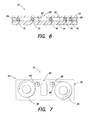
FIG. 3 is a cross-sectional schematic of the present invention, where the separators are flexible relative to the top and bottom planar members; -
FIG. 4 is a cross-sectional schematic of the present invention, where the top planar member is flexible in relation to all other elements; -
FIG. 5 is a cross-sectional schematic of the present invention, where the top planar member is flexible in relation to all other elements and where particulate debris has been trapped; -
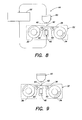
FIG. 6 is a schematic view of a first embodiment of the present invention; -
FIG. 6A is a schematic view of an instrument designed to utilize a second embodiment of the present invention; -
FIG. 7 is a schematic view of a cassette containing the first embodiment of the present invention; -
FIG. 8 is a schematic view of an instrument designed to utilize an embodiment of the present invention; -
FIG. 9 is a schematic view of the instrument ofFIG. 6 where the sample has been added to the planar member; -
FIG. 10 is a schematic view of the sample after spreading out between the planar members; and -
FIG. 11 is a schematic view of a typical field of view. - Referring to
FIGS. 3-11 , thepresent invention apparatus 10 for analyzing biologic fluid includes a firstplanar member 12, a secondplanar member 14, and at least threeseparators 16. At least one ofplanar members separators 16 are disposed between themembers planar members chamber 18 having aheight 20. At least one of themembers separators 16 is sufficiently flexible to permit thechamber height 20 between themembers separators 16. - The
separators 16 can be any structure that is disposable between theplanar members planar members separator 16 that extends between the planar members is referred to herein as theheight 22 of theseparator 16. Theheights 22 of theseparators 16 typically do not equal one another exactly, but are within commercially acceptable tolerance for spacing means used in similar analysis apparatus. Spherical beads are an example of anacceptable separator 16 and are commercially available from, for example, Bangs Laboratories of Fishers, Indiana, USA. - In some embodiments, the
separators 16 consist of a material that has greater flexibility than one or both of the firstplanar member 12 and the secondplanar member 14; i.e., relatively speaking, one or both of theplanar members separators 16 and theseparators 16 may be considered to be flexible relative to one or both of theplanar members - In other embodiments, the
separators 16 consist of a material that has less flexibility than one or both of the firstplanar member 12 and the secondplanar member 14; i.e., relatively speaking, one or both of theplanar members separators 16 and theseparators 16 may be considered to be rigid relative to one or both of theplanar members - Subject to the flexibility characteristics described above, the
planar members planar members planar members Planar members - Now referring to
FIG. 3 , in an embodiment of thepresent invention 10 the firstplanar member 12 and the secondplanar member 14 are separated by achamber 18 formed by plurality ofseparators 16 in the form of spherical beads. Thesebeads 16 are formed from a material that has greater flexibility than the firstplanar member 12 and the secondplanar member 14; i.e., theplanar members beads 16 and thebeads 16 may be considered to be flexible relative to theplanar members Plastic beads 16 formed from polystyrene, polycarbonate, silicone and the like can be used. In this example,larger beads 16A are compressed to the point where theplanar members most beads 16 are touching theinterior surfaces 24 of theplanar members chamber height 20 just slightly less than the mean bead diameter. - In
FIG. 4 , in another embodiment of thepresent invention 10 the firstplanar member 12 is formed from a material more flexible than thespherical beads 16 and the secondplanar member 14, and will overlay thebeads 16 in a tent-like fashion, where the areas between thebeads 16 are some arbitrary height determined by the bead diameters supporting that piece of theplanar member 12. Any transparent plastic film, such as acrylic, polystyrene, or the like will work provided it is thin enough to flex as shown. It should be apparent that in this circumstance, although small local areas will deviate from the desiredchamber height 20, the average height of all the tented areas will be very close to that of the mean bead diameter. Our testing indicates that that the mean chamber height can be controlled to 1% or better at chamber heights of less than four microns using the present invention. -
FIG. 5 shows thechamber 18 ofFIG. 4 wherein a piece ofparticulate debris 26 has lodged. The upperplanar member 12 over thedebris 26 has tented up, and the area under thedebris 26 is of unknown height, but this disturbance only affects a small area of thechamber 18, as opposed to what would occur if the whole system was rigid. -
FIG. 6 shows another embodiment of theinvention 10, where the secondplanar member 14 is formed from a one inch wide strip of transparent plastic film (e.g., polyethylene terphthalate (PET)) of approximately fifty (50) microns in thickness, the firstplanar member 12 is formed from the same material as the secondplanar member 14 but in twenty-three (23) micron thickness, and thechamber 18 therebetween is formed from a plurality ofplastic beads 16 with a mean diameter of four (4) microns. The firstplanar member 12 has an inner coating of a coloration agent, such as acridine orange, which will differentially color living white blood cells when examined with fluorescent illumination. Other reagents for fluorescence include astrozone orange, FITC, rhodamine and the like. Reagents which may be used with transmitted light to differentially color the white blood cells include astrozone orange, methylene blue, oxazine 170. The firstplanar member 12 includes a plurality of ports 28 (e.g., approximately three hundred (300) microns in diameter) punched at regular intervals, and theplanar members points 29 between theports 28 to form a series of separatedanalysis chambers 18. - This spacing between the two
planar members spherical beads 16 of known and precisely controlled diameter (e.g., about four (4) microns in diameter). Thesebeads 16 are randomly distributed on at least one of theplanar members beads 16 should be such that they remain affixed to theplanar member beads 16 is to suspend thebeads 16 in approximately a 0.5% solution ofphytagel and apply a thin coating of the suspension by either spraying or meniscus coating. The optimum concentration ofbeads 16 will depend upon the type of bead and their method of manufacture, as well as the relative rigidity of the top and bottomplanar members planar members bead 16 density to determine the point where additional bead concentration produces no useful change in liquid layer thickness; i.e., the point where thechamber height 20 is substantially uniform. An alternate means of providing the separators is to negatively emboss one of theplanar members planar member -
FIG. 7 shows acassette 30 having ashell 32 in which asource reel 34, a take-up reel 36, and atape 38 extending therebetween are disposed. The "tape 38" is the embodiment of the present invention shown inFIG. 6 and described above. Initially, thetape 38 is wound on thesource reel 34. Advancement of thetape 38 is controlled byrollers 40, which apply traction to thetape 38 at a point remote from theexamination area 42 and can act to draw thetape 38 from thesource reel 34 as required. Thecassette 30 has a through-hole that allows an optical system to provide illumination through thetape 38. -
FIG. 8 shows anoptical analysis system 44 containing thecassette 32. Theoptical analysis system 44, which consists of joined components including alens 46, a variable-wavelength light source 48 and aCCD camera 50 are movable in three dimensions so as to allow theoptical system 44 to focus upon thetape 38 in theexamination area 42 and provide X-Y movement so as to allow scanning of theentire examination area 42, all under control of asystem computer 52. Not shown is the sampling probe for extracting a biologic fluid (e.g., blood) from a sample tube and depositing a small drop on thetape 38. This sampling device can take the form of a tube-piercing or similar probe, which uses a stepping motor-driven syringe to extract and deposit biologic fluid samples. These devices are widely employed and well known to the art, and therefore will not be described further here. -
FIG. 9 shows the assembly ofFIG. 8 just after a drop of biologic fluid 54 (e.g., blood) has been deposited into the sample entry port 28 (seeFIG. 6 ) of achamber 18 formed between theplanar members -
FIG. 10 is a schematic view of the entire area of thesample film 64 ofbiologic fluid 34, which generally has an irregular border. In this example, the biologic fluid is blood. Because the white blood cells within thesample film 64 tend to become readily entrapped in thechamber 18, they are generally found in highest concentration within a few millimeters of theport 28. -
FIG. 11 is a schematic view of theanalysis field 66 inFIG. 10 , which, in the case of a whole blood sample, would showred blood cells 56,white blood cells 58,platelets 60, all surrounded by theblood plasma 62. Thebeads 16 are also seen but are readily distinguished from all other elements because of their size and refractive index. - The characterization of the white blood cells 58 (white blood cell differential count) is performed by the classification of each individual
white blood cell 58 as it is encountered using either traditional image-processing methods or by the technique described inU.S. Patent Nos. 5,321,975 and6,350,613 , both of which patents are hereby incorporated by reference. A number of supravital stains have been described which differentially color the different classes ofwhite blood cells 58 as has been described inU.S. Patent No. 6,235,536 , which is also hereby incorporated by reference. Because thewhite blood cells 58 are slightly compressed and readily imaged, stored images of cells are viewable by the technologist in the case of questionable cell classifications. - As an example of the utility of this invention, the
white blood cell 58 count of thesample film 64 may be performed by enumerating all of thewhite blood cells 58 found within thesample film 64 and dividing that number by the volume of thesample film 64. Although it is possible to deposit a specific amount of sample within thechamber 18, it is preferable to deposit an approximate amount and indirectly measure the volume. This can be done by mechanisms such as: 1) the volume of the drop of sample when first deposited can be calculated by interferometric imaging using optical techniques available from sources such as the Zygo Corporation of Middlefield, Connecticut USA; or 2) the volume of sample following film formation is calculated by measuring the area of thefilm 64 and multiplying this by the average height of the film. -
Figure 6A shows anoptical analysis system 44 containing another embodiment of thepresent invention 10 that includes acassette 30 in which a lowerplanar member reel 68, upperplanar member reel 70, and take-up reel 72. Advancement of theplanar members rollers 74, which apply traction to the combinedplanar members examination area 42 and can act to draw theplanar members reels optical analysis system 44, which consists of joined components including alens 46, a variable-wavelength light source 48 and aCCD camera 50 are movable in three dimensions so as to allow theoptical analysis system 44 to focus upon the joinedplanar members examination area 42 and provide X-Y movement so as to allow scanning of theentire examination area 42, all under control of asystem computer 52. A drop of biologic fluid 54 (e.g., blood) is shown deposited onto the secondplanar member 14. The nip-rollers 74 are operable to advance theplanar members rollers 74, where theseparators 16 disposed between theplanar members planar member interior surface 24 of eachplanar member thin sample film 64. Theplanar members optical analysis system 44. - Since the overall accuracy of the
system 44 when using a method of volume calculation depends upon the accuracy of thechamber height 20, it may be expedient to use an internal standard means to calculate theexact chamber height 20. An example of an internal standard includes a flexible or flowable material which is not miscible with the sample and which contains a known, stable and uniform concentration of a sensible optical dye. The material can be dyed flexible beads, dyed oil or the like, and may be present in one or more areas of thechamber 18. Since the optical density is in direct proportion to the thickness of the calibrator material, measurement of the optical density of the part of the calibrator material which completely fills thechamber height 20 will allow the calculation of theexact chamber height 20 to within the precision capabilities of the optical system. - Although the most frequent use for such a
chamber 18 will be for enumerating blood cells in whole blood, it is equally useful for examination of any undiluted fluid having sufficient particles to count. Thechamber height 20 is not limited to the disclosed four microns but can be larger or smaller to accommodate different separator sizes and/or concentrations. - Although this invention has been shown and described with respect to the detailed embodiments thereof, it will be understood by those skilled in the art that various changes in form and detail thereof may be made without departing from the scope of the invention, which is defined by the following claims.
Claims (15)
- An apparatus for analyzing biologic fluid, comprising:a tape including a first planar member and a second planar member spaced apart from one another and bonded together at discrete points, wherein at least one of the first planar member and second planar member is transparent, and at least one chamber having a height is formed between the planar members, and at least three separators are disposed in each of the at least one chamber, and wherein at least one of the first planar member, second planar member, or separators is flexible to permit the chamber height to be substantially uniform;a source reel on which the tape may be wound; anda take-up reel on which the tape may be wound.
- The apparatus of claim 1, wherein the at least one chamber includes a port.
- The apparatus of any preceding claim, wherein one of the separators, first planar member, and second planar member, has a greater flexibility relative to at least one of the others of the separators, first planar member, and second planar member.
- The apparatus of claim 3, wherein the first planar member has a greater flexibility than the second planar member and the separators.
- The apparatus of any preceding claim, wherein at least one of the first planar member and the second planar member comprise flexible plastic.
- The apparatus of claim 5, wherein both of the first planar member and the second planar member comprise flexible plastic.
- The apparatus of any preceding claim, wherein the separators are attached to at least one of the first planar member or the second planar member.
- The apparatus of any of claims 1-5, wherein one of the first planar member or the second planar member comprises linked rigid elements and the other of the first planar member or second planar member comprises flexible plastic.
- The apparatus of any preceding claim, wherein the separators include uniformly dyed, slightly compressible plastic beads.
- An apparatus for analyzing biologic fluid, comprising:a first planar member;a first source reel;a second planar member, wherein at least one of the first planar member and second planar member is transparent,a second source reel;a plurality of separators attached to one of the first planar member or second planar;a pair of nip-rollers, spaced apart from one another an amount that causes the first planar member and second planar member to be in contact with substantially all of the separators when the planar members are drawn between the nip-rollers;at least one chamber having a height, which chamber is formed between the planar members downstream of the nip-rollers, and wherein at least one of the first planar member, second planar member, or separators is flexible to permit the chamber height to be substantially uniform; andat least one take-up reel for receiving one or both of the planar members.
- The apparatus of claim 10, wherein one of the separators, first planar member, and second planar member, has a greater flexibility relative to at least one of the others of the separators, first planar member, and second planar member.
- The apparatus of claim 11, wherein the first planar member has a greater flexibility than the second planar member and the separators.
- The apparatus of claim 10 wherein one of the first planar member or the second planar member comprises linked rigid elements and the other of the first planar member or second planar member comprises flexible plastic.
- A method of enumerating the cellular or particulate constituents of a sample of whole, anticoagulated blood, comprising the steps of:providing a tape including a first planar member and a second planar member spaced apart from one another and bonded together at discrete points, wherein at least one of the first planar member and second planar member is transparent, and at least one chamber having a height is formed between the planar members, and at least three separators are disposed in each of the at least one chamber, and wherein at least one of the first planar member, second planar member, or separators is flexible to permit the chamber height to be substantially uniform, a source reel on which the tape may be wound, and a take-up reel on which the tape may be wound;depositing a quantity of biologic fluid into the at least one chamber;determining the volume of biologic fluid contained within at least a portion of the at least one chamber;directly or indirectly enumerating all constituents of interest within substantially the volume of biologic fluid; andexpressing the enumerated constituents as a count per unit volume.
- An apparatus for analyzing biologic fluid, comprising:a first planar member;a second planar member, wherein at least one of the first planar member and second planar member is transparent; andat least three separators disposed between the planar members, separating the planar members to form a chamber having a height extending between the planar members;wherein at least one of the first planar member, second planar member, or separators is flexible to permit the chamber height to be substantially uniform.
Priority Applications (1)
| Application Number | Priority Date | Filing Date | Title |
|---|---|---|---|
| EP17189563.4A EP3270156A1 (en) | 2004-04-07 | 2005-04-07 | Disposable chamber for analyzing biologic fluids |
Applications Claiming Priority (2)
| Application Number | Priority Date | Filing Date | Title |
|---|---|---|---|
| US56030704P | 2004-04-07 | 2004-04-07 | |
| EP05732677.9A EP1733226B1 (en) | 2004-04-07 | 2005-04-07 | Disposable chamber for analyzing biologic fluids |
Related Parent Applications (1)
| Application Number | Title | Priority Date | Filing Date |
|---|---|---|---|
| EP05732677.9A Division EP1733226B1 (en) | 2004-04-07 | 2005-04-07 | Disposable chamber for analyzing biologic fluids |
Related Child Applications (1)
| Application Number | Title | Priority Date | Filing Date |
|---|---|---|---|
| EP17189563.4A Division EP3270156A1 (en) | 2004-04-07 | 2005-04-07 | Disposable chamber for analyzing biologic fluids |
Publications (2)
| Publication Number | Publication Date |
|---|---|
| EP2977757A1 true EP2977757A1 (en) | 2016-01-27 |
| EP2977757B1 EP2977757B1 (en) | 2017-09-13 |
Family
ID=35150548
Family Applications (3)
| Application Number | Title | Priority Date | Filing Date |
|---|---|---|---|
| EP05732677.9A Expired - Lifetime EP1733226B1 (en) | 2004-04-07 | 2005-04-07 | Disposable chamber for analyzing biologic fluids |
| EP17189563.4A Withdrawn EP3270156A1 (en) | 2004-04-07 | 2005-04-07 | Disposable chamber for analyzing biologic fluids |
| EP15178645.6A Expired - Lifetime EP2977757B1 (en) | 2004-04-07 | 2005-04-07 | Disposable chamber for analyzing biologic fluids |
Family Applications Before (2)
| Application Number | Title | Priority Date | Filing Date |
|---|---|---|---|
| EP05732677.9A Expired - Lifetime EP1733226B1 (en) | 2004-04-07 | 2005-04-07 | Disposable chamber for analyzing biologic fluids |
| EP17189563.4A Withdrawn EP3270156A1 (en) | 2004-04-07 | 2005-04-07 | Disposable chamber for analyzing biologic fluids |
Country Status (8)
| Country | Link |
|---|---|
| US (4) | US7850916B2 (en) |
| EP (3) | EP1733226B1 (en) |
| JP (1) | JP4362532B2 (en) |
| CN (1) | CN1957254B (en) |
| AU (1) | AU2005233571B2 (en) |
| CA (1) | CA2563002C (en) |
| ES (2) | ES2548567T3 (en) |
| WO (1) | WO2005100539A2 (en) |
Families Citing this family (149)
| Publication number | Priority date | Publication date | Assignee | Title |
|---|---|---|---|---|
| WO2005100539A2 (en) | 2004-04-07 | 2005-10-27 | Levine, Robert, A. | Disposable chamber for analyzing biologic fluids |
| US7731901B2 (en) | 2005-10-19 | 2010-06-08 | Abbott Laboratories | Apparatus and method for performing counts within a biologic fluid sample |
| HU227018B1 (en) | 2006-10-26 | 2010-04-28 | 77 Elektronika Mueszeripari Kf | Container to examine urine |
| CN102016686B (en) * | 2008-03-21 | 2015-03-25 | 艾博特健康公司 | Method and apparatus for determining focus position of an imaging device imaging a biological sample |
| ES2588223T3 (en) | 2008-03-21 | 2016-10-31 | Abbott Point Of Care, Inc. | Procedure for the analysis of individual cells or particles in the blood using fluorescence and absorption of a dye |
| EP2265945B1 (en) * | 2008-03-21 | 2012-11-07 | Abbott Point Of Care, Inc. | Method and apparatus for determining red blood cell indices of a blood sample utilizing the intrinsic pigmentation of hemoglobin contained within the red blood cells |
| CN102016578B (en) | 2008-03-21 | 2014-10-01 | 艾博特健康公司 | Method and apparatus for determining the hematocrit of a blood sample using the intrinsic pigmentation of hemoglobin contained in red blood cells |
| ES2560098T3 (en) | 2008-03-21 | 2016-02-17 | Abbott Point Of Care, Inc. | Method and apparatus for detecting and counting platelets individually and in aggregates |
| WO2009124179A1 (en) | 2008-04-02 | 2009-10-08 | Abbott Point Of Care, Inc. | Virtual separation of bound and free label in a ligand assay for performing immunoassays of biological fluids, including whole blood |
| WO2009126800A1 (en) | 2008-04-09 | 2009-10-15 | Abbott Point Of Care, Inc. | Method for measuring the area of a sample disposed within an analysis chamber |
| WO2009126505A1 (en) * | 2008-04-09 | 2009-10-15 | Abbott Point Of Care, Inc. | Method of detecting very low levels of analyte within a thin film fluid sample contained in a thin thickness chamber |
| CN102131737B (en) | 2008-08-21 | 2014-03-19 | 西门子医疗保健诊断公司 | Multilayer Slides for Urine Sediment Analysis |
| US20100255605A1 (en) * | 2009-04-02 | 2010-10-07 | Abbott Point Of Care, Inc. | Method and device for transferring biologic fluid samples |
| US9395365B2 (en) * | 2009-04-02 | 2016-07-19 | Abbott Point Of Care, Inc. | Detection of infectious disease in a human or animal by measuring specific phagocytosis in a thin film sample of their anticoagulated blood |
| US9075225B2 (en) | 2009-10-28 | 2015-07-07 | Alentic Microscience Inc. | Microscopy imaging |
| US20140152801A1 (en) | 2009-10-28 | 2014-06-05 | Alentic Microscience Inc. | Detecting and Using Light Representative of a Sample |
| WO2011053631A1 (en) | 2009-10-28 | 2011-05-05 | Alentic Microscience Inc. | Microscopy imaging |
| US10746752B2 (en) * | 2009-11-13 | 2020-08-18 | Ventana Medical Systems, Inc. | Opposables and automated specimen processing systems with opposables |
| US9500645B2 (en) | 2009-11-23 | 2016-11-22 | Cyvek, Inc. | Micro-tube particles for microfluidic assays and methods of manufacture |
| US10065403B2 (en) | 2009-11-23 | 2018-09-04 | Cyvek, Inc. | Microfluidic assay assemblies and methods of manufacture |
| US9700889B2 (en) | 2009-11-23 | 2017-07-11 | Cyvek, Inc. | Methods and systems for manufacture of microarray assay systems, conducting microfluidic assays, and monitoring and scanning to obtain microfluidic assay results |
| US9651568B2 (en) | 2009-11-23 | 2017-05-16 | Cyvek, Inc. | Methods and systems for epi-fluorescent monitoring and scanning for microfluidic assays |
| WO2011063408A1 (en) | 2009-11-23 | 2011-05-26 | Cyvek, Inc. | Method and apparatus for performing assays |
| US9855735B2 (en) | 2009-11-23 | 2018-01-02 | Cyvek, Inc. | Portable microfluidic assay devices and methods of manufacture and use |
| US9759718B2 (en) | 2009-11-23 | 2017-09-12 | Cyvek, Inc. | PDMS membrane-confined nucleic acid and antibody/antigen-functionalized microlength tube capture elements, and systems employing them, and methods of their use |
| US9579651B2 (en) | 2009-12-18 | 2017-02-28 | Abbott Point Of Care, Inc. | Biologic fluid analysis cartridge |
| ES2438841T3 (en) | 2009-12-31 | 2014-01-20 | Abbott Point Of Care, Inc. | Method and apparatus for determining the average cell volume of red blood cells in the blood |
| CN102782559B (en) | 2009-12-31 | 2015-11-25 | 雅培照护点公司 | For focusing on method and the device of the image forming biological specimen fast |
| JP5723890B2 (en) * | 2009-12-31 | 2015-05-27 | アボット ポイント オブ ケア インコーポレイテッド | Method and apparatus for ensuring planar motion of analysis chamber |
| CN102762713B (en) * | 2010-01-20 | 2016-04-27 | Emd密理博公司 | Cell Image Capture and Remote Monitoring System |
| US8472693B2 (en) | 2010-03-18 | 2013-06-25 | Abbott Point Of Care, Inc. | Method for determining at least one hemoglobin related parameter of a whole blood sample |
| WO2011123649A1 (en) | 2010-03-31 | 2011-10-06 | Abbott Point Of Care, Inc. | Method and apparatus for selectively admixing reagents in a substantially undiluted biologic fluid sample analysis |
| US9199233B2 (en) | 2010-03-31 | 2015-12-01 | Abbott Point Of Care, Inc. | Biologic fluid analysis cartridge with deflecting top panel |
| US8481282B2 (en) | 2010-07-23 | 2013-07-09 | Abbott Point Of Care, Inc. | Method for detecting the presence of anisotropic crystals in undiluted whole blood |
| WO2012019118A1 (en) | 2010-08-05 | 2012-02-09 | Abbott Point Of Care, Inc. | Method and apparatus for automated whole blood sample analyses from microscopy images |
| US9522396B2 (en) | 2010-12-29 | 2016-12-20 | S.D. Sight Diagnostics Ltd. | Apparatus and method for automatic detection of pathogens |
| ES2533839T3 (en) | 2010-12-30 | 2015-04-15 | Abbott Point Of Care, Inc. | Biological fluid analysis cartridge with sample manipulation portion and analysis chamber portion |
| JP5978287B2 (en) * | 2011-03-22 | 2016-08-24 | サイヴェク・インコーポレイテッド | Microfluidic device and method of manufacture and use |
| US9064301B2 (en) | 2011-04-14 | 2015-06-23 | Abbott Point Of Care, Inc. | Method and apparatus for compressing imaging data of whole blood sample analyses |
| CN105817276B (en) | 2011-08-24 | 2018-02-06 | 艾博特健康公司 | Biologicfluid sample analyzes box |
| US9523682B2 (en) | 2011-11-16 | 2016-12-20 | Becton, Dickinson And Company | Methods and systems for detecting an analyte in a sample |
| CN104169719B (en) | 2011-12-29 | 2017-03-08 | 思迪赛特诊断有限公司 | Methods and systems for detecting pathogens in biological samples |
| CN104080534B (en) | 2011-12-30 | 2017-05-24 | 艾博特健康公司 | Method for rapid imaging of biologic fluid samples |
| EP2798352B1 (en) | 2011-12-30 | 2015-11-25 | Abbott Point Of Care, Inc. | Method and apparatus for automated platelet identification within a whole blood sample from microscopy images |
| WO2013102201A1 (en) | 2011-12-31 | 2013-07-04 | Abbott Point Of Care, Inc. | Biologic fluid sample analysis cartridge with sample collection port |
| EP2822688B1 (en) | 2012-03-08 | 2019-09-25 | Cyvek, Inc. | Microfluidic assay assemblies and methods of manufacture |
| EP2929345A4 (en) | 2012-12-06 | 2015-11-18 | Abbott Point Of Care Inc | IMAGING BIOLOGICAL LIQUIDS USING A PREDETERMINED DISTRIBUTION |
| AU2014205215B2 (en) | 2013-01-11 | 2019-02-14 | Becton, Dickinson And Company | Low-cost point-of-care assay device |
| US10502666B2 (en) | 2013-02-06 | 2019-12-10 | Alentic Microscience Inc. | Sample processing improvements for quantitative microscopy |
| US9518920B2 (en) | 2013-06-26 | 2016-12-13 | Alentic Microscience Inc. | Sample processing improvements for microscopy |
| EP3489644A1 (en) * | 2013-02-19 | 2019-05-29 | Abbott Point Of Care, Inc. | Biologic fluid sample analysis cartridge with non-reflective beads |
| EP3869257B1 (en) | 2013-05-23 | 2024-05-08 | S.D. Sight Diagnostics Ltd. | Method and system for imaging a cell sample |
| IL227276A0 (en) | 2013-07-01 | 2014-03-06 | Parasight Ltd | A method and system for obtaining a monolayer of cells, for use specifically for diagnosis |
| US20150030215A1 (en) * | 2013-07-26 | 2015-01-29 | Abbott Point Of Care, Inc. | Method and apparatus for producing an image of undiluted whole blood sample having wright stain coloration |
| US10831013B2 (en) | 2013-08-26 | 2020-11-10 | S.D. Sight Diagnostics Ltd. | Digital microscopy systems, methods and computer program products |
| CN113477149B (en) | 2013-11-06 | 2023-09-12 | 贝克顿·迪金森公司 | Microfluidic devices and methods of making and using the same |
| JP6518245B2 (en) | 2013-11-13 | 2019-05-22 | ベクトン・ディキンソン・アンド・カンパニーBecton, Dickinson And Company | Optical imaging system and method using the same |
| CN107077732B (en) | 2014-08-27 | 2020-11-24 | 思迪赛特诊断有限公司 | System and method for calculating focus changes for digital microscopes |
| JP6417038B2 (en) | 2014-10-14 | 2018-10-31 | ベクトン・ディキンソン・アンド・カンパニーBecton, Dickinson And Company | Blood sample management using open cell foam |
| AU2015334046B2 (en) | 2014-10-14 | 2017-04-13 | Becton, Dickinson And Company | Blood sample management using open cell foam |
| US20170328924A1 (en) | 2014-11-26 | 2017-11-16 | Ronald Jones | Automated microscopic cell analysis |
| US11478789B2 (en) | 2014-11-26 | 2022-10-25 | Medica Corporation | Automated microscopic cell analysis |
| US10625259B1 (en) | 2014-11-26 | 2020-04-21 | Medica Corporation | Automated microscopic cell analysis |
| US12005441B1 (en) | 2014-11-26 | 2024-06-11 | Medica Corporation | Automated microscopic cell analysis |
| EP3154697B1 (en) | 2015-03-10 | 2018-06-20 | Becton, Dickinson and Company | Biological fluid micro-sample management device |
| CA2995204A1 (en) * | 2015-08-10 | 2017-02-16 | Essenlix Corp. | Bio/chemical assay devices and methods for simplified steps, small samples, accelerated speed, and ease-of-use |
| JP2018536142A (en) | 2015-09-01 | 2018-12-06 | ベクトン・ディキンソン・アンド・カンパニーBecton, Dickinson And Company | Depth filtration device for separating sample phases |
| KR20190057445A (en) * | 2015-09-14 | 2019-05-28 | 에센릭스 코프. | Device and system for analyzing a sample, particularly blood, as well as methods of using the same |
| US10132794B2 (en) | 2015-09-14 | 2018-11-20 | Essenlix Corporation | Device and system for collecting and analyzing vapor condensate, particularly exhaled breath condensate, as well as method of using the same |
| WO2017045712A1 (en) * | 2015-09-16 | 2017-03-23 | Siemens Healthcare Gmbh | Arrangement and method for providing a sample for inspection by an imaging device |
| EP3859425B1 (en) | 2015-09-17 | 2024-04-17 | S.D. Sight Diagnostics Ltd. | Methods and apparatus for detecting an entity in a bodily sample |
| EP3368220B1 (en) | 2015-10-26 | 2020-07-22 | IDEXX Laboratories, Inc. | Hematology test slide |
| US10228367B2 (en) | 2015-12-01 | 2019-03-12 | ProteinSimple | Segmented multi-use automated assay cartridge |
| US10782306B2 (en) | 2015-12-24 | 2020-09-22 | Koninklijke Philips N.V. | Method and a system for determinations of cell suspensions |
| US11733150B2 (en) | 2016-03-30 | 2023-08-22 | S.D. Sight Diagnostics Ltd. | Distinguishing between blood sample components |
| US10317662B2 (en) | 2016-04-08 | 2019-06-11 | Alentic Microscience Inc. | Sample processing for microscopy |
| AU2017263807B2 (en) | 2016-05-11 | 2023-02-02 | S.D. Sight Diagnostics Ltd | Performing optical measurements on a sample |
| US11307196B2 (en) | 2016-05-11 | 2022-04-19 | S.D. Sight Diagnostics Ltd. | Sample carrier for optical measurements |
| CN107525805A (en) * | 2016-06-20 | 2017-12-29 | 亿观生物科技股份有限公司 | Sample detection device and sample detection system |
| EP3282262A1 (en) * | 2016-08-10 | 2018-02-14 | CytoScience SA | Cassette for a microscope, microscope with such a cassette and method of microscoping with such a microscope |
| US10628693B2 (en) | 2016-12-21 | 2020-04-21 | Essenlix Corporation | Devices and methods for authenticating a sample and use of the same |
| JP7003158B2 (en) * | 2017-02-07 | 2022-01-20 | エッセンリックス コーポレーション | Compressed open flow assay and use |
| CN122234927A (en) | 2017-02-08 | 2026-06-19 | 上海宜晟生物科技有限公司 | Molecular manipulation and detection by controlling temperature |
| CA3052809A1 (en) | 2017-02-08 | 2018-08-23 | Essenlix Corporation | Qmax assays and applications |
| WO2018148729A1 (en) * | 2017-02-08 | 2018-08-16 | Essenlix Corporation | Qmax card-based assay devices and methods |
| WO2018148470A1 (en) * | 2017-02-08 | 2018-08-16 | Essenlix Corporation | Sample collection and handling for delayed analysis |
| US12569851B2 (en) | 2017-02-08 | 2026-03-10 | Essenlix Corporation | Digital assay |
| CA3053002A1 (en) | 2017-02-08 | 2018-08-16 | Essenlix Corp. | Bio/chemical material extraction and assay |
| CA3053132A1 (en) | 2017-02-09 | 2018-08-16 | Essenlix Corp. | Assay with amplification |
| WO2018148606A1 (en) * | 2017-02-09 | 2018-08-16 | Essenlix Corporation | Qmax assay and applications (ii) |
| CA3053114A1 (en) * | 2017-02-09 | 2018-08-16 | Essenlix Corporation | Assay using different spacing heights |
| JP2020507770A (en) * | 2017-02-09 | 2020-03-12 | エッセンリックス コーポレーション | Colorimetric assay |
| CA3053295A1 (en) * | 2017-02-15 | 2018-08-23 | Essenlix Corporation | Assay with rapid temperature change |
| WO2018152351A1 (en) * | 2017-02-15 | 2018-08-23 | Essenlix Corporation | Assay with rapid temperature change |
| WO2018152422A1 (en) * | 2017-02-16 | 2018-08-23 | Essenlix Corporation | Assay with textured surface |
| CN110891684B (en) * | 2017-02-16 | 2022-08-30 | Essenlix公司 | QMAX card-based measurement device and method |
| CN111448449B (en) | 2017-02-16 | 2024-08-27 | 上海宜晟生物科技有限公司 | Measurement method and device using textured surface |
| JP7335816B2 (en) | 2017-05-23 | 2023-08-30 | エッセンリックス コーポレーション | Rapid sample temperature change for assays |
| US12181472B2 (en) | 2017-06-12 | 2024-12-31 | Essenlix Corporation | Homogeneous assay |
| EP3642615B1 (en) | 2017-06-20 | 2022-04-06 | DeLaval Holding AB | Arrangement, cassette and service module for biomarker analysis of a milk sample |
| WO2019027963A1 (en) * | 2017-07-31 | 2019-02-07 | Essenlix Corporation | Assays with reduced interference |
| US11280706B2 (en) | 2017-08-01 | 2022-03-22 | Essenlix Corporation | Dilution calibration |
| CN111492222A (en) * | 2017-08-01 | 2020-08-04 | Essenlix公司 | Sample collection, retention and assay |
| US11725227B2 (en) | 2017-08-01 | 2023-08-15 | Essenlix Corporation | Devices and methods for examining drug effects on microorganisms |
| US20190056384A1 (en) | 2017-08-17 | 2019-02-21 | Abbott Point Of Care Inc. | Single-use test device for imaging assay beads |
| US20190056385A1 (en) | 2017-08-17 | 2019-02-21 | Abbott Point Of Care Inc. | Method of imaging assay beads in a biological sample |
| WO2019035082A1 (en) | 2017-08-17 | 2019-02-21 | Abbott Point Of Care Inc. | Techniques for performing optical and electrochemical assays with universal circuitry |
| WO2019035085A1 (en) | 2017-08-17 | 2019-02-21 | Abbott Point Of Care Inc. | A method of imaging blood cells |
| CN110892247B (en) | 2017-08-17 | 2023-08-25 | 雅培医护站股份有限公司 | Apparatus, systems, and methods for performing optical and electrochemical assays |
| CN110869745B (en) | 2017-08-17 | 2023-08-11 | 雅培医护站股份有限公司 | Devices, systems and methods for performing optical assays |
| CN111183350A (en) | 2017-08-17 | 2020-05-19 | 雅培医护站股份有限公司 | Single-use test device for imaging blood cells |
| WO2019075244A1 (en) | 2017-10-11 | 2019-04-18 | Essenlix Corporation | Containing a liquid sample |
| WO2019075415A1 (en) | 2017-10-13 | 2019-04-18 | Essenlix Corporation | Devices and methods for authenticating a medical test and use of the same |
| US11237113B2 (en) | 2017-10-26 | 2022-02-01 | Essenlix Corporation | Rapid pH measurement |
| US11609224B2 (en) | 2017-10-26 | 2023-03-21 | Essenlix Corporation | Devices and methods for white blood cell analyses |
| US10807095B2 (en) | 2017-10-26 | 2020-10-20 | Essenlix Corporation | Making and tracking assay card |
| US20190170734A1 (en) * | 2017-10-26 | 2019-06-06 | Essenlix Corporation | Compact Illuminator, Imaging and Systems and the Use of the Same |
| EP3710810B1 (en) | 2017-11-14 | 2023-09-06 | S.D. Sight Diagnostics Ltd. | Sample carrier for optical measurements |
| US11047845B1 (en) | 2017-11-15 | 2021-06-29 | Medica Corporation | Control material and methods for cell analyzers |
| WO2019118652A1 (en) | 2017-12-12 | 2019-06-20 | Essenlix Corporation | Sample manipulation and assay with rapid temperature change |
| CN112534259A (en) | 2017-12-14 | 2021-03-19 | Essenlix公司 | Device, system and method for monitoring hair |
| WO2019140334A1 (en) | 2018-01-11 | 2019-07-18 | Essenlix Corporation | Homogeneous assay (ii) |
| JP2021512299A (en) * | 2018-01-25 | 2021-05-13 | エッセンリックス コーポレーション | Parallel assay of cells and non-cell analysts in a sample |
| US11885952B2 (en) | 2018-07-30 | 2024-01-30 | Essenlix Corporation | Optics, device, and system for assaying and imaging |
| WO2020037304A1 (en) * | 2018-08-16 | 2020-02-20 | Essenlix Corporation | Assay using sample thickness multiplexing |
| CN113227755B (en) * | 2018-08-28 | 2025-06-27 | 上海宜晟生物科技有限公司 | Improved measurement accuracy |
| USD897555S1 (en) | 2018-11-15 | 2020-09-29 | Essenlix Corporation | Assay card |
| USD898224S1 (en) | 2018-11-15 | 2020-10-06 | Essenlix Corporation | Assay plate with sample landing mark |
| USD898221S1 (en) | 2018-11-15 | 2020-10-06 | Essenlix Corporation | Assay plate |
| WO2020106909A1 (en) * | 2018-11-20 | 2020-05-28 | Essenlix Corporation | Apparatus and methods for rapid detection of acute phase reactants and white blood cells |
| USD898939S1 (en) | 2018-11-20 | 2020-10-13 | Essenlix Corporation | Assay plate with sample landing mark |
| USD910202S1 (en) | 2018-11-21 | 2021-02-09 | Essenlix Corporation | Assay plate with sample landing mark |
| USD893469S1 (en) | 2018-11-21 | 2020-08-18 | Essenlix Corporation | Phone holder |
| USD910203S1 (en) | 2018-11-27 | 2021-02-09 | Essenlix Corporation | Assay plate with sample landing mark |
| USD893470S1 (en) | 2018-11-28 | 2020-08-18 | Essenlix Corporation | Phone holder |
| USD912842S1 (en) | 2018-11-29 | 2021-03-09 | Essenlix Corporation | Assay plate |
| USD898222S1 (en) | 2019-01-18 | 2020-10-06 | Essenlix Corporation | Assay card |
| USD1003453S1 (en) | 2019-05-14 | 2023-10-31 | Essenlix Corporation | Assay card hinge |
| WO2020243741A1 (en) | 2019-05-28 | 2020-12-03 | Levine Robert A | Apparatus and method for transferring and analyzing suspended particles in a liquid sample |
| USD907244S1 (en) | 2019-06-14 | 2021-01-05 | Emd Millipore Corporation | Cell imager |
| US11712177B2 (en) | 2019-08-12 | 2023-08-01 | Essenlix Corporation | Assay with textured surface |
| CN114514419A (en) * | 2019-10-01 | 2022-05-17 | 诺尔有限公司 | Body fluid analyzer and body fluid analyzing method using the same |
| KR102931515B1 (en) | 2019-10-22 | 2026-02-27 | 에스.디. 사이트 다이그노틱스 엘티디 | Consideration of errors in optical measurements |
| BR112022011233A2 (en) | 2019-12-12 | 2022-08-30 | S D Sight Diagnostics Ltd | DETECTION OF PLATELETS IN A BLOOD SAMPLE |
| BR112022011354A2 (en) | 2019-12-12 | 2022-08-23 | S D Sight Diagnostics Ltd | ARTIFICIAL GENERATION OF A COLOR BLOOD SCRAPT IMAGE |
| BR112022011312A2 (en) | 2019-12-12 | 2022-08-23 | S D Sight Diagnostics Ltd | ANALYSIS OF AN ANALYTE DISPOSED IN A MEDIUM |
| CN112557686A (en) * | 2020-12-28 | 2021-03-26 | 广州禾信仪器股份有限公司 | Sample introduction card, sample introduction device and detection equipment |
| NL2028670B1 (en) * | 2021-07-08 | 2023-01-16 | Vitrotem B V | Thin-film-based assembly. |
| WO2024220478A1 (en) * | 2023-04-21 | 2024-10-24 | Twist Bioscience Corporation | Parallel substrates for multiplexing biomolecule processing |
Citations (11)
| Publication number | Priority date | Publication date | Assignee | Title |
|---|---|---|---|---|
| GB1049364A (en) * | 1962-07-20 | 1966-11-23 | Warner Lambert Pharmaceutical | An apparatus for and a method of automatically analyzing a plurality of samples |
| US3447863A (en) * | 1966-07-11 | 1969-06-03 | Sodell Research & Dev Co | Method for preparing a slide for viewing |
| US3607090A (en) * | 1969-10-06 | 1971-09-21 | Scientific Industries | Analysis arrangment for multiple analyses of a single sample |
| US4264560A (en) * | 1979-12-26 | 1981-04-28 | Samuel Natelson | Clinical analytical system |
| US4950455A (en) | 1987-12-22 | 1990-08-21 | Board Of Regents, University Of Texas System | Apparatus for quantifying components in liquid samples |
| US5321975A (en) | 1991-10-04 | 1994-06-21 | Levine Robert A | Differential erythrocyte counts |
| US5448874A (en) * | 1992-08-21 | 1995-09-12 | Millipore S.A. | Method and apparatus for removing objects from sterile packaging |
| US6235536B1 (en) | 1998-03-07 | 2001-05-22 | Robert A. Levine | Analysis of quiescent anticoagulated whole blood samples |
| US6350613B1 (en) | 1998-03-07 | 2002-02-26 | Belton Dickinson & Co. | Determination of white blood cell differential and reticulocyte counts |
| US6551554B1 (en) * | 1995-02-15 | 2003-04-22 | Leja Products B.V. | Counting compartment for biological investigations and a method for manufacturing such a counting compartment |
| US20040048330A1 (en) * | 2000-07-10 | 2004-03-11 | Christoph Bittner | Method for the examination of cells in a culture medium |
Family Cites Families (128)
| Publication number | Priority date | Publication date | Assignee | Title |
|---|---|---|---|---|
| US3879106A (en) | 1973-04-11 | 1975-04-22 | Pelam Inc | Microscope slide cover slip |
| US4022521A (en) | 1974-02-19 | 1977-05-10 | Honeywell Inc. | Microscope slide |
| US4171866A (en) | 1978-04-20 | 1979-10-23 | Tolles Walter E | Disposable volumetric slide |
| US4218421A (en) * | 1978-08-18 | 1980-08-19 | Honeywell Inc. | Disposable container for a continuous band of test strips |
| US4329054A (en) * | 1979-08-16 | 1982-05-11 | Spectron Development Laboratories, Inc. | Apparatus for sizing particles, droplets or the like with laser scattering |
| US4338024A (en) | 1980-05-02 | 1982-07-06 | International Remote Imaging Systems, Inc. | Flow analyzer and system for analysis of fluids with particles |
| US4447140A (en) | 1982-09-29 | 1984-05-08 | Campbell Jeptha E | Microscope slides |
| FR2565350B1 (en) * | 1984-06-05 | 1986-10-10 | Paris Nord Universite | PROPER MEANS FOR ALLOWING AUTOMATIC CONTINUOUS SUPPORT, PROCESSING, STORAGE AND ANALYSIS OF BIOLOGICAL SAMPLES |
| US4689307A (en) | 1986-09-02 | 1987-08-25 | Caribbean Microparticles Corporation | Fluorescence microscopy sample mounting method and structure |
| DE3721237A1 (en) | 1987-06-27 | 1989-01-05 | Boehringer Mannheim Gmbh | DIAGNOSTIC TEST CARRIER AND METHOD FOR THE PRODUCTION THEREOF |
| US5039487A (en) | 1987-12-22 | 1991-08-13 | Board Of Regents, The University Of Texas System | Methods for quantifying components in liquid samples |
| US5503803A (en) | 1988-03-28 | 1996-04-02 | Conception Technologies, Inc. | Miniaturized biological assembly |
| US5472671A (en) | 1989-04-26 | 1995-12-05 | Nilsson; Sven-Erik | Cuvette |
| US5184188A (en) | 1990-01-23 | 1993-02-02 | Medical Devices Corporation | Optical blood hemostatic analysis apparatus and method |
| US6176962B1 (en) | 1990-02-28 | 2001-01-23 | Aclara Biosciences, Inc. | Methods for fabricating enclosed microchannel structures |
| SE470347B (en) | 1990-05-10 | 1994-01-31 | Pharmacia Lkb Biotech | Microstructure for fluid flow systems and process for manufacturing such a system |
| JP3368477B2 (en) | 1992-06-26 | 2003-01-20 | 日水製薬株式会社 | Optical measuring device |
| US5585246A (en) | 1993-02-17 | 1996-12-17 | Biometric Imaging, Inc. | Method for preparing a sample in a scan capillary for immunofluorescent interrogation |
| US5547849A (en) | 1993-02-17 | 1996-08-20 | Biometric Imaging, Inc. | Apparatus and method for volumetric capillary cytometry |
| CA2175056A1 (en) | 1993-10-28 | 1995-05-04 | Imants R. Lauks | Fluid sample collection and introduction device |
| CA2156226C (en) | 1994-08-25 | 1999-02-23 | Takayuki Taguchi | Biological fluid analyzing device and method |
| US5627041A (en) | 1994-09-02 | 1997-05-06 | Biometric Imaging, Inc. | Disposable cartridge for an assay of a biological sample |
| US5504011A (en) | 1994-10-21 | 1996-04-02 | International Technidyne Corporation | Portable test apparatus and associated method of performing a blood coagulation test |
| NL1000607C1 (en) | 1995-02-07 | 1996-08-07 | Hendrik Jan Westendorp | Counting chamber and method for manufacturing a counting chamber |
| SE504193C2 (en) | 1995-04-21 | 1996-12-02 | Hemocue Ab | Capillary microcuvette |
| US5641458A (en) | 1995-06-15 | 1997-06-24 | Shockley, Jr.; H. David | Flow through cell assembly |
| US6130098A (en) | 1995-09-15 | 2000-10-10 | The Regents Of The University Of Michigan | Moving microdroplets |
| US5726751A (en) * | 1995-09-27 | 1998-03-10 | University Of Washington | Silicon microchannel optical flow cytometer |
| US5837547A (en) | 1995-12-27 | 1998-11-17 | Caribbean Microparticles Corporation | Flow cytometer calibration method |
| US5985218A (en) | 1996-07-03 | 1999-11-16 | Beckman Coulter, Inc. | Reagent cartridge |
| EP0929658A4 (en) * | 1996-08-26 | 2005-11-02 | Univ Princeton | DEVICES FOR SORTING MICROSTRUCTURES THAT CAN BE REVERSIBLELY SEALED |
| US5968453A (en) | 1997-07-17 | 1999-10-19 | Carolina Liquid Chemistries Corporation | Reagent cartridge |
| US5812312A (en) * | 1997-09-04 | 1998-09-22 | Lorincz; Andrew Endre | Microscope slide |
| US6016712A (en) | 1997-09-18 | 2000-01-25 | Accumetrics | Device for receiving and processing a sample |
| AU737907B2 (en) | 1997-10-31 | 2001-09-06 | Foss Electric A/S | A cuvette and spacer therefor as well as a method of producing the spacer |
| CN1288445C (en) | 1997-11-11 | 2006-12-06 | 兴和株式会社 | Method of counting keukocytes and leukocyte counter |
| SE9800070D0 (en) | 1998-01-14 | 1998-01-14 | Hemocue Ab | mixing method |
| US6723290B1 (en) | 1998-03-07 | 2004-04-20 | Levine Robert A | Container for holding biologic fluid for analysis |
| US6004821A (en) | 1998-03-07 | 1999-12-21 | Levine; Robert A. | Method and apparatus for performing chemical, qualitative, quantitative, and semi-quantitative analyses of a urine sample |
| US5948686A (en) | 1998-03-07 | 1999-09-07 | Robert A. Leuine | Method for performing blood cell counts |
| US6929953B1 (en) | 1998-03-07 | 2005-08-16 | Robert A. Levine | Apparatus for analyzing biologic fluids |
| JP4499918B2 (en) | 1998-03-27 | 2010-07-14 | サノフィ−アベンティス・ドイチュラント・ゲゼルシャフト・ミット・ベシュレンクテル・ハフツング | Miniaturized microtiter plate for high-throughput screening |
| DE69910006T2 (en) | 1998-05-13 | 2004-05-27 | Bayer Corp. | FLOW CUVET FOR SPECTROSCOPIC EXAMINATION OF A SAMPLE |
| CA2320296A1 (en) | 1998-05-18 | 1999-11-25 | University Of Washington | Liquid analysis cartridge |
| US6180314B1 (en) | 1998-05-27 | 2001-01-30 | Becton, Dickinson And Company | Method for preparing thin liquid samples for microscopic analysis |
| US6261519B1 (en) | 1998-07-20 | 2001-07-17 | Lifescan, Inc. | Medical diagnostic device with enough-sample indicator |
| US6521182B1 (en) | 1998-07-20 | 2003-02-18 | Lifescan, Inc. | Fluidic device for medical diagnostics |
| DE19847617C2 (en) * | 1998-10-15 | 2002-11-07 | Sensor Instr Gmbh | Method and device for measuring the length of the light guide |
| US6197593B1 (en) | 1998-10-20 | 2001-03-06 | Coulter International Corp. | Method for enumerating blood cells |
| US6291249B1 (en) | 1999-03-02 | 2001-09-18 | Qualigen, Inc. | Method using an apparatus for separation of biological fluids |
| US6150178A (en) | 1999-03-24 | 2000-11-21 | Avitar, Inc. | Diagnostic testing device |
| US6391541B1 (en) | 1999-05-28 | 2002-05-21 | Kurt E. Petersen | Apparatus for analyzing a fluid sample |
| US6395232B1 (en) | 1999-07-09 | 2002-05-28 | Orchid Biosciences, Inc. | Fluid delivery system for a microfluidic device using a pressure pulse |
| US6448090B1 (en) | 1999-07-09 | 2002-09-10 | Orchid Biosciences, Inc. | Fluid delivery system for a microfluidic device using alternating pressure waveforms |
| US6365111B1 (en) | 1999-08-25 | 2002-04-02 | Randall C. Bass | Holder for specimen examination |
| DE19941905C2 (en) | 1999-09-02 | 2002-06-06 | Max Planck Gesellschaft | Sample chamber for the liquid treatment of biological samples |
| EP1224258A2 (en) | 1999-10-29 | 2002-07-24 | Pall Corporation | Biological fluid processing |
| US6420114B1 (en) | 1999-12-06 | 2002-07-16 | Incyte Genomics, Inc. | Microarray hybridization chamber |
| US20060263888A1 (en) | 2000-06-02 | 2006-11-23 | Honeywell International Inc. | Differential white blood count on a disposable card |
| US7978329B2 (en) | 2000-08-02 | 2011-07-12 | Honeywell International Inc. | Portable scattering and fluorescence cytometer |
| US8071051B2 (en) | 2004-05-14 | 2011-12-06 | Honeywell International Inc. | Portable sample analyzer cartridge |
| US7641856B2 (en) | 2004-05-14 | 2010-01-05 | Honeywell International Inc. | Portable sample analyzer with removable cartridge |
| US6597438B1 (en) | 2000-08-02 | 2003-07-22 | Honeywell International Inc. | Portable flow cytometry |
| US7277166B2 (en) | 2000-08-02 | 2007-10-02 | Honeywell International Inc. | Cytometer analysis cartridge optical configuration |
| US7000330B2 (en) | 2002-08-21 | 2006-02-21 | Honeywell International Inc. | Method and apparatus for receiving a removable media member |
| JP2002214241A (en) | 2000-11-20 | 2002-07-31 | Minolta Co Ltd | Microchip |
| US6613286B2 (en) | 2000-12-21 | 2003-09-02 | Walter J. Braun, Sr. | Apparatus for testing liquid/reagent mixtures |
| US6809828B2 (en) | 2001-01-25 | 2004-10-26 | Texas Tech University | Universal detector for biological and chemical separations or assays using plastic microfluidic devices |
| US7010391B2 (en) | 2001-03-28 | 2006-03-07 | Handylab, Inc. | Methods and systems for control of microfluidic devices |
| US6902534B2 (en) | 2001-03-30 | 2005-06-07 | Becton, Dickinson And Company | Method and kit of components for delivering blood to a portable clinical analyzer |
| US6988996B2 (en) | 2001-06-08 | 2006-01-24 | Roche Diagnostics Operatons, Inc. | Test media cassette for bodily fluid testing device |
| US7179423B2 (en) * | 2001-06-20 | 2007-02-20 | Cytonome, Inc. | Microfluidic system including a virtual wall fluid interface port for interfacing fluids with the microfluidic system |
| KR100425536B1 (en) | 2001-07-16 | 2004-03-30 | 학교법인 포항공과대학교 | Bread board for microfluidic chip |
| US7943093B2 (en) | 2001-12-12 | 2011-05-17 | Erie Scientific Company | Cover slip |
| SE0201738D0 (en) | 2002-06-07 | 2002-06-07 | Aamic Ab | Micro-fluid structures |
| US7351379B2 (en) | 2002-06-14 | 2008-04-01 | Agilent Technologies, Inc. | Fluid containment structure |
| US7220593B2 (en) | 2002-10-03 | 2007-05-22 | Battelle Memorial Institute | Buffy coat separator float system and method |
| TW587694U (en) | 2003-03-14 | 2004-05-11 | Mau-Guei Jang | Protruded platform type quantitative cell counter plate |
| US7329538B2 (en) | 2003-03-17 | 2008-02-12 | Charles River Laboratories, Inc. | Methods and compositions for the detection of microbial contaminants |
| US7364699B2 (en) | 2003-06-18 | 2008-04-29 | Bayer Healthcare Llc | Containers for reading and handling diagnostic reagents and methods of using the same |
| US7723099B2 (en) | 2003-09-10 | 2010-05-25 | Abbott Point Of Care Inc. | Immunoassay device with immuno-reference electrode |
| US7671974B2 (en) | 2003-10-29 | 2010-03-02 | Chf Solutions Inc. | Cuvette apparatus and system for measuring optical properties of a liquid such as blood |
| US7468160B2 (en) | 2003-12-05 | 2008-12-23 | Agilent Technologies, Inc. | Devices and methods for performing array based assays |
| KR100572207B1 (en) | 2003-12-18 | 2006-04-19 | 주식회사 디지탈바이오테크놀러지 | Bonding method of plastic microchip |
| WO2005100539A2 (en) | 2004-04-07 | 2005-10-27 | Levine, Robert, A. | Disposable chamber for analyzing biologic fluids |
| US8916348B2 (en) | 2004-05-06 | 2014-12-23 | Clondiag Gmbh | Method and device for the detection of molecular interactions |
| WO2005111580A1 (en) | 2004-05-07 | 2005-11-24 | Optiscan Biomedical Corporation | Sample element with fringing-reduction capabilities |
| US8097225B2 (en) | 2004-07-28 | 2012-01-17 | Honeywell International Inc. | Microfluidic cartridge with reservoirs for increased shelf life of installed reagents |
| US7381374B2 (en) | 2004-09-22 | 2008-06-03 | Hsiao-Chung Tsai | Immunoassay devices and methods of using same |
| SE528697C2 (en) | 2005-03-11 | 2007-01-30 | Hemocue Ab | Volumetric determination of the number of white blood cells in a blood sample |
| SE528638C2 (en) | 2005-04-08 | 2007-01-09 | Boule Medical Ab | Device for filling a unit for determining a sample volume |
| US7803319B2 (en) | 2005-04-29 | 2010-09-28 | Kimberly-Clark Worldwide, Inc. | Metering technique for lateral flow assay devices |
| JP2007033350A (en) | 2005-07-29 | 2007-02-08 | Hitachi High-Technologies Corp | Chemical analyzer |
| US7731901B2 (en) | 2005-10-19 | 2010-06-08 | Abbott Laboratories | Apparatus and method for performing counts within a biologic fluid sample |
| US8936945B2 (en) | 2005-11-17 | 2015-01-20 | The Regents Of The University Of Michigan | Compositions and methods for liquid metering in microchannels |
| WO2007075922A2 (en) | 2005-12-22 | 2007-07-05 | Honeywell International Inc. | Portable sample analyzer cartridge |
| US7976795B2 (en) | 2006-01-19 | 2011-07-12 | Rheonix, Inc. | Microfluidic systems |
| SE531233C2 (en) | 2006-03-28 | 2009-01-27 | Hemocue Ab | Apparatus and method for detecting fluorescently labeled biological components |
| US20080176253A1 (en) | 2006-05-10 | 2008-07-24 | The Board Of Regents Of The University Of Texas System | Detecting human or animal immunoglobin-e |
| EP1878497A1 (en) | 2006-07-14 | 2008-01-16 | Roche Diagnostics GmbH | Disposable for analyzing a liquid sample by nucleic acid amplification |
| FR2908999B1 (en) | 2006-11-29 | 2012-04-27 | Biomerieux Sa | NOVEL DRUG FOR THE INHIBITION, PREVENTION OR TREATMENT OF RHEUMATOID ARTHRITIS. |
| US7802467B2 (en) | 2006-12-22 | 2010-09-28 | Abbott Diabetes Care Inc. | Analyte sensors and methods of use |
| GB2445738A (en) | 2007-01-16 | 2008-07-23 | Lab901 Ltd | Microfluidic device |
| JP4894526B2 (en) | 2007-01-17 | 2012-03-14 | 横河電機株式会社 | Chemical reaction cartridge |
| US7738094B2 (en) | 2007-01-26 | 2010-06-15 | Becton, Dickinson And Company | Method, system, and compositions for cell counting and analysis |
| US7863035B2 (en) | 2007-02-15 | 2011-01-04 | Osmetech Technology Inc. | Fluidics devices |
| RU2010101672A (en) | 2007-06-20 | 2011-07-27 | Мек Дайнэмикс Корпорэйшн (Us) | METHODS AND DEVICE FOR MEASURING BLOOD COLLABILITY |
| TW200920841A (en) | 2007-09-25 | 2009-05-16 | Cytyc Corp | Microfluidic apparatus for manipulating imaging and analyzing cells of a cytological specimen |
| EP2050498A1 (en) | 2007-10-19 | 2009-04-22 | Koninklijke Philips Electronics N.V. | Fluid handling device for analysis of fluid samples |
| EP2209554B1 (en) | 2007-11-13 | 2017-10-11 | F. Hoffmann-La Roche AG | Modular sensor cassette |
| EP2081018A1 (en) | 2008-01-18 | 2009-07-22 | F.Hoffmann-La Roche Ag | Gas sensor with microporous electrolyte layer |
| US20120004139A1 (en) | 2008-02-01 | 2012-01-05 | Complete Genomics, Inc. | Flow cells for biochemical analysis |
| EP2265945B1 (en) | 2008-03-21 | 2012-11-07 | Abbott Point Of Care, Inc. | Method and apparatus for determining red blood cell indices of a blood sample utilizing the intrinsic pigmentation of hemoglobin contained within the red blood cells |
| ES2588223T3 (en) | 2008-03-21 | 2016-10-31 | Abbott Point Of Care, Inc. | Procedure for the analysis of individual cells or particles in the blood using fluorescence and absorption of a dye |
| ES2560098T3 (en) | 2008-03-21 | 2016-02-17 | Abbott Point Of Care, Inc. | Method and apparatus for detecting and counting platelets individually and in aggregates |
| CN102016578B (en) | 2008-03-21 | 2014-10-01 | 艾博特健康公司 | Method and apparatus for determining the hematocrit of a blood sample using the intrinsic pigmentation of hemoglobin contained in red blood cells |
| WO2009124179A1 (en) | 2008-04-02 | 2009-10-08 | Abbott Point Of Care, Inc. | Virtual separation of bound and free label in a ligand assay for performing immunoassays of biological fluids, including whole blood |
| US20100189338A1 (en) | 2008-04-09 | 2010-07-29 | Nexcelom Bioscience | Systems and methods for counting cells and biomolecules |
| WO2009126800A1 (en) | 2008-04-09 | 2009-10-15 | Abbott Point Of Care, Inc. | Method for measuring the area of a sample disposed within an analysis chamber |
| WO2009126505A1 (en) | 2008-04-09 | 2009-10-15 | Abbott Point Of Care, Inc. | Method of detecting very low levels of analyte within a thin film fluid sample contained in a thin thickness chamber |
| KR100960066B1 (en) | 2008-05-14 | 2010-05-31 | 삼성전자주식회사 | Microfluidic device storing lyophilized reagent and sample analysis method using the same |
| US7976789B2 (en) | 2008-07-22 | 2011-07-12 | The Board Of Trustees Of The University Of Illinois | Microfluidic device for preparing mixtures |
| DE102009015395B4 (en) | 2009-03-23 | 2022-11-24 | Thinxxs Microtechnology Gmbh | Flow cell for treating and/or examining a fluid |
| US9579651B2 (en) | 2009-12-18 | 2017-02-28 | Abbott Point Of Care, Inc. | Biologic fluid analysis cartridge |
| ES2438841T3 (en) | 2009-12-31 | 2014-01-20 | Abbott Point Of Care, Inc. | Method and apparatus for determining the average cell volume of red blood cells in the blood |
| US8472693B2 (en) | 2010-03-18 | 2013-06-25 | Abbott Point Of Care, Inc. | Method for determining at least one hemoglobin related parameter of a whole blood sample |
| CN102985823B (en) | 2010-07-05 | 2015-09-30 | 皇家飞利浦电子股份有限公司 | With the check system that sample is cultivated |
| WO2012019118A1 (en) | 2010-08-05 | 2012-02-09 | Abbott Point Of Care, Inc. | Method and apparatus for automated whole blood sample analyses from microscopy images |
-
2005
- 2005-04-07 WO PCT/US2005/011602 patent/WO2005100539A2/en not_active Ceased
- 2005-04-07 CA CA2563002A patent/CA2563002C/en not_active Expired - Lifetime
- 2005-04-07 CN CN2005800167456A patent/CN1957254B/en not_active Expired - Lifetime
- 2005-04-07 AU AU2005233571A patent/AU2005233571B2/en not_active Expired
- 2005-04-07 EP EP05732677.9A patent/EP1733226B1/en not_active Expired - Lifetime
- 2005-04-07 EP EP17189563.4A patent/EP3270156A1/en not_active Withdrawn
- 2005-04-07 JP JP2007507457A patent/JP4362532B2/en not_active Expired - Lifetime
- 2005-04-07 ES ES05732677.9T patent/ES2548567T3/en not_active Expired - Lifetime
- 2005-04-07 EP EP15178645.6A patent/EP2977757B1/en not_active Expired - Lifetime
- 2005-04-07 US US10/599,695 patent/US7850916B2/en active Active
- 2005-04-07 ES ES15178645.6T patent/ES2643836T3/en not_active Expired - Lifetime
-
2010
- 2010-05-05 US US12/774,445 patent/US9084995B2/en not_active Expired - Fee Related
-
2011
- 2011-08-10 US US13/206,636 patent/US8241572B2/en not_active Expired - Lifetime
-
2015
- 2015-07-20 US US14/803,763 patent/US10578602B2/en active Active
Patent Citations (11)
| Publication number | Priority date | Publication date | Assignee | Title |
|---|---|---|---|---|
| GB1049364A (en) * | 1962-07-20 | 1966-11-23 | Warner Lambert Pharmaceutical | An apparatus for and a method of automatically analyzing a plurality of samples |
| US3447863A (en) * | 1966-07-11 | 1969-06-03 | Sodell Research & Dev Co | Method for preparing a slide for viewing |
| US3607090A (en) * | 1969-10-06 | 1971-09-21 | Scientific Industries | Analysis arrangment for multiple analyses of a single sample |
| US4264560A (en) * | 1979-12-26 | 1981-04-28 | Samuel Natelson | Clinical analytical system |
| US4950455A (en) | 1987-12-22 | 1990-08-21 | Board Of Regents, University Of Texas System | Apparatus for quantifying components in liquid samples |
| US5321975A (en) | 1991-10-04 | 1994-06-21 | Levine Robert A | Differential erythrocyte counts |
| US5448874A (en) * | 1992-08-21 | 1995-09-12 | Millipore S.A. | Method and apparatus for removing objects from sterile packaging |
| US6551554B1 (en) * | 1995-02-15 | 2003-04-22 | Leja Products B.V. | Counting compartment for biological investigations and a method for manufacturing such a counting compartment |
| US6235536B1 (en) | 1998-03-07 | 2001-05-22 | Robert A. Levine | Analysis of quiescent anticoagulated whole blood samples |
| US6350613B1 (en) | 1998-03-07 | 2002-02-26 | Belton Dickinson & Co. | Determination of white blood cell differential and reticulocyte counts |
| US20040048330A1 (en) * | 2000-07-10 | 2004-03-11 | Christoph Bittner | Method for the examination of cells in a culture medium |
Also Published As
| Publication number | Publication date |
|---|---|
| US7850916B2 (en) | 2010-12-14 |
| EP1733226A2 (en) | 2006-12-20 |
| JP4362532B2 (en) | 2009-11-11 |
| EP2977757B1 (en) | 2017-09-13 |
| US20150323519A1 (en) | 2015-11-12 |
| EP1733226A4 (en) | 2011-07-13 |
| ES2643836T3 (en) | 2017-11-24 |
| US10578602B2 (en) | 2020-03-03 |
| US20070243117A1 (en) | 2007-10-18 |
| WO2005100539A2 (en) | 2005-10-27 |
| JP2007532881A (en) | 2007-11-15 |
| CN1957254A (en) | 2007-05-02 |
| CA2563002C (en) | 2011-07-12 |
| US20100216248A1 (en) | 2010-08-26 |
| AU2005233571A1 (en) | 2005-10-27 |
| AU2005233571B2 (en) | 2008-10-09 |
| US20110294198A1 (en) | 2011-12-01 |
| ES2548567T3 (en) | 2015-10-19 |
| EP3270156A1 (en) | 2018-01-17 |
| CA2563002A1 (en) | 2005-10-27 |
| WO2005100539A3 (en) | 2006-01-19 |
| EP1733226B1 (en) | 2015-07-29 |
| US8241572B2 (en) | 2012-08-14 |
| CN1957254B (en) | 2012-01-25 |
| US9084995B2 (en) | 2015-07-21 |
Similar Documents
| Publication | Publication Date | Title |
|---|---|---|
| EP2977757B1 (en) | Disposable chamber for analyzing biologic fluids | |
| AU2006304717B2 (en) | Apparatus and method for performing counts within a biologic fluid sample | |
| US8269954B2 (en) | Method and apparatus for analyzing individual cells or particulates using fluorescent quenching and/or bleaching | |
| HK1123873B (en) | Apparatus and method for performing counts within a biologic fluid sample |
Legal Events
| Date | Code | Title | Description |
|---|---|---|---|
| PUAI | Public reference made under article 153(3) epc to a published international application that has entered the european phase |
Free format text: ORIGINAL CODE: 0009012 |
|
| AC | Divisional application: reference to earlier application |
Ref document number: 1733226 Country of ref document: EP Kind code of ref document: P |
|
| AK | Designated contracting states |
Kind code of ref document: A1 Designated state(s): AT BE BG CH CY CZ DE DK EE ES FI FR GB GR HU IE IS IT LI LT LU MC NL PL PT RO SE SI SK TR |
|
| RAP1 | Party data changed (applicant data changed or rights of an application transferred) |
Owner name: ABBOTT LABORATORIES |
|
| 17P | Request for examination filed |
Effective date: 20160727 |
|
| RBV | Designated contracting states (corrected) |
Designated state(s): AT BE BG CH CY CZ DE DK EE ES FI FR GB GR HU IE IS IT LI LT LU MC NL PL PT RO SE SI SK TR |
|
| GRAP | Despatch of communication of intention to grant a patent |
Free format text: ORIGINAL CODE: EPIDOSNIGR1 |
|
| STAA | Information on the status of an ep patent application or granted ep patent |
Free format text: STATUS: GRANT OF PATENT IS INTENDED |
|
| INTG | Intention to grant announced |
Effective date: 20170321 |
|
| GRAS | Grant fee paid |
Free format text: ORIGINAL CODE: EPIDOSNIGR3 |
|
| GRAA | (expected) grant |
Free format text: ORIGINAL CODE: 0009210 |
|
| STAA | Information on the status of an ep patent application or granted ep patent |
Free format text: STATUS: THE PATENT HAS BEEN GRANTED |
|
| AC | Divisional application: reference to earlier application |
Ref document number: 1733226 Country of ref document: EP Kind code of ref document: P |
|
| AK | Designated contracting states |
Kind code of ref document: B1 Designated state(s): AT BE BG CH CY CZ DE DK EE ES FI FR GB GR HU IE IS IT LI LT LU MC NL PL PT RO SE SI SK TR |
|
| REG | Reference to a national code |
Ref country code: GB Ref legal event code: FG4D |
|
| REG | Reference to a national code |
Ref country code: CH Ref legal event code: EP |
|
| REG | Reference to a national code |
Ref country code: IE Ref legal event code: FG4D |
|
| REG | Reference to a national code |
Ref country code: AT Ref legal event code: REF Ref document number: 928658 Country of ref document: AT Kind code of ref document: T Effective date: 20171015 |
|
| REG | Reference to a national code |
Ref country code: DE Ref legal event code: R096 Ref document number: 602005052741 Country of ref document: DE |
|
| REG | Reference to a national code |
Ref country code: ES Ref legal event code: FG2A Ref document number: 2643836 Country of ref document: ES Kind code of ref document: T3 Effective date: 20171124 |
|
| REG | Reference to a national code |
Ref country code: NL Ref legal event code: MP Effective date: 20170913 |
|
| REG | Reference to a national code |
Ref country code: LT Ref legal event code: MG4D |
|
| PG25 | Lapsed in a contracting state [announced via postgrant information from national office to epo] |
Ref country code: LT Free format text: LAPSE BECAUSE OF FAILURE TO SUBMIT A TRANSLATION OF THE DESCRIPTION OR TO PAY THE FEE WITHIN THE PRESCRIBED TIME-LIMIT Effective date: 20170913 Ref country code: FI Free format text: LAPSE BECAUSE OF FAILURE TO SUBMIT A TRANSLATION OF THE DESCRIPTION OR TO PAY THE FEE WITHIN THE PRESCRIBED TIME-LIMIT Effective date: 20170913 Ref country code: SE Free format text: LAPSE BECAUSE OF FAILURE TO SUBMIT A TRANSLATION OF THE DESCRIPTION OR TO PAY THE FEE WITHIN THE PRESCRIBED TIME-LIMIT Effective date: 20170913 |
|
| REG | Reference to a national code |
Ref country code: AT Ref legal event code: MK05 Ref document number: 928658 Country of ref document: AT Kind code of ref document: T Effective date: 20170913 |
|
| PG25 | Lapsed in a contracting state [announced via postgrant information from national office to epo] |
Ref country code: BG Free format text: LAPSE BECAUSE OF FAILURE TO SUBMIT A TRANSLATION OF THE DESCRIPTION OR TO PAY THE FEE WITHIN THE PRESCRIBED TIME-LIMIT Effective date: 20171213 Ref country code: GR Free format text: LAPSE BECAUSE OF FAILURE TO SUBMIT A TRANSLATION OF THE DESCRIPTION OR TO PAY THE FEE WITHIN THE PRESCRIBED TIME-LIMIT Effective date: 20171214 |
|
| REG | Reference to a national code |
Ref country code: FR Ref legal event code: PLFP Year of fee payment: 14 |
|
| PG25 | Lapsed in a contracting state [announced via postgrant information from national office to epo] |
Ref country code: NL Free format text: LAPSE BECAUSE OF FAILURE TO SUBMIT A TRANSLATION OF THE DESCRIPTION OR TO PAY THE FEE WITHIN THE PRESCRIBED TIME-LIMIT Effective date: 20170913 |
|
| PG25 | Lapsed in a contracting state [announced via postgrant information from national office to epo] |
Ref country code: RO Free format text: LAPSE BECAUSE OF FAILURE TO SUBMIT A TRANSLATION OF THE DESCRIPTION OR TO PAY THE FEE WITHIN THE PRESCRIBED TIME-LIMIT Effective date: 20170913 Ref country code: CZ Free format text: LAPSE BECAUSE OF FAILURE TO SUBMIT A TRANSLATION OF THE DESCRIPTION OR TO PAY THE FEE WITHIN THE PRESCRIBED TIME-LIMIT Effective date: 20170913 Ref country code: PL Free format text: LAPSE BECAUSE OF FAILURE TO SUBMIT A TRANSLATION OF THE DESCRIPTION OR TO PAY THE FEE WITHIN THE PRESCRIBED TIME-LIMIT Effective date: 20170913 |
|
| PG25 | Lapsed in a contracting state [announced via postgrant information from national office to epo] |
Ref country code: SK Free format text: LAPSE BECAUSE OF FAILURE TO SUBMIT A TRANSLATION OF THE DESCRIPTION OR TO PAY THE FEE WITHIN THE PRESCRIBED TIME-LIMIT Effective date: 20170913 Ref country code: IS Free format text: LAPSE BECAUSE OF FAILURE TO SUBMIT A TRANSLATION OF THE DESCRIPTION OR TO PAY THE FEE WITHIN THE PRESCRIBED TIME-LIMIT Effective date: 20180113 Ref country code: AT Free format text: LAPSE BECAUSE OF FAILURE TO SUBMIT A TRANSLATION OF THE DESCRIPTION OR TO PAY THE FEE WITHIN THE PRESCRIBED TIME-LIMIT Effective date: 20170913 Ref country code: EE Free format text: LAPSE BECAUSE OF FAILURE TO SUBMIT A TRANSLATION OF THE DESCRIPTION OR TO PAY THE FEE WITHIN THE PRESCRIBED TIME-LIMIT Effective date: 20170913 |
|
| REG | Reference to a national code |
Ref country code: DE Ref legal event code: R097 Ref document number: 602005052741 Country of ref document: DE |
|
| PLBE | No opposition filed within time limit |
Free format text: ORIGINAL CODE: 0009261 |
|
| STAA | Information on the status of an ep patent application or granted ep patent |
Free format text: STATUS: NO OPPOSITION FILED WITHIN TIME LIMIT |
|
| PG25 | Lapsed in a contracting state [announced via postgrant information from national office to epo] |
Ref country code: DK Free format text: LAPSE BECAUSE OF FAILURE TO SUBMIT A TRANSLATION OF THE DESCRIPTION OR TO PAY THE FEE WITHIN THE PRESCRIBED TIME-LIMIT Effective date: 20170913 |
|
| 26N | No opposition filed |
Effective date: 20180614 |
|
| PG25 | Lapsed in a contracting state [announced via postgrant information from national office to epo] |
Ref country code: SI Free format text: LAPSE BECAUSE OF FAILURE TO SUBMIT A TRANSLATION OF THE DESCRIPTION OR TO PAY THE FEE WITHIN THE PRESCRIBED TIME-LIMIT Effective date: 20170913 Ref country code: MC Free format text: LAPSE BECAUSE OF FAILURE TO SUBMIT A TRANSLATION OF THE DESCRIPTION OR TO PAY THE FEE WITHIN THE PRESCRIBED TIME-LIMIT Effective date: 20170913 |
|
| REG | Reference to a national code |
Ref country code: CH Ref legal event code: PL |
|
| REG | Reference to a national code |
Ref country code: BE Ref legal event code: MM Effective date: 20180430 |
|
| REG | Reference to a national code |
Ref country code: IE Ref legal event code: MM4A |
|
| PG25 | Lapsed in a contracting state [announced via postgrant information from national office to epo] |
Ref country code: LU Free format text: LAPSE BECAUSE OF NON-PAYMENT OF DUE FEES Effective date: 20180407 |
|
| PG25 | Lapsed in a contracting state [announced via postgrant information from national office to epo] |
Ref country code: BE Free format text: LAPSE BECAUSE OF NON-PAYMENT OF DUE FEES Effective date: 20180430 Ref country code: LI Free format text: LAPSE BECAUSE OF NON-PAYMENT OF DUE FEES Effective date: 20180430 Ref country code: CH Free format text: LAPSE BECAUSE OF NON-PAYMENT OF DUE FEES Effective date: 20180430 |
|
| PG25 | Lapsed in a contracting state [announced via postgrant information from national office to epo] |
Ref country code: IE Free format text: LAPSE BECAUSE OF NON-PAYMENT OF DUE FEES Effective date: 20180407 |
|
| PG25 | Lapsed in a contracting state [announced via postgrant information from national office to epo] |
Ref country code: TR Free format text: LAPSE BECAUSE OF FAILURE TO SUBMIT A TRANSLATION OF THE DESCRIPTION OR TO PAY THE FEE WITHIN THE PRESCRIBED TIME-LIMIT Effective date: 20170913 |
|
| PG25 | Lapsed in a contracting state [announced via postgrant information from national office to epo] |
Ref country code: PT Free format text: LAPSE BECAUSE OF FAILURE TO SUBMIT A TRANSLATION OF THE DESCRIPTION OR TO PAY THE FEE WITHIN THE PRESCRIBED TIME-LIMIT Effective date: 20170913 |
|
| PG25 | Lapsed in a contracting state [announced via postgrant information from national office to epo] |
Ref country code: HU Free format text: LAPSE BECAUSE OF FAILURE TO SUBMIT A TRANSLATION OF THE DESCRIPTION OR TO PAY THE FEE WITHIN THE PRESCRIBED TIME-LIMIT; INVALID AB INITIO Effective date: 20050407 Ref country code: CY Free format text: LAPSE BECAUSE OF FAILURE TO SUBMIT A TRANSLATION OF THE DESCRIPTION OR TO PAY THE FEE WITHIN THE PRESCRIBED TIME-LIMIT Effective date: 20170913 |
|
| P01 | Opt-out of the competence of the unified patent court (upc) registered |
Effective date: 20230530 |
|
| PGFP | Annual fee paid to national office [announced via postgrant information from national office to epo] |
Ref country code: DE Payment date: 20230320 Year of fee payment: 19 |
|
| PGFP | Annual fee paid to national office [announced via postgrant information from national office to epo] |
Ref country code: GB Payment date: 20240314 Year of fee payment: 20 |
|
| PGFP | Annual fee paid to national office [announced via postgrant information from national office to epo] |
Ref country code: FR Payment date: 20240315 Year of fee payment: 20 |
|
| PGFP | Annual fee paid to national office [announced via postgrant information from national office to epo] |
Ref country code: ES Payment date: 20240510 Year of fee payment: 20 |
|
| PGFP | Annual fee paid to national office [announced via postgrant information from national office to epo] |
Ref country code: IT Payment date: 20240410 Year of fee payment: 20 |
|
| REG | Reference to a national code |
Ref country code: DE Ref legal event code: R071 Ref document number: 602005052741 Country of ref document: DE |
|
| REG | Reference to a national code |
Ref country code: GB Ref legal event code: PE20 Expiry date: 20250406 |
|
| PG25 | Lapsed in a contracting state [announced via postgrant information from national office to epo] |
Ref country code: GB Free format text: LAPSE BECAUSE OF EXPIRATION OF PROTECTION Effective date: 20250406 |