EP2977674A1 - Leuchtengehäuse mit natürlicher konvektiver kühlung - Google Patents
Leuchtengehäuse mit natürlicher konvektiver kühlung Download PDFInfo
- Publication number
- EP2977674A1 EP2977674A1 EP15178012.9A EP15178012A EP2977674A1 EP 2977674 A1 EP2977674 A1 EP 2977674A1 EP 15178012 A EP15178012 A EP 15178012A EP 2977674 A1 EP2977674 A1 EP 2977674A1
- Authority
- EP
- European Patent Office
- Prior art keywords
- luminaire
- distance
- housing
- asymmetry
- housing part
- Prior art date
- Legal status (The legal status is an assumption and is not a legal conclusion. Google has not performed a legal analysis and makes no representation as to the accuracy of the status listed.)
- Granted
Links
Images

Classifications
-
- F—MECHANICAL ENGINEERING; LIGHTING; HEATING; WEAPONS; BLASTING
- F21—LIGHTING
- F21V—FUNCTIONAL FEATURES OR DETAILS OF LIGHTING DEVICES OR SYSTEMS THEREOF; STRUCTURAL COMBINATIONS OF LIGHTING DEVICES WITH OTHER ARTICLES, NOT OTHERWISE PROVIDED FOR
- F21V29/00—Protecting lighting devices from thermal damage; Cooling or heating arrangements specially adapted for lighting devices or systems
-
- F—MECHANICAL ENGINEERING; LIGHTING; HEATING; WEAPONS; BLASTING
- F21—LIGHTING
- F21V—FUNCTIONAL FEATURES OR DETAILS OF LIGHTING DEVICES OR SYSTEMS THEREOF; STRUCTURAL COMBINATIONS OF LIGHTING DEVICES WITH OTHER ARTICLES, NOT OTHERWISE PROVIDED FOR
- F21V29/00—Protecting lighting devices from thermal damage; Cooling or heating arrangements specially adapted for lighting devices or systems
- F21V29/50—Cooling arrangements
- F21V29/70—Cooling arrangements characterised by passive heat-dissipating elements, e.g. heat-sinks
- F21V29/83—Cooling arrangements characterised by passive heat-dissipating elements, e.g. heat-sinks the elements having apertures, ducts or channels, e.g. heat radiation holes
-
- F—MECHANICAL ENGINEERING; LIGHTING; HEATING; WEAPONS; BLASTING
- F21—LIGHTING
- F21V—FUNCTIONAL FEATURES OR DETAILS OF LIGHTING DEVICES OR SYSTEMS THEREOF; STRUCTURAL COMBINATIONS OF LIGHTING DEVICES WITH OTHER ARTICLES, NOT OTHERWISE PROVIDED FOR
- F21V15/00—Protecting lighting devices from damage
- F21V15/01—Housings, e.g. material or assembling of housing parts
-
- F—MECHANICAL ENGINEERING; LIGHTING; HEATING; WEAPONS; BLASTING
- F21—LIGHTING
- F21V—FUNCTIONAL FEATURES OR DETAILS OF LIGHTING DEVICES OR SYSTEMS THEREOF; STRUCTURAL COMBINATIONS OF LIGHTING DEVICES WITH OTHER ARTICLES, NOT OTHERWISE PROVIDED FOR
- F21V23/00—Arrangement of electric circuit elements in or on lighting devices
- F21V23/003—Arrangement of electric circuit elements in or on lighting devices the elements being electronics drivers or controllers for operating the light source, e.g. for a LED array
- F21V23/007—Arrangement of electric circuit elements in or on lighting devices the elements being electronics drivers or controllers for operating the light source, e.g. for a LED array enclosed in a casing
- F21V23/008—Arrangement of electric circuit elements in or on lighting devices the elements being electronics drivers or controllers for operating the light source, e.g. for a LED array enclosed in a casing the casing being outside the housing of the lighting device
-
- F—MECHANICAL ENGINEERING; LIGHTING; HEATING; WEAPONS; BLASTING
- F21—LIGHTING
- F21V—FUNCTIONAL FEATURES OR DETAILS OF LIGHTING DEVICES OR SYSTEMS THEREOF; STRUCTURAL COMBINATIONS OF LIGHTING DEVICES WITH OTHER ARTICLES, NOT OTHERWISE PROVIDED FOR
- F21V29/00—Protecting lighting devices from thermal damage; Cooling or heating arrangements specially adapted for lighting devices or systems
- F21V29/50—Cooling arrangements
-
- F—MECHANICAL ENGINEERING; LIGHTING; HEATING; WEAPONS; BLASTING
- F21—LIGHTING
- F21V—FUNCTIONAL FEATURES OR DETAILS OF LIGHTING DEVICES OR SYSTEMS THEREOF; STRUCTURAL COMBINATIONS OF LIGHTING DEVICES WITH OTHER ARTICLES, NOT OTHERWISE PROVIDED FOR
- F21V29/00—Protecting lighting devices from thermal damage; Cooling or heating arrangements specially adapted for lighting devices or systems
- F21V29/50—Cooling arrangements
- F21V29/502—Cooling arrangements characterised by the adaptation for cooling of specific components
- F21V29/503—Cooling arrangements characterised by the adaptation for cooling of specific components of light sources
-
- F—MECHANICAL ENGINEERING; LIGHTING; HEATING; WEAPONS; BLASTING
- F21—LIGHTING
- F21Y—INDEXING SCHEME ASSOCIATED WITH SUBCLASSES F21K, F21L, F21S and F21V, RELATING TO THE FORM OR THE KIND OF THE LIGHT SOURCES OR OF THE COLOUR OF THE LIGHT EMITTED
- F21Y2115/00—Light-generating elements of semiconductor light sources
- F21Y2115/10—Light-emitting diodes [LED]
Definitions
- the invention relates to a luminaire arrangement and a lamp in which heat generated by heat-generated components is dissipated by natural convection or can be.
- an air gap usually a horizontal air gap.
- the heat emitted by the LED modules is dissipated to the ambient air.
- a disadvantage of conventional lights is that due to the horizontal arrangement of the air gap no air exchange takes place in the air gap, since the mutually balancing of the air gap masses and thus the air in the air gap is substantially. This leads to a continuous increase in the temperature within the air gap and thus to a continuous increase in the temperature of the LED module. This leads to adverse effects on the function of the LED module as well as the electronics.
- German Offenlegungsschrift DE 10 2008 031 049 A1 a luminaire which requires a dedicated heat sink to dissipate the resulting heat, as the geometry of the luminaire allows only a suboptimal natural convection.
- the invention has for its object to provide a luminaire assembly and a luminaire, which ensure a low heat dissipation with little effort, especially without the use of active fans.
- the object is achieved by the features of the independent claims.
- Advantageous developments are the subject of the dependent claims.
- a luminaire arrangement includes a luminaire housing with a first housing part and a second housing part, which are spaced apart from one another by an air gap.
- the air gap extends essentially in one plane.
- the luminaire arrangement includes a first asymmetry element, which is arranged laterally spaced from the air gap, that seen laterally in the direction of the plane, a first distance of the first housing part results to the first asymmetry element.
- the luminaire housing is designed such that no element is arranged within a distance corresponding to the first distance on a side of the air gap opposite the first asymmetry element.
- the asymmetrical arrangement of the asymmetric element - ie the deliberately induced asymmetry with respect to each other and laterally spaced from the air gap "sides" in the horizontal - thus ensuring that at a warming of the air in the air gap during operation of the lamp, a pressure difference on the results in opposite sides of the air gap, which in turn results in an air flow towards the first asymmetry element.
- the natural convection is promoted by despite preferably horizontal air gap can be generated by increasing the temperature, ie by thermal influences, induced airflow by buoyancy.
- the first asymmetry element is arranged such that, viewed laterally in the direction of the plane, the first distance results as the distance of the first housing part to the first asymmetry element and a second distance of the second housing part to the first asymmetry element.
- the luminaire housing is designed in such a way that no element is arranged within the second distance from the second housing part on a side of the air gap opposite the first asymmetry element. It is thus ensured that the asymmetry element is arranged at a suitable distance both with respect to the first housing part and with respect to the second housing part in order to promote natural convection.
- the second distance is greater than the first distance.
- the first asymmetry element may be arranged substantially orthogonal to the plane. These measures further promote natural convection.
- the luminaire arrangement has a second asymmetry element, which is arranged on a side opposite the first asymmetry element laterally spaced from the air gap, that seen laterally in the direction of the plane, a third distance of the lamp housing results to the second asymmetry element.
- the third distance is greater than the first distance. If the second distance is present, the third distance is greater than the second distance. This ensures that ambient air flows through the third distance into the air gap, where it is heated and emerges on the side of the first distance from the air gap.
- the second asymmetry element is arranged such that, viewed laterally in the direction of the plane, the third distance of the first housing part to the second asymmetry element and a fourth distance of the second housing part to the second asymmetry element result.
- the fourth distance is greater than the third distance.
- the second asymmetry element may be arranged substantially orthogonal to the plane. This ensures that ambient air flows into the air gap on the side of the second asymmetry element through the second or fourth distance and leaves the air gap on the side of the first distance or third distance from the air gap after it has been heated in the air gap. This additionally promotes natural convection.
- a luminaire arrangement according to the invention can furthermore have a luminaire overall housing in which the luminaire housing with the first housing part and the second housing part as well as the asymmetrical elements are arranged.
- the luminaire assembly can be made particularly efficient.
- an asymmetric element can be provided without interfering with the overall appearance of the luminaire.
- the first asymmetry element and the second asymmetry element are provided as separate elements or integral with at least one of the parts of the luminaire housing and / or, if the luminaire arrangement has a total luminaire housing, formed integrally with the overall luminaire housing. Even by these measures, a particularly efficient production of the luminaire arrangement can be achieved.
- a luminaire according to the invention includes a previously described luminaire arrangement.
- heat-generating components are arranged during operation of the lamp.
- the heat-generating Components are preferably bulbs, such as LEDs.
- the first asymmetrical element is preferably arranged such that, during operation of the luminaire, an air flow through the air gap in the direction of the first asymmetric element is established by convection of hot air generated by the heat-generating components.
- a particularly good cooling of the heat-generating components is achieved.
- the luminaire arrangement preferably has a second asymmetry element.
- the second asymmetry element is arranged such that, during operation of the lamp by convection of hot air generated by the heat generating components, an air flow through the air gap from the direction of the second asymmetry element in the direction of the first asymmetry element sets. This achieves a particularly good natural convection.
- the second housing part Preferably located in the second housing part electronic components for the operation of the lamp, in particular a driver circuit.
- a driver circuit Preferably located in the second housing part electronic components for the operation of the lamp, in particular a driver circuit.
- heat generated by the driver circuit can be dissipated favorably.
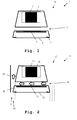
- the luminaire 1 comprises a luminaire housing 8, which comprises a first housing part 4 and a second housing part 2.
- the second housing part 2 is arranged above the first housing part 4 and separated by an air gap 7 thereof.
- the second housing part 2 includes a driver circuit 3 for operating the lamp 1, in particular for operating an LED module 5, which is arranged in the first housing part 4.
- the first housing part 4 also includes a viewing window 6, which is only covered transparent and thus allows light emission of the LED module downwards.
- the LED module 5 primarily heats up and, to a lesser extent, the driver circuit 3. This results in a heating of the air in the air gap 7. Since on both sides - ie left and right in Fig. 1 - The air gap 7 is an identical pressure, the air masses are equalized. There is no appreciable natural convection through the air gap 7 therethrough. It thus accumulates the hot air generated by the heated LED module 5 by the driver circuit 3 in the air gap 7. This leads to a heating of the lamp housing 8 and thus to a heating of the LED module 5 and the driver circuit. 3
- Fig. 2 is a first embodiment of the lamp 11 according to the invention including a light housing 12, also shown in a sectional view.
- the luminaire housing 12 includes a first housing part 30 and a second housing part 20.
- the second housing part 20 is arranged above the first housing part 30.
- the second housing part 20 includes a driver circuit 21.
- the first housing part 30 contains an LED module 31 and a transparent cover 32, which allows light to exit downwards.
- the first housing part 30 is separated from the second housing part 20 by an air gap 40.
- the luminaire housing 12 includes a first asymmetry element 50, which is arranged laterally next to the first housing part 30 and the second housing part 20.
- the asymmetric element 50 is arranged orthogonal to a plane described by the air gap 40.
- the asymmetrical element 50 has a first distance 41 from the first housing part 30. Furthermore, it has a second distance 42 to the second housing part 20.
- the luminaire housing 12 and the asymmetric element 50 form the luminaire arrangement according to the invention.
- no element is arranged on the side of the air gap 40 opposite the asymmetry element 50.
- no element is arranged within a distance corresponding to the first distance 41, and particularly advantageously within a distance corresponding to the second distance 42.
- Fig. 3 is a second embodiment of the lamp 11 according to the invention including a lamp housing 12, shown.
- the luminaire housing 12 additionally includes a second asymmetry element 51, which is arranged on the side of the air gap 40 opposite the first asymmetry element 50.
- the second asymmetry element 51 is arranged at a third distance 43 to the first housing part 30 and at a fourth distance 44 to the second housing part 20.
- the third distance 44 is preferably greater than the first distance 41.
- the fourth distance 44 is preferably greater than the second distance 42.
- the third distance 43 is greater than the second distance 42.
- the light housing 12 and the asymmetry elements 50, 51 thereby form the light assembly according to the invention.
- the opening or the distance between the second asymmetry element 51 and the luminaire housing 12 (or here the first housing part 30) is significantly larger than the opening or the distance between the first asymmetry element 50 and the luminaire housing 12 (FIG. or here the first housing part 30). Due to the asymmetry of the pressure conditions on the two sides of the lamp housing 12, as described with respect to the first embodiment described, an air flow through the opening between the second asymmetry member 51 and the lamp housing 12 (eg. Here the first housing part 30) into the air gap 40 causes. The warming / heated air there exits on the side of the first asymmetric element 50 and flows in the direction of the second housing part 20 or upwards; So in the sense of a natural convection. The air flow is indicated by arrows in Fig. 2 clarified.
- the second distance 42 is preferably still greater than the first distance 41.
- the third distance 43 is preferably smaller than the fourth distance 44th D.h.
- the first housing part 30 preferably has a greater width than the second housing part 20. This additionally promotes natural convection.
- the effect described can be equated with the effect of airfoils, which leads to a corresponding negative pressure and thus a suction effect in a predetermined direction due to a different path or an asymmetry in the support surface.
- the asymmetry is created by additional asymmetry elements 50, 51.
- the asymmetrical elements 50, 51 can also be used as part of the luminaire housing 12-that is to say one of the housing parts 20, 30-or of the luminaire overall housing accommodating the housing parts 20, 30 (not shown) and be provided as separate elements or integrally. It is likewise conceivable for the asymmetry to be brought about by elements of the luminous arrangement 12 arranged asymmetrically (for example laterally offset from each other). Particularly advantageous are asymmetrical configurations that do not affect the external appearance of the lamp.
- the asymmetrical elements 50, 51 are therefore not limited in their design and thus do not have to be present as plate-like elements, as shown in the figures.
- the luminaire can be present, for example, as suspended or surface-mounted luminaire. It is also conceivable that the luminaire is present as a recessed luminaire, with asymmetrical elements being laminated by a recessed ceiling receiving the recessed luminaire. Thus, for example, the transparent cover 32 or the light exit opening having side of the lamp or lamp assembly are aligned with a false ceiling.
- a non-orthogonal arrangement of the asymmetric elements 50, 51 with respect to the air gap 40 is also conceivable, provided that the natural convection is maintained.
- the invention is not limited to the illustrated embodiment. As already mentioned, different heat-generating components can be arranged within the housing parts and be cooled by the described luminaire housing. All features described above or features shown in the figures can be combined with each other in any advantageous manner within the scope of the invention. Also, the design of a luminaire arrangement or luminaire according to the invention is not limited by the invention as long as there is a corresponding air gap and the side of the same present asymmetry to produce a natural convection.
Landscapes
- Engineering & Computer Science (AREA)
- General Engineering & Computer Science (AREA)
- Microelectronics & Electronic Packaging (AREA)
- Arrangement Of Elements, Cooling, Sealing, Or The Like Of Lighting Devices (AREA)
Abstract
Description
- Die Erfindung betrifft eine Leuchtenanordnung und eine Leuchte bei welchen von Wärme-erzeugten Bauteilen erzeugte Wärme durch natürliche Konvektion abgeführt wird bzw. werden kann.
- Zwischen den Elementen einer Leuchte, beispielsweise einem Gehäuse, welches ein LED-Modul aufweist, und einem dahinterliegenden Gehäuse zur Aufnahme der Elektronik, besteht in der Regel ein Luftspalt, meist ein waagrechter Luftspalt. In diesem Luftspalt wird die von den LED-Modulen abgegebene Wärme an die Umgebungsluft abgegeben. Nachteilig bei herkömmlichen Leuchten ist jedoch, dass aufgrund der horizontalen Anordnung des Luftspalts kein Luftaustausch in dem Luftspalt stattfindet, da die sich beiderseitig des Luftspalts befindenden Massen ausgleichen und somit die Luft in dem Luftspalt im Wesentlichen steht. Dies führt zu einer kontinuierlichen Erhöhung der Temperatur innerhalb des Luftspalts und damit zu einer kontinuierlichen Erhöhung der Temperatur des LED-Moduls. Dies führt zu nachteiligen Auswirkungen auf die Funktion des LED-Moduls wie auch der Elektronik.
- Beispielsweise zeigt die deutsche Offenlegungsschrift
DE 10 2008 031 049 A1 eine Leuchte, welche zur Abfuhr der entstehenden Wärme einen dedizierten Kühlkörper benötigt, da die Geometrie der Leuchte lediglich eine suboptimale natürliche Konvektion erlaubt. - Der Erfindung liegt die Aufgabe zugrunde, eine Leuchtenanordnung und eine Leuchte zu schaffen, welche mit geringem Aufwand, insbesondere ohne Nutzung von aktiven Lüftern, eine hinreichend hohe Wärmeabfuhr gewährleisten. Die Aufgabe wird erfindungsgemäß durch die Merkmale der unabhängigen Ansprüche gelöst. Vorteilhafte Weiterbildungen sind Gegenstand der hierauf rückbezogenen Unteransprüche.
- Eine erfindungsgemäße Leuchtenanordnung beinhaltet ein Leuchtengehäuse mit einem ersten Gehäuseteil und einem zweiten Gehäuseteil, welche durch einen Luftspalt voneinander beabstandet sind. Der Luftspalt erstreckt sich dabei im Wesentlichen in einer Ebene. Darüber hinaus beinhaltet die Leuchtenanordnung ein erstes Asymmetrieelement, welches derart seitlich von dem Luftspalt beabstandet angeordnet ist, dass sich seitlich in Richtung der Ebene gesehen, ein erster Abstand des ersten Gehäuseteils zu dem ersten Asymmetrieelement ergibt. Das Leuchtengehäuse ist dabei derart ausgebildet, dass auf einer dem ersten Asymmetrieelement gegenüberliegenden Seite des Luftspalts kein Element innerhalb eines dem ersten Abstand entsprechenden Abstands angeordnet ist. Durch die asymmetrische Anordnung des Asymmetrieelements - also die gezielt herbeigeführte Asymmetrie bezüglich einander gegenüberliegender und vom Luftspalt seitlich beabstandeter "Seiten" in der Waagerechten gesehen - ist somit sichergestellt, dass sich bei einer Erwärmung der Luft in dem Luftspalt bei Betrieb der Leuchte ein Druckunterschied auf den gegenüberliegenden Seiten des Luftspaltes ergibt, der wiederum eine Luftströmung hin zu dem ersten Asymmetrieelement ergibt. Somit wird die natürliche Konvektion gefördert indem trotz vorzugsweise waagerechtem Luftspalt ein durch Erhöhung der Temperatur, also durch thermische Einflüsse, herbeigeführter Luftstrom durch Auftrieb erzeugt werden kann.
- Vorzugsweise ist das erste Asymmetrieelement derart angeordnet, dass sich seitlich in Richtung der Ebene gesehen, der erste Abstand als Abstand des ersten Gehäuseteils zu dem ersten Asymmetrieelement und ein zweiter Abstand des zweiten Gehäuseteils zu dem ersten Asymmetrieelement ergibt. Das Leuchtengehäuse ist dabei derart ausgebildet, dass auf einer dem ersten Asymmetrieelement gegenüberliegenden Seite des Luftspalts kein Element innerhalb des zweiten Abstands von dem zweiten Gehäuseteil angeordnet ist. Es ist somit sichergestellt, dass das Asymmetrieelement sowohl gegenüber dem ersten Gehäuseteil als auch gegenüber dem zweiten Gehäuseteil in einem geeigneten Abstand angeordnet ist, um die natürliche Konvektion zu fördern.
- Vorzugsweise ist der zweite Abstand dabei größer als der erste Abstand. Das erste Asymmetrieelement kann im Wesentlichen orthogonal zu der Ebene angeordnet sein. Auch diese Maßnahmen fördern weiter die natürliche Konvektion.
- Bevorzugt weist die Leuchtenanordnung ein zweites Asymmetrieelement auf, welches derart auf einer dem ersten Asymmetrieelement gegenüberliegenden Seite seitlich von dem Luftspalt beabstandet angeordnet ist, dass sich seitlich in Richtung der Ebene gesehen, ein dritter Abstand des Leuchtengehäuses zu dem zweiten Asymmetrieelement ergibt. Der dritte Abstand ist dabei größer als der erste Abstand. Sofern der zweite Abstand vorhanden ist, ist der dritte Abstand dabei größer als der zweite Abstand. So wird sichergestellt, dass Umgebungsluft durch den dritten Abstand in den Luftspalt strömt, dort erwärmt wird und auf Seite des ersten Abstands aus dem Luftspalt heraustritt.
- Vorzugsweise ist das zweite Asymmetrieelement derart angeordnet, sodass sich seitlich in Richtung der Ebene gesehen der dritte Abstand des ersten Gehäuseteils zu dem zweiten Asymmetrieelement und ein vierter Abstand des zweiten Gehäuseteils zu dem zweiten Asymmetrieelement ergibt. Auch durch diese Maßnahmen wird die natürliche Konvektion weiter gefördert.
- Bevorzugt ist der vierte Abstand größer als der dritte Abstand. Das zweite Asymmetrieelement kann im Wesentlichen orthogonal zu der Ebene angeordnet sein. So wird sichergestellt, dass Umgebungsluft auf Seiten des zweiten Asymmetrieelements durch den zweiten bzw. vierten Abstand in den Luftspalt hineinfließt und den Luftspalt auf Seiten des ersten Abstands bzw. dritten Abstands den Luftspalt verlässt nachdem sie im Luftspalt erwärmt wurde. Dies fördert die natürliche Konvektion zusätzlich.
- Eine erfindungsgemäße Leuchtenanordnung kann darüber hinaus ein Leuchtengesamtgehäuse aufweisen, in welchem das Leuchtengehäuse mit dem ersten Gehäuseteil und dem zweiten Gehäuseteil sowie die Asymmetrieelemente angeordnet sind. So kann die Leuchtenanordnung besonders effizient hergestellt werden. Ebenso kann ein Asymmetrieelement bereitgestellt werden, ohne in das Gesamterscheinungsbild der Leuchte einzugreifen.
- Vorzugsweise sind dabei das erste Asymmetrieelement und das zweite Asymmetrieelement als separate Elemente bereitgestellt oder integral wenigstens mit einem der Teile des Leuchtengehäuses und/oder, falls die Leuchtenanordnung ein Leuchtengesamtgehäuse aufweist, integral mit dem Leuchtengesamtgehäuse ausgebildet. Auch durch diese Maßnahmen kann eine besonders effiziente Fertigung der Leuchtenanordnung erreicht werden.
- Eine erfindungsgemäße Leuchte beinhaltet eine zuvor beschriebene Leuchtenanordnung. In wenigstens dem ersten Gehäuseteil sind bei einem Betrieb der Leuchte Wärme-erzeugende Bauteile angeordnet. Bei den Wärme-erzeugenden Bauteilen handelt es sich bevorzugt um Leuchtmittel, wie LEDs. So kann bei der erfindungsgemäßen Leuchte von den Wärme-erzeugenden Bauteilen abgegebene Wärme durch die gute natürliche Konvektion durch die erfindungsgemäße Leuchte einfach abgeführt werden.
- Bevorzugt ist dabei das erste Asymmetrieelement derart angeordnet, dass sich bei einem Betrieb der Leuchte durch Konvektion von durch die Wärme-erzeugenden Bauteile erzeugter Warmluft ein Luftstrom durch den Luftspalt in Richtung des ersten Asymmetrieelements einstellt. So wird eine besonders gute Kühlung der Wärme-erzeugenden Bauteile erreicht.
- Vorzugsweise weist die Leuchtenanordnung dabei ein zweites Asymmetrieelement auf. Das zweite Asymmetrieelement ist dabei derart angeordnet, dass sich bei einem Betrieb der Leuchte durch Konvektion von durch die Wärme-erzeugenden Bauteile erzeugter Warmluft ein Luftstrom durch den Luftspalt aus Richtung des zweiten Asymmetrieelements in Richtung des ersten Asymmetrieelements einstellt. So wird eine besonders gute natürliche Konvektion erreicht.
- Bevorzugt befinden sich in dem zweiten Gehäuseteil elektronische Bauteile zum Betrieb der Leuchte, insbesondere eine Treiberschaltung. So kann auch von der Treiberschaltung erzeugte Wärme günstig abgeführt werden.
- Nachfolgend wird die Erfindung anhand der Zeichnung, in der ein vorteilhaftes Ausführungsbeispiel der Erfindung dargestellt ist, beispielhaft beschrieben. In der Zeichnung zeigen:
- Fig. 1
- ein herkömmliches Leuchtgehäuse;
- Fig. 2
- ein erstes Ausführungsbeispiel der erfindungsgemäßen Leuchte beinhaltend ein erstes Ausführungsbeispiel der erfindungsgemäßen Leuchtenanordnung, und
- Fig. 3
- ein zweites Ausführungsbeispiel der erfindungsgemäßen Leuchte beinhaltend ein zweites Ausführungsbeispiel der erfindungsgemäßen Leuchtenanordnung.
- Zunächst wird anhand der
Fig. 1 der generelle Aufbau und die generelle Funktionsweise einer herkömmlichen Leuchte und eines herkömmlichen Leuchtengehäuses erläutert. Basierend aufFig. 1 wird zusätzlich die zugrunde liegende Problematik näher dargestellt. Anschließend wird anhand vonFig. 2 undFig. 3 auf den Aufbau und die Funktionsweise mehrerer Ausführungsbeispiele der erfindungsgemäßen Leuchte bzw. der erfindungsgemäßen Leuchtenanordnung eingegangen. Identische Elemente wurden in ähnlichen Abbildungen z.T. nicht wiederholt dargestellt und beschrieben. - In
Fig. 1 ist eine exemplarische Leuchte 1 dargestellt. In der hier gezeigten Ansicht wird ein Querschnitt durch eine längs erstreckte Leuchte gezeigt. Die Leuchte 1 umfasst dabei ein Leuchtengehäuse 8, welches ein erstes Gehäuseteil 4 und ein zweites Gehäuseteil 2 umfasst. Das zweite Gehäuseteil 2 ist dabei oberhalb des ersten Gehäuseteils 4 angeordnet und durch einen Luftspalt 7 von diesem getrennt. - Das zweite Gehäuseteil 2 beinhaltet dabei eine Treiberschaltung 3 zum Betrieb der Leuchte 1, insbesondere zum Betrieb eines LED-Moduls 5, welches in dem ersten Gehäuseteil 4 angeordnet ist. Das erste Gehäuseteil 4 beinhaltet darüber hinaus ein Sichtfenster 6, welches lediglich transparent abgedeckt ist und somit einen Lichtaustritt des LED-Moduls nach unten hin ermöglicht.
- Im Betrieb der Leuchte 1 erwärmt sich in erster Linie das LED-Modul 5 und darüber hinaus in geringerem Maße die Treiberschaltung 3. Es ergibt sich somit eine Erwärmung der Luft in dem Luftspalt 7. Da auf beiden Seiten - also links und rechts in
Fig. 1 - des Luftspalts 7 ein identischer Druck besteht, gleichen sich die Luftmassen aus. Es entsteht keine nennenswerte natürliche Konvektion durch den Luftspalt 7 hindurch. Es staut sich somit die von dem erwärmten LED-Modul 5 durch die Treiberschaltung 3 erzeugte Warmluft in dem Luftspalt 7. Dies führt zu einer Erwärmung des Leuchtengehäuses 8 und somit zu einer Erwärmung des LED-Moduls 5 und der Treiberschaltung 3. - In
Fig. 2 ist ein erstes Ausführungsbeispiel der erfindungsgemäßen Leuchte 11 beinhaltend ein Leuchtengehäuse 12, ebenfalls in einer Schnitt-Ansicht dargestellt. Das Leuchtengehäuse 12 beinhaltet dabei ein erstes Gehäuseteil 30 und ein zweites Gehäuseteil 20. Das zweite Gehäuseteil 20 ist dabei oberhalb des ersten Gehäuseteils 30 angeordnet. Das zweite Gehäuseteil 20 beinhaltet dabei eine Treiberschaltung 21. Das erste Gehäuseteil 30 beinhaltet dabei ein LED-Modul 31 und eine transparente Abdeckung 32, welche einen Lichtaustritt nach unten hin ermöglicht. Das erste Gehäuseteil 30 ist von dem zweiten Gehäuseteil 20 durch einen Luftspalt 40 getrennt. - Darüber hinaus beinhaltet das Leuchtengehäuse 12 ein erstes Asymmetrieelement 50, welches seitlich neben dem ersten Gehäuseteil 30 und dem zweiten Gehäuseteil 20 angeordnet ist. Das Asymmetrieelement 50 ist dabei orthogonal zu einer von dem Luftspalt 40 beschriebenen Ebene angeordnet. Das Asymmetrieelement 50 weist dabei einen ersten Abstand 41 zu dem ersten Gehäuseteil 30 auf. Weiterhin weist es einen zweiten Abstand 42 zu dem zweiten Gehäuseteil 20 auf. Das Leuchtengehäuse 12 und das Asymmetrieelement 50 bilden dabei die erfindungsgemäße Leuchtenanordnung.
- Deutlich erkennbar ist hier, dass auf der dem Asymmetrieelement 50 gegenüberliegenden Seite des Luftspalts 40 kein Element angeordnet ist. Insbesondere ist kein Element innerhalb eines dem ersten Abstand 41 entsprechenden Abstands und besonders vorteilhaft innerhalb eines dem zweiten Abstand 42 entsprechenden Abstand angeordnet. Es ergibt sich somit eine Asymmetrie der Druckverhältnisse auf den beiden Seiten des Leuchtengehäuses 12; niedriger Druck auf Seiten des Asymmetrieelements 50 und hoher Druck auf der dem Asymmetrieelement 50 gegenüberliegenden Seite des Luftspalts 7, so dass Luft von der den hohen Druck aufweisenden Seite zu der den niedrigen Druck aufweisenden Seite "gesogen" wird. D.h. es ergibt sich eine Luftströmung von dem Luftspalt 40 hin zu dem Asymmetrieelement 50 und in Richtung des zweiten Gehäuseteils 20, weg von dem ersten Gehäuseteil 30. Da auf der dem Asymmetrieelement 50 gegenüberliegenden Seite des Luftspalts 40 kein entsprechendes Element angeordnet ist, strömt nicht-erwärmte Umgebungsluft nach, um die wie zuvor beschrieben ausgetretene Luft im Luftspalt 40 zu ersetzen. Es ergibt sich somit eine gestärkte natürliche Konvektion durch den Luftspalt 40 hindurch. Die Luftströmung ist dabei durch Pfeile verdeutlicht. Diese Strömung sorgt für einen deutlich gesteigerten Wärmeabtransport gegenüber dem in
Fig. 1 dargestellten Leuchtengehäuse 8. - In
Fig. 3 ist ein zweites Ausführungsbeispiel der erfindungsgemäßen Leuchte 11 beinhaltend ein Leuchtengehäuse 12, dargestellt. Hier beinhaltet das Leuchtengehäuse 12 zusätzlich ein zweites Asymmetrieelement 51, welches auf der dem ersten Asymmetrieelement 50 gegenüberliegenden Seite des Luftspalts 40 angeordnet ist. Das zweite Asymmetrieelement 51 ist dabei in einem dritten Abstand 43 zu dem ersten Gehäuseteil 30 und in einem vierten Abstand 44 zu dem zweiten Gehäuseteil 20 angeordnet. Der dritte Abstand 44 ist dabei vorzugsweise größer als der erste Abstand 41. Der vierte Abstand 44 ist dabei vorzugsweise größer als der zweite Abstand 42. Vorzugsweise ist dabei der dritte Abstand 43 größer als der zweite Abstand 42. Das Leuchtengehäuse 12 und die Asymmetrieelemente 50, 51 bilden dabei die erfindungsgemäße Leuchtenanordnung. - Es wird somit sichergestellt, dass die Öffnung bzw. der Abstand zwischen dem zweiten Asymmetrieelement 51 und dem Leuchtengehäuse 12 (bzw. hier dem ersten Gehäuseteil 30) deutlich größer ist als die Öffnung bzw. der Abstand zwischen dem ersten Asymmetrieelement 50 und dem Leuchtengehäuse 12 (bzw. hier dem ersten Gehäuseteil 30). Aufgrund der Asymmetrie der Druckverhältnisse auf den beiden Seiten des Leuchtengehäuses 12 wird, wie auch bzgl. des ersten Ausführungsbeispiels beschrieben, ein Luftstrom durch die Öffnung zwischen dem zweiten Asymmetrieelement 51 und dem Leuchtengehäuse 12 (bspw. hier dem ersten Gehäuseteil 30) hinein in den Luftspalt 40 bewirkt. Die sich dort erwärmende/erwärmte Luft tritt auf Seiten des ersten Asymmetrieelements 50 aus und strömt in Richtung des zweiten Gehäuseteils 20 bzw. nach oben ab; also im Sinne einer natürlichen Konvektion. Die Luftströmung ist dabei durch Pfeile in
Fig. 2 verdeutlicht. - Der zweite Abstand 42 ist dabei vorzugsweise weiterhin größer als der erste Abstand 41. Der dritte Abstand 43 ist dabei vorzugsweise kleiner als der vierte Abstand 44. D.h. das erste Gehäuseteil 30 weist vorzugsweise eine größere Breite auf als das zweite Gehäuseteil 20. Dies fördert zusätzlich die natürliche Konvektion.
- Der beschriebene Effekt kann gleichgesetzt werden mit dem Effekt von Tragflächen, welche aufgrund einer unterschiedlichen Wegstrecke bzw. einer Asymmetrie in der Tragfläche zu einem entsprechenden Unterdruck und somit einer Sogwirkung in eine vorgegebene Richtung führt.
- In den zuvor dargestellten Ausführungsbeispielen wird die Asymmetrie durch zusätzliche Asymmetrieelemente 50, 51 erzeugt. Die Asymmetrieelemente 50, 51 können dabei auch als Teil des Leuchtengehäuses 12 - also eines der Gehäuseteile 20, 30 - oder eines die Gehäuseteile 20, 30 aufnehmenden Leuchtengesamtgehäuses (nicht gezeigt) ausgebildet sein und als separate Elemente oder integral vorgesehen sein. Ebenso ist es denkbar, dass die Asymmetrie durch asymmetrisch (bspw. seitlich zueinander versetzt) angeordnete Elemente der Leuchtenanordnung 12 selbst herbeigeführt wird. Insbesondere vorteilhaft sind asymmetrische Ausgestaltungen, die das äußerliche Erscheinungsbild der Leuchte nicht beeinflussen. Die Asymmetrieelemente 50, 51 sind daher auch nicht in ihrer Ausgestaltung beschränkt und müssen somit nicht, wie in den Figuren gezeigt, als plattenartige Elemente vorliegen.
- Die Leuchte kann beispielsweise als Pendel- oder Anbauleuchte vorliegen. Auch ist es denkbar, dass die Leuchte als Einbauleuchte vorliegt, wobei asymmetrische Elemente durch eine die Einbauleuchte aufnehmende Zwischendecke kaschiert sind. So kann beispielsweise die die transparente Abdeckung 32 bzw. die Lichtaustrittsöffnung aufweisende Seite der Leuchte bzw. Leuchtenanordnung mit einer Zwischendecke fluchten.
- Auch eine gegenüber dem Luftspalt 40 nicht-orthogonale Anordnung der Asymmetrieelemente 50, 51 ist denkbar, sofern die natürliche Konvektion aufrechterhalten bleibt.
- Die Erfindung ist nicht auf das dargestellte Ausführungsbeispiel beschränkt. Wie bereits erwähnt, können unterschiedliche Wärme-erzeugende Bauelemente innerhalb der Gehäuseteile angeordnet sein und durch das beschriebene Leuchtengehäuse gekühlt werden. Alle vorstehend beschriebenen Merkmale oder in den Figuren gezeigten Merkmale sind im Rahmen der Erfindung beliebig vorteilhaft miteinander kombinierbar. Auch ist das Design einer erfindungsgemäßen Leuchtenanordnung bzw. Leuchte nicht durch die Erfindung beschränkt, solange ein entsprechender Luftspalt sowie die seitlich desselben vorliegende Asymmetrie zur Erzeugung einer natürlichen Konvektion vorliegen.
Claims (14)
- Leuchtenanordnung aufweisend:ein Leuchtengehäuse (12) mit einem ersten Gehäuseteil (30) und einem zweiten Gehäuseteil (20), welche durch einen Luftspalt (40) voneinander beabstandet sind,wobei sich der Luftspalt (40) im Wesentlichen in einer Ebene erstreckt, undzumindest ein erstes Asymmetrieelement (50), welches derart seitlich von dem Luftspalt (40) beabstandet angeordnet ist, dass sich seitlich in Richtung der Ebene gesehen, ein erster Abstand (41) des Leuchtengehäuses (12) zu dem ersten Asymmetrieelement (50) ergibt,wobei das Leuchtengehäuse (12) derart ausgebildet ist, dass auf einer dem ersten Asymmetrieelement (50) gegenüberliegenden Seite des Luftspalts (40) kein Element innerhalb eines dem ersten Abstand (41) entsprechenden Abstand angeordnet ist.
- Leuchtenanordnung nach Anspruch 1,
wobei das erste Asymmetrieelement (50) derart angeordnet ist, dass sich seitlich in Richtung der Ebene gesehen, der erste Abstand (41) als Abstand des ersten Gehäuseteils (30) zu dem ersten Asymmetrieelement und ein zweiter Abstand (42) des zweiten Gehäuseteils (20) zu dem ersten Asymmetrieelement (50) ergibt, und wobei das Leuchtengehäuse (12) derart ausgebildet ist, dass auf einer dem ersten Asymmetrieelement (50) gegenüberliegenden Seite des Luftspalts (40) kein Element innerhalb des zweiten Abstands (42) von dem zweiten Gehäuseteil (30) angeordnet ist. - Leuchtenanordnung nach Anspruch 2,
wobei der zweite Abstand (42) größer ist als der erste Abstand (41). - Leuchtenanordnung nach einem der Ansprüche 1 bis 3,
wobei sich das erste Asymmetrieelement (50) im Wesentlichen orthogonal zu der Ebene erstreckt. - Leuchtenanordnung nach einem der Ansprüche 1 bis 4, aufweisend:ein zweites Asymmetrieelement (51), welches derart auf einer dem ersten Asymmetrieelement (50) gegenüberliegenden Seite seitlich von dem Luftspalt (40) beabstandet angeordnet ist, dass sich seitlich in Richtung der Ebene gesehen, ein dritter Abstand (43) des Leuchtengehäuses (12) zu dem zweiten Asymmetrieelement (51) ergibt,wobei der dritte Abstand (43) größer ist als der erste Abstand (41), und, wenn der zweite Abstand (42) vorhanden ist, der dritte Abstand (43) größer ist als der zweite Abstand (42).
- Leuchtenanordnung nach Anspruch 5,
wobei das zweite Asymmetrieelement (51) derart angeordnet ist, dass sich seitlich in Richtung der Ebene gesehen, der dritte Abstand (41) als Abstand des ersten Gehäuseteils (30) zu dem zweiten Asymmetrieelement (51) und ein vierter Abstand (44) des zweiten Gehäuseteils (20) zu dem zweiten Asymmetrieelement (51) ergibt. - Leuchtenanordnung nach Anspruch 6,
wobei der vierte Abstand (44) größer ist als der dritte Abstand (43). - Leuchtenanordnung nach einem der Ansprüche 5 bis 7,
wobei sich das zweite Asymmetrieelement (51) im Wesentlichen orthogonal zu der Ebene erstreckt. - Leuchtenanordnung nach einem der Ansprüche 1 bis 8, ferner aufweisend ein Leuchtengesamtgehäuse,
wobei das Leuchtengehäuse (12) mit dem ersten Gehäuseteil (30) und dem zweiten Gehäuseteil (20) sowie die Asymmetrieelemente (50, 51) in dem Leuchtengesamtgehäuse vorgesehen sind. - Leuchtenanordnung nach einem der Ansprüche 1 bis 9,
wobei das erste Asymmetrieelement und das zweite Asymmetrieelement als separate Elemente bereitgestellt oder integral wenigstens mit einem der Teile (20, 30) des Leuchtengehäuses (12) und/oder, falls die Leuchtenanordnung ein Leuchtengesamtgehäuse aufweist, integral mit dem Leuchtengesamtgehäuse ausgebildet sind. - Leuchte (11) aufweisend eine Leuchtenanordnung gemäß einem der Ansprüche 1 bis 10,
wobei wenigstens in dem ersten Gehäuseteil (30) bei einem Betrieb der Leuchte (11) Wärme-erzeugende Bauteile (21), insbesondere Leuchtmittel wie LEDs, vorgesehen sind. - Leuchte (11) gemäß Anspruch 11,
wobei das erste Asymmetrieelement (50) derart angeordnet ist, dass sich bei einem Betrieb der Leuchte (11) durch Konvektion von durch die Wärme-erzeugenden Bauteile (31) erzeugter Warmluft ein Luftstrom durch den Luftspalt (40) in Richtung des ersten Asymmetrieelements (50) einstellt. - Leuchte (11) gemäß Anspruch 11 oder 12, aufweisend eine Leuchtenanordnung gemäß einem der Ansprüche 5 bis 10,
wobei das zweite Asymmetrieelement (51) derart angeordnet ist, dass sich bei einem Betrieb der Leuchte (11) durch Konvektion von durch die Wärme-erzeugenden Bauteile (31) erzeugter Warmluft ein Luftstrom durch den Luftspalt (40) aus Richtung des zweiten Asymmetrieelements (51) in Richtung des ersten Asymmetrieelements (50) einstellt. - Leuchte (11) nach einem der Ansprüche 11 bis 13, wobei in dem zweiten Gehäuseteil (20) elektronische Bauteile (21) zum Betrieb der Leuchte, wie insbesondere eine Treiberschaltung, vorgesehen sind.
Applications Claiming Priority (1)
| Application Number | Priority Date | Filing Date | Title |
|---|---|---|---|
| DE202014103438.2U DE202014103438U1 (de) | 2014-07-25 | 2014-07-25 | Leuchtengehäuse mit natürlicher konvektiver Kühlung |
Publications (2)
| Publication Number | Publication Date |
|---|---|
| EP2977674A1 true EP2977674A1 (de) | 2016-01-27 |
| EP2977674B1 EP2977674B1 (de) | 2019-04-24 |
Family
ID=53717952
Family Applications (1)
| Application Number | Title | Priority Date | Filing Date |
|---|---|---|---|
| EP15178012.9A Not-in-force EP2977674B1 (de) | 2014-07-25 | 2015-07-23 | Leuchtengehäuse mit natürlicher konvektiver kühlung |
Country Status (3)
| Country | Link |
|---|---|
| EP (1) | EP2977674B1 (de) |
| AT (1) | AT14707U1 (de) |
| DE (1) | DE202014103438U1 (de) |
Families Citing this family (1)
| Publication number | Priority date | Publication date | Assignee | Title |
|---|---|---|---|---|
| NL2028173B1 (en) * | 2021-05-07 | 2022-11-24 | Schreder Sa | Modular lighting apparatus with cooling channel |
Citations (6)
| Publication number | Priority date | Publication date | Assignee | Title |
|---|---|---|---|---|
| US7431482B1 (en) * | 2005-06-21 | 2008-10-07 | W.A.C. Lighting Co. | Modular downlight assembly |
| DE102008031049A1 (de) | 2008-06-30 | 2009-12-31 | Lewa Gmbh | Vorrichtung zum Portionieren förderbarer Medien |
| CN201396640Y (zh) * | 2009-04-17 | 2010-02-03 | 天津市精唯光电科技有限公司 | 光源可更换的led筒灯 |
| DE102011008613A1 (de) * | 2010-01-21 | 2011-07-28 | Traxon Technologies Ltd. | Beleuchtungsvorrichtung |
| US8070328B1 (en) * | 2009-01-13 | 2011-12-06 | Koninkliljke Philips Electronics N.V. | LED downlight |
| US20120281409A1 (en) * | 2011-05-05 | 2012-11-08 | Ruud Lighting, Inc. | Lighting Fixture with Flow-Through Cooling |
Family Cites Families (5)
| Publication number | Priority date | Publication date | Assignee | Title |
|---|---|---|---|---|
| WO2007138505A1 (en) * | 2006-05-29 | 2007-12-06 | Koninklijke Philips Electronics N.V. | An assembly for use in a light alarm clock comprising a lamp and a casing |
| DE202009004252U1 (de) * | 2009-03-31 | 2010-05-27 | BÄRO GmbH & Co. KG | Leuchte |
| US8164237B2 (en) * | 2010-07-29 | 2012-04-24 | GEM-SUN Technologies Co., Ltd. | LED lamp with flow guide function |
| TW201243231A (en) * | 2011-04-27 | 2012-11-01 | Energyled Corp | Illuminator and heat removal device thereof |
| DE202011051579U1 (de) * | 2011-10-10 | 2013-01-17 | Zumtobel Lighting Gmbh | Kühlkörper-Anordnung für eine LED-Leuchte sowie LED-Leuchte |
-
2014
- 2014-07-25 DE DE202014103438.2U patent/DE202014103438U1/de not_active Expired - Lifetime
- 2014-09-29 AT ATGM346/2014U patent/AT14707U1/de not_active IP Right Cessation
-
2015
- 2015-07-23 EP EP15178012.9A patent/EP2977674B1/de not_active Not-in-force
Patent Citations (6)
| Publication number | Priority date | Publication date | Assignee | Title |
|---|---|---|---|---|
| US7431482B1 (en) * | 2005-06-21 | 2008-10-07 | W.A.C. Lighting Co. | Modular downlight assembly |
| DE102008031049A1 (de) | 2008-06-30 | 2009-12-31 | Lewa Gmbh | Vorrichtung zum Portionieren förderbarer Medien |
| US8070328B1 (en) * | 2009-01-13 | 2011-12-06 | Koninkliljke Philips Electronics N.V. | LED downlight |
| CN201396640Y (zh) * | 2009-04-17 | 2010-02-03 | 天津市精唯光电科技有限公司 | 光源可更换的led筒灯 |
| DE102011008613A1 (de) * | 2010-01-21 | 2011-07-28 | Traxon Technologies Ltd. | Beleuchtungsvorrichtung |
| US20120281409A1 (en) * | 2011-05-05 | 2012-11-08 | Ruud Lighting, Inc. | Lighting Fixture with Flow-Through Cooling |
Also Published As
| Publication number | Publication date |
|---|---|
| EP2977674B1 (de) | 2019-04-24 |
| AT14707U1 (de) | 2016-04-15 |
| DE202014103438U1 (de) | 2015-10-27 |
Similar Documents
| Publication | Publication Date | Title |
|---|---|---|
| EP3180562B1 (de) | Fahrzeugscheinwerfer | |
| DE102015221464B4 (de) | Hintergrundbeleuchtungsvorrichtung | |
| WO2011124356A1 (de) | Leuchtengehäuse | |
| DE202018101375U1 (de) | Elektronische Baugruppe mit einem Gehäuse mit Kühlrippen | |
| EP2320137A1 (de) | Kühlkörper für LED-Leuchte | |
| EP2977674B1 (de) | Leuchtengehäuse mit natürlicher konvektiver kühlung | |
| DE10326083A1 (de) | Rippenkonstruktion und Baugruppe mit einer solchen | |
| EP2711750B1 (de) | LED-Leuchte mit Lichtleiterplatte | |
| EP4226077B1 (de) | Beleuchtungsvorrichtung für einen kraftfahrzeugscheinwerfer | |
| DE102010042193A1 (de) | LED-Leuchte mit gebogenem Lichtabgebebereich | |
| DE102007053090B4 (de) | Kühlkörper und Kühlanordnung für elektrische Komponenten und Verfahren zur Herstellung eines Kühlkörpers und einer Kühlanordnung für elektrische Komponenten | |
| EP3746697B1 (de) | Lichterzeugungsanordnung und kraftfahrzeugleuchte | |
| DE202017102627U1 (de) | Tunnelleuchte | |
| DE10125189B4 (de) | Leuchtapparat mit Wärmeableitvorrichtung | |
| DE202016107013U1 (de) | Leuchteinheit, insbesondere für eine Schirmleuchte, und Leuchte, insbesondere Schirmleuchte, mit einer Leuchteinheit | |
| EP2982899A1 (de) | Flächige ausstellungsleuchte | |
| DE102008030353A1 (de) | Fahrzeugleuchte mit einem Wärme leitenden Kunststoff | |
| DE102011055234A1 (de) | Beleuchtungssystem für ein Kraftfahrzeug und Verfahren zur Unterstützung der natürlichen Luftzirkulation in einem Beleuchtungssystem | |
| WO2015021996A1 (de) | Leuchte | |
| EP2734777B1 (de) | Anordnung zur lichtabgabe | |
| DE102014005298A1 (de) | Verfahren zur Herstellung eines Leuchtmittels, Leuchtmittel und Beleuchtungssystem | |
| EP2581657B1 (de) | Kühlkörper-Anordnung für eine LED-Leuchte sowie LED-Leuchte | |
| DE202015104292U1 (de) | LED-Anordnung mit Pitch-Kompensation | |
| DE102004052348A1 (de) | Kraftfahrzeugleuchte | |
| DE102013113529A1 (de) | Scheinwerfer für ein Fahrzeug mit einer Kühlluftführung |
Legal Events
| Date | Code | Title | Description |
|---|---|---|---|
| PUAI | Public reference made under article 153(3) epc to a published international application that has entered the european phase |
Free format text: ORIGINAL CODE: 0009012 |
|
| AK | Designated contracting states |
Kind code of ref document: A1 Designated state(s): AL AT BE BG CH CY CZ DE DK EE ES FI FR GB GR HR HU IE IS IT LI LT LU LV MC MK MT NL NO PL PT RO RS SE SI SK SM TR |
|
| AX | Request for extension of the european patent |
Extension state: BA ME |
|
| 17P | Request for examination filed |
Effective date: 20160629 |
|
| RBV | Designated contracting states (corrected) |
Designated state(s): AL AT BE BG CH CY CZ DE DK EE ES FI FR GB GR HR HU IE IS IT LI LT LU LV MC MK MT NL NO PL PT RO RS SE SI SK SM TR |
|
| STAA | Information on the status of an ep patent application or granted ep patent |
Free format text: STATUS: EXAMINATION IS IN PROGRESS |
|
| 17Q | First examination report despatched |
Effective date: 20161128 |
|
| RIC1 | Information provided on ipc code assigned before grant |
Ipc: F21V 29/83 20150101ALI20181130BHEP Ipc: F21Y 115/10 20160101ALN20181130BHEP Ipc: F21V 15/01 20060101AFI20181130BHEP Ipc: F21V 23/00 20150101ALI20181130BHEP |
|
| GRAP | Despatch of communication of intention to grant a patent |
Free format text: ORIGINAL CODE: EPIDOSNIGR1 |
|
| STAA | Information on the status of an ep patent application or granted ep patent |
Free format text: STATUS: GRANT OF PATENT IS INTENDED |
|
| RIC1 | Information provided on ipc code assigned before grant |
Ipc: F21V 29/83 20150101ALI20181218BHEP Ipc: F21Y 115/10 20160101ALN20181218BHEP Ipc: F21V 15/01 20060101AFI20181218BHEP Ipc: F21V 23/00 20150101ALI20181218BHEP |
|
| INTG | Intention to grant announced |
Effective date: 20190122 |
|
| GRAS | Grant fee paid |
Free format text: ORIGINAL CODE: EPIDOSNIGR3 |
|
| GRAA | (expected) grant |
Free format text: ORIGINAL CODE: 0009210 |
|
| STAA | Information on the status of an ep patent application or granted ep patent |
Free format text: STATUS: THE PATENT HAS BEEN GRANTED |
|
| AK | Designated contracting states |
Kind code of ref document: B1 Designated state(s): AL AT BE BG CH CY CZ DE DK EE ES FI FR GB GR HR HU IE IS IT LI LT LU LV MC MK MT NL NO PL PT RO RS SE SI SK SM TR |
|
| REG | Reference to a national code |
Ref country code: GB Ref legal event code: FG4D Free format text: NOT ENGLISH |
|
| REG | Reference to a national code |
Ref country code: CH Ref legal event code: EP |
|
| REG | Reference to a national code |
Ref country code: AT Ref legal event code: REF Ref document number: 1124573 Country of ref document: AT Kind code of ref document: T Effective date: 20190515 Ref country code: IE Ref legal event code: FG4D Free format text: LANGUAGE OF EP DOCUMENT: GERMAN |
|
| REG | Reference to a national code |
Ref country code: DE Ref legal event code: R096 Ref document number: 502015008781 Country of ref document: DE |
|
| REG | Reference to a national code |
Ref country code: NL Ref legal event code: MP Effective date: 20190424 |
|
| REG | Reference to a national code |
Ref country code: LT Ref legal event code: MG4D |
|
| PG25 | Lapsed in a contracting state [announced via postgrant information from national office to epo] |
Ref country code: NL Free format text: LAPSE BECAUSE OF FAILURE TO SUBMIT A TRANSLATION OF THE DESCRIPTION OR TO PAY THE FEE WITHIN THE PRESCRIBED TIME-LIMIT Effective date: 20190424 |
|
| PG25 | Lapsed in a contracting state [announced via postgrant information from national office to epo] |
Ref country code: NO Free format text: LAPSE BECAUSE OF FAILURE TO SUBMIT A TRANSLATION OF THE DESCRIPTION OR TO PAY THE FEE WITHIN THE PRESCRIBED TIME-LIMIT Effective date: 20190724 Ref country code: LT Free format text: LAPSE BECAUSE OF FAILURE TO SUBMIT A TRANSLATION OF THE DESCRIPTION OR TO PAY THE FEE WITHIN THE PRESCRIBED TIME-LIMIT Effective date: 20190424 Ref country code: FI Free format text: LAPSE BECAUSE OF FAILURE TO SUBMIT A TRANSLATION OF THE DESCRIPTION OR TO PAY THE FEE WITHIN THE PRESCRIBED TIME-LIMIT Effective date: 20190424 Ref country code: SE Free format text: LAPSE BECAUSE OF FAILURE TO SUBMIT A TRANSLATION OF THE DESCRIPTION OR TO PAY THE FEE WITHIN THE PRESCRIBED TIME-LIMIT Effective date: 20190424 Ref country code: HR Free format text: LAPSE BECAUSE OF FAILURE TO SUBMIT A TRANSLATION OF THE DESCRIPTION OR TO PAY THE FEE WITHIN THE PRESCRIBED TIME-LIMIT Effective date: 20190424 Ref country code: AL Free format text: LAPSE BECAUSE OF FAILURE TO SUBMIT A TRANSLATION OF THE DESCRIPTION OR TO PAY THE FEE WITHIN THE PRESCRIBED TIME-LIMIT Effective date: 20190424 Ref country code: PT Free format text: LAPSE BECAUSE OF FAILURE TO SUBMIT A TRANSLATION OF THE DESCRIPTION OR TO PAY THE FEE WITHIN THE PRESCRIBED TIME-LIMIT Effective date: 20190824 Ref country code: ES Free format text: LAPSE BECAUSE OF FAILURE TO SUBMIT A TRANSLATION OF THE DESCRIPTION OR TO PAY THE FEE WITHIN THE PRESCRIBED TIME-LIMIT Effective date: 20190424 |
|
| PG25 | Lapsed in a contracting state [announced via postgrant information from national office to epo] |
Ref country code: BG Free format text: LAPSE BECAUSE OF FAILURE TO SUBMIT A TRANSLATION OF THE DESCRIPTION OR TO PAY THE FEE WITHIN THE PRESCRIBED TIME-LIMIT Effective date: 20190724 Ref country code: RS Free format text: LAPSE BECAUSE OF FAILURE TO SUBMIT A TRANSLATION OF THE DESCRIPTION OR TO PAY THE FEE WITHIN THE PRESCRIBED TIME-LIMIT Effective date: 20190424 Ref country code: PL Free format text: LAPSE BECAUSE OF FAILURE TO SUBMIT A TRANSLATION OF THE DESCRIPTION OR TO PAY THE FEE WITHIN THE PRESCRIBED TIME-LIMIT Effective date: 20190424 Ref country code: LV Free format text: LAPSE BECAUSE OF FAILURE TO SUBMIT A TRANSLATION OF THE DESCRIPTION OR TO PAY THE FEE WITHIN THE PRESCRIBED TIME-LIMIT Effective date: 20190424 Ref country code: GR Free format text: LAPSE BECAUSE OF FAILURE TO SUBMIT A TRANSLATION OF THE DESCRIPTION OR TO PAY THE FEE WITHIN THE PRESCRIBED TIME-LIMIT Effective date: 20190725 |
|
| PG25 | Lapsed in a contracting state [announced via postgrant information from national office to epo] |
Ref country code: IS Free format text: LAPSE BECAUSE OF FAILURE TO SUBMIT A TRANSLATION OF THE DESCRIPTION OR TO PAY THE FEE WITHIN THE PRESCRIBED TIME-LIMIT Effective date: 20190824 |
|
| REG | Reference to a national code |
Ref country code: DE Ref legal event code: R097 Ref document number: 502015008781 Country of ref document: DE |
|
| PG25 | Lapsed in a contracting state [announced via postgrant information from national office to epo] |
Ref country code: SK Free format text: LAPSE BECAUSE OF FAILURE TO SUBMIT A TRANSLATION OF THE DESCRIPTION OR TO PAY THE FEE WITHIN THE PRESCRIBED TIME-LIMIT Effective date: 20190424 Ref country code: EE Free format text: LAPSE BECAUSE OF FAILURE TO SUBMIT A TRANSLATION OF THE DESCRIPTION OR TO PAY THE FEE WITHIN THE PRESCRIBED TIME-LIMIT Effective date: 20190424 Ref country code: DK Free format text: LAPSE BECAUSE OF FAILURE TO SUBMIT A TRANSLATION OF THE DESCRIPTION OR TO PAY THE FEE WITHIN THE PRESCRIBED TIME-LIMIT Effective date: 20190424 Ref country code: RO Free format text: LAPSE BECAUSE OF FAILURE TO SUBMIT A TRANSLATION OF THE DESCRIPTION OR TO PAY THE FEE WITHIN THE PRESCRIBED TIME-LIMIT Effective date: 20190424 Ref country code: CZ Free format text: LAPSE BECAUSE OF FAILURE TO SUBMIT A TRANSLATION OF THE DESCRIPTION OR TO PAY THE FEE WITHIN THE PRESCRIBED TIME-LIMIT Effective date: 20190424 |
|
| PG25 | Lapsed in a contracting state [announced via postgrant information from national office to epo] |
Ref country code: MC Free format text: LAPSE BECAUSE OF FAILURE TO SUBMIT A TRANSLATION OF THE DESCRIPTION OR TO PAY THE FEE WITHIN THE PRESCRIBED TIME-LIMIT Effective date: 20190424 Ref country code: IT Free format text: LAPSE BECAUSE OF FAILURE TO SUBMIT A TRANSLATION OF THE DESCRIPTION OR TO PAY THE FEE WITHIN THE PRESCRIBED TIME-LIMIT Effective date: 20190424 Ref country code: SM Free format text: LAPSE BECAUSE OF FAILURE TO SUBMIT A TRANSLATION OF THE DESCRIPTION OR TO PAY THE FEE WITHIN THE PRESCRIBED TIME-LIMIT Effective date: 20190424 |
|
| PLBE | No opposition filed within time limit |
Free format text: ORIGINAL CODE: 0009261 |
|
| REG | Reference to a national code |
Ref country code: CH Ref legal event code: PL |
|
| STAA | Information on the status of an ep patent application or granted ep patent |
Free format text: STATUS: NO OPPOSITION FILED WITHIN TIME LIMIT |
|
| PG25 | Lapsed in a contracting state [announced via postgrant information from national office to epo] |
Ref country code: TR Free format text: LAPSE BECAUSE OF FAILURE TO SUBMIT A TRANSLATION OF THE DESCRIPTION OR TO PAY THE FEE WITHIN THE PRESCRIBED TIME-LIMIT Effective date: 20190424 |
|
| 26N | No opposition filed |
Effective date: 20200127 |
|
| REG | Reference to a national code |
Ref country code: BE Ref legal event code: MM Effective date: 20190731 |
|
| REG | Reference to a national code |
Ref country code: DE Ref legal event code: R084 Ref document number: 502015008781 Country of ref document: DE |
|
| PG25 | Lapsed in a contracting state [announced via postgrant information from national office to epo] |
Ref country code: BE Free format text: LAPSE BECAUSE OF NON-PAYMENT OF DUE FEES Effective date: 20190731 Ref country code: LU Free format text: LAPSE BECAUSE OF NON-PAYMENT OF DUE FEES Effective date: 20190723 Ref country code: SI Free format text: LAPSE BECAUSE OF FAILURE TO SUBMIT A TRANSLATION OF THE DESCRIPTION OR TO PAY THE FEE WITHIN THE PRESCRIBED TIME-LIMIT Effective date: 20190424 Ref country code: LI Free format text: LAPSE BECAUSE OF NON-PAYMENT OF DUE FEES Effective date: 20190731 Ref country code: CH Free format text: LAPSE BECAUSE OF NON-PAYMENT OF DUE FEES Effective date: 20190731 |
|
| PG25 | Lapsed in a contracting state [announced via postgrant information from national office to epo] |
Ref country code: IE Free format text: LAPSE BECAUSE OF NON-PAYMENT OF DUE FEES Effective date: 20190723 |
|
| PG25 | Lapsed in a contracting state [announced via postgrant information from national office to epo] |
Ref country code: CY Free format text: LAPSE BECAUSE OF FAILURE TO SUBMIT A TRANSLATION OF THE DESCRIPTION OR TO PAY THE FEE WITHIN THE PRESCRIBED TIME-LIMIT Effective date: 20190424 |
|
| PG25 | Lapsed in a contracting state [announced via postgrant information from national office to epo] |
Ref country code: MT Free format text: LAPSE BECAUSE OF FAILURE TO SUBMIT A TRANSLATION OF THE DESCRIPTION OR TO PAY THE FEE WITHIN THE PRESCRIBED TIME-LIMIT Effective date: 20190424 Ref country code: HU Free format text: LAPSE BECAUSE OF FAILURE TO SUBMIT A TRANSLATION OF THE DESCRIPTION OR TO PAY THE FEE WITHIN THE PRESCRIBED TIME-LIMIT; INVALID AB INITIO Effective date: 20150723 |
|
| REG | Reference to a national code |
Ref country code: AT Ref legal event code: MM01 Ref document number: 1124573 Country of ref document: AT Kind code of ref document: T Effective date: 20200723 |
|
| PG25 | Lapsed in a contracting state [announced via postgrant information from national office to epo] |
Ref country code: AT Free format text: LAPSE BECAUSE OF NON-PAYMENT OF DUE FEES Effective date: 20200723 |
|
| PG25 | Lapsed in a contracting state [announced via postgrant information from national office to epo] |
Ref country code: MK Free format text: LAPSE BECAUSE OF FAILURE TO SUBMIT A TRANSLATION OF THE DESCRIPTION OR TO PAY THE FEE WITHIN THE PRESCRIBED TIME-LIMIT Effective date: 20190424 |
|
| P01 | Opt-out of the competence of the unified patent court (upc) registered |
Effective date: 20230530 |
|
| PGFP | Annual fee paid to national office [announced via postgrant information from national office to epo] |
Ref country code: GB Payment date: 20230725 Year of fee payment: 9 |
|
| PGFP | Annual fee paid to national office [announced via postgrant information from national office to epo] |
Ref country code: FR Payment date: 20230725 Year of fee payment: 9 |
|
| PGFP | Annual fee paid to national office [announced via postgrant information from national office to epo] |
Ref country code: DE Payment date: 20240730 Year of fee payment: 10 |
|
| GBPC | Gb: european patent ceased through non-payment of renewal fee |
Effective date: 20240723 |
|
| PG25 | Lapsed in a contracting state [announced via postgrant information from national office to epo] |
Ref country code: FR Free format text: LAPSE BECAUSE OF NON-PAYMENT OF DUE FEES Effective date: 20240731 |
|
| PG25 | Lapsed in a contracting state [announced via postgrant information from national office to epo] |
Ref country code: GB Free format text: LAPSE BECAUSE OF NON-PAYMENT OF DUE FEES Effective date: 20240723 |
|
| REG | Reference to a national code |
Ref country code: DE Ref legal event code: R119 Ref document number: 502015008781 Country of ref document: DE |
|
| PG25 | Lapsed in a contracting state [announced via postgrant information from national office to epo] |
Ref country code: DE Free format text: LAPSE BECAUSE OF NON-PAYMENT OF DUE FEES Effective date: 20260203 |