EP2977580A1 - Gasket - Google Patents
Gasket Download PDFInfo
- Publication number
- EP2977580A1 EP2977580A1 EP15178201.8A EP15178201A EP2977580A1 EP 2977580 A1 EP2977580 A1 EP 2977580A1 EP 15178201 A EP15178201 A EP 15178201A EP 2977580 A1 EP2977580 A1 EP 2977580A1
- Authority
- EP
- European Patent Office
- Prior art keywords
- gasket
- flange
- exhaust pipe
- sealing portion
- sealing
- Prior art date
- Legal status (The legal status is an assumption and is not a legal conclusion. Google has not performed a legal analysis and makes no representation as to the accuracy of the status listed.)
- Granted
Links
Images



Classifications
-
- F—MECHANICAL ENGINEERING; LIGHTING; HEATING; WEAPONS; BLASTING
- F16—ENGINEERING ELEMENTS AND UNITS; GENERAL MEASURES FOR PRODUCING AND MAINTAINING EFFECTIVE FUNCTIONING OF MACHINES OR INSTALLATIONS; THERMAL INSULATION IN GENERAL
- F16J—PISTONS; CYLINDERS; SEALINGS
- F16J15/00—Sealings
- F16J15/02—Sealings between relatively-stationary surfaces
- F16J15/06—Sealings between relatively-stationary surfaces with solid packing compressed between sealing surfaces
- F16J15/062—Sealings between relatively-stationary surfaces with solid packing compressed between sealing surfaces characterised by the geometry of the seat
-
- F—MECHANICAL ENGINEERING; LIGHTING; HEATING; WEAPONS; BLASTING
- F16—ENGINEERING ELEMENTS AND UNITS; GENERAL MEASURES FOR PRODUCING AND MAINTAINING EFFECTIVE FUNCTIONING OF MACHINES OR INSTALLATIONS; THERMAL INSULATION IN GENERAL
- F16L—PIPES; JOINTS OR FITTINGS FOR PIPES; SUPPORTS FOR PIPES, CABLES OR PROTECTIVE TUBING; MEANS FOR THERMAL INSULATION IN GENERAL
- F16L23/00—Flanged joints
- F16L23/16—Flanged joints characterised by the sealing means
- F16L23/18—Flanged joints characterised by the sealing means the sealing means being rings
-
- F—MECHANICAL ENGINEERING; LIGHTING; HEATING; WEAPONS; BLASTING
- F01—MACHINES OR ENGINES IN GENERAL; ENGINE PLANTS IN GENERAL; STEAM ENGINES
- F01N—GAS-FLOW SILENCERS OR EXHAUST APPARATUS FOR MACHINES OR ENGINES IN GENERAL; GAS-FLOW SILENCERS OR EXHAUST APPARATUS FOR INTERNAL-COMBUSTION ENGINES
- F01N13/00—Exhaust or silencing apparatus characterised by constructional features
- F01N13/08—Other arrangements or adaptations of exhaust conduits
-
- F—MECHANICAL ENGINEERING; LIGHTING; HEATING; WEAPONS; BLASTING
- F01—MACHINES OR ENGINES IN GENERAL; ENGINE PLANTS IN GENERAL; STEAM ENGINES
- F01N—GAS-FLOW SILENCERS OR EXHAUST APPARATUS FOR MACHINES OR ENGINES IN GENERAL; GAS-FLOW SILENCERS OR EXHAUST APPARATUS FOR INTERNAL-COMBUSTION ENGINES
- F01N13/00—Exhaust or silencing apparatus characterised by constructional features
- F01N13/18—Construction facilitating manufacture, assembly, or disassembly
- F01N13/1805—Fixing exhaust manifolds, exhaust pipes or pipe sections to each other, to engine or to vehicle body
-
- F—MECHANICAL ENGINEERING; LIGHTING; HEATING; WEAPONS; BLASTING
- F01—MACHINES OR ENGINES IN GENERAL; ENGINE PLANTS IN GENERAL; STEAM ENGINES
- F01N—GAS-FLOW SILENCERS OR EXHAUST APPARATUS FOR MACHINES OR ENGINES IN GENERAL; GAS-FLOW SILENCERS OR EXHAUST APPARATUS FOR INTERNAL-COMBUSTION ENGINES
- F01N13/00—Exhaust or silencing apparatus characterised by constructional features
- F01N13/18—Construction facilitating manufacture, assembly, or disassembly
- F01N13/1838—Construction facilitating manufacture, assembly, or disassembly characterised by the type of connection between parts of exhaust or silencing apparatus, e.g. between housing and tubes, between tubes and baffles
- F01N13/1844—Mechanical joints
-
- F—MECHANICAL ENGINEERING; LIGHTING; HEATING; WEAPONS; BLASTING
- F16—ENGINEERING ELEMENTS AND UNITS; GENERAL MEASURES FOR PRODUCING AND MAINTAINING EFFECTIVE FUNCTIONING OF MACHINES OR INSTALLATIONS; THERMAL INSULATION IN GENERAL
- F16J—PISTONS; CYLINDERS; SEALINGS
- F16J15/00—Sealings
- F16J15/02—Sealings between relatively-stationary surfaces
- F16J15/06—Sealings between relatively-stationary surfaces with solid packing compressed between sealing surfaces
- F16J15/10—Sealings between relatively-stationary surfaces with solid packing compressed between sealing surfaces with non-metallic packing
- F16J15/102—Sealings between relatively-stationary surfaces with solid packing compressed between sealing surfaces with non-metallic packing characterised by material
-
- F—MECHANICAL ENGINEERING; LIGHTING; HEATING; WEAPONS; BLASTING
- F16—ENGINEERING ELEMENTS AND UNITS; GENERAL MEASURES FOR PRODUCING AND MAINTAINING EFFECTIVE FUNCTIONING OF MACHINES OR INSTALLATIONS; THERMAL INSULATION IN GENERAL
- F16J—PISTONS; CYLINDERS; SEALINGS
- F16J15/00—Sealings
- F16J15/02—Sealings between relatively-stationary surfaces
- F16J15/06—Sealings between relatively-stationary surfaces with solid packing compressed between sealing surfaces
- F16J15/10—Sealings between relatively-stationary surfaces with solid packing compressed between sealing surfaces with non-metallic packing
- F16J15/12—Sealings between relatively-stationary surfaces with solid packing compressed between sealing surfaces with non-metallic packing with metal reinforcement or covering
- F16J15/121—Sealings between relatively-stationary surfaces with solid packing compressed between sealing surfaces with non-metallic packing with metal reinforcement or covering with metal reinforcement
-
- F—MECHANICAL ENGINEERING; LIGHTING; HEATING; WEAPONS; BLASTING
- F16—ENGINEERING ELEMENTS AND UNITS; GENERAL MEASURES FOR PRODUCING AND MAINTAINING EFFECTIVE FUNCTIONING OF MACHINES OR INSTALLATIONS; THERMAL INSULATION IN GENERAL
- F16L—PIPES; JOINTS OR FITTINGS FOR PIPES; SUPPORTS FOR PIPES, CABLES OR PROTECTIVE TUBING; MEANS FOR THERMAL INSULATION IN GENERAL
- F16L23/00—Flanged joints
- F16L23/16—Flanged joints characterised by the sealing means
- F16L23/162—Flanged joints characterised by the sealing means the pipe ends abutting each other
-
- F—MECHANICAL ENGINEERING; LIGHTING; HEATING; WEAPONS; BLASTING
- F16—ENGINEERING ELEMENTS AND UNITS; GENERAL MEASURES FOR PRODUCING AND MAINTAINING EFFECTIVE FUNCTIONING OF MACHINES OR INSTALLATIONS; THERMAL INSULATION IN GENERAL
- F16L—PIPES; JOINTS OR FITTINGS FOR PIPES; SUPPORTS FOR PIPES, CABLES OR PROTECTIVE TUBING; MEANS FOR THERMAL INSULATION IN GENERAL
- F16L23/00—Flanged joints
- F16L23/16—Flanged joints characterised by the sealing means
- F16L23/18—Flanged joints characterised by the sealing means the sealing means being rings
- F16L23/22—Flanged joints characterised by the sealing means the sealing means being rings made exclusively of a material other than metal
-
- F—MECHANICAL ENGINEERING; LIGHTING; HEATING; WEAPONS; BLASTING
- F16—ENGINEERING ELEMENTS AND UNITS; GENERAL MEASURES FOR PRODUCING AND MAINTAINING EFFECTIVE FUNCTIONING OF MACHINES OR INSTALLATIONS; THERMAL INSULATION IN GENERAL
- F16L—PIPES; JOINTS OR FITTINGS FOR PIPES; SUPPORTS FOR PIPES, CABLES OR PROTECTIVE TUBING; MEANS FOR THERMAL INSULATION IN GENERAL
- F16L25/00—Construction or details of pipe joints not provided for in, or of interest apart from, groups F16L13/00 - F16L23/00
- F16L25/12—Joints for pipes being spaced apart axially
Definitions
- the present invention relates to a gasket to be used in a joint for exhaust pipes of an automobile or the like.
- a seal member which is disclosed in Patent Literature 1 is known as a seal member (gasket) that is to be interposed between an upstream exhaust pipe and a downstream exhaust pipe.
- the seal member is interposed between a first flange of the upstream exhaust pipe and a second flange of the downstream exhaust pipe in order to seal the gap between end portions of the upstream and downstream exhaust pipes.
- the seal member is configured by using expanded graphite and a metal mesh, and includes a first sealing surface and a second sealing surface.
- the first sealing surface is configured as a convex spheroidal surface which is to butt slidably against a concave spheroidal sealing surface disposed on the first flange.
- the second sealing surface is configured as a convex spheroidal surface which is to butt slidably against a concave spheroidal sealing surface disposed on the second flange.
- the gasket has the configuration where the first and second sealing surfaces having a convex spheroidal shape simply butt against the concave spheroidal sealing surfaces of the corresponding flanges, respectively, and therefore cannot ensure a high sealing property between the first and second flanges. Namely, there is room for improvement in the sealing property of a gasket.
- Patent Literature 1 Japanese Patent Application Laid-Open No. 2004-76692
- the invention has been conducted in view of the above-discussed circumstances. It is an object of the invention to provide a gasket in which a high sealing property can be certainly ensured.
- a first mode of the invention provides a gasket which is annular, which is to be interposed between a first flange of a first exhaust pipe and a second flange of a second exhaust pipe in a state where the gasket is fitted onto an end portion of the first exhaust pipe, in order to seal a gap between an end portion of the first exhaust pipe and an end portion of the second exhaust pipe, the gasket being configured by using an expanded graphite tape and a metal mesh member, wherein the gasket includes: a first sealing portion having: a first butting surface having a tapered shape corresponding to a tapered shape of a first tapered inner circumferential surface of the first flange in which a diameter is gradually increased as proceeding toward the second flange; and a first projecting portion which is projectable toward the first tapered inner circumferential surface as compared with the first butting surface, the first sealing portion being formed in a radially outer side so as to allow the first butting surface and the first projecting portion to butt against the first tapered inner circumferential
- the whole first sealing portion when sealing is performed by using the gasket, the whole first sealing portion is pressed against the first tapered inner circumferential surface of the first flange which is opposed to the first sealing portion, to cause the first projecting portion to collapse, whereby the contact surface pressure between the first sealing portion and the first flange can be increased.
- the whole second sealing portion is pressed by the second tapered inner circumferential surface of the second flange which is opposed to the second sealing portion, to cause the second projecting portion to collapse, whereby the contact surface pressure between the second sealing portion and the second flange can be increased. Therefore, a high sealing property can be ensured between the first and second flanges.
- the gasket of the first mode further includes an outer circumferential portion which is formed between the first sealing portion and the second sealing portion with respect to an axial direction, and the first sealing portion and the second sealing portion are formed into a shape which is symmetrical across the outer circumferential portion.
- the gasket which is interposed between the first and second flanges it is possible to enable the gasket which is interposed between the first and second flanges, to more certainly exert a high sealing property irrespective of the direction of the gasket.
- the gasket is to be fitted onto the first exhaust pipe, moreover, it is not necessary to consider the direction of the gasket, and hence the workability can be improved.
- the gasket of the first or second mode further includes an exposed portion which is disposed in a radially inner side of the second sealing portion to be exposed to interiors of the first exhaust pipe and the second exhaust pipe, and metal wires of the metal mesh member are concentrically disposed in the exposed portion.
- the contact surface pressure of the second butting surface of the second sealing portion with respect to the tapered inner circumferential surface of the second flange can be maintained at a predetermined value, and reduction of the sealing property of the gasket can be suppressed.
- the metal wires of the metal mesh member can cause the expanded graphite portion of the expanded graphite tape to hardly contact with the exhaust gas flowing through the interiors (exhaust gas flow path) of the first and second exhaust pipes. Therefore, deterioration of the expanded graphite portion due to contact with the exhaust gas can be suppressed, and the durability of the gasket can be improved.
- Fig. 1 is a sectional view of a joint 10 in which a gasket 1 of an embodiment of the invention is used.
- a case where the gasket 1 is applied to the joint 10 as shown in Fig. 1 will be exemplarily described.
- the gasket 1 is used in the joint 10 for an exhaust pipe of an automobile or the like.
- the exhaust pipe has a first exhaust pipe 11 which is connected to an engine of the automobile or the like, and which is on the upstream side, and a second exhaust pipe 12 which is located downstream from the first exhaust pipe 11 in the flow direction of the exhaust gas.
- Each of the first exhaust pipe 11 and the second exhaust pipe 12 is configured by a cylindrical steel pipe.
- the exhaust pipes are coupled to each other through the joint 10 so as to have the same axis 13.
- the joint 10 is used for connecting the exhaust gas flow direction downstream end portion (tip end portion) 15 of the first exhaust pipe 11 with the exhaust gas flow direction upstream end portion (basal end portion) 16 of the second exhaust pipe 12 which is opposed thereto via a predetermined gap, and disposed between the end portions 15, 16.
- the joint 10 includes a first flange 21, a second flange 22, the gasket 1, and a press contacting mechanism 23.
- the first flange 21 is disposed on the outer circumference of the tip end portion 15 of the first exhaust pipe 11.
- the first flange 21 is formed by a sheet metal member, and has a first flange surface 25.
- the first flange 21 is disposed so as to be projected from the outer circumferential surface of the tip end portion 15 of the first exhaust pipe 11 toward the radially outer side in a state where the first flange surface 25 is directed to the downstream side in the flow direction of the exhaust gas.
- the first flange 21 has a first cylindrical portion 26, a first tapered portion 27, and a first flange portion 28.
- the first cylindrical portion 26 is fitted onto the tip end portion 15 of the first exhaust pipe 11, and fixed thereto by welding or the like.
- the first tapered portion 27 is extended from the first cylindrical portion 26 toward the radially outer side.
- the first flange portion 28 is extended from the first tapered portion 27 toward the radially outer side.
- the first tapered portion 27 is formed into a tapered shape in which the diameter is gradually increased as proceeding from the first cylindrical portion 26 toward the exhaust gas flow direction downstream side (side of the second flange 22).
- the first tapered portion 27 has a first tapered inner circumferential surface 27a which constitutes a part of the first flange surface 25, on the radially inner side (see Fig. 6 ), and is formed so that the first tapered inner circumferential surface 27a can be in contact with a part (first sealing portion 51 which will be described later) of the gasket 1.
- the second flange 22 is disposed on the outer circumference of the basal end portion 16 of the second exhaust pipe 12.
- the second flange 22 is formed by a sheet metal member, and has a second flange surface 35.
- the second flange 22 is disposed so as to be projected from the outer circumferential surface of the basal end portion 16 of the second exhaust pipe 12 toward the radially outer side in a state where the second flange surface 35 is directed to the upstream side in the flow direction of the exhaust gas in order to cause the second flange surface 35 to be opposed to the first flange surface 25 of the first flange 21.
- the second flange 22 has a second cylindrical portion 36, a second tapered portion 37, and a second flange portion 38.
- the second cylindrical portion 36 is fitted onto the basal end portion 16 of the second exhaust pipe 12, and fixed thereto by welding or the like.
- the second tapered portion 37 is extended from the second cylindrical portion 36 toward the radially outer side.
- the second flange portion 38 is extended from the second tapered portion 37 toward the radially outer side.
- the second tapered portion 37 is disposed upstream (on the side of the first flange 21) in the exhaust gas flow direction from the basal end portion 16 of the second exhaust pipe 12, and formed into a tapered shape in which the diameter is gradually increased as proceeding from the second cylindrical portion 36 toward the exhaust gas flow direction upstream side.
- the second tapered portion 37 has a second tapered inner circumferential surface 37a which constitutes a part of the second flange surface 35, on the radially inner side (see Fig. 7 ), and is formed so that the second tapered inner circumferential surface 37a can be in contact with a part (second sealing portion 52 which will be described later) of the gasket 1.
- the gasket 1 is an annular member, and, in order to seal the gap between the tip end portion 15 of the first exhaust pipe 11 and the basal end portion 16 of the second exhaust pipe 12, interposed between the first and second flanges 21, 22 of the first and second exhaust pipes 11, 22 which are opposed to each other, in a state where the gasket is fitted onto the first exhaust pipe 11.
- the gasket 1 has a circular annular shape, and is closely fitted onto a portion of the first exhaust pipe 11 which is downstream from the first flange 21 in the flow direction of the exhaust gas, so as to have the same axis 13.
- the press contacting mechanism 23 is configured so that the first flange 21 and the second flange 22 can be fasteningly connected to each other, thereby making the radially outer portions of the flanges 21, 22 to close to each other in the state where the gasket 1 is interposed between the flanges 21, 22.
- the press contacting mechanism 23 has bolts 45 and nuts 46, and is configured so as to enable the radially outer portion of the first flange 21 to press contact with that of the second flange 22, thereby preventing the gasket 1 from being exposed to the outside of the joint 10.
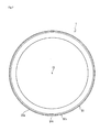
- Fig. 2 is a front view of the gasket 1
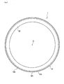
- Fig. 3 is a back view of the gasket 1
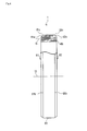
- Fig. 4 is a partially sectional side view of the gasket 1
- Fig. 5 shows materials of the gasket
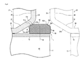
- Fig. 6 is a partial enlarged view showing a state where the gasket 1 has not yet been applied to the joint 10
- Fig. 7 is a partial enlarged view showing a state where the gasket 1 has been applied to the joint 10.
- the gasket 1 includes the first sealing portion 51 and the second sealing portion 52.
- the gasket 1 is configured by using an expanded graphite tape 56 and a metal mesh member 57.
- illustration of the expanded graphite tape 56 and the metal mesh member 57 (metal wires 58) is appropriately omitted except Fig. 5 and parts Figs. 6 and 7 .
- the gasket 1 has a configuration where a composite tape 59 in which the expanded graphite tape 56 is enclosed by the metal mesh member 57 is produced by applying a predetermined knitting method such as a loop forming knitting method to the metal wires 58 such as stainless steel wires around the expanded graphite tape 56 (see Fig. 5 ), the composite tape 59 is spirally wound a plurality of times, and the wound tape is compression molded, thereby forming the first sealing portion 51 and the second sealing portion 52.
- a predetermined knitting method such as a loop forming knitting method
- the composite tape 59 is spirally wound a plurality of times, and the wound tape is compression molded, thereby forming the first sealing portion 51 and the second sealing portion 52.
- the first sealing portion 51 has a first butting surface 51a and a first projecting portion 51b, and is formed in the radially outer side of the gasket 1 so that the first butting surface 51a and the first projecting portion 51b can butt against the first tapered inner circumferential surface 27a of the first flange 21.
- the first sealing portion 51 is disposed in an opposing portion of one side in the direction of the axis 13 of the gasket 1. When the gasket 1 is applied to the joint 10, the opposing portion is opposed to the first tapered inner circumferential surface 27a of the first flange 21.
- the first butting surface 51a is formed into a tapered shape corresponding to the tapered shape of the first tapered inner circumferential surface 27a of the first tapered portion 27 in which the diameter is gradually increased as proceeding toward the second flange 22 (from the upstream side in the exhaust gas flow direction toward the downstream side in the exhaust gas flow direction). Specifically, an end portion which is in the radially outer side of the gasket 1, and which is on one side in the direction of the axis 13 is notched away, whereby the first butting surface 51a is formed into a tapered surface in which the diameter is gradually increased as proceeding from the upstream side in the exhaust gas flow direction toward the downstream side in the exhaust gas flow direction.
- the first projecting portion 51b can be projected toward the first tapered inner circumferential surface 27a as compared with the first butting surface 51a.
- the first projecting portion 51b is placed downstream from the first butting surface 51a in the exhaust gas flow direction (on the inner side in the direction of the axis 13).
- the first projecting portion 51b has a first projecting end portion 51c which is formed into a pointed shape, and which is located radially outside the first butting surface 51a.
- the first projecting portion 51b is disposed so that, in accordance with relative movement of the first flange 21, the first projecting end portion 51c begins to butt against the opposing first tapered inner circumferential surface 27a.
- the first butting surface 51a is placed radially outside the centerline 61 of the radial thickness of the gasket 1.
- the first projecting portion 51b is continuous to the outer circumferential portion 63 of the gasket 1 in addition to the first butting surface 51a, and placed so that the first projecting end portion 51c is located on the outer circumferential surface of the gasket 1.
- the first sealing portion 51 has the configuration where, when the first and second flanges 21, 22 which are opposed to each other are fastened together by the function of the press contacting mechanism 23, the gasket 1 interposed between the flanges 21, 22 is pressed against the first flange 21, whereby the gasket is pressed to be compression deformed while the first butting surface 51a and the first projecting portion 51b butt against the first tapered inner circumferential surface 27a of the first flange 21.
- the second sealing portion 52 has a second butting surface 52a and a second projecting portion 52b, and is formed in the radially outer side of the gasket 1 so that the second butting surface 52a and the second projecting portion 52b can butt against the second tapered inner circumferential surface 37a of the second flange 22.
- the second sealing portion 52 is disposed in an opposing portion of the other side in the direction of the axis 13 of the gasket 1. When the gasket 1 is applied to the joint 10, the opposing portion is opposed to the second tapered inner circumferential surface 37a of the second flange 22.
- the second butting surface 52a is formed into a tapered shape corresponding to the tapered shape of the second tapered inner circumferential surface 37a of the second tapered portion 37 in which the diameter is gradually increased as proceeding toward the first flange 21 (from the downstream side in the exhaust gas flow direction toward the upstream side in the exhaust gas flow direction). Specifically, an end portion which is in the radially outer side of the gasket 1, and which is on the other side in the direction of the axis 13 is notched away, whereby the second butting surface 52a is formed into a tapered surface in which the diameter is gradually increased as proceeding from the downstream side in the exhaust gas flow direction toward the upstream side in the exhaust gas flow direction.
- the second projecting portion 52b can be projected toward the second tapered inner circumferential surface 37a as compared with the second butting surface 52a.
- the second projecting portion 52b is placed upstream from the second butting surface 52a in the exhaust gas flow direction (on the inner side in the direction of the axis 13).
- the second projecting portion 52b has a second projecting end portion 52c which is formed into a pointed shape, and which is located radially outside the second butting surface 52a.
- the second projecting portion 52b is disposed so that, in accordance with relative movement of the second flange 22, the second projecting end portion 52c begins to butt against the opposing second tapered inner circumferential surface 37a.
- the second butting surface 52a is placed radially outside the centerline 61 of the radial thickness of the gasket 1.
- the second projecting portion 52b is continuous to the outer circumferential portion 63 in addition to the second butting surface 52a, and placed so that the second projecting end portion 52c is located on the outer circumferential surface of the gasket 1.
- the second sealing portion 52 has the configuration where, when the first and second flanges 21, 22 which are opposed to each other are fastened together by the function of the press contacting mechanism 23, the second flange 22 is pressed against the gasket 1 interposed between the flanges 21, 22, whereby the gasket is pressed to be compression deformed while the second butting surface 52a and the second projecting portion 52b butt against the second tapered inner circumferential surface 37a of the second flange 22.
- the whole first sealing portion 51 is pressed so that the first projecting portion 51b collapses, against the first tapered inner circumferential surface 27a of the first flange 21 which is opposed to the first sealing portion, and the contact surface pressure between the first sealing portion 51 and the first flange 21 can be increased.
- the whole second sealing portion 52 is pressed so that the second projecting portion 52b collapses, by the second tapered inner circumferential surface 37a of the second flange 22 which is opposed to the second sealing portion, and the contact surface pressure between the second sealing portion 52 and the second flange 22 can be increased. Therefore, a high sealing property can be certainly ensured between the first and second flanges 21, 22.
- the gasket 1 includes the outer circumferential portion 63 which is formed between the first and second sealing portions 51, 52 with respect to the direction of the axis 13.
- the outer circumferential portion 63 is configured so as to, in the case where the portion is interposed between the first and second flanges 21, 22, define an accommodating space 65 which is a closed space, between the flanges 21, 22.
- the outer circumferential portion 63 in the case where sealing using the gasket 1 is to be performed, even when the outer circumferential portion 63 tends to move toward the accommodating space 65 in association with the compression deformations of the first and second sealing portions 51, 52 due to the fastening of the first and second flanges 21, 22, the outer circumferential portion 63 can be accommodated and confined in the accommodating space 65 which is a closed space (see Fig. 7 ). Therefore, the stress applied to the gasket 1 can be prevented from being reduced, and the sealing property of the gasket 1 can be satisfactorily maintained.
- the first sealing portion 51 and the second sealing portion 52 are formed into a shape which is symmetrical across the outer circumferential portion 63. More specifically, the gasket 1 is formed into a shape in which the axial one side including the first sealing portion 51, and the axial other side including the second sealing portion 52 are symmetrical with each other (a shape which is symmetrical about a symmetrical axis 64 that is set in the middle in the direction of the axis 13).
- the gasket 1 interposed between the first and second flanges 21, 22 is enabled to more certainly exert a high sealing property irrespective of the direction of the gasket 1.
- the gasket 1 is to be fitted onto the first exhaust pipe 11, moreover, it is not necessary to consider the direction of the gasket 1, and hence the workability can be improved.
- the gasket 1 further includes an exposed portion 68.
- the exposed portion 68 is disposed in the radially inner side of the second sealing portion 52 so as to be exposed to the interiors (exhaust gas flow path) 69 of the first and second exhaust pipes 11, 12.
- the metal wires 58 of the metal mesh member 57 are concentrically disposed in the exposed portion 68.
- the exposed portion 68 is disposed in a portion of the gasket 1 which is on the side of the second flange 22, and in the radially inner side of the second sealing portion 52, and placed so as to face a first gap 71 which is formed between the gasket 1 and the second tapered portion 37.
- the radially inner side of the first gap 71 communicates with the exhaust gas flow path 69 through a second gap 72 which is formed between the tip end portion 15 of the first exhaust pipe 11 and the basal end portion 16 of the second exhaust pipe 12.
- the exposed portion 68 is configured so as to, after the application of the gasket 1 to the joint 10, be exposed to the exhaust gas flow path 69 through the first and second gaps 71, 72 as shown in Fig. 7 .
- the metal wires 58 eccentrically exist or are placed more densely than in the other portion of the gasket 1.
- the portion of the expanded graphite in the expanded graphite tape 56 is prevented as far as possible from being exposed to the exhaust gas flow path 69, by the metal wires 58 which are densely placed.
- the expanded graphite portion can be prevented by the metal wires 58 of the metal mesh member 57 from protruding from the portion where the exposed portion 68 exists, toward the interiors (exhaust gas flow path) 69 of the first and second exhaust pipes 11, 12.
- excess deformation of the whole gasket 1 caused by the exposed portion 68 can be prevented from occurring. Therefore, the contact surface pressure of the second butting surface 52a of the second sealing portion with respect to the second tapered inner circumferential surface 37a of the second flange 22 can be maintained at a predetermined value, and reduction of the sealing property of the gasket 1 can be suppressed.
- the metal wires 58 of the metal mesh member 57 can cause the expanded graphite portion to hardly contact with the exhaust gas flowing through the interiors (exhaust gas flow path) 69 of the first and second exhaust pipes 11, 12. Therefore, deterioration of the expanded graphite portion due to contact with the exhaust gas can be suppressed, and the durability of the gasket 1 can be improved.
- a gasket in which a high sealing property can be certainly ensured is provided.
- a gasket 1 is to be interposed between a first flange 21 of a first exhaust pipe 11 and a second flange 22 of a second exhaust pipe 12 in a state where the gasket is fitted onto an end portion of the first exhaust pipe, in order to seal a gap between end portions of the first and second exhaust pipes 11, 12.
- the gasket 1 includes a first sealing portion 51 and a second sealing portion 52.
- the first sealing portion has a first butting surface 51a having a tapered shape corresponding to a tapered shape of a first tapered inner circumferential surface 27a of the first flange, and a first projecting portion 51b.
- the first sealing portion is formed in a radially outer side of the gasket.
- the second sealing portion has a second butting surface 52a having a tapered shape corresponding to a tapered shape of a second tapered inner circumferential surface of the second flange, and a second projecting portion 52b.
- the second sealing portion is formed in a radially outer side of the gasket.
Landscapes
- Engineering & Computer Science (AREA)
- General Engineering & Computer Science (AREA)
- Mechanical Engineering (AREA)
- Chemical & Material Sciences (AREA)
- Combustion & Propulsion (AREA)
- Physics & Mathematics (AREA)
- Geometry (AREA)
- Gasket Seals (AREA)
- Exhaust Silencers (AREA)
- Flanged Joints, Insulating Joints, And Other Joints (AREA)
Abstract
Description
- The present invention relates to a gasket to be used in a joint for exhaust pipes of an automobile or the like.
- In the field of automobiles or the like, for example, a seal member which is disclosed in
Patent Literature 1 is known as a seal member (gasket) that is to be interposed between an upstream exhaust pipe and a downstream exhaust pipe. The seal member is interposed between a first flange of the upstream exhaust pipe and a second flange of the downstream exhaust pipe in order to seal the gap between end portions of the upstream and downstream exhaust pipes. - The seal member is configured by using expanded graphite and a metal mesh, and includes a first sealing surface and a second sealing surface. The first sealing surface is configured as a convex spheroidal surface which is to butt slidably against a concave spheroidal sealing surface disposed on the first flange. The second sealing surface is configured as a convex spheroidal surface which is to butt slidably against a concave spheroidal sealing surface disposed on the second flange.
- However, the gasket has the configuration where the first and second sealing surfaces having a convex spheroidal shape simply butt against the concave spheroidal sealing surfaces of the corresponding flanges, respectively, and therefore cannot ensure a high sealing property between the first and second flanges. Namely, there is room for improvement in the sealing property of a gasket.
- Patent Literature 1: Japanese Patent Application Laid-Open No.
2004-76692 - The invention has been conducted in view of the above-discussed circumstances. It is an object of the invention to provide a gasket in which a high sealing property can be certainly ensured.
- A first mode of the invention provides a gasket which is annular, which is to be interposed between a first flange of a first exhaust pipe and a second flange of a second exhaust pipe in a state where the gasket is fitted onto an end portion of the first exhaust pipe, in order to seal a gap between an end portion of the first exhaust pipe and an end portion of the second exhaust pipe, the gasket being configured by using an expanded graphite tape and a metal mesh member, wherein the gasket includes: a first sealing portion having: a first butting surface having a tapered shape corresponding to a tapered shape of a first tapered inner circumferential surface of the first flange in which a diameter is gradually increased as proceeding toward the second flange; and a first projecting portion which is projectable toward the first tapered inner circumferential surface as compared with the first butting surface, the first sealing portion being formed in a radially outer side so as to allow the first butting surface and the first projecting portion to butt against the first tapered inner circumferential surface; and a second sealing portion having: a second butting surface having a tapered shape corresponding to a tapered shape of a second tapered inner circumferential surface of the second flange in which a diameter is gradually increased as proceeding toward the first flange; and a second projecting portion which is projectable toward the second tapered inner circumferential surface as compared with the second butting surface, the second sealing portion being formed in a radially outer side so as to allow the second butting surface and the second projecting portion to butt against the second tapered inner circumferential surface.
- According to the configuration, when sealing is performed by using the gasket, the whole first sealing portion is pressed against the first tapered inner circumferential surface of the first flange which is opposed to the first sealing portion, to cause the first projecting portion to collapse, whereby the contact surface pressure between the first sealing portion and the first flange can be increased. In this case, the whole second sealing portion is pressed by the second tapered inner circumferential surface of the second flange which is opposed to the second sealing portion, to cause the second projecting portion to collapse, whereby the contact surface pressure between the second sealing portion and the second flange can be increased. Therefore, a high sealing property can be ensured between the first and second flanges.
- According to a second mode of the invention, in the gasket of the first mode, the gasket further includes an outer circumferential portion which is formed between the first sealing portion and the second sealing portion with respect to an axial direction, and the first sealing portion and the second sealing portion are formed into a shape which is symmetrical across the outer circumferential portion.
- According to the configuration, it is possible to enable the gasket which is interposed between the first and second flanges, to more certainly exert a high sealing property irrespective of the direction of the gasket. When the gasket is to be fitted onto the first exhaust pipe, moreover, it is not necessary to consider the direction of the gasket, and hence the workability can be improved.
- According to a third mode of the invention, in the gasket of the first or second mode, the gasket further includes an exposed portion which is disposed in a radially inner side of the second sealing portion to be exposed to interiors of the first exhaust pipe and the second exhaust pipe, and metal wires of the metal mesh member are concentrically disposed in the exposed portion.
- According to the configuration, when the first and second flanges are to be fastened to each other, excess deformation of the whole gasket caused by the exposed portion can be prevented from occurring. Therefore, the contact surface pressure of the second butting surface of the second sealing portion with respect to the tapered inner circumferential surface of the second flange can be maintained at a predetermined value, and reduction of the sealing property of the gasket can be suppressed.
- Moreover, the metal wires of the metal mesh member can cause the expanded graphite portion of the expanded graphite tape to hardly contact with the exhaust gas flowing through the interiors (exhaust gas flow path) of the first and second exhaust pipes. Therefore, deterioration of the expanded graphite portion due to contact with the exhaust gas can be suppressed, and the durability of the gasket can be improved.
- According to the invention, it is possible to provide a gasket in which a high sealing property can be certainly ensured.
-
-
Fig. 1 is a sectional view of a joint in which a gasket of an embodiment of the invention is used. -
Fig. 2 is a front view of the gasket ofFig. 1 . -
Fig. 3 is a back view of the gasket ofFig. 1 . -
Fig. 4 is a partially sectional side view of the gasket ofFig. 1 . -
Fig. 5 is a view showing materials of the gasket. -
Fig. 6 is a partial enlarged view showing a state where the gasket ofFig. 1 has not yet been applied to the joint. -
Fig. 7 is a partial enlarged view showing a state where the gasket ofFig. 1 has been applied to the joint. - Preferred embodiments of the invention will be described with reference to the drawings.
-
Fig. 1 is a sectional view of ajoint 10 in which agasket 1 of an embodiment of the invention is used. In the following description, a case where thegasket 1 is applied to thejoint 10 as shown inFig. 1 will be exemplarily described. - As shown in
Fig. 1 , thegasket 1 is used in thejoint 10 for an exhaust pipe of an automobile or the like. The exhaust pipe has afirst exhaust pipe 11 which is connected to an engine of the automobile or the like, and which is on the upstream side, and asecond exhaust pipe 12 which is located downstream from thefirst exhaust pipe 11 in the flow direction of the exhaust gas. Each of thefirst exhaust pipe 11 and thesecond exhaust pipe 12 is configured by a cylindrical steel pipe. The exhaust pipes are coupled to each other through thejoint 10 so as to have thesame axis 13. - The
joint 10 is used for connecting the exhaust gas flow direction downstream end portion (tip end portion) 15 of thefirst exhaust pipe 11 with the exhaust gas flow direction upstream end portion (basal end portion) 16 of thesecond exhaust pipe 12 which is opposed thereto via a predetermined gap, and disposed between theend portions joint 10 includes afirst flange 21, asecond flange 22, thegasket 1, and apress contacting mechanism 23. - The
first flange 21 is disposed on the outer circumference of thetip end portion 15 of thefirst exhaust pipe 11. Thefirst flange 21 is formed by a sheet metal member, and has afirst flange surface 25. Thefirst flange 21 is disposed so as to be projected from the outer circumferential surface of thetip end portion 15 of thefirst exhaust pipe 11 toward the radially outer side in a state where thefirst flange surface 25 is directed to the downstream side in the flow direction of the exhaust gas. - Specifically, the
first flange 21 has a firstcylindrical portion 26, a firsttapered portion 27, and afirst flange portion 28. The firstcylindrical portion 26 is fitted onto thetip end portion 15 of thefirst exhaust pipe 11, and fixed thereto by welding or the like. The firsttapered portion 27 is extended from the firstcylindrical portion 26 toward the radially outer side. Thefirst flange portion 28 is extended from the firsttapered portion 27 toward the radially outer side. - In the
first flange 21, the firsttapered portion 27 is formed into a tapered shape in which the diameter is gradually increased as proceeding from the firstcylindrical portion 26 toward the exhaust gas flow direction downstream side (side of the second flange 22). The firsttapered portion 27 has a first tapered innercircumferential surface 27a which constitutes a part of thefirst flange surface 25, on the radially inner side (seeFig. 6 ), and is formed so that the first tapered innercircumferential surface 27a can be in contact with a part (first sealing portion 51 which will be described later) of thegasket 1. - The
second flange 22 is disposed on the outer circumference of thebasal end portion 16 of thesecond exhaust pipe 12. Thesecond flange 22 is formed by a sheet metal member, and has asecond flange surface 35. Thesecond flange 22 is disposed so as to be projected from the outer circumferential surface of thebasal end portion 16 of thesecond exhaust pipe 12 toward the radially outer side in a state where thesecond flange surface 35 is directed to the upstream side in the flow direction of the exhaust gas in order to cause thesecond flange surface 35 to be opposed to thefirst flange surface 25 of thefirst flange 21. - Specifically, the
second flange 22 has a secondcylindrical portion 36, a secondtapered portion 37, and asecond flange portion 38. The secondcylindrical portion 36 is fitted onto thebasal end portion 16 of thesecond exhaust pipe 12, and fixed thereto by welding or the like. The secondtapered portion 37 is extended from the secondcylindrical portion 36 toward the radially outer side. Thesecond flange portion 38 is extended from the secondtapered portion 37 toward the radially outer side. - In the
second flange 22, the secondtapered portion 37 is disposed upstream (on the side of the first flange 21) in the exhaust gas flow direction from thebasal end portion 16 of thesecond exhaust pipe 12, and formed into a tapered shape in which the diameter is gradually increased as proceeding from the secondcylindrical portion 36 toward the exhaust gas flow direction upstream side. The second taperedportion 37 has a second tapered innercircumferential surface 37a which constitutes a part of thesecond flange surface 35, on the radially inner side (seeFig. 7 ), and is formed so that the second tapered innercircumferential surface 37a can be in contact with a part (second sealingportion 52 which will be described later) of thegasket 1. - The
gasket 1 is an annular member, and, in order to seal the gap between thetip end portion 15 of thefirst exhaust pipe 11 and thebasal end portion 16 of thesecond exhaust pipe 12, interposed between the first andsecond flanges second exhaust pipes first exhaust pipe 11. In the embodiment, thegasket 1 has a circular annular shape, and is closely fitted onto a portion of thefirst exhaust pipe 11 which is downstream from thefirst flange 21 in the flow direction of the exhaust gas, so as to have thesame axis 13. - The
press contacting mechanism 23 is configured so that thefirst flange 21 and thesecond flange 22 can be fasteningly connected to each other, thereby making the radially outer portions of theflanges gasket 1 is interposed between theflanges press contacting mechanism 23 hasbolts 45 andnuts 46, and is configured so as to enable the radially outer portion of thefirst flange 21 to press contact with that of thesecond flange 22, thereby preventing thegasket 1 from being exposed to the outside of the joint 10. -
Fig. 2 is a front view of thegasket 1,Fig. 3 is a back view of thegasket 1,Fig. 4 is a partially sectional side view of thegasket 1,Fig. 5 shows materials of the gasket,Fig. 6 is a partial enlarged view showing a state where thegasket 1 has not yet been applied to the joint 10, andFig. 7 is a partial enlarged view showing a state where thegasket 1 has been applied to the joint 10. - As shown in
Figs. 1 to 4 , thegasket 1 includes thefirst sealing portion 51 and thesecond sealing portion 52. Thegasket 1 is configured by using an expandedgraphite tape 56 and ametal mesh member 57. In the figures, for the sake of convenience, illustration of the expandedgraphite tape 56 and the metal mesh member 57 (metal wires 58) is appropriately omitted exceptFig. 5 and partsFigs. 6 and7 . - In the embodiment, the
gasket 1 has a configuration where acomposite tape 59 in which the expandedgraphite tape 56 is enclosed by themetal mesh member 57 is produced by applying a predetermined knitting method such as a loop forming knitting method to themetal wires 58 such as stainless steel wires around the expanded graphite tape 56 (seeFig. 5 ), thecomposite tape 59 is spirally wound a plurality of times, and the wound tape is compression molded, thereby forming thefirst sealing portion 51 and thesecond sealing portion 52. - As shown also in
Figs. 6 and7 , thefirst sealing portion 51 has afirst butting surface 51a and a first projectingportion 51b, and is formed in the radially outer side of thegasket 1 so that thefirst butting surface 51a and the first projectingportion 51b can butt against the first tapered innercircumferential surface 27a of thefirst flange 21. Specifically, thefirst sealing portion 51 is disposed in an opposing portion of one side in the direction of theaxis 13 of thegasket 1. When thegasket 1 is applied to the joint 10, the opposing portion is opposed to the first tapered innercircumferential surface 27a of thefirst flange 21. - In the
first sealing portion 51, thefirst butting surface 51a is formed into a tapered shape corresponding to the tapered shape of the first tapered innercircumferential surface 27a of the first taperedportion 27 in which the diameter is gradually increased as proceeding toward the second flange 22 (from the upstream side in the exhaust gas flow direction toward the downstream side in the exhaust gas flow direction). Specifically, an end portion which is in the radially outer side of thegasket 1, and which is on one side in the direction of theaxis 13 is notched away, whereby thefirst butting surface 51a is formed into a tapered surface in which the diameter is gradually increased as proceeding from the upstream side in the exhaust gas flow direction toward the downstream side in the exhaust gas flow direction. - The first projecting
portion 51b can be projected toward the first tapered innercircumferential surface 27a as compared with thefirst butting surface 51a. The first projectingportion 51b is placed downstream from thefirst butting surface 51a in the exhaust gas flow direction (on the inner side in the direction of the axis 13). The first projectingportion 51b has a first projectingend portion 51c which is formed into a pointed shape, and which is located radially outside thefirst butting surface 51a. The first projectingportion 51b is disposed so that, in accordance with relative movement of thefirst flange 21, the first projectingend portion 51c begins to butt against the opposing first tapered innercircumferential surface 27a. - As shown in
Fig. 4 , thefirst butting surface 51a is placed radially outside thecenterline 61 of the radial thickness of thegasket 1. The first projectingportion 51b is continuous to the outercircumferential portion 63 of thegasket 1 in addition to thefirst butting surface 51a, and placed so that the first projectingend portion 51c is located on the outer circumferential surface of thegasket 1. - As described above, the
first sealing portion 51 has the configuration where, when the first andsecond flanges press contacting mechanism 23, thegasket 1 interposed between theflanges first flange 21, whereby the gasket is pressed to be compression deformed while thefirst butting surface 51a and the first projectingportion 51b butt against the first tapered innercircumferential surface 27a of thefirst flange 21. - The
second sealing portion 52 has asecond butting surface 52a and a second projectingportion 52b, and is formed in the radially outer side of thegasket 1 so that thesecond butting surface 52a and the second projectingportion 52b can butt against the second tapered innercircumferential surface 37a of thesecond flange 22. Specifically, thesecond sealing portion 52 is disposed in an opposing portion of the other side in the direction of theaxis 13 of thegasket 1. When thegasket 1 is applied to the joint 10, the opposing portion is opposed to the second tapered innercircumferential surface 37a of thesecond flange 22. - In the
second sealing portion 52, thesecond butting surface 52a is formed into a tapered shape corresponding to the tapered shape of the second tapered innercircumferential surface 37a of the second taperedportion 37 in which the diameter is gradually increased as proceeding toward the first flange 21 (from the downstream side in the exhaust gas flow direction toward the upstream side in the exhaust gas flow direction). Specifically, an end portion which is in the radially outer side of thegasket 1, and which is on the other side in the direction of theaxis 13 is notched away, whereby thesecond butting surface 52a is formed into a tapered surface in which the diameter is gradually increased as proceeding from the downstream side in the exhaust gas flow direction toward the upstream side in the exhaust gas flow direction. - The second projecting
portion 52b can be projected toward the second tapered innercircumferential surface 37a as compared with thesecond butting surface 52a. The second projectingportion 52b is placed upstream from thesecond butting surface 52a in the exhaust gas flow direction (on the inner side in the direction of the axis 13). The second projectingportion 52b has a second projectingend portion 52c which is formed into a pointed shape, and which is located radially outside thesecond butting surface 52a. The second projectingportion 52b is disposed so that, in accordance with relative movement of thesecond flange 22, the second projectingend portion 52c begins to butt against the opposing second tapered innercircumferential surface 37a. - As shown in
Fig. 4 , thesecond butting surface 52a is placed radially outside thecenterline 61 of the radial thickness of thegasket 1. The second projectingportion 52b is continuous to the outercircumferential portion 63 in addition to thesecond butting surface 52a, and placed so that the second projectingend portion 52c is located on the outer circumferential surface of thegasket 1. - As described above, the
second sealing portion 52 has the configuration where, when the first andsecond flanges press contacting mechanism 23, thesecond flange 22 is pressed against thegasket 1 interposed between theflanges second butting surface 52a and the second projectingportion 52b butt against the second tapered innercircumferential surface 37a of thesecond flange 22. - According to the configuration, when sealing using the
gasket 1 is to be performed (when the first andsecond flanges gasket 1 fitted onto thetip end portion 15 of thefirst exhaust pipe 11 is interposed are to be fastened together), the whole first sealingportion 51 is pressed so that the first projectingportion 51b collapses, against the first tapered innercircumferential surface 27a of thefirst flange 21 which is opposed to the first sealing portion, and the contact surface pressure between thefirst sealing portion 51 and thefirst flange 21 can be increased. - In this case, the whole second sealing
portion 52 is pressed so that the second projectingportion 52b collapses, by the second tapered innercircumferential surface 37a of thesecond flange 22 which is opposed to the second sealing portion, and the contact surface pressure between thesecond sealing portion 52 and thesecond flange 22 can be increased. Therefore, a high sealing property can be certainly ensured between the first andsecond flanges - In the embodiment, as shown in
Fig. 4 , thegasket 1 includes the outercircumferential portion 63 which is formed between the first andsecond sealing portions axis 13. As shown inFig. 7 , the outercircumferential portion 63 is configured so as to, in the case where the portion is interposed between the first andsecond flanges accommodating space 65 which is a closed space, between theflanges - According to the configuration, in the case where sealing using the
gasket 1 is to be performed, even when the outercircumferential portion 63 tends to move toward theaccommodating space 65 in association with the compression deformations of the first andsecond sealing portions second flanges circumferential portion 63 can be accommodated and confined in theaccommodating space 65 which is a closed space (seeFig. 7 ). Therefore, the stress applied to thegasket 1 can be prevented from being reduced, and the sealing property of thegasket 1 can be satisfactorily maintained. - In the embodiment, as shown in
Figs. 1 ,4 ,6 , and7 , thefirst sealing portion 51 and thesecond sealing portion 52 are formed into a shape which is symmetrical across the outercircumferential portion 63. More specifically, thegasket 1 is formed into a shape in which the axial one side including thefirst sealing portion 51, and the axial other side including thesecond sealing portion 52 are symmetrical with each other (a shape which is symmetrical about asymmetrical axis 64 that is set in the middle in the direction of the axis 13). - According to the configuration, the
gasket 1 interposed between the first andsecond flanges gasket 1. When thegasket 1 is to be fitted onto thefirst exhaust pipe 11, moreover, it is not necessary to consider the direction of thegasket 1, and hence the workability can be improved. - In the embodiment, as shown in
Figs. 1 ,3 ,4 ,6 , and7 , thegasket 1 further includes an exposedportion 68. The exposedportion 68 is disposed in the radially inner side of thesecond sealing portion 52 so as to be exposed to the interiors (exhaust gas flow path) 69 of the first andsecond exhaust pipes Figs. 6 and7 , themetal wires 58 of themetal mesh member 57 are concentrically disposed in the exposedportion 68. - Specifically, the exposed
portion 68 is disposed in a portion of thegasket 1 which is on the side of thesecond flange 22, and in the radially inner side of thesecond sealing portion 52, and placed so as to face afirst gap 71 which is formed between thegasket 1 and the second taperedportion 37. The radially inner side of thefirst gap 71 communicates with the exhaustgas flow path 69 through asecond gap 72 which is formed between thetip end portion 15 of thefirst exhaust pipe 11 and thebasal end portion 16 of thesecond exhaust pipe 12. - As described above, the exposed
portion 68 is configured so as to, after the application of thegasket 1 to the joint 10, be exposed to the exhaustgas flow path 69 through the first andsecond gaps Fig. 7 . In the exposedportion 68, themetal wires 58 eccentrically exist or are placed more densely than in the other portion of thegasket 1. The portion of the expanded graphite in the expandedgraphite tape 56 is prevented as far as possible from being exposed to the exhaustgas flow path 69, by themetal wires 58 which are densely placed. - According to the configuration, when the first and
second flanges gasket 1 is compression deformed, the expanded graphite portion can be prevented by themetal wires 58 of themetal mesh member 57 from protruding from the portion where the exposedportion 68 exists, toward the interiors (exhaust gas flow path) 69 of the first andsecond exhaust pipes whole gasket 1 caused by the exposedportion 68 can be prevented from occurring. Therefore, the contact surface pressure of thesecond butting surface 52a of the second sealing portion with respect to the second tapered innercircumferential surface 37a of thesecond flange 22 can be maintained at a predetermined value, and reduction of the sealing property of thegasket 1 can be suppressed. - In the
gasket 1, moreover, themetal wires 58 of themetal mesh member 57 can cause the expanded graphite portion to hardly contact with the exhaust gas flowing through the interiors (exhaust gas flow path) 69 of the first andsecond exhaust pipes gasket 1 can be improved. -
- 1
- gasket
- 11
- first exhaust pipe
- 12
- second exhaust pipe
- 15
- tip end portion
- 16
- basal end portion
- 21
- first flange
- 22
- second flange
- 27a
- first tapered inner circumferential surface
- 37a
- second tapered inner circumferential surface
- 51
- first sealing portion
- 51a
- first butting surface
- 51b
- first projecting portion
- 52
- second sealing portion
- 52a
- second butting surface
- 52b
- second projecting portion
- 56
- expanded graphite tape
- 57
- metal mesh member
- 58
- metal wire
- 63
- outer circumferential portion
- 68
- exposed portion
- A gasket in which a high sealing property can be certainly ensured is provided. A
gasket 1 is to be interposed between afirst flange 21 of afirst exhaust pipe 11 and asecond flange 22 of asecond exhaust pipe 12 in a state where the gasket is fitted onto an end portion of the first exhaust pipe, in order to seal a gap between end portions of the first andsecond exhaust pipes gasket 1 includes afirst sealing portion 51 and asecond sealing portion 52. The first sealing portion has afirst butting surface 51a having a tapered shape corresponding to a tapered shape of a first tapered innercircumferential surface 27a of the first flange, and a first projectingportion 51b. The first sealing portion is formed in a radially outer side of the gasket. The second sealing portion has asecond butting surface 52a having a tapered shape corresponding to a tapered shape of a second tapered inner circumferential surface of the second flange, and a second projectingportion 52b. The second sealing portion is formed in a radially outer side of the gasket.
Claims (3)
- A gasket which is annular, which is to be interposed between a first flange of a first exhaust pipe and a second flange of a second exhaust pipe in a state where the gasket is fitted onto an end portion of the first exhaust pipe, in order to seal a gap between an end portion of the first exhaust pipe and an end portion of the second exhaust pipe, the gasket being configured by using an expanded graphite tape and a metal mesh member, wherein
the gasket includes:a first sealing portion having: a first butting surface having a tapered shape corresponding to a tapered shape of a first tapered inner circumferential surface of the first flange in which a diameter is gradually increased as proceeding toward the second flange; and a first projecting portion which is projectable toward the first tapered inner circumferential surface as compared with the first butting surface, the first sealing portion being formed in a radially outer side so as to allow the first butting surface and the first projecting portion to butt against the first tapered inner circumferential surface; anda second sealing portion having: a second butting surface having a tapered shape corresponding to a tapered shape of a second tapered inner circumferential surface of the second flange in which a diameter is gradually increased as proceeding toward the first flange; and a second projecting portion which is projectable toward the second tapered inner circumferential surface as compared with the second butting surface, the second sealing portion being formed in a radially outer side so as to allow the second butting surface and the second projecting portion to butt against the second tapered inner circumferential surface. - The gasket according to claim 1, wherein
the gasket further includes an outer circumferential portion which is formed between the first sealing portion and the second sealing portion with respect to an axial direction, and
the first sealing portion and the second sealing portion are formed into a shape which is symmetrical across the outer circumferential portion. - The gasket according to claim 1 or 2, wherein
the gasket further includes an exposed portion which is disposed in a radially inner side of the second sealing portion to be exposed to interiors of the first exhaust pipe and the second exhaust pipe, and
metal wires of the metal mesh member are concentrically disposed in the exposed portion.
Applications Claiming Priority (1)
| Application Number | Priority Date | Filing Date | Title |
|---|---|---|---|
| JP2014151749A JP6080814B2 (en) | 2014-07-25 | 2014-07-25 | gasket |
Publications (2)
| Publication Number | Publication Date |
|---|---|
| EP2977580A1 true EP2977580A1 (en) | 2016-01-27 |
| EP2977580B1 EP2977580B1 (en) | 2017-12-27 |
Family
ID=53835260
Family Applications (1)
| Application Number | Title | Priority Date | Filing Date |
|---|---|---|---|
| EP15178201.8A Not-in-force EP2977580B1 (en) | 2014-07-25 | 2015-07-24 | Gasket |
Country Status (4)
| Country | Link |
|---|---|
| US (1) | US9400052B2 (en) |
| EP (1) | EP2977580B1 (en) |
| JP (1) | JP6080814B2 (en) |
| CN (1) | CN105299353B (en) |
Cited By (1)
| Publication number | Priority date | Publication date | Assignee | Title |
|---|---|---|---|---|
| WO2018015643A1 (en) * | 2016-07-19 | 2018-01-25 | Renault S.A.S. | Vehicle exhaust train comprising a damper |
Families Citing this family (7)
| Publication number | Priority date | Publication date | Assignee | Title |
|---|---|---|---|---|
| JP6511349B2 (en) * | 2015-07-01 | 2019-05-15 | 日本ピラー工業株式会社 | Exhaust fitting seal body |
| US20190024796A1 (en) * | 2016-03-08 | 2019-01-24 | Nok Corporation | Gasket and sealing device |
| JP6766492B2 (en) * | 2016-07-19 | 2020-10-14 | 中西金属工業株式会社 | Pipe fitting |
| CN106352181B (en) * | 2016-10-18 | 2020-12-22 | 杨顺立 | Bow-shaped ring sealing washer and bow-shaped ring sealing pipe connecting piece |
| JP6907632B2 (en) * | 2017-03-24 | 2021-07-21 | 三菱自動車工業株式会社 | Pipe connection mechanism |
| KR102633958B1 (en) * | 2019-01-21 | 2024-02-05 | 현대자동차주식회사 | Clamping device for exhaust system of vehicle |
| JP2021196023A (en) * | 2020-06-17 | 2021-12-27 | 株式会社ミクニ | Valve device |
Citations (2)
| Publication number | Priority date | Publication date | Assignee | Title |
|---|---|---|---|---|
| DE2518898A1 (en) * | 1975-04-28 | 1976-11-04 | Centaurus Ag | Pipe connector with sleeve covering adjacent pipe ends - has flanged rings for gripping opposite cones of sleeve |
| JP2004076692A (en) | 2002-08-21 | 2004-03-11 | Oiles Ind Co Ltd | Exhaust pipe joint device |
Family Cites Families (5)
| Publication number | Priority date | Publication date | Assignee | Title |
|---|---|---|---|---|
| JP2566525B2 (en) | 1993-10-18 | 1996-12-25 | 日本ピラー工業株式会社 | Gasket for plug-in flange |
| US5683119A (en) * | 1996-09-10 | 1997-11-04 | Metex Corporation | Pipe joint and seal therefor |
| JP2003014177A (en) * | 2001-06-27 | 2003-01-15 | Oiles Ind Co Ltd | Jointing device for exhaust pipe |
| CN202091673U (en) * | 2011-06-16 | 2011-12-28 | 洛阳新硕实业有限公司 | Flared connecting structure for pipes |
| CN102401133A (en) * | 2011-11-28 | 2012-04-04 | 苏州宝骅机械技术有限公司 | Sealing gasket |
-
2014
- 2014-07-25 JP JP2014151749A patent/JP6080814B2/en not_active Expired - Fee Related
-
2015
- 2015-07-24 EP EP15178201.8A patent/EP2977580B1/en not_active Not-in-force
- 2015-07-24 CN CN201510441599.7A patent/CN105299353B/en not_active Expired - Fee Related
- 2015-07-24 US US14/808,495 patent/US9400052B2/en not_active Expired - Fee Related
Patent Citations (2)
| Publication number | Priority date | Publication date | Assignee | Title |
|---|---|---|---|---|
| DE2518898A1 (en) * | 1975-04-28 | 1976-11-04 | Centaurus Ag | Pipe connector with sleeve covering adjacent pipe ends - has flanged rings for gripping opposite cones of sleeve |
| JP2004076692A (en) | 2002-08-21 | 2004-03-11 | Oiles Ind Co Ltd | Exhaust pipe joint device |
Cited By (2)
| Publication number | Priority date | Publication date | Assignee | Title |
|---|---|---|---|---|
| WO2018015643A1 (en) * | 2016-07-19 | 2018-01-25 | Renault S.A.S. | Vehicle exhaust train comprising a damper |
| FR3054262A1 (en) * | 2016-07-19 | 2018-01-26 | Renault S.A.S. | EXHAUST LINE OF A VEHICLE WITH A BEARER |
Also Published As
| Publication number | Publication date |
|---|---|
| EP2977580B1 (en) | 2017-12-27 |
| US9400052B2 (en) | 2016-07-26 |
| CN105299353B (en) | 2018-07-20 |
| US20160025223A1 (en) | 2016-01-28 |
| CN105299353A (en) | 2016-02-03 |
| JP2016029295A (en) | 2016-03-03 |
| JP6080814B2 (en) | 2017-02-15 |
Similar Documents
| Publication | Publication Date | Title |
|---|---|---|
| EP2977580B1 (en) | Gasket | |
| US8646814B2 (en) | Coupling gaskets and associated methods | |
| US3788677A (en) | Emission-free exhaust pipe joint and clamp therefor | |
| JP2013531196A (en) | Valve with two-part sealing gasket | |
| KR100458149B1 (en) | Spiral wound gaskets, manufacturing method thereof and winding dies | |
| JP3200662U (en) | Metal gasket | |
| US20160025226A1 (en) | Gasket and method of producing gasket | |
| JP2009144885A (en) | Exhaust pipe joint | |
| JP6414675B2 (en) | Flexible Tube | |
| JP6286310B2 (en) | gasket | |
| US12158224B2 (en) | Housing type pipe joint | |
| JP2016029293A (en) | gasket | |
| GB2553200A (en) | Vehicle exhaust system | |
| JP2003214580A (en) | Expandable joint | |
| JP7154364B2 (en) | metal gasket | |
| WO2016136312A1 (en) | Connector | |
| CN215635551U (en) | a pipeline device | |
| JP6322511B2 (en) | gasket | |
| CN216666792U (en) | Improved pipe fitting connecting device | |
| US11293329B2 (en) | Integrated bellows gasket | |
| JP2017150543A (en) | Thin-wall metal pipe and connection method thereof | |
| JP5260773B1 (en) | Metal gasket | |
| WO1996031724A1 (en) | Seal for an exhaust system | |
| EP3839298A1 (en) | Spiral wound gasket | |
| JP6286309B2 (en) | gasket |
Legal Events
| Date | Code | Title | Description |
|---|---|---|---|
| PUAI | Public reference made under article 153(3) epc to a published international application that has entered the european phase |
Free format text: ORIGINAL CODE: 0009012 |
|
| 17P | Request for examination filed |
Effective date: 20150724 |
|
| AK | Designated contracting states |
Kind code of ref document: A1 Designated state(s): AL AT BE BG CH CY CZ DE DK EE ES FI FR GB GR HR HU IE IS IT LI LT LU LV MC MK MT NL NO PL PT RO RS SE SI SK SM TR |
|
| AX | Request for extension of the european patent |
Extension state: BA ME |
|
| 17Q | First examination report despatched |
Effective date: 20170116 |
|
| RAP1 | Party data changed (applicant data changed or rights of an application transferred) |
Owner name: NIPPON PILLAR PACKING CO., LTD. Owner name: TOYOTA JIDOSHA KABUSHIKI KAISHA |
|
| GRAP | Despatch of communication of intention to grant a patent |
Free format text: ORIGINAL CODE: EPIDOSNIGR1 |
|
| INTG | Intention to grant announced |
Effective date: 20170721 |
|
| GRAS | Grant fee paid |
Free format text: ORIGINAL CODE: EPIDOSNIGR3 |
|
| GRAA | (expected) grant |
Free format text: ORIGINAL CODE: 0009210 |
|
| AK | Designated contracting states |
Kind code of ref document: B1 Designated state(s): AL AT BE BG CH CY CZ DE DK EE ES FI FR GB GR HR HU IE IS IT LI LT LU LV MC MK MT NL NO PL PT RO RS SE SI SK SM TR |
|
| REG | Reference to a national code |
Ref country code: GB Ref legal event code: FG4D |
|
| REG | Reference to a national code |
Ref country code: CH Ref legal event code: EP |
|
| REG | Reference to a national code |
Ref country code: AT Ref legal event code: REF Ref document number: 958507 Country of ref document: AT Kind code of ref document: T Effective date: 20180115 |
|
| REG | Reference to a national code |
Ref country code: IE Ref legal event code: FG4D |
|
| REG | Reference to a national code |
Ref country code: DE Ref legal event code: R096 Ref document number: 602015006968 Country of ref document: DE |
|
| PG25 | Lapsed in a contracting state [announced via postgrant information from national office to epo] |
Ref country code: NO Free format text: LAPSE BECAUSE OF FAILURE TO SUBMIT A TRANSLATION OF THE DESCRIPTION OR TO PAY THE FEE WITHIN THE PRESCRIBED TIME-LIMIT Effective date: 20180327 Ref country code: FI Free format text: LAPSE BECAUSE OF FAILURE TO SUBMIT A TRANSLATION OF THE DESCRIPTION OR TO PAY THE FEE WITHIN THE PRESCRIBED TIME-LIMIT Effective date: 20171227 Ref country code: LT Free format text: LAPSE BECAUSE OF FAILURE TO SUBMIT A TRANSLATION OF THE DESCRIPTION OR TO PAY THE FEE WITHIN THE PRESCRIBED TIME-LIMIT Effective date: 20171227 |
|
| REG | Reference to a national code |
Ref country code: NL Ref legal event code: MP Effective date: 20171227 |
|
| REG | Reference to a national code |
Ref country code: LT Ref legal event code: MG4D |
|
| REG | Reference to a national code |
Ref country code: AT Ref legal event code: MK05 Ref document number: 958507 Country of ref document: AT Kind code of ref document: T Effective date: 20171227 |
|
| PG25 | Lapsed in a contracting state [announced via postgrant information from national office to epo] |
Ref country code: BG Free format text: LAPSE BECAUSE OF FAILURE TO SUBMIT A TRANSLATION OF THE DESCRIPTION OR TO PAY THE FEE WITHIN THE PRESCRIBED TIME-LIMIT Effective date: 20180327 Ref country code: GR Free format text: LAPSE BECAUSE OF FAILURE TO SUBMIT A TRANSLATION OF THE DESCRIPTION OR TO PAY THE FEE WITHIN THE PRESCRIBED TIME-LIMIT Effective date: 20180328 Ref country code: HR Free format text: LAPSE BECAUSE OF FAILURE TO SUBMIT A TRANSLATION OF THE DESCRIPTION OR TO PAY THE FEE WITHIN THE PRESCRIBED TIME-LIMIT Effective date: 20171227 Ref country code: LV Free format text: LAPSE BECAUSE OF FAILURE TO SUBMIT A TRANSLATION OF THE DESCRIPTION OR TO PAY THE FEE WITHIN THE PRESCRIBED TIME-LIMIT Effective date: 20171227 Ref country code: RS Free format text: LAPSE BECAUSE OF FAILURE TO SUBMIT A TRANSLATION OF THE DESCRIPTION OR TO PAY THE FEE WITHIN THE PRESCRIBED TIME-LIMIT Effective date: 20171227 |
|
| PG25 | Lapsed in a contracting state [announced via postgrant information from national office to epo] |
Ref country code: NL Free format text: LAPSE BECAUSE OF FAILURE TO SUBMIT A TRANSLATION OF THE DESCRIPTION OR TO PAY THE FEE WITHIN THE PRESCRIBED TIME-LIMIT Effective date: 20171227 |
|
| PG25 | Lapsed in a contracting state [announced via postgrant information from national office to epo] |
Ref country code: SK Free format text: LAPSE BECAUSE OF FAILURE TO SUBMIT A TRANSLATION OF THE DESCRIPTION OR TO PAY THE FEE WITHIN THE PRESCRIBED TIME-LIMIT Effective date: 20171227 Ref country code: CZ Free format text: LAPSE BECAUSE OF FAILURE TO SUBMIT A TRANSLATION OF THE DESCRIPTION OR TO PAY THE FEE WITHIN THE PRESCRIBED TIME-LIMIT Effective date: 20171227 Ref country code: CY Free format text: LAPSE BECAUSE OF FAILURE TO SUBMIT A TRANSLATION OF THE DESCRIPTION OR TO PAY THE FEE WITHIN THE PRESCRIBED TIME-LIMIT Effective date: 20171227 Ref country code: EE Free format text: LAPSE BECAUSE OF FAILURE TO SUBMIT A TRANSLATION OF THE DESCRIPTION OR TO PAY THE FEE WITHIN THE PRESCRIBED TIME-LIMIT Effective date: 20171227 Ref country code: ES Free format text: LAPSE BECAUSE OF FAILURE TO SUBMIT A TRANSLATION OF THE DESCRIPTION OR TO PAY THE FEE WITHIN THE PRESCRIBED TIME-LIMIT Effective date: 20171227 |
|
| PG25 | Lapsed in a contracting state [announced via postgrant information from national office to epo] |
Ref country code: RO Free format text: LAPSE BECAUSE OF FAILURE TO SUBMIT A TRANSLATION OF THE DESCRIPTION OR TO PAY THE FEE WITHIN THE PRESCRIBED TIME-LIMIT Effective date: 20171227 Ref country code: IS Free format text: LAPSE BECAUSE OF FAILURE TO SUBMIT A TRANSLATION OF THE DESCRIPTION OR TO PAY THE FEE WITHIN THE PRESCRIBED TIME-LIMIT Effective date: 20180427 Ref country code: IT Free format text: LAPSE BECAUSE OF FAILURE TO SUBMIT A TRANSLATION OF THE DESCRIPTION OR TO PAY THE FEE WITHIN THE PRESCRIBED TIME-LIMIT Effective date: 20171227 Ref country code: SM Free format text: LAPSE BECAUSE OF FAILURE TO SUBMIT A TRANSLATION OF THE DESCRIPTION OR TO PAY THE FEE WITHIN THE PRESCRIBED TIME-LIMIT Effective date: 20171227 Ref country code: AT Free format text: LAPSE BECAUSE OF FAILURE TO SUBMIT A TRANSLATION OF THE DESCRIPTION OR TO PAY THE FEE WITHIN THE PRESCRIBED TIME-LIMIT Effective date: 20171227 Ref country code: PL Free format text: LAPSE BECAUSE OF FAILURE TO SUBMIT A TRANSLATION OF THE DESCRIPTION OR TO PAY THE FEE WITHIN THE PRESCRIBED TIME-LIMIT Effective date: 20171227 |
|
| REG | Reference to a national code |
Ref country code: DE Ref legal event code: R097 Ref document number: 602015006968 Country of ref document: DE |
|
| PLBE | No opposition filed within time limit |
Free format text: ORIGINAL CODE: 0009261 |
|
| STAA | Information on the status of an ep patent application or granted ep patent |
Free format text: STATUS: NO OPPOSITION FILED WITHIN TIME LIMIT |
|
| PG25 | Lapsed in a contracting state [announced via postgrant information from national office to epo] |
Ref country code: DK Free format text: LAPSE BECAUSE OF FAILURE TO SUBMIT A TRANSLATION OF THE DESCRIPTION OR TO PAY THE FEE WITHIN THE PRESCRIBED TIME-LIMIT Effective date: 20171227 |
|
| 26N | No opposition filed |
Effective date: 20180928 |
|
| PG25 | Lapsed in a contracting state [announced via postgrant information from national office to epo] |
Ref country code: SI Free format text: LAPSE BECAUSE OF FAILURE TO SUBMIT A TRANSLATION OF THE DESCRIPTION OR TO PAY THE FEE WITHIN THE PRESCRIBED TIME-LIMIT Effective date: 20171227 |
|
| REG | Reference to a national code |
Ref country code: CH Ref legal event code: PL |
|
| REG | Reference to a national code |
Ref country code: DE Ref legal event code: R084 Ref document number: 602015006968 Country of ref document: DE |
|
| PG25 | Lapsed in a contracting state [announced via postgrant information from national office to epo] |
Ref country code: LU Free format text: LAPSE BECAUSE OF NON-PAYMENT OF DUE FEES Effective date: 20180724 Ref country code: MC Free format text: LAPSE BECAUSE OF FAILURE TO SUBMIT A TRANSLATION OF THE DESCRIPTION OR TO PAY THE FEE WITHIN THE PRESCRIBED TIME-LIMIT Effective date: 20171227 |
|
| REG | Reference to a national code |
Ref country code: BE Ref legal event code: MM Effective date: 20180731 |
|
| REG | Reference to a national code |
Ref country code: IE Ref legal event code: MM4A |
|
| PG25 | Lapsed in a contracting state [announced via postgrant information from national office to epo] |
Ref country code: CH Free format text: LAPSE BECAUSE OF NON-PAYMENT OF DUE FEES Effective date: 20180731 Ref country code: LI Free format text: LAPSE BECAUSE OF NON-PAYMENT OF DUE FEES Effective date: 20180731 Ref country code: FR Free format text: LAPSE BECAUSE OF NON-PAYMENT OF DUE FEES Effective date: 20180731 Ref country code: IE Free format text: LAPSE BECAUSE OF NON-PAYMENT OF DUE FEES Effective date: 20180724 |
|
| PG25 | Lapsed in a contracting state [announced via postgrant information from national office to epo] |
Ref country code: BE Free format text: LAPSE BECAUSE OF NON-PAYMENT OF DUE FEES Effective date: 20180731 |
|
| PG25 | Lapsed in a contracting state [announced via postgrant information from national office to epo] |
Ref country code: MT Free format text: LAPSE BECAUSE OF NON-PAYMENT OF DUE FEES Effective date: 20180724 |
|
| GBPC | Gb: european patent ceased through non-payment of renewal fee |
Effective date: 20190724 |
|
| PG25 | Lapsed in a contracting state [announced via postgrant information from national office to epo] |
Ref country code: TR Free format text: LAPSE BECAUSE OF FAILURE TO SUBMIT A TRANSLATION OF THE DESCRIPTION OR TO PAY THE FEE WITHIN THE PRESCRIBED TIME-LIMIT Effective date: 20171227 |
|
| PG25 | Lapsed in a contracting state [announced via postgrant information from national office to epo] |
Ref country code: GB Free format text: LAPSE BECAUSE OF NON-PAYMENT OF DUE FEES Effective date: 20190724 |
|
| PG25 | Lapsed in a contracting state [announced via postgrant information from national office to epo] |
Ref country code: PT Free format text: LAPSE BECAUSE OF FAILURE TO SUBMIT A TRANSLATION OF THE DESCRIPTION OR TO PAY THE FEE WITHIN THE PRESCRIBED TIME-LIMIT Effective date: 20171227 |
|
| PG25 | Lapsed in a contracting state [announced via postgrant information from national office to epo] |
Ref country code: HU Free format text: LAPSE BECAUSE OF FAILURE TO SUBMIT A TRANSLATION OF THE DESCRIPTION OR TO PAY THE FEE WITHIN THE PRESCRIBED TIME-LIMIT; INVALID AB INITIO Effective date: 20150724 Ref country code: MK Free format text: LAPSE BECAUSE OF NON-PAYMENT OF DUE FEES Effective date: 20171227 Ref country code: SE Free format text: LAPSE BECAUSE OF FAILURE TO SUBMIT A TRANSLATION OF THE DESCRIPTION OR TO PAY THE FEE WITHIN THE PRESCRIBED TIME-LIMIT Effective date: 20171227 |
|
| PG25 | Lapsed in a contracting state [announced via postgrant information from national office to epo] |
Ref country code: AL Free format text: LAPSE BECAUSE OF FAILURE TO SUBMIT A TRANSLATION OF THE DESCRIPTION OR TO PAY THE FEE WITHIN THE PRESCRIBED TIME-LIMIT Effective date: 20171227 |
|
| PGFP | Annual fee paid to national office [announced via postgrant information from national office to epo] |
Ref country code: DE Payment date: 20210721 Year of fee payment: 7 |
|
| REG | Reference to a national code |
Ref country code: DE Ref legal event code: R119 Ref document number: 602015006968 Country of ref document: DE |
|
| PG25 | Lapsed in a contracting state [announced via postgrant information from national office to epo] |
Ref country code: DE Free format text: LAPSE BECAUSE OF NON-PAYMENT OF DUE FEES Effective date: 20230201 |