EP2977560A2 - Coated gas turbine engine components - Google Patents
Coated gas turbine engine components Download PDFInfo
- Publication number
- EP2977560A2 EP2977560A2 EP15172923.3A EP15172923A EP2977560A2 EP 2977560 A2 EP2977560 A2 EP 2977560A2 EP 15172923 A EP15172923 A EP 15172923A EP 2977560 A2 EP2977560 A2 EP 2977560A2
- Authority
- EP
- European Patent Office
- Prior art keywords
- metallic particles
- alloys
- gas turbine
- turbine engine
- knife
- Prior art date
- Legal status (The legal status is an assumption and is not a legal conclusion. Google has not performed a legal analysis and makes no representation as to the accuracy of the status listed.)
- Granted
Links
Images

Classifications
-
- F—MECHANICAL ENGINEERING; LIGHTING; HEATING; WEAPONS; BLASTING
- F01—MACHINES OR ENGINES IN GENERAL; ENGINE PLANTS IN GENERAL; STEAM ENGINES
- F01D—NON-POSITIVE DISPLACEMENT MACHINES OR ENGINES, e.g. STEAM TURBINES
- F01D5/00—Blades; Blade-carrying members; Heating, heat-insulating, cooling or antivibration means on the blades or the members
- F01D5/12—Blades
- F01D5/28—Selecting particular materials; Particular measures relating thereto; Measures against erosion or corrosion
- F01D5/288—Protective coatings for blades
-
- B—PERFORMING OPERATIONS; TRANSPORTING
- B23—MACHINE TOOLS; METAL-WORKING NOT OTHERWISE PROVIDED FOR
- B23K—SOLDERING OR UNSOLDERING; WELDING; CLADDING OR PLATING BY SOLDERING OR WELDING; CUTTING BY APPLYING HEAT LOCALLY, e.g. FLAME CUTTING; WORKING BY LASER BEAM
- B23K35/00—Rods, electrodes, materials, or media, for use in soldering, welding, or cutting
- B23K35/02—Rods, electrodes, materials, or media, for use in soldering, welding, or cutting characterised by mechanical features, e.g. shape
- B23K35/0222—Rods, electrodes, materials, or media, for use in soldering, welding, or cutting characterised by mechanical features, e.g. shape for use in soldering or brazing
- B23K35/0244—Powders, particles or spheres; Preforms made therefrom
-
- B—PERFORMING OPERATIONS; TRANSPORTING
- B23—MACHINE TOOLS; METAL-WORKING NOT OTHERWISE PROVIDED FOR
- B23K—SOLDERING OR UNSOLDERING; WELDING; CLADDING OR PLATING BY SOLDERING OR WELDING; CUTTING BY APPLYING HEAT LOCALLY, e.g. FLAME CUTTING; WORKING BY LASER BEAM
- B23K35/00—Rods, electrodes, materials, or media, for use in soldering, welding, or cutting
- B23K35/22—Rods, electrodes, materials, or media, for use in soldering, welding, or cutting characterised by the composition or nature of the material
-
- B—PERFORMING OPERATIONS; TRANSPORTING
- B23—MACHINE TOOLS; METAL-WORKING NOT OTHERWISE PROVIDED FOR
- B23K—SOLDERING OR UNSOLDERING; WELDING; CLADDING OR PLATING BY SOLDERING OR WELDING; CUTTING BY APPLYING HEAT LOCALLY, e.g. FLAME CUTTING; WORKING BY LASER BEAM
- B23K35/00—Rods, electrodes, materials, or media, for use in soldering, welding, or cutting
- B23K35/22—Rods, electrodes, materials, or media, for use in soldering, welding, or cutting characterised by the composition or nature of the material
- B23K35/24—Selection of soldering or welding materials proper
- B23K35/30—Selection of soldering or welding materials proper with the principal constituent melting at less than 1550°C
- B23K35/3033—Ni as the principal constituent
-
- B—PERFORMING OPERATIONS; TRANSPORTING
- B23—MACHINE TOOLS; METAL-WORKING NOT OTHERWISE PROVIDED FOR
- B23K—SOLDERING OR UNSOLDERING; WELDING; CLADDING OR PLATING BY SOLDERING OR WELDING; CUTTING BY APPLYING HEAT LOCALLY, e.g. FLAME CUTTING; WORKING BY LASER BEAM
- B23K35/00—Rods, electrodes, materials, or media, for use in soldering, welding, or cutting
- B23K35/22—Rods, electrodes, materials, or media, for use in soldering, welding, or cutting characterised by the composition or nature of the material
- B23K35/24—Selection of soldering or welding materials proper
- B23K35/30—Selection of soldering or welding materials proper with the principal constituent melting at less than 1550°C
- B23K35/3046—Co as the principal constituent
-
- B—PERFORMING OPERATIONS; TRANSPORTING
- B23—MACHINE TOOLS; METAL-WORKING NOT OTHERWISE PROVIDED FOR
- B23K—SOLDERING OR UNSOLDERING; WELDING; CLADDING OR PLATING BY SOLDERING OR WELDING; CUTTING BY APPLYING HEAT LOCALLY, e.g. FLAME CUTTING; WORKING BY LASER BEAM
- B23K35/00—Rods, electrodes, materials, or media, for use in soldering, welding, or cutting
- B23K35/22—Rods, electrodes, materials, or media, for use in soldering, welding, or cutting characterised by the composition or nature of the material
- B23K35/24—Selection of soldering or welding materials proper
- B23K35/30—Selection of soldering or welding materials proper with the principal constituent melting at less than 1550°C
- B23K35/3053—Fe as the principal constituent
- B23K35/308—Fe as the principal constituent with Cr as next major constituent
-
- B—PERFORMING OPERATIONS; TRANSPORTING
- B23—MACHINE TOOLS; METAL-WORKING NOT OTHERWISE PROVIDED FOR
- B23K—SOLDERING OR UNSOLDERING; WELDING; CLADDING OR PLATING BY SOLDERING OR WELDING; CUTTING BY APPLYING HEAT LOCALLY, e.g. FLAME CUTTING; WORKING BY LASER BEAM
- B23K35/00—Rods, electrodes, materials, or media, for use in soldering, welding, or cutting
- B23K35/22—Rods, electrodes, materials, or media, for use in soldering, welding, or cutting characterised by the composition or nature of the material
- B23K35/24—Selection of soldering or welding materials proper
- B23K35/32—Selection of soldering or welding materials proper with the principal constituent melting at more than 1550°C
- B23K35/325—Ti as the principal constituent
-
- B—PERFORMING OPERATIONS; TRANSPORTING
- B23—MACHINE TOOLS; METAL-WORKING NOT OTHERWISE PROVIDED FOR
- B23K—SOLDERING OR UNSOLDERING; WELDING; CLADDING OR PLATING BY SOLDERING OR WELDING; CUTTING BY APPLYING HEAT LOCALLY, e.g. FLAME CUTTING; WORKING BY LASER BEAM
- B23K35/00—Rods, electrodes, materials, or media, for use in soldering, welding, or cutting
- B23K35/22—Rods, electrodes, materials, or media, for use in soldering, welding, or cutting characterised by the composition or nature of the material
- B23K35/24—Selection of soldering or welding materials proper
- B23K35/32—Selection of soldering or welding materials proper with the principal constituent melting at more than 1550°C
- B23K35/327—Selection of soldering or welding materials proper with the principal constituent melting at more than 1550°C comprising refractory compounds, e.g. carbides
-
- C—CHEMISTRY; METALLURGY
- C23—COATING METALLIC MATERIAL; COATING MATERIAL WITH METALLIC MATERIAL; CHEMICAL SURFACE TREATMENT; DIFFUSION TREATMENT OF METALLIC MATERIAL; COATING BY VACUUM EVAPORATION, BY SPUTTERING, BY ION IMPLANTATION OR BY CHEMICAL VAPOUR DEPOSITION, IN GENERAL; INHIBITING CORROSION OF METALLIC MATERIAL OR INCRUSTATION IN GENERAL
- C23C—COATING METALLIC MATERIAL; COATING MATERIAL WITH METALLIC MATERIAL; SURFACE TREATMENT OF METALLIC MATERIAL BY DIFFUSION INTO THE SURFACE, BY CHEMICAL CONVERSION OR SUBSTITUTION; COATING BY VACUUM EVAPORATION, BY SPUTTERING, BY ION IMPLANTATION OR BY CHEMICAL VAPOUR DEPOSITION, IN GENERAL
- C23C24/00—Coating starting from inorganic powder
- C23C24/08—Coating starting from inorganic powder by application of heat or pressure and heat
- C23C24/082—Coating starting from inorganic powder by application of heat or pressure and heat without intermediate formation of a liquid in the layer
- C23C24/085—Coating with metallic material, i.e. metals or metal alloys, optionally comprising hard particles, e.g. oxides, carbides or nitrides
- C23C24/087—Coating with metal alloys or metal elements only
-
- C—CHEMISTRY; METALLURGY
- C23—COATING METALLIC MATERIAL; COATING MATERIAL WITH METALLIC MATERIAL; CHEMICAL SURFACE TREATMENT; DIFFUSION TREATMENT OF METALLIC MATERIAL; COATING BY VACUUM EVAPORATION, BY SPUTTERING, BY ION IMPLANTATION OR BY CHEMICAL VAPOUR DEPOSITION, IN GENERAL; INHIBITING CORROSION OF METALLIC MATERIAL OR INCRUSTATION IN GENERAL
- C23C—COATING METALLIC MATERIAL; COATING MATERIAL WITH METALLIC MATERIAL; SURFACE TREATMENT OF METALLIC MATERIAL BY DIFFUSION INTO THE SURFACE, BY CHEMICAL CONVERSION OR SUBSTITUTION; COATING BY VACUUM EVAPORATION, BY SPUTTERING, BY ION IMPLANTATION OR BY CHEMICAL VAPOUR DEPOSITION, IN GENERAL
- C23C24/00—Coating starting from inorganic powder
- C23C24/08—Coating starting from inorganic powder by application of heat or pressure and heat
- C23C24/10—Coating starting from inorganic powder by application of heat or pressure and heat with intermediate formation of a liquid phase in the layer
- C23C24/103—Coating with metallic material, i.e. metals or metal alloys, optionally comprising hard particles, e.g. oxides, carbides or nitrides
-
- F—MECHANICAL ENGINEERING; LIGHTING; HEATING; WEAPONS; BLASTING
- F01—MACHINES OR ENGINES IN GENERAL; ENGINE PLANTS IN GENERAL; STEAM ENGINES
- F01D—NON-POSITIVE DISPLACEMENT MACHINES OR ENGINES, e.g. STEAM TURBINES
- F01D11/00—Preventing or minimising internal leakage of working-fluid, e.g. between stages
- F01D11/001—Preventing or minimising internal leakage of working-fluid, e.g. between stages for sealing space between stator blade and rotor
-
- F—MECHANICAL ENGINEERING; LIGHTING; HEATING; WEAPONS; BLASTING
- F01—MACHINES OR ENGINES IN GENERAL; ENGINE PLANTS IN GENERAL; STEAM ENGINES
- F01D—NON-POSITIVE DISPLACEMENT MACHINES OR ENGINES, e.g. STEAM TURBINES
- F01D11/00—Preventing or minimising internal leakage of working-fluid, e.g. between stages
- F01D11/02—Preventing or minimising internal leakage of working-fluid, e.g. between stages by non-contact sealings, e.g. of labyrinth type
-
- F—MECHANICAL ENGINEERING; LIGHTING; HEATING; WEAPONS; BLASTING
- F01—MACHINES OR ENGINES IN GENERAL; ENGINE PLANTS IN GENERAL; STEAM ENGINES
- F01D—NON-POSITIVE DISPLACEMENT MACHINES OR ENGINES, e.g. STEAM TURBINES
- F01D11/00—Preventing or minimising internal leakage of working-fluid, e.g. between stages
- F01D11/08—Preventing or minimising internal leakage of working-fluid, e.g. between stages for sealing space between rotor blade tips and stator
- F01D11/12—Preventing or minimising internal leakage of working-fluid, e.g. between stages for sealing space between rotor blade tips and stator using a rubstrip, e.g. erodible. deformable or resiliently-biased part
- F01D11/122—Preventing or minimising internal leakage of working-fluid, e.g. between stages for sealing space between rotor blade tips and stator using a rubstrip, e.g. erodible. deformable or resiliently-biased part with erodable or abradable material
-
- F—MECHANICAL ENGINEERING; LIGHTING; HEATING; WEAPONS; BLASTING
- F01—MACHINES OR ENGINES IN GENERAL; ENGINE PLANTS IN GENERAL; STEAM ENGINES
- F01D—NON-POSITIVE DISPLACEMENT MACHINES OR ENGINES, e.g. STEAM TURBINES
- F01D5/00—Blades; Blade-carrying members; Heating, heat-insulating, cooling or antivibration means on the blades or the members
- F01D5/12—Blades
- F01D5/14—Form or construction
- F01D5/20—Specially-shaped blade tips to seal space between tips and stator
-
- F—MECHANICAL ENGINEERING; LIGHTING; HEATING; WEAPONS; BLASTING
- F05—INDEXING SCHEMES RELATING TO ENGINES OR PUMPS IN VARIOUS SUBCLASSES OF CLASSES F01-F04
- F05D—INDEXING SCHEME FOR ASPECTS RELATING TO NON-POSITIVE-DISPLACEMENT MACHINES OR ENGINES, GAS-TURBINES OR JET-PROPULSION PLANTS
- F05D2230/00—Manufacture
- F05D2230/20—Manufacture essentially without removing material
- F05D2230/22—Manufacture essentially without removing material by sintering
Definitions
- the present disclosure relates generally to gas turbine engines, and more specifically to coating gas turbine engine components.
- Rotating gas turbine engine components such as compressor blades, turbine blades, and knife seal rings spin at high speeds. Many of these components are mounted in close proximity to static components such that the components may come into contact during rotation. Coatings may be used to reduce wear to rotating and static components when they make contact with one another. Such coatings may extend the useful life of the gas turbine engine components.
- Coatings used to reduce wear may be applied using electroplating and/or blown laser deposition. These techniques may be expensive and the compositions of coatings applied may be limited.
- the present disclosure may comprise one or more of the following features and combinations thereof.
- a method of making a coated gas turbine engine component may include depositing a layer of powder including metallic particles and abrasive particles onto the gas turbine engine component. The method may also include applying microwaves to the layer of powder to heat the metallic particles in order to sinter the metallic particles into a metallic matrix joined to the gas turbine engine component.
- the metallic particles may include one or more of: nickel alloys, titanium alloys, cobalt alloys, refractory metal alloys and chrome alloys.
- the method may further include selecting a particle size of the metallic particles such that the microwaves couple to the metallic particles.
- the wavelength of the microwaves may be selected such that the microwaves couple to the metallic particles.
- the abrasive particles may include one or more of cubic boron nitride, aluminum oxide, zirconium oxide, titanium carbide and silicon carbide.
- the melt temperature of the abrasive particle may be higher than a melt temperature of the metallic particles.
- the method further comprising applying a directed energy beam to the layer of powder to heat the metallic particles in order to fuse the metallic particles into the metallic matrix.
- the directed energy beam may be applied after the microwaves to sinter the metallic particles into a metallic matrix and fuse the metallic matrix to the gas turbine engine. In some embodiments, the directed energy beam may be applied contemporaneously with at least a portion of the applying microwaves to the layer of powder.
- a blade for use in a gas turbine engine is taught.
- the blade may include a root and an airfoil.
- the root may be formed to include an attachment feature adapted to mate with a central wheel to couple the blade to the central wheel.
- the airfoil may have a proximal end arranged to face the root and a distal tip opposite the proximal end, arranged to face away from the root.
- the blade may further include a coating applied to the distal tip of the airfoil to protect the distal tip during use of the blade.
- the coating may be applied by depositing a layer of powder including metallic particles and abrasive particles onto the distal tip of the airfoil and applying microwaves to the layer of powder to heat the metallic particles so that the metallic particles are sintered into a metallic matrix and joined to the distal tip.
- the metallic particles may include: nickel alloys, titanium alloys, cobalt alloys, refractory metal alloys and chrome alloys.
- the wavelength of the microwaves may be selected such that the microwaves couple to the metallic particles.
- the abrasive particles may include cubic boron nitride, aluminum oxide, zirconium oxide, titanium carbide and silicon carbide.
- a directed energy beam may be applied to the layer of powder to heat the metallic particles so that the metallic particles are fused into the metallic matrix joined to the distal tip of the airfoil.
- applying the directed energy beam to the layer of powder may be performed after applying microwaves to the layer of powder.
- the directed energy beam may be applied contemporaneously with at least some portion of applying the microwaves to the layer of powder.
- a knife seal for use in a gas turbine engine.
- the knife seal may include an annular runner and an annular knife ring.
- the annular runner may be adapted to be coupled to a static structure included in the gas turbine engine, an annular knife ring having an attachment edge adapted to be coupled to a rotor included in the gas turbine engine so that the annular knife ring rotates with the rotor and a knife ridge, opposite the attachment edge, that contact the annular runner to form a seal there between.
- the knife seal may also include a coating applied to the knife edge to protect the knife edge during use of the knife seal. The coating may be applied by depositing a layer of powder including metallic particles and abrasive particles onto the knife edge and applying microwaves to the layer of powder to heat the metallic particles so that the metallic particles are sintered into a metallic matrix and joined to the knife edge.
- the metallic particles may be include: nickel alloys, titanium alloys, cobalt alloys, refractory metal alloys and chrome alloys.
- the wavelength of the microwaves may be selected such that the microwaves couple to the metallic particles.
- the abrasive particles may include cubic boron nitride, aluminum oxide, zirconium oxide, titanium carbide and silicon carbide.
- a directed energy beam may be applied to the layer of powder to heat the metallic particles so that the metallic particles are fused into the metallic matrix joined to the knife edge.
- applying the directed energy beam to the layer of powder may be performed after applying microwaves to the layer of powder.
- the directed energy beam may be applied contemporaneously with at least some portion of applying the microwaves to the layer of powder.
- a directed energy beam may be applied after the microwaves to sinter the metallic particles into a metallic matrix and fuse the metallic matrix to the gas turbine engine.
- a directed energy beam may be applied contemporaneously with the microwaves to sinter the metallic particles into a metallic matrix and fuse the metallic matrix to the knife edge.
- a blade 10 adapted for use in a gas turbine engine and having a coating 20 is shown in Fig. 1 .
- the blade 10 may include a root 12, a platform 14 coupled to the root 12, and an airfoil 16 coupled to the platform 14.
- the blade 10 may also include the coating 20 applied to a distal tip 18 of the airfoil 16 as depicted in Fig. 1 .
- the coating 20 may protect the distal tip 18 during use of the blade 10 in a gas turbine engine as suggested in Fig. 1 .
- the coating 20 may illustratively include a metallic matrix 21 and a plurality of abrasive particles 23.
- the metallic matrix 21 may be joined to the distal tip 18 of the airfoil 16 and may suspend the abrasive particles 23 in place relative to the airfoil 16.
- the metallic matrix 21 may be formed by applying microwaves to the metallic particles arranged along the distal tip 18 of the airfoil 16 to sinter the metallic particles forming a metallic matrix 21 as suggested in Figs. 3 and 4 .
- the root 12 of the blade 10 may be formed to include attachment features 25 as shown in Fig. 1 .
- the attachment features of 25 may be fir-tree-type shoulders adapted to mate with corresponding features formed in a central wheel (not shown) to couple the blade 10 to the central wheel.
- the platform 14 may connect the root 12 to the airfoil 16 and may separate the root 12 from the airfoil 16 so that gasses passing over the airfoil 16 are blocked from moving down around the root 12 as suggested in Fig. 1 .
- the airfoil 16 may include a proximal end 17, the distal tip 18, and a body 19 that extends between the proximal end 17 and the distal tip 18 as shown in Fig. 1 .
- the proximal end 17 may be coupled to the platform 14 and may be arranged to face the root 12.
- the distal tip 18 may be opposite the proximal end 17 and may be arranged to face away from the root 12.
- the body 19 may be shaped to aerodynamically interact with gasses passing over the airfoil 16.
- the metallic matrix 21 may act to hold the abrasive particles 23 in place to create an abrasive coating as depicted in Fig. 2 .
- the metallic matrix 21 may be comprised of any number of metallic particles including but not limited to nickel alloys, titanium alloys, cobalt alloys, refractory metal alloys, and/or chrome alloys.
- the abrasive particle 23 to be held in place may include cubic boron nitride, aluminum oxide, zirconium, and/or titanium carbide.
- Another embodiment may include buoyant particles acting as the abrasive particles 23 wherein the abrasive particles 23 may be less dense than the surrounding metallic matrix 21.
- the abrasive particles 23 may also include hollow spherical powders where the outer shell may be denser or less dense then the metallic matrix 21.
- a coated gas turbine engine component 111 such as the blade 10 of Figs. 1 and 2
- a gas turbine engine component 111 may be provided for coating.
- metallic particles 113 and abrasive particles 115 may be mixed to create a powder 117 used to coat the gas turbine engine component 111 as suggested in the illustrative view of Fig. 3 and in the corresponding block diagram of Fig. 4 .
- the metallic particles 113 may include and/or be selected from nickel alloys, titanium allows, cobalt alloys, refractory metal alloys and chrome alloys. In other embodiments, the metallic particles 113 may include other metallic materials 113. The metallic particles 113 may be selected based on particulate size and ability to couple with the microwaves 123 chosen. In illustrative embodiments, the abrasive particles 115 may include and/or be selected from cubic boron nitride, aluminum oxide, zirconium oxide, titanium carbide and silicon carbide. In other embodiments, the abrasive particles 115 may include other non-metallic or metallic materials.
- the abrasive particles 115 and/or the microwaves 123 may be selected such that the microwaves 123 do not substantially couple to the abrasive particles 115. Thus, the microwaves 123 may not directly heat the abrasive particles 115.
- the volume ratio of metallic particles to abrasive particles may be between about 100:1 and about 1:10.
- the method 110 may further include a sub-process 116 of coating the gas turbine engine component 111 as shown in Figs. 3 and 4 .
- the sub-process 116 may include a step 118 of applying the powder 117 onto the gas turbine engine component 111 using an applicator 119.
- the step 118 of applying the powder 117 may be performed by various methods including, but not limited to painting the powder, preplacing powder compacts with binder, and blowing the powder.
- Step 118 may be followed by step 120 of sintering or fusing the metallic particles 113 included in the powder 117 to create a layer of coating 121 on the gas turbine engine component 111.
- the step 120 of sintering the metallic particles may include a step 122 of applying microwaves 123 onto the powder 117 to sinter or fuse the metallic particles 113 so that the metallic particles 113 form a metallic matrix.
- the wavelength range of the microwaves 123 may be various values, including, but not limited to, between about 1 m and about 1 mm corresponding to a frequency range between about 300GHz and about 300MHz.
- the size range of the metallic particles 113 may also vary between about 2 micrometers and about 500 micrometers. In any event, the microwave wavelength and the size of the metallic particles 113 may be selected such that the microwaves 123 couple with the metallic particles 113.
- the microwaves 123 may heat the metallic particles 113 to a temperature sufficient to sinter or fuse the metallic particles 113 but below the melting temperature of the metallic particles so that the metallic particles 113 do not melt.
- the metallic particles 113 may be heated to a temperature between about 70% and about 99% of the melting temperature of the "metallic particles" 113.
- Using microwaves 123 in step 122 may allow the layer of powder 114 to be heated in a uniform manner.
- Microwave heating of particles has many advantages over traditional methods of heating material.
- One possible advantage is the cost savings by first preheating the particulate using microwaves 123.
- Certain systems use a directed energy beam 125 to raise the temperature of the material from room temperature to melting. By preheating the material with microwaves 123, the directed energy beam 125 may not be used, or may only be used to raise the temperature of the material from a preheated temperature to the sintering temperature.
- Another possible advantage may include more uniform distribution of heat provided by the microwaves 123, which may result in more uniform and/or better material properties such as microstructure and mechanical properties.
- the quick melting by the directed energy beam may leave residual stresses within the article resulting in cracking.
- the sintered metallic particles 113 may form a metallic matrix that may act to hold the abrasive particles 115 in place to create an abrasive coating like the coating 20 shown in Figs. 1 and 2 .
- the step 120 of sintering the metallic particles 113 may also include an optional step 124 of applying a directed energy beam 125 to the powder 117 to heat the metallic particles 113.
- the microwaves 123 may heat the metallic particles 113 to a temperature sufficient to sinter the metallic particles 113 but below the melting temperature of the metallic particles so that the metallic particles 113 do not melt.
- the directed energy beam may be a laser beam.
- the directed energy beam may be an electron beam.
- the step 124 of applying a directed energy beam 125 to the powder 117 may be performed concurrently with the application of microwaves 123 in the step 122 and/or after the application of microwaves 123 in the step 122.
- the sub-process 116 may also include a decision step 126 in which it is decided if an additional layer of coating is desired as shown diagrammatically in Fig. 4 . If an additional layer of coating is desired, the sub-process 116 repeats step 118 applying powder 117 and step 120 sintering the metallic particles 113 in the powder 117. If an additional layer of coating is not desired, the sub-process 116 may proceed to a step 128 of machining the coating and/or the gas turbine engine component 111 (illustratively using a grinder 129) to finalize the shape of the coated gas turbine engine component 111.
- a knife seal 210 may be an example application of a coating a gas turbine engine component.
- the annular runner 212 may be made of an abradable material.
- the knife rings 231, 232, and 234 may come in contact with the abradable material of the annular runner 212.
- the contact between the knife ring and the annular runner 212 works to form a seal, effectively sealing airflow from the gas turbine engine.
- a coating on the knife edge 241, 242, 243 may allow the abrasive coating on the knife edge 241, 242, 243 to contact the abradable material on the annular runner 212 creating a more wear resistant seal.
- a more wear resistant seal will allow the part to stay in use for longer durations without needing replacement.
- Another possible advantage may be the uniform distribution of heat provided by the microwaves 123, which may result in more uniform and/or better material properties such as microstructure and mechanical properties. When particles are not preheated prior to sintering, the quick heating by the directed energy beam may leave residual stresses within the article resulting in cracking. Conserving the microstructure and mechanical properties of the material may also allow for less air flow creating a better seal.
- the annular runner 212 may be coupled to a static structure 224 included in a gas turbine engine.
- the knife rings 231, 232, 233 may each have an attachment edge 251, 252, 253, opposite the knife edges 241, 242, 243.
- the attachment edges 251, 252, 253 may be coupled to a rotor 226 included in a gas turbine engine so that the knife rings 231, 232, 233 rotate with the rotor 226 about an axis 228 during operation of the gas turbine engine.
- the knife seal 210 may be produced using the method 110 for making a coated gas turbine engine component as described herein and shown in Figs. 3 and 4 .
- a knife seal 210 adapted for use in a gas turbine engine and having a coating 220 is shown in Fig. 5 .
- the knife seal 210 may include an annular runner 212 and a plurality of knife rings 231, 232, 233.
- the plurality of knife seals 231, 232, 233 may be arranged to contact the annular runner 212 to form a seal between the annular runner 212 and the knife rings 231, 232, 233 during operation of the gas turbine engine.
- the knife seal 210 may also include the coating 220 applied to a knife edge 241, 242, 243 of each knife ring 231, 232, 233 at the interface of the annular runner 212 and the knife rings 231, 232, 233.
- the coating 220 may be similar to the coating 20 shown in Fig. 2 and may protect the knife edges 241, 242, 243 of the knife rings 231, 232, 233 during operation of the gas turbine engine as suggested in Fig. 5 .
- the coating 220 may include a metallic matrix and a plurality of abrasive particles.
- the metallic matrix may be joined to the knife edges 241, 242, 243 of the knife rings 231, 232, 233 and may suspend the abrasive particles in place relative to the knife rings 231, 232, 233.
- the metallic matrix may be formed by applying microwaves 123 to metallic particles arranged along the knife edges 241, 242, 243 of the knife rings 231, 232, 233 to sinter the metallic particles into a matrix as suggested in Figs. 3 and 4 .
- the microwaves 123 may heat the metallic particles so that the metallic particles 113 do not melt.
- the metallic particles 113 may be heated to a temperature between about 70% and about 90% of the melting temperature of the metallic particles 113.
- the directed energy beam may be a laser beam.
- the directed energy beam may be an electron beam.
Landscapes
- Engineering & Computer Science (AREA)
- Mechanical Engineering (AREA)
- Chemical & Material Sciences (AREA)
- General Engineering & Computer Science (AREA)
- Materials Engineering (AREA)
- Chemical Kinetics & Catalysis (AREA)
- Metallurgy (AREA)
- Organic Chemistry (AREA)
- Powder Metallurgy (AREA)
- Other Surface Treatments For Metallic Materials (AREA)
- Turbine Rotor Nozzle Sealing (AREA)
Abstract
Description
- The present disclosure relates generally to gas turbine engines, and more specifically to coating gas turbine engine components.
- Rotating gas turbine engine components such as compressor blades, turbine blades, and knife seal rings spin at high speeds. Many of these components are mounted in close proximity to static components such that the components may come into contact during rotation. Coatings may be used to reduce wear to rotating and static components when they make contact with one another. Such coatings may extend the useful life of the gas turbine engine components.
- Coatings used to reduce wear may be applied using electroplating and/or blown laser deposition. These techniques may be expensive and the compositions of coatings applied may be limited.
- The present disclosure may comprise one or more of the following features and combinations thereof.
- According to an aspect of the present disclosure, a method of making a coated gas turbine engine component may include depositing a layer of powder including metallic particles and abrasive particles onto the gas turbine engine component. The method may also include applying microwaves to the layer of powder to heat the metallic particles in order to sinter the metallic particles into a metallic matrix joined to the gas turbine engine component.
- In some embodiments the metallic particles may include one or more of: nickel alloys, titanium alloys, cobalt alloys, refractory metal alloys and chrome alloys. The method may further include selecting a particle size of the metallic particles such that the microwaves couple to the metallic particles. The wavelength of the microwaves may be selected such that the microwaves couple to the metallic particles. The abrasive particles may include one or more of cubic boron nitride, aluminum oxide, zirconium oxide, titanium carbide and silicon carbide. The melt temperature of the abrasive particle may be higher than a melt temperature of the metallic particles. The method further comprising applying a directed energy beam to the layer of powder to heat the metallic particles in order to fuse the metallic particles into the metallic matrix.
- In some embodiments the directed energy beam may be applied after the microwaves to sinter the metallic particles into a metallic matrix and fuse the metallic matrix to the gas turbine engine. In some embodiments, the directed energy beam may be applied contemporaneously with at least a portion of the applying microwaves to the layer of powder. According to another aspect of the present disclosure, a blade for use in a gas turbine engine is taught. The blade may include a root and an airfoil. The root may be formed to include an attachment feature adapted to mate with a central wheel to couple the blade to the central wheel. The airfoil may have a proximal end arranged to face the root and a distal tip opposite the proximal end, arranged to face away from the root. The blade may further include a coating applied to the distal tip of the airfoil to protect the distal tip during use of the blade. The coating may be applied by depositing a layer of powder including metallic particles and abrasive particles onto the distal tip of the airfoil and applying microwaves to the layer of powder to heat the metallic particles so that the metallic particles are sintered into a metallic matrix and joined to the distal tip.
- In some embodiments the metallic particles may include: nickel alloys, titanium alloys, cobalt alloys, refractory metal alloys and chrome alloys. The wavelength of the microwaves may be selected such that the microwaves couple to the metallic particles. The abrasive particles may include cubic boron nitride, aluminum oxide, zirconium oxide, titanium carbide and silicon carbide.
- A directed energy beam may be applied to the layer of powder to heat the metallic particles so that the metallic particles are fused into the metallic matrix joined to the distal tip of the airfoil. In some embodiments, applying the directed energy beam to the layer of powder may be performed after applying microwaves to the layer of powder. In another embodiment, the directed energy beam may be applied contemporaneously with at least some portion of applying the microwaves to the layer of powder.
- According to another aspect of the present disclosure, a knife seal for use in a gas turbine engine is taught. The knife seal may include an annular runner and an annular knife ring. The annular runner may be adapted to be coupled to a static structure included in the gas turbine engine, an annular knife ring having an attachment edge adapted to be coupled to a rotor included in the gas turbine engine so that the annular knife ring rotates with the rotor and a knife ridge, opposite the attachment edge, that contact the annular runner to form a seal there between. The knife seal may also include a coating applied to the knife edge to protect the knife edge during use of the knife seal. The coating may be applied by depositing a layer of powder including metallic particles and abrasive particles onto the knife edge and applying microwaves to the layer of powder to heat the metallic particles so that the metallic particles are sintered into a metallic matrix and joined to the knife edge.
- In some embodiments the metallic particles may be include: nickel alloys, titanium alloys, cobalt alloys, refractory metal alloys and chrome alloys. The wavelength of the microwaves may be selected such that the microwaves couple to the metallic particles. The abrasive particles may include cubic boron nitride, aluminum oxide, zirconium oxide, titanium carbide and silicon carbide.
- A directed energy beam may be applied to the layer of powder to heat the metallic particles so that the metallic particles are fused into the metallic matrix joined to the knife edge. In some embodiments, applying the directed energy beam to the layer of powder may be performed after applying microwaves to the layer of powder. In another embodiment, the directed energy beam may be applied contemporaneously with at least some portion of applying the microwaves to the layer of powder.
- In some embodiments a directed energy beam may be applied after the microwaves to sinter the metallic particles into a metallic matrix and fuse the metallic matrix to the gas turbine engine. A directed energy beam may be applied contemporaneously with the microwaves to sinter the metallic particles into a metallic matrix and fuse the metallic matrix to the knife edge.
- These and other features of the present disclosure will become more apparent from the following description of the illustrative embodiments.
-
Fig. 1 is a perspective view of a blade, adapted for use in a gas turbine engine showing that the blade includes (from bottom to top) a root, a platform, an airfoil, and a coating applied to the distal tip of the airfoil to protect the distal tip during use of the blade; -
Fig. 2 is a micrograph showing the coating on the distal tip of the airfoil ofFig. 1 in which abrasive particles are suspended throughout a metallic matrix formed by microwave sintering of metallic particles; -
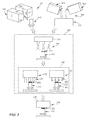
Fig. 3 is a diagrammatic illustration of a method for making a coated gas turbine engine component; -
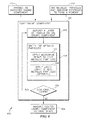
Fig. 4 is a block diagram of the method for making a coated gas turbine engine component as illustrated inFig. 3 ; and -
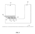
Fig. 5 is a cross-sectional view of a knife seal adapted for use in a gas turbine engine showing that the knife seal includes a coating applied to knife rings included in the knife seal. - For the purposes of promoting an understanding of the principles of the disclosure, reference will now be made to a number of illustrative embodiments illustrated in the drawings and specific language will be used to describe the same.
- A
blade 10 adapted for use in a gas turbine engine and having acoating 20 is shown inFig. 1 . Theblade 10 may include aroot 12, aplatform 14 coupled to theroot 12, and anairfoil 16 coupled to theplatform 14. Theblade 10 may also include thecoating 20 applied to adistal tip 18 of theairfoil 16 as depicted inFig. 1 . - The
coating 20 may protect thedistal tip 18 during use of theblade 10 in a gas turbine engine as suggested inFig. 1 . Thecoating 20 may illustratively include ametallic matrix 21 and a plurality ofabrasive particles 23. Themetallic matrix 21 may be joined to thedistal tip 18 of theairfoil 16 and may suspend theabrasive particles 23 in place relative to theairfoil 16. In illustrative embodiments, themetallic matrix 21 may be formed by applying microwaves to the metallic particles arranged along thedistal tip 18 of theairfoil 16 to sinter the metallic particles forming ametallic matrix 21 as suggested inFigs. 3 and4 . - The
root 12 of theblade 10 may be formed to includeattachment features 25 as shown inFig. 1 . In some embodiments, the attachment features of 25 may be fir-tree-type shoulders adapted to mate with corresponding features formed in a central wheel (not shown) to couple theblade 10 to the central wheel. Theplatform 14 may connect theroot 12 to theairfoil 16 and may separate theroot 12 from theairfoil 16 so that gasses passing over theairfoil 16 are blocked from moving down around theroot 12 as suggested inFig. 1 . - The
airfoil 16 may include aproximal end 17, thedistal tip 18, and abody 19 that extends between theproximal end 17 and thedistal tip 18 as shown inFig. 1 . Theproximal end 17 may be coupled to theplatform 14 and may be arranged to face theroot 12. Thedistal tip 18 may be opposite theproximal end 17 and may be arranged to face away from theroot 12. Thebody 19 may be shaped to aerodynamically interact with gasses passing over theairfoil 16. - The
metallic matrix 21 may act to hold theabrasive particles 23 in place to create an abrasive coating as depicted inFig. 2 . Themetallic matrix 21 may be comprised of any number of metallic particles including but not limited to nickel alloys, titanium alloys, cobalt alloys, refractory metal alloys, and/or chrome alloys. Theabrasive particle 23 to be held in place may include cubic boron nitride, aluminum oxide, zirconium, and/or titanium carbide. Another embodiment may include buoyant particles acting as theabrasive particles 23 wherein theabrasive particles 23 may be less dense than the surroundingmetallic matrix 21. Theabrasive particles 23 may also include hollow spherical powders where the outer shell may be denser or less dense then themetallic matrix 21. - One
illustrative method 110 for making a coated gasturbine engine component 111, such as theblade 10 ofFigs. 1 and 2 , is shown, inFigs. 3 and4 . In astep 112 of themethod 110, a gasturbine engine component 111 may be provided for coating. In anotherstep 114,metallic particles 113 andabrasive particles 115 may be mixed to create apowder 117 used to coat the gasturbine engine component 111 as suggested in the illustrative view ofFig. 3 and in the corresponding block diagram ofFig. 4 . - In illustrative embodiments, the
metallic particles 113 may include and/or be selected from nickel alloys, titanium allows, cobalt alloys, refractory metal alloys and chrome alloys. In other embodiments, themetallic particles 113 may include othermetallic materials 113. Themetallic particles 113 may be selected based on particulate size and ability to couple with themicrowaves 123 chosen. In illustrative embodiments, theabrasive particles 115 may include and/or be selected from cubic boron nitride, aluminum oxide, zirconium oxide, titanium carbide and silicon carbide. In other embodiments, theabrasive particles 115 may include other non-metallic or metallic materials. Theabrasive particles 115 and/or themicrowaves 123 may be selected such that themicrowaves 123 do not substantially couple to theabrasive particles 115. Thus, themicrowaves 123 may not directly heat theabrasive particles 115. The volume ratio of metallic particles to abrasive particles may be between about 100:1 and about 1:10. - The
method 110 may further include asub-process 116 of coating the gasturbine engine component 111 as shown inFigs. 3 and4 . The sub-process 116 may include astep 118 of applying thepowder 117 onto the gasturbine engine component 111 using anapplicator 119. Thestep 118 of applying thepowder 117 may be performed by various methods including, but not limited to painting the powder, preplacing powder compacts with binder, and blowing the powder. Step 118 may be followed bystep 120 of sintering or fusing themetallic particles 113 included in thepowder 117 to create a layer ofcoating 121 on the gasturbine engine component 111. - The
step 120 of sintering the metallic particles may include astep 122 of applyingmicrowaves 123 onto thepowder 117 to sinter or fuse themetallic particles 113 so that themetallic particles 113 form a metallic matrix. The wavelength range of themicrowaves 123 may be various values, including, but not limited to, between about 1 m and about 1 mm corresponding to a frequency range between about 300GHz and about 300MHz. The size range of themetallic particles 113 may also vary between about 2 micrometers and about 500 micrometers. In any event, the microwave wavelength and the size of themetallic particles 113 may be selected such that themicrowaves 123 couple with themetallic particles 113. Themicrowaves 123 may heat themetallic particles 113 to a temperature sufficient to sinter or fuse themetallic particles 113 but below the melting temperature of the metallic particles so that themetallic particles 113 do not melt. For example, themetallic particles 113 may be heated to a temperature between about 70% and about 99% of the melting temperature of the "metallic particles" 113. Usingmicrowaves 123 instep 122 may allow the layer ofpowder 114 to be heated in a uniform manner. - Microwave heating of particles has many advantages over traditional methods of heating material. One possible advantage is the cost savings by first preheating the
particulate using microwaves 123. Certain systems use a directedenergy beam 125 to raise the temperature of the material from room temperature to melting. By preheating the material withmicrowaves 123, the directedenergy beam 125 may not be used, or may only be used to raise the temperature of the material from a preheated temperature to the sintering temperature. - Another possible advantage may include more uniform distribution of heat provided by the
microwaves 123, which may result in more uniform and/or better material properties such as microstructure and mechanical properties. When particles are not preheated prior to sintering, the quick melting by the directed energy beam may leave residual stresses within the article resulting in cracking. - The sintered
metallic particles 113 may form a metallic matrix that may act to hold theabrasive particles 115 in place to create an abrasive coating like thecoating 20 shown inFigs. 1 and 2 . In some illustrative embodiments, thestep 120 of sintering themetallic particles 113 may also include anoptional step 124 of applying a directedenergy beam 125 to thepowder 117 to heat themetallic particles 113. Themicrowaves 123 may heat themetallic particles 113 to a temperature sufficient to sinter themetallic particles 113 but below the melting temperature of the metallic particles so that themetallic particles 113 do not melt. In one, non-limiting embodiment, the directed energy beam may be a laser beam. In yet another, non-limiting embodiment, the directed energy beam may be an electron beam. Thestep 124 of applying a directedenergy beam 125 to thepowder 117 may be performed concurrently with the application ofmicrowaves 123 in thestep 122 and/or after the application ofmicrowaves 123 in thestep 122. - The sub-process 116 may also include a
decision step 126 in which it is decided if an additional layer of coating is desired as shown diagrammatically inFig. 4 . If an additional layer of coating is desired, the sub-process 116 repeats step 118 applyingpowder 117 and step 120 sintering themetallic particles 113 in thepowder 117. If an additional layer of coating is not desired, the sub-process 116 may proceed to astep 128 of machining the coating and/or the gas turbine engine component 111 (illustratively using a grinder 129) to finalize the shape of the coated gasturbine engine component 111. - As shown in
Fig. 5 , a knife seal 210 may be an example application of a coating a gas turbine engine component. In a knife seal, theannular runner 212 may be made of an abradable material. During normal operation of the gas turbine engine, the knife rings 231, 232, and 234 may come in contact with the abradable material of theannular runner 212. The contact between the knife ring and theannular runner 212 works to form a seal, effectively sealing airflow from the gas turbine engine. A coating on theknife edge knife edge annular runner 212 creating a more wear resistant seal. A more wear resistant seal will allow the part to stay in use for longer durations without needing replacement. Another possible advantage may be the uniform distribution of heat provided by themicrowaves 123, which may result in more uniform and/or better material properties such as microstructure and mechanical properties. When particles are not preheated prior to sintering, the quick heating by the directed energy beam may leave residual stresses within the article resulting in cracking. Conserving the microstructure and mechanical properties of the material may also allow for less air flow creating a better seal. - The
annular runner 212 may be coupled to astatic structure 224 included in a gas turbine engine. The knife rings 231, 232, 233 may each have anattachment edge rotor 226 included in a gas turbine engine so that the knife rings 231, 232, 233 rotate with therotor 226 about anaxis 228 during operation of the gas turbine engine. In illustrative embodiments, the knife seal 210 may be produced using themethod 110 for making a coated gas turbine engine component as described herein and shown inFigs. 3 and4 . - A knife seal 210 adapted for use in a gas turbine engine and having a
coating 220 is shown inFig. 5 . The knife seal 210 may include anannular runner 212 and a plurality of knife rings 231, 232, 233. The plurality of knife seals 231, 232, 233 may be arranged to contact theannular runner 212 to form a seal between theannular runner 212 and the knife rings 231, 232, 233 during operation of the gas turbine engine. The knife seal 210 may also include thecoating 220 applied to aknife edge knife ring annular runner 212 and the knife rings 231, 232, 233. - The
coating 220 may be similar to thecoating 20 shown inFig. 2 and may protect the knife edges 241, 242, 243 of the knife rings 231, 232, 233 during operation of the gas turbine engine as suggested inFig. 5 . Thecoating 220 may include a metallic matrix and a plurality of abrasive particles. The metallic matrix may be joined to the knife edges 241, 242, 243 of the knife rings 231, 232, 233 and may suspend the abrasive particles in place relative to the knife rings 231, 232, 233. In illustrative embodiments, the metallic matrix may be formed by applyingmicrowaves 123 to metallic particles arranged along the knife edges 241, 242, 243 of the knife rings 231, 232, 233 to sinter the metallic particles into a matrix as suggested inFigs. 3 and4 . Themicrowaves 123 may heat the metallic particles so that themetallic particles 113 do not melt. For example, themetallic particles 113 may be heated to a temperature between about 70% and about 90% of the melting temperature of themetallic particles 113. In one, non-limiting embodiment, the directed energy beam may be a laser beam. In yet another, non-limiting embodiment, the directed energy beam may be an electron beam. - While the disclosure has been illustrated and described in detail in the foregoing drawings and description, the same is to be considered as exemplary and not restrictive in character, it being understood that only non-limitative illustrative embodiments thereof have been shown and described and that all changes and modifications that come within the scope of in the invention are desired to be protected.
Claims (15)
- A method of making a coated gas turbine engine component comprising:depositing a layer of powder including metallic particles and abrasive particles on a gas turbine engine component; andapplying microwaves to the layer of powder to heat the metallic particles in order to sinter the metallic particles into a metallic matrix joined to the gas turbine engine component.
- The method of claim 1, further comprising selecting a particle size of the metallic particles such that the microwaves couple to the metallic particles.
- The method of claim 1 or claim 2, further comprising selecting a wavelength of the microwaves such that the microwaves couple to the metallic particles.
- The method of any of the preceding claims, wherein a melt temperature of the abrasive particles is higher than a melt temperature of the metallic particles.
- The method of any of the preceding claims, further comprising applying a directed energy beam to the layer of powder to heat the metallic particles in order to fuse the metallic particles into the metallic matrix joined to the distal tip of the airfoil.
- The method of claim 5, wherein the applying the directed energy beam to the layer of powder is performed after the applying microwaves to the layer of powder or contemporaneously with at least a portion of the applying microwaves to the layer of powder.
- The method of any of the preceding claims, further comprising:selecting the metallic particles from a group consisting of nickel alloys, titanium alloys, cobalt alloys, refractory metal alloys and chrome alloys; and/orselecting the abrasive particles from a group consisting of: cubic boron nitride, aluminum oxide, zirconium oxide, titanium carbide and silicon carbide.
- A blade for use in a gas turbine engine, the blade comprising:a root formed to include an attachment feature adapted to mate with a central wheel to couple the blade to the central wheel,an airfoil having a proximal end arranged to face the root and a distal tip, opposite the proximal end, arranged to face away from the root, the airfoil and the root coupled together, anda coating applied to the distal tip of the airfoil to protect the distal tip during use of the blade.
- The blade of claim 8, wherein the coating is formed from a layer of powder including metallic particles and abrasive particles.
- The blade of claim 9, wherein:the metallic particles are from a group consisting of nickel alloys, titanium alloys, cobalt alloys, refractory metal alloys and chrome alloys; and/orthe abrasive particles from a group consisting of cubic boron nitride, aluminum oxide, zirconium oxide, titanium carbide and silicon carbide.
- The blade of any one of claims 8 to 10, wherein the coating is applied using the method of any one of claims 1 to 6.
- A knife seal for use in a gas turbine engine, the knife seal comprising:an annular runner adapted to be coupled to a static structure included in the gas turbine engine,an annular knife ring having an attachment edge adapted to be coupled to a rotor included in the gas turbine engine so that the annular knife ring rotates with the rotor and a knife ridge, opposite the attachment edge, that contacts the annular runner to form a seal there between, anda coating applied to the knife edge to protect the knife edge during use of the knife seal.
- The knife seal of claim 12, wherein the coating is formed from a layer of powder including metallic particles and abrasive particles.
- The blade of claim 13, wherein:the metallic particles are from a group consisting of nickel alloys, titanium alloys, cobalt alloys, refractory metal alloys and chrome alloys; and/orthe abrasive particles from a group consisting of cubic boron nitride, aluminum oxide, zirconium oxide, titanium carbide and silicon carbide.
- The knife seal of any of Claims 12-14, wherein the coating is applied using the method of any one of claims 1 to 6.
Applications Claiming Priority (1)
| Application Number | Priority Date | Filing Date | Title |
|---|---|---|---|
| US201462018914P | 2014-06-30 | 2014-06-30 |
Publications (3)
| Publication Number | Publication Date |
|---|---|
| EP2977560A2 true EP2977560A2 (en) | 2016-01-27 |
| EP2977560A3 EP2977560A3 (en) | 2016-05-25 |
| EP2977560B1 EP2977560B1 (en) | 2018-06-06 |
Family
ID=53496429
Family Applications (1)
| Application Number | Title | Priority Date | Filing Date |
|---|---|---|---|
| EP15172923.3A Revoked EP2977560B1 (en) | 2014-06-30 | 2015-06-19 | Method of making coated gas turbine engine components |
Country Status (3)
| Country | Link |
|---|---|
| US (2) | US10072506B2 (en) |
| EP (1) | EP2977560B1 (en) |
| CA (1) | CA2895627A1 (en) |
Cited By (1)
| Publication number | Priority date | Publication date | Assignee | Title |
|---|---|---|---|---|
| CN106112704A (en) * | 2016-08-26 | 2016-11-16 | 鞍山宏拓数控设备工程有限公司 | There is the cutter sharpener of laser coatings function |
Families Citing this family (7)
| Publication number | Priority date | Publication date | Assignee | Title |
|---|---|---|---|---|
| US10072506B2 (en) | 2014-06-30 | 2018-09-11 | Rolls-Royce Corporation | Coated gas turbine engine components |
| US10794221B2 (en) * | 2017-04-25 | 2020-10-06 | United Technologies Corporation | Gas turbine engine with geopolymer seal element |
| US10995623B2 (en) | 2018-04-23 | 2021-05-04 | Rolls-Royce Corporation | Ceramic matrix composite turbine blade with abrasive tip |
| US10954803B2 (en) | 2019-01-17 | 2021-03-23 | Rolls-Royce Corporation | Abrasive coating for high temperature mechanical systems |
| DE102019207350A1 (en) * | 2019-05-20 | 2020-11-26 | Siemens Aktiengesellschaft | Welding process with coated abrasive particles, coated abrasive particles, layer system and sealing system |
| CN112126883B (en) * | 2020-08-20 | 2021-11-19 | 西安交通大学 | Ultra-flat blade tip cutting coating with outward sharp corner and preparation method thereof |
| RU202076U1 (en) * | 2020-09-14 | 2021-01-28 | Юрий Павлович Кузнецов | TURBO ROTOR SEAL |
Family Cites Families (24)
| Publication number | Priority date | Publication date | Assignee | Title |
|---|---|---|---|---|
| US4548863A (en) * | 1984-11-29 | 1985-10-22 | Hicks Irwin A | Frangible seal coating and its method of production |
| US4802828A (en) * | 1986-12-29 | 1989-02-07 | United Technologies Corporation | Turbine blade having a fused metal-ceramic tip |
| US7563504B2 (en) * | 1998-03-27 | 2009-07-21 | Siemens Energy, Inc. | Utilization of discontinuous fibers for improving properties of high temperature insulation of ceramic matrix composites |
| DE69911948T2 (en) | 1999-08-09 | 2004-11-04 | Alstom Technology Ltd | Method for closing cooling openings of a gas turbine component |
| DE19951143A1 (en) | 1999-10-23 | 2001-04-26 | Christian Gerk | Process for heating ceramics, glass, metals and polymers or composites comprises combining laser and microwave heating in a suitable device |
| US6706319B2 (en) * | 2001-12-05 | 2004-03-16 | Siemens Westinghouse Power Corporation | Mixed powder deposition of components for wear, erosion and abrasion resistant applications |
| US6929852B2 (en) * | 2002-08-08 | 2005-08-16 | Siemens Westinghouse Power Corporation | Protective overlayer for ceramics |
| US7334330B2 (en) * | 2004-04-28 | 2008-02-26 | Siemens Power Generation, Inc. | Thermally insulating layer incorporating a distinguishing agent and method for inspecting the same |
| US7282681B2 (en) | 2005-05-05 | 2007-10-16 | General Electric Company | Microwave fabrication of airfoil tips |
| US20060251536A1 (en) | 2005-05-05 | 2006-11-09 | General Electric Company | Microwave processing of mim preforms |
| US20070107216A1 (en) * | 2005-10-31 | 2007-05-17 | General Electric Company | Mim method for coating turbine shroud |
| US7541561B2 (en) * | 2006-09-01 | 2009-06-02 | General Electric Company | Process of microwave heating of powder materials |
| US20080138533A1 (en) | 2006-12-12 | 2008-06-12 | General Electric Company | Microwave process for forming a coating |
| US8409318B2 (en) | 2006-12-15 | 2013-04-02 | General Electric Company | Process and apparatus for forming wire from powder materials |
| US8342386B2 (en) * | 2006-12-15 | 2013-01-01 | General Electric Company | Braze materials and processes therefor |
| GB0709838D0 (en) | 2007-05-23 | 2007-07-04 | Rolls Royce Plc | A hollow blade and a method of manufacturing a hollow blade |
| US8119247B2 (en) | 2008-12-19 | 2012-02-21 | General Electric Company | Environmental barrier coatings providing CMAS mitigation capability for ceramic substrate components |
| US8039113B2 (en) | 2008-12-19 | 2011-10-18 | General Electric Company | Environmental barrier coatings providing CMAS mitigation capability for ceramic substrate components |
| DE102009051552A1 (en) * | 2009-10-31 | 2011-05-05 | Mtu Aero Engines Gmbh | Method and device for producing a component |
| US8807955B2 (en) * | 2011-06-30 | 2014-08-19 | United Technologies Corporation | Abrasive airfoil tip |
| US9598973B2 (en) * | 2012-11-28 | 2017-03-21 | General Electric Company | Seal systems for use in turbomachines and methods of fabricating the same |
| US20150315090A1 (en) * | 2014-05-01 | 2015-11-05 | Siemens Energy, Inc. | Laser glazing using hollow objects for shrinkage compliance |
| US10072506B2 (en) | 2014-06-30 | 2018-09-11 | Rolls-Royce Corporation | Coated gas turbine engine components |
| US11268183B2 (en) * | 2015-05-06 | 2022-03-08 | Raytheon Technologies Corporation | Method of forming an abrasive coating on a fan blade tip |
-
2015
- 2015-06-09 US US14/734,834 patent/US10072506B2/en active Active
- 2015-06-19 EP EP15172923.3A patent/EP2977560B1/en not_active Revoked
- 2015-06-25 CA CA2895627A patent/CA2895627A1/en not_active Abandoned
-
2018
- 2018-07-31 US US16/050,934 patent/US10989057B2/en active Active
Non-Patent Citations (1)
| Title |
|---|
| None |
Cited By (2)
| Publication number | Priority date | Publication date | Assignee | Title |
|---|---|---|---|---|
| CN106112704A (en) * | 2016-08-26 | 2016-11-16 | 鞍山宏拓数控设备工程有限公司 | There is the cutter sharpener of laser coatings function |
| CN106112704B (en) * | 2016-08-26 | 2018-07-03 | 鞍山宏拓数控设备工程有限公司 | There is the cutter sharpener of laser coatings |
Also Published As
| Publication number | Publication date |
|---|---|
| EP2977560B1 (en) | 2018-06-06 |
| US20180355735A1 (en) | 2018-12-13 |
| EP2977560A3 (en) | 2016-05-25 |
| CA2895627A1 (en) | 2015-12-30 |
| US10989057B2 (en) | 2021-04-27 |
| US10072506B2 (en) | 2018-09-11 |
| US20150377039A1 (en) | 2015-12-31 |
Similar Documents
| Publication | Publication Date | Title |
|---|---|---|
| US10989057B2 (en) | Coated gas turbine engine components | |
| EP3018296B1 (en) | Gas turbine engine assembly with an abradable blade track and corresponding formation method | |
| EP3575555B1 (en) | Gas turbine engine blade and method of forming a gas turbine engine blade | |
| EP2067872B1 (en) | Article having composite layer | |
| CA1136669A (en) | Abradable ceramic seal and method of making same | |
| US4299865A (en) | Abradable ceramic seal and method of making same | |
| EP0796929B1 (en) | Abrasive Seal coatings | |
| US20160010469A1 (en) | Hybrid manufacturing for rotors | |
| EP1908856A2 (en) | Segmented abradable coatings and process(es) for applying the same | |
| JP2016204750A (en) | Article and method of forming the article | |
| JP2001164901A (en) | Turbine engine component with improved heat transfer and method of manufacturing the same | |
| EP2537619B1 (en) | Build-up welding method of fabricating a component and a manufactured component | |
| JP2013146728A (en) | Method for producing thermal barrier coating and article having cold sprayed thermal barrier coating | |
| US20190022753A1 (en) | Method for producing a component, and device | |
| CN105220103A (en) | Manufacture the method for guard shield abradable coating | |
| US10086459B2 (en) | Method for forming hybrid article | |
| JP2014163389A (en) | Cooled article | |
| CN106907187A (en) | Product and the method for forming product | |
| US20100055339A1 (en) | Method of forming molybdenum based wear resistant coating on a workpiece | |
| EP3332898B1 (en) | Heterogeneous composition, article comprising heterogeneous composition, and method for forming article | |
| US4371312A (en) | Bucket for an adjustable turbine inlet guide baffle system | |
| JP6855891B2 (en) | Thermal spraying powder and method for forming a thermal spray coating using this | |
| CN106964759A (en) | For the method and component using component of the set core formation with internal path | |
| CN110049839A (en) | Method for manufacturing gas turbine component | |
| US20170008135A1 (en) | Systems and methods for refurbishing a plunger of a gas well system |
Legal Events
| Date | Code | Title | Description |
|---|---|---|---|
| PUAI | Public reference made under article 153(3) epc to a published international application that has entered the european phase |
Free format text: ORIGINAL CODE: 0009012 |
|
| AK | Designated contracting states |
Kind code of ref document: A2 Designated state(s): AL AT BE BG CH CY CZ DE DK EE ES FI FR GB GR HR HU IE IS IT LI LT LU LV MC MK MT NL NO PL PT RO RS SE SI SK SM TR |
|
| AX | Request for extension of the european patent |
Extension state: BA ME |
|
| PUAL | Search report despatched |
Free format text: ORIGINAL CODE: 0009013 |
|
| AK | Designated contracting states |
Kind code of ref document: A3 Designated state(s): AL AT BE BG CH CY CZ DE DK EE ES FI FR GB GR HR HU IE IS IT LI LT LU LV MC MK MT NL NO PL PT RO RS SE SI SK SM TR |
|
| AX | Request for extension of the european patent |
Extension state: BA ME |
|
| RIC1 | Information provided on ipc code assigned before grant |
Ipc: F01D 11/12 20060101ALI20160421BHEP Ipc: F01D 11/02 20060101ALI20160421BHEP Ipc: C23C 24/10 20060101ALI20160421BHEP Ipc: B23K 35/22 20060101ALI20160421BHEP Ipc: F01D 11/00 20060101AFI20160421BHEP |
|
| STAA | Information on the status of an ep patent application or granted ep patent |
Free format text: STATUS: REQUEST FOR EXAMINATION WAS MADE |
|
| 17P | Request for examination filed |
Effective date: 20161118 |
|
| RBV | Designated contracting states (corrected) |
Designated state(s): AL AT BE BG CH CY CZ DE DK EE ES FI FR GB GR HR HU IE IS IT LI LT LU LV MC MK MT NL NO PL PT RO RS SE SI SK SM TR |
|
| REG | Reference to a national code |
Ref country code: DE Ref legal event code: R079 Ref document number: 602015011635 Country of ref document: DE Free format text: PREVIOUS MAIN CLASS: F01D0011000000 Ipc: C23C0024100000 |
|
| GRAP | Despatch of communication of intention to grant a patent |
Free format text: ORIGINAL CODE: EPIDOSNIGR1 |
|
| STAA | Information on the status of an ep patent application or granted ep patent |
Free format text: STATUS: GRANT OF PATENT IS INTENDED |
|
| RIC1 | Information provided on ipc code assigned before grant |
Ipc: F01D 5/28 20060101ALI20180119BHEP Ipc: C23C 24/08 20060101ALI20180119BHEP Ipc: F01D 5/20 20060101ALI20180119BHEP Ipc: C23C 24/10 20060101AFI20180119BHEP |
|
| INTG | Intention to grant announced |
Effective date: 20180221 |
|
| GRAS | Grant fee paid |
Free format text: ORIGINAL CODE: EPIDOSNIGR3 |
|
| GRAA | (expected) grant |
Free format text: ORIGINAL CODE: 0009210 |
|
| STAA | Information on the status of an ep patent application or granted ep patent |
Free format text: STATUS: THE PATENT HAS BEEN GRANTED |
|
| AK | Designated contracting states |
Kind code of ref document: B1 Designated state(s): AL AT BE BG CH CY CZ DE DK EE ES FI FR GB GR HR HU IE IS IT LI LT LU LV MC MK MT NL NO PL PT RO RS SE SI SK SM TR |
|
| REG | Reference to a national code |
Ref country code: GB Ref legal event code: FG4D |
|
| REG | Reference to a national code |
Ref country code: CH Ref legal event code: EP Ref country code: AT Ref legal event code: REF Ref document number: 1006173 Country of ref document: AT Kind code of ref document: T Effective date: 20180615 |
|
| REG | Reference to a national code |
Ref country code: FR Ref legal event code: PLFP Year of fee payment: 4 |
|
| REG | Reference to a national code |
Ref country code: IE Ref legal event code: FG4D |
|
| REG | Reference to a national code |
Ref country code: DE Ref legal event code: R096 Ref document number: 602015011635 Country of ref document: DE |
|
| REG | Reference to a national code |
Ref country code: NL Ref legal event code: MP Effective date: 20180606 |
|
| REG | Reference to a national code |
Ref country code: LT Ref legal event code: MG4D |
|
| PG25 | Lapsed in a contracting state [announced via postgrant information from national office to epo] |
Ref country code: NO Free format text: LAPSE BECAUSE OF FAILURE TO SUBMIT A TRANSLATION OF THE DESCRIPTION OR TO PAY THE FEE WITHIN THE PRESCRIBED TIME-LIMIT Effective date: 20180906 Ref country code: BG Free format text: LAPSE BECAUSE OF FAILURE TO SUBMIT A TRANSLATION OF THE DESCRIPTION OR TO PAY THE FEE WITHIN THE PRESCRIBED TIME-LIMIT Effective date: 20180906 Ref country code: FI Free format text: LAPSE BECAUSE OF FAILURE TO SUBMIT A TRANSLATION OF THE DESCRIPTION OR TO PAY THE FEE WITHIN THE PRESCRIBED TIME-LIMIT Effective date: 20180606 Ref country code: LT Free format text: LAPSE BECAUSE OF FAILURE TO SUBMIT A TRANSLATION OF THE DESCRIPTION OR TO PAY THE FEE WITHIN THE PRESCRIBED TIME-LIMIT Effective date: 20180606 Ref country code: ES Free format text: LAPSE BECAUSE OF FAILURE TO SUBMIT A TRANSLATION OF THE DESCRIPTION OR TO PAY THE FEE WITHIN THE PRESCRIBED TIME-LIMIT Effective date: 20180606 Ref country code: SE Free format text: LAPSE BECAUSE OF FAILURE TO SUBMIT A TRANSLATION OF THE DESCRIPTION OR TO PAY THE FEE WITHIN THE PRESCRIBED TIME-LIMIT Effective date: 20180606 Ref country code: CY Free format text: LAPSE BECAUSE OF FAILURE TO SUBMIT A TRANSLATION OF THE DESCRIPTION OR TO PAY THE FEE WITHIN THE PRESCRIBED TIME-LIMIT Effective date: 20180606 |
|
| PG25 | Lapsed in a contracting state [announced via postgrant information from national office to epo] |
Ref country code: LV Free format text: LAPSE BECAUSE OF FAILURE TO SUBMIT A TRANSLATION OF THE DESCRIPTION OR TO PAY THE FEE WITHIN THE PRESCRIBED TIME-LIMIT Effective date: 20180606 Ref country code: RS Free format text: LAPSE BECAUSE OF FAILURE TO SUBMIT A TRANSLATION OF THE DESCRIPTION OR TO PAY THE FEE WITHIN THE PRESCRIBED TIME-LIMIT Effective date: 20180606 Ref country code: HR Free format text: LAPSE BECAUSE OF FAILURE TO SUBMIT A TRANSLATION OF THE DESCRIPTION OR TO PAY THE FEE WITHIN THE PRESCRIBED TIME-LIMIT Effective date: 20180606 Ref country code: GR Free format text: LAPSE BECAUSE OF FAILURE TO SUBMIT A TRANSLATION OF THE DESCRIPTION OR TO PAY THE FEE WITHIN THE PRESCRIBED TIME-LIMIT Effective date: 20180907 |
|
| REG | Reference to a national code |
Ref country code: AT Ref legal event code: MK05 Ref document number: 1006173 Country of ref document: AT Kind code of ref document: T Effective date: 20180606 |
|
| PG25 | Lapsed in a contracting state [announced via postgrant information from national office to epo] |
Ref country code: NL Free format text: LAPSE BECAUSE OF FAILURE TO SUBMIT A TRANSLATION OF THE DESCRIPTION OR TO PAY THE FEE WITHIN THE PRESCRIBED TIME-LIMIT Effective date: 20180606 |
|
| PG25 | Lapsed in a contracting state [announced via postgrant information from national office to epo] |
Ref country code: EE Free format text: LAPSE BECAUSE OF FAILURE TO SUBMIT A TRANSLATION OF THE DESCRIPTION OR TO PAY THE FEE WITHIN THE PRESCRIBED TIME-LIMIT Effective date: 20180606 Ref country code: PL Free format text: LAPSE BECAUSE OF FAILURE TO SUBMIT A TRANSLATION OF THE DESCRIPTION OR TO PAY THE FEE WITHIN THE PRESCRIBED TIME-LIMIT Effective date: 20180606 Ref country code: IS Free format text: LAPSE BECAUSE OF FAILURE TO SUBMIT A TRANSLATION OF THE DESCRIPTION OR TO PAY THE FEE WITHIN THE PRESCRIBED TIME-LIMIT Effective date: 20181006 Ref country code: AT Free format text: LAPSE BECAUSE OF FAILURE TO SUBMIT A TRANSLATION OF THE DESCRIPTION OR TO PAY THE FEE WITHIN THE PRESCRIBED TIME-LIMIT Effective date: 20180606 Ref country code: SK Free format text: LAPSE BECAUSE OF FAILURE TO SUBMIT A TRANSLATION OF THE DESCRIPTION OR TO PAY THE FEE WITHIN THE PRESCRIBED TIME-LIMIT Effective date: 20180606 Ref country code: CZ Free format text: LAPSE BECAUSE OF FAILURE TO SUBMIT A TRANSLATION OF THE DESCRIPTION OR TO PAY THE FEE WITHIN THE PRESCRIBED TIME-LIMIT Effective date: 20180606 Ref country code: RO Free format text: LAPSE BECAUSE OF FAILURE TO SUBMIT A TRANSLATION OF THE DESCRIPTION OR TO PAY THE FEE WITHIN THE PRESCRIBED TIME-LIMIT Effective date: 20180606 |
|
| REG | Reference to a national code |
Ref country code: CH Ref legal event code: PL |
|
| REG | Reference to a national code |
Ref country code: DE Ref legal event code: R026 Ref document number: 602015011635 Country of ref document: DE |
|
| PLBI | Opposition filed |
Free format text: ORIGINAL CODE: 0009260 |
|
| PG25 | Lapsed in a contracting state [announced via postgrant information from national office to epo] |
Ref country code: SM Free format text: LAPSE BECAUSE OF FAILURE TO SUBMIT A TRANSLATION OF THE DESCRIPTION OR TO PAY THE FEE WITHIN THE PRESCRIBED TIME-LIMIT Effective date: 20180606 Ref country code: IT Free format text: LAPSE BECAUSE OF FAILURE TO SUBMIT A TRANSLATION OF THE DESCRIPTION OR TO PAY THE FEE WITHIN THE PRESCRIBED TIME-LIMIT Effective date: 20180606 |
|
| REG | Reference to a national code |
Ref country code: BE Ref legal event code: MM Effective date: 20180630 |
|
| 26 | Opposition filed |
Opponent name: UNITED TECHNOLOGIES CORPORATION Effective date: 20190208 |
|
| PLAX | Notice of opposition and request to file observation + time limit sent |
Free format text: ORIGINAL CODE: EPIDOSNOBS2 |
|
| REG | Reference to a national code |
Ref country code: IE Ref legal event code: MM4A |
|
| PG25 | Lapsed in a contracting state [announced via postgrant information from national office to epo] |
Ref country code: MC Free format text: LAPSE BECAUSE OF FAILURE TO SUBMIT A TRANSLATION OF THE DESCRIPTION OR TO PAY THE FEE WITHIN THE PRESCRIBED TIME-LIMIT Effective date: 20180606 Ref country code: LU Free format text: LAPSE BECAUSE OF NON-PAYMENT OF DUE FEES Effective date: 20180619 |
|
| PG25 | Lapsed in a contracting state [announced via postgrant information from national office to epo] |
Ref country code: IE Free format text: LAPSE BECAUSE OF NON-PAYMENT OF DUE FEES Effective date: 20180619 Ref country code: LI Free format text: LAPSE BECAUSE OF NON-PAYMENT OF DUE FEES Effective date: 20180630 Ref country code: CH Free format text: LAPSE BECAUSE OF NON-PAYMENT OF DUE FEES Effective date: 20180630 |
|
| PG25 | Lapsed in a contracting state [announced via postgrant information from national office to epo] |
Ref country code: DK Free format text: LAPSE BECAUSE OF FAILURE TO SUBMIT A TRANSLATION OF THE DESCRIPTION OR TO PAY THE FEE WITHIN THE PRESCRIBED TIME-LIMIT Effective date: 20180606 Ref country code: BE Free format text: LAPSE BECAUSE OF NON-PAYMENT OF DUE FEES Effective date: 20180630 Ref country code: SI Free format text: LAPSE BECAUSE OF FAILURE TO SUBMIT A TRANSLATION OF THE DESCRIPTION OR TO PAY THE FEE WITHIN THE PRESCRIBED TIME-LIMIT Effective date: 20180606 |
|
| PLBB | Reply of patent proprietor to notice(s) of opposition received |
Free format text: ORIGINAL CODE: EPIDOSNOBS3 |
|
| PG25 | Lapsed in a contracting state [announced via postgrant information from national office to epo] |
Ref country code: AL Free format text: LAPSE BECAUSE OF FAILURE TO SUBMIT A TRANSLATION OF THE DESCRIPTION OR TO PAY THE FEE WITHIN THE PRESCRIBED TIME-LIMIT Effective date: 20180606 |
|
| PG25 | Lapsed in a contracting state [announced via postgrant information from national office to epo] |
Ref country code: MT Free format text: LAPSE BECAUSE OF NON-PAYMENT OF DUE FEES Effective date: 20180619 |
|
| GBPC | Gb: european patent ceased through non-payment of renewal fee |
Effective date: 20190619 |
|
| PG25 | Lapsed in a contracting state [announced via postgrant information from national office to epo] |
Ref country code: TR Free format text: LAPSE BECAUSE OF FAILURE TO SUBMIT A TRANSLATION OF THE DESCRIPTION OR TO PAY THE FEE WITHIN THE PRESCRIBED TIME-LIMIT Effective date: 20180606 |
|
| PG25 | Lapsed in a contracting state [announced via postgrant information from national office to epo] |
Ref country code: GB Free format text: LAPSE BECAUSE OF NON-PAYMENT OF DUE FEES Effective date: 20190619 |
|
| PG25 | Lapsed in a contracting state [announced via postgrant information from national office to epo] |
Ref country code: PT Free format text: LAPSE BECAUSE OF FAILURE TO SUBMIT A TRANSLATION OF THE DESCRIPTION OR TO PAY THE FEE WITHIN THE PRESCRIBED TIME-LIMIT Effective date: 20180606 |
|
| PG25 | Lapsed in a contracting state [announced via postgrant information from national office to epo] |
Ref country code: MK Free format text: LAPSE BECAUSE OF NON-PAYMENT OF DUE FEES Effective date: 20180606 Ref country code: HU Free format text: LAPSE BECAUSE OF FAILURE TO SUBMIT A TRANSLATION OF THE DESCRIPTION OR TO PAY THE FEE WITHIN THE PRESCRIBED TIME-LIMIT; INVALID AB INITIO Effective date: 20150619 |
|
| PGFP | Annual fee paid to national office [announced via postgrant information from national office to epo] |
Ref country code: FR Payment date: 20200626 Year of fee payment: 6 |
|
| PLAB | Opposition data, opponent's data or that of the opponent's representative modified |
Free format text: ORIGINAL CODE: 0009299OPPO |
|
| R26 | Opposition filed (corrected) |
Opponent name: RAYTHEON TECHNOLOGIES CORPORATION Effective date: 20190208 |
|
| PGFP | Annual fee paid to national office [announced via postgrant information from national office to epo] |
Ref country code: DE Payment date: 20200827 Year of fee payment: 6 |
|
| REG | Reference to a national code |
Ref country code: DE Ref legal event code: R064 Ref document number: 602015011635 Country of ref document: DE Ref country code: DE Ref legal event code: R103 Ref document number: 602015011635 Country of ref document: DE |
|
| RDAF | Communication despatched that patent is revoked |
Free format text: ORIGINAL CODE: EPIDOSNREV1 |
|
| RDAG | Patent revoked |
Free format text: ORIGINAL CODE: 0009271 |
|
| STAA | Information on the status of an ep patent application or granted ep patent |
Free format text: STATUS: PATENT REVOKED |
|
| REG | Reference to a national code |
Ref country code: FI Ref legal event code: MGE |
|
| 27W | Patent revoked |
Effective date: 20210115 |