EP2977545A1 - Method and device for cleaning control particles in a wellbore - Google Patents
Method and device for cleaning control particles in a wellbore Download PDFInfo
- Publication number
- EP2977545A1 EP2977545A1 EP14178419.9A EP14178419A EP2977545A1 EP 2977545 A1 EP2977545 A1 EP 2977545A1 EP 14178419 A EP14178419 A EP 14178419A EP 2977545 A1 EP2977545 A1 EP 2977545A1
- Authority
- EP
- European Patent Office
- Prior art keywords
- shock wave
- control
- control particles
- borehole
- particles
- Prior art date
- Legal status (The legal status is an assumption and is not a legal conclusion. Google has not performed a legal analysis and makes no representation as to the accuracy of the status listed.)
- Granted
Links
- 239000002245 particle Substances 0.000 title claims abstract description 121
- 238000000034 method Methods 0.000 title claims abstract description 39
- 238000004140 cleaning Methods 0.000 title claims abstract description 26
- 230000035939 shock Effects 0.000 claims abstract description 94
- 230000015572 biosynthetic process Effects 0.000 claims abstract description 83
- 239000012530 fluid Substances 0.000 claims abstract description 37
- 239000012528 membrane Substances 0.000 claims abstract description 29
- 239000007789 gas Substances 0.000 claims abstract description 26
- 238000011084 recovery Methods 0.000 claims abstract description 10
- 230000001902 propagating effect Effects 0.000 claims abstract description 3
- 239000007788 liquid Substances 0.000 claims description 29
- 229910052500 inorganic mineral Inorganic materials 0.000 claims description 9
- 239000011707 mineral Substances 0.000 claims description 9
- 239000000919 ceramic Substances 0.000 claims description 8
- 238000003860 storage Methods 0.000 claims description 7
- 230000000644 propagated effect Effects 0.000 claims description 6
- 238000006243 chemical reaction Methods 0.000 claims description 4
- 229920001971 elastomer Polymers 0.000 claims description 3
- 229920001973 fluoroelastomer Polymers 0.000 claims description 3
- 238000005755 formation reaction Methods 0.000 description 71
- 239000004576 sand Substances 0.000 description 27
- 238000004519 manufacturing process Methods 0.000 description 17
- 239000000126 substance Substances 0.000 description 12
- 230000000903 blocking effect Effects 0.000 description 11
- 239000002253 acid Substances 0.000 description 8
- 239000003921 oil Substances 0.000 description 6
- 239000011159 matrix material Substances 0.000 description 5
- VTYYLEPIZMXCLO-UHFFFAOYSA-L Calcium carbonate Chemical compound [Ca+2].[O-]C([O-])=O VTYYLEPIZMXCLO-UHFFFAOYSA-L 0.000 description 4
- 229910001570 bauxite Inorganic materials 0.000 description 4
- 239000000203 mixture Substances 0.000 description 4
- 230000008569 process Effects 0.000 description 4
- TZCXTZWJZNENPQ-UHFFFAOYSA-L barium sulfate Chemical compound [Ba+2].[O-]S([O-])(=O)=O TZCXTZWJZNENPQ-UHFFFAOYSA-L 0.000 description 3
- 230000004888 barrier function Effects 0.000 description 3
- 239000003990 capacitor Substances 0.000 description 3
- -1 for example gravels Substances 0.000 description 3
- 238000002347 injection Methods 0.000 description 3
- 239000007924 injection Substances 0.000 description 3
- 239000000463 material Substances 0.000 description 3
- 238000012856 packing Methods 0.000 description 3
- 239000002244 precipitate Substances 0.000 description 3
- 239000000243 solution Substances 0.000 description 3
- 238000011282 treatment Methods 0.000 description 3
- XLYOFNOQVPJJNP-UHFFFAOYSA-N water Substances O XLYOFNOQVPJJNP-UHFFFAOYSA-N 0.000 description 3
- OYPRJOBELJOOCE-UHFFFAOYSA-N Calcium Chemical compound [Ca] OYPRJOBELJOOCE-UHFFFAOYSA-N 0.000 description 2
- 150000001338 aliphatic hydrocarbons Chemical class 0.000 description 2
- 150000004945 aromatic hydrocarbons Chemical class 0.000 description 2
- 229910052791 calcium Inorganic materials 0.000 description 2
- 239000011575 calcium Substances 0.000 description 2
- 229910000019 calcium carbonate Inorganic materials 0.000 description 2
- OSGAYBCDTDRGGQ-UHFFFAOYSA-L calcium sulfate Chemical compound [Ca+2].[O-]S([O-])(=O)=O OSGAYBCDTDRGGQ-UHFFFAOYSA-L 0.000 description 2
- 239000013043 chemical agent Substances 0.000 description 2
- 230000008878 coupling Effects 0.000 description 2
- 238000010168 coupling process Methods 0.000 description 2
- 238000005859 coupling reaction Methods 0.000 description 2
- 230000006735 deficit Effects 0.000 description 2
- 239000000446 fuel Substances 0.000 description 2
- 239000008187 granular material Substances 0.000 description 2
- 230000005484 gravity Effects 0.000 description 2
- 229930195733 hydrocarbon Natural products 0.000 description 2
- 230000037361 pathway Effects 0.000 description 2
- 239000007787 solid Substances 0.000 description 2
- 239000004215 Carbon black (E152) Substances 0.000 description 1
- YCKRFDGAMUMZLT-UHFFFAOYSA-N Fluorine atom Chemical compound [F] YCKRFDGAMUMZLT-UHFFFAOYSA-N 0.000 description 1
- 241000282887 Suidae Species 0.000 description 1
- NINIDFKCEFEMDL-UHFFFAOYSA-N Sulfur Chemical compound [S] NINIDFKCEFEMDL-UHFFFAOYSA-N 0.000 description 1
- 229910052788 barium Inorganic materials 0.000 description 1
- DSAJWYNOEDNPEQ-UHFFFAOYSA-N barium atom Chemical compound [Ba] DSAJWYNOEDNPEQ-UHFFFAOYSA-N 0.000 description 1
- 239000006227 byproduct Substances 0.000 description 1
- 229910010293 ceramic material Inorganic materials 0.000 description 1
- 239000003795 chemical substances by application Substances 0.000 description 1
- 239000004927 clay Substances 0.000 description 1
- 239000003245 coal Substances 0.000 description 1
- 230000000295 complement effect Effects 0.000 description 1
- 230000006835 compression Effects 0.000 description 1
- 238000007906 compression Methods 0.000 description 1
- 230000007423 decrease Effects 0.000 description 1
- 230000000593 degrading effect Effects 0.000 description 1
- 230000001419 dependent effect Effects 0.000 description 1
- 238000005553 drilling Methods 0.000 description 1
- 230000000694 effects Effects 0.000 description 1
- 230000007613 environmental effect Effects 0.000 description 1
- 230000007717 exclusion Effects 0.000 description 1
- 238000002474 experimental method Methods 0.000 description 1
- 239000011737 fluorine Substances 0.000 description 1
- 229910052731 fluorine Inorganic materials 0.000 description 1
- 150000002430 hydrocarbons Chemical class 0.000 description 1
- 238000011065 in-situ storage Methods 0.000 description 1
- 239000012212 insulator Substances 0.000 description 1
- 230000003993 interaction Effects 0.000 description 1
- 229910052751 metal Inorganic materials 0.000 description 1
- 239000002184 metal Substances 0.000 description 1
- 150000002739 metals Chemical class 0.000 description 1
- 239000012188 paraffin wax Substances 0.000 description 1
- 230000000737 periodic effect Effects 0.000 description 1
- 239000003208 petroleum Substances 0.000 description 1
- 239000011148 porous material Substances 0.000 description 1
- 238000001556 precipitation Methods 0.000 description 1
- 238000005086 pumping Methods 0.000 description 1
- 239000011347 resin Substances 0.000 description 1
- 229920005989 resin Polymers 0.000 description 1
- 230000004044 response Effects 0.000 description 1
- 150000003839 salts Chemical class 0.000 description 1
- 239000011343 solid material Substances 0.000 description 1
- 230000000087 stabilizing effect Effects 0.000 description 1
- 239000004575 stone Substances 0.000 description 1
- 229910052717 sulfur Inorganic materials 0.000 description 1
- 239000011593 sulfur Substances 0.000 description 1
- 230000000153 supplemental effect Effects 0.000 description 1
Images


Classifications
-
- E—FIXED CONSTRUCTIONS
- E21—EARTH DRILLING; MINING
- E21B—EARTH DRILLING, e.g. DEEP DRILLING; OBTAINING OIL, GAS, WATER, SOLUBLE OR MELTABLE MATERIALS OR A SLURRY OF MINERALS FROM WELLS
- E21B37/00—Methods or apparatus for cleaning boreholes or wells
- E21B37/08—Methods or apparatus for cleaning boreholes or wells cleaning in situ of down-hole filters, screens, e.g. casing perforations, or gravel packs
-
- B—PERFORMING OPERATIONS; TRANSPORTING
- B08—CLEANING
- B08B—CLEANING IN GENERAL; PREVENTION OF FOULING IN GENERAL
- B08B7/00—Cleaning by methods not provided for in a single other subclass or a single group in this subclass
- B08B7/02—Cleaning by methods not provided for in a single other subclass or a single group in this subclass by distortion, beating, or vibration of the surface to be cleaned
Abstract
Description
- The field of the invention relates to the cleaning of a wellbore and associated equipment and, more particularly, to a method and device for cleaning control particles arranged in a wellbore in order to improve the recovery of formation fluids and/or gases.
- A preferred application of the invention concerns removing mineral deposits and reservoir fines from control particles arranged in a wellbore of a subterranean formation and/or redistributing mineral deposits and reservoir fines between control particles arranged in a wellbore of a subterranean formation.
- In the art of well boring, a borehole is drilled into the earth through the oil or gas producing subterranean formation or, for some purposes, through a water bearing formation or a formation into which water or gas or other liquids that are to be injected.
- Completion of a well may be carried out in a number of ways dependent upon the nature of the formation of interest. Where the formation itself or formations above the formation of interest have a tendency to disintegrate and/or cave into the hole, like e.g. sand formations, it is known to use a filter apparatus to control unconsolidated formation elements while allowing the passage of oil or gas from the formation in conjunction with particles or solids.
- For example, in sand formations, one common type of filter apparatus, called gravel pack, involves placing a control screen in the wellbore and packing the annulus between the screen and the wellbore wall with control particles of a specific size designed to prevent the passage of formation sand. Such control particles are made of a granular material such as for example gravels, ceramics or sintered bauxite. The main objective is to stabilize the formation while causing minimal impairment to well productivity, which means that it is critical to completely pack the space between the screen and the formation, preventing the movement of formation particles.
- In addition to the use of control screens or similar apparatus, gravel packing operations may involve the use of a wide variety of control equipment, including liners (e.g., slotted liners, perforated liners, etc.), combinations of liners and screens, and other suitable apparatus. A wide range of sizes and screen configurations are available to suit the characteristics of the control particles used. Similarly, a wide range of sizes of control particles are available to suit the characteristics of the unconsolidated formation elements. The resulting structure presents a barrier to migrating sand from the formation while still permitting fluid or gas flow.
- Another type of filter apparatus involves placing a control screen in the wellbore and packing the annulus between said control screen and the wellbore wall with control particles of a specific size designed to keep formation fissures open. In this case, the control particles, called proppant agents, may be for example sand or stone, ceramics or sintered bauxite.
- In any event, after a period of production, injection or transportation of fluids or gases, there is a tendency for the interstitial space between control particles to become plugged with various types of residues. For example, organic residues like paraffin, asphalts and other agglomerating residues of petroleum origin often cause plugging problems. Usually these deposits may cause significant problems, because of their composition and the fact that they may precipitate under certain conditions (pressure, temperature, liquid composition, injection...).
- These materials of mineral or organic origins either together with chemicals from water, normally produced with the oil, such as, calcium carbonate, calcium sulfate, barium sulfate, sulfur and the like, or such chemicals themselves have a tendency to form extremely hard deposits on different parts of the components. Such deposits may adhere to the control particles, blocking the interstitial spaces between said control particles, therefore reducing or completely preventing the flow of fluids or gases through the control particles to the borehole. Similar problems may also be encountered due to precipitates build on the control screen, due to pressure drop and temperature considerations and the gravel pack like e.g. solid salts (for example calcium or barium sulfates, calcium carbonate, calcium/barium scales, etc...).
- Another challenge encountered while using a control apparatus is migrating fines that plug the control particles and the control screen, impeding fluid flow and causing production levels to drop. As used in this disclosure, the term "fines" refers to loose elements, such as formation fines, formation sand, clay particles, coal fines, resin particles, crushed control particles, and the like. These migrating fines may also obstruct fluid pathways through the control apparatus lining the well. In particular, in situ fines mobilized during production, or injection, may lodge themselves in control screens, preventing or reducing fluid flow there through. Migrating fines may also be associated with either organic and or mineral precipitation byproducts downhole.
- Well-stimulation techniques using chemical agents, such as matrix acidizing, have been developed to remediate wells affected by these problems. An existing solution using chemical agents for cleaning gravel packs is described e.g. in patent
US7896080B1 . In matrix acidizing, thousands of gallons of acid are injected into the well to dissolve away precipitates, fines, or scale deposits on the inside of tubular parts, trapped in the openings of the control screen, or in the pore spaces of gravel pack or matrix formation. However, acidizing may not in all cases allow in most cases dissolving significant amounts of the plugging materials as acid does not penetrate more than a few inches behind the control screen. Moreover, chemicals may damage the control particles, which can break into pieces or in the case of clays swell them, therefore reducing or completely preventing the flow of fluids or gases through the control particles and the control screen. Furthermore, existing chemicals treatments may not be efficient in horizontal boreholes due to the volumes required or the paths the chemicals take. Additionally, the acid must is usually removed from the well. Often, depending on well fluids and reservoir composition, the well must also be flushed with pre- and post-acid solutions. Aside from the difficulties of determining the proper chemical composition for these fluids and pumping them down the well, the environmental costs of matrix acidizing can render the process undesirable. Additionally, matrix acidizing treatments generally only provide a temporary solution to these problems and do not take into consideration root cause. - Alternative mechanical techniques may also be used to clean gravel packs. For example, a cleanup liquid may be introduced into control particles utilizing pressure pulses or jets as described in patent application
US2005061503A1 or in patent applicationUS2007187090A1 . Typically, these techniques do not facilitate removal of significant amounts of the plugging materials as the cleanup liquid does not penetrate more than a few inches behind or into the control screen. There are also instances where, the cleanup liquid may damage the control particles, which can break into pieces, therefore reducing or completely preventing the flow of fluids or gases through the control particles to the screen. Furthermore, such techniques are not efficient in horizontal borehole as the cleanup liquid falls down with gravity. - It is therefore an object of the present invention to provide an improved method and device for efficiently, rapidly, easily and effectively cleaning control particles arranged in a borehole extending into the earth without damaging said control particles or degrading the nearby environment. Another and further object of the present invention is to provide an improved method and device for removing deposits encrusted on control particles, in particular in areas where the control particles are accessible with difficulty or inaccessible. Yet another object of the present invention is to provide an improved method and device for increasing the production of fluids or gases from a subsurface earth formation or increasing the injectivity of fluids or gases into such formations.
- To this end, the present invention concerns a method for cleaning control particles in a wellbore of a subterranean formation to improve the recovery of formation fluids and/or gases, said wellbore comprising a wall defining a borehole, at least one control equipment arranged into said borehole and a plurality of control particles arranged between said control equipment and said wall, said method comprising the steps of generating at least one shock wave nearby said control equipment and propagating said at least one shock wave through said control equipment toward said control particles for cleaning said control particles.
- The control particles of a specific size are designed to prevent the passage of elements such as sand and/or fines and constitute a barrier to migrating elements while still permitting fluid flow from the formation. In other words, the control equipment acts as a filter which allows the passage of formation fluids and/or gases while retaining the control particles against the wall of the borehole and preventing elements such as e.g. sand from passing through.
- The method according to the invention allows thus efficiently, easily and rapidly cleaning the control particles arranged between the control equipment and the wellbore wall while not damaging the formation (unlike e.g. acid). Advantageously, the propagated at least one shock wave may reach control particles which are accessible with difficulty or inaccessible to chemical and/or mechanical means. In particular, the propagated at least one shock wave may reach control particles which are arranged in perforations extending into the formation for collecting formation fluids. Moreover, the method according to the invention is particularly efficient for removing deposits, in particular mineral deposits, from said control particles. The method according to the invention In fact the shock wave invention would complement the use chemical or mechanical means by creating pathways through said control particles and control equipment.
- In one embodiment of the method according to the invention, the control particles are ceramic control particles. The control particles may also be other types of granular material such as gravel, sand, sintered bauxite, proppant particles, metals, any other suitable control particles allowing preventing the passage of formation sand while still permitting fluid flow from the formation. The method according to the invention is particularly efficient for removing mineral deposits from ceramic control particles.
- Moreover, the method according to the invention allows advantageously cleaning control particles and the control equipment simultaneously. The control equipment may be a screen, a liner (e.g. a slotted liner, a perforated liner, a mesh screen etc.), a combination of a liner and a screen or any other suitable apparatus. In a preferred embodiment, the control equipment is a control screen.
- Advantageously, the control screen is a pipe, the control particles being packed or wound into the annulus defined between said pipe and the wellbore wall.
- In particular, the at least one propagated shock wave may reach areas where the control particles are located and which accessible with difficulty or inaccessible to mechanical means such as e.g. brushes, scrapers or pigs or to chemical means such as e.g. acid.
- In an embodiment according to the invention, a series of at least ten shock waves is generated for efficiently removing deposits from the control particles.
- In a preferred embodiment, a plurality of series of shock waves is generated, each series of shock waves being generated repeatedly at different locations near the control equipment, for example different heights of a control screen. Preferably, the different locations are regularly spaced.
- Using a plurality of series of shock waves allows advantageously removing most of the deposits from control particles, between 80-95% and preferably more than 95% of the deposits.
- Preferably, the at least one shock wave propagates radially.
- In another embodiment, the at least one shock wave propagates in a predetermined direction.
- In a preferred embodiment, the at least one shock wave is generated in a transmitting liquid which is at least partially delimited by a membrane and the at least one shock wave is propagated through said membrane toward the control particles for cleaning said control particles. Such a membrane improves the effectiveness of the propagation from the liquid to the control particles.
- The invention also concerns a shock wave generation device for cleaning control particles in a wellbore of a subterranean formation to improve the recovery of formation fluids and/or gases, said wellbore comprising a wall defining a borehole, at least one control equipment arranged into said borehole and a plurality of control particles arranged between said control equipment and said wall, said device comprising:
- a chamber which is partially filled with a shock wave transmitting liquid and which is adapted to be arranged into said borehole nearby said control equipment; and
- an electrical discharge unit for generating at least one electrical discharge that propagates at least one shock wave into said shock wave transmitting liquid through said control equipment and said control particles for cleaning said control particles.
- In a preferred embodiment, the chamber is at least partially delimited by a membrane and the electrical discharge unit is configured for generating at least one electrical discharge that propagates at least one shock wave into said shock wave transmitting liquid through said membrane nearby said control equipment for cleaning said control particles.
- The membrane improves the effectiveness of the propagation from the liquid to the control equipment and the control particles. Moreover, such a membrane isolates the liquid in the chamber from elements of the wellbore surrounding the shock wave generating device, such as e.g. mud or other fluids, while maintaining acoustic coupling with the control equipment. Such a flexible membrane prevents in particular the deposits and other elements from damaging electrodes and other components (insulators) of the electrical discharge unit.
- Preferably, the membrane is deformable and/or flexible and/or elastic in order to conduct efficiently the shock wave toward the control particles.
- In an embodiment according to the invention, the membrane is made of fluorinated rubber or other fluoroelastomer.
- In an embodiment according to the invention, the relative elongation of the membrane is at least 150 %, preferably at least 200% in order to be used efficiently in oils, fuels, liquid reservoirs, aliphatic or aromatic hydrocarbons etc...
- In an embodiment according to the invention, the membrane is operable between -35°C and 250°C in order to be used in oils, fuels, liquid reservoirs, aliphatic and/or aromatic hydrocarbons etc...
- In a preferred embodiment according to the invention, the electrical discharge unit comprises a power conversion unit, a power storage unit, a discharge control unit and a discharge system.
- Preferably, the discharge system comprises a first electrode and a second electrode for generating a high voltage arc in the shock wave transmitting liquid.
- Preferably, the electrical discharge unit is configured for generating at least one electrical discharge that propagates at least one shock wave radially.
- In another embodiment, the electrical discharge unit is configured for generating at least one electrical discharge that propagates at least one shock wave in a predetermined direction.
- The invention also concerns the use of a shock wave generation device as previously described for cleaning control particles in a wellbore of a subterranean formation to improve the recovery of formation fluids and/or gases, said wellbore comprising a wall defining a borehole, at least one control equipment arranged into said borehole and a plurality of control particles arranged between said control equipment and said wall.
- The invention also concerns a system for cleaning control particles in a wellbore of a subterranean formation to improve the recovery of formation fluids and/or gases, said wellbore comprising a wall defining a borehole, at least one control equipment arranged into said borehole and a plurality of control particles arranged between said control equipment and said wall, said system comprising:
- a shock wave generation device as previously described;
- a wireline coupled to said shock wave generation device for inserting said shock wave generation device in the borehole nearby said control equipment;
- a voltage source located external of the borehole; and
- an electrical circuit within said wireline for connecting said voltage source to the shock wave generation device.
- The invention also concerns a wellbore for recovering formation fluids or gases from a subterranean formation, said wellbore comprising a wall defining a borehole, at least one control equipment arranged into said borehole, a plurality of control particles arranged between said control equipment and said wall, and a device as previously described.
- These and other features, aspects, and advantages of the present invention are better understood with regard to the following Detailed Description of the Preferred Embodiments, appended Claims, and accompanying Figures, where:
-
FIG. 1 illustrates a cross-sectional view of a wellbore comprising a completion string; -
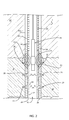
FIG. 2 illustrates a cross-sectional view of an embodiment of the shock wave generation device according to the invention located into a control screen nearby a sand formation; -
FIG. 3 schematically illustrates control particles arranged in a perforation extending into a sand formation; -
FIG. 4 schematically illustrates an embodiment of the shock wave generation device according to the invention; -
FIG. 5 illustrates an embodiment of the method according to the invention; -
FIG. 6 shows the evolution of pressure with time of a shock wave generated by a shock wave generation device according to the invention. - In the accompanying Figures, similar components or features, or both, may have the same or a similar reference label.
- The Specification, which includes the Summary of Invention, Brief Description of the Drawings and the Detailed Description of the Preferred Embodiments, and the appended Claims refer to particular features (including process or method steps) of the invention. Those of skill in the art understand that the invention includes all possible combinations and uses of particular features described in the Specification.
- Those of skill in the art understand that the invention is not limited to or by the description of embodiments given in the Specification. The inventive subject matter is not restricted except only in the spirit of the Specification and appended Claims.
- Those of skill in the art also understand that the terminology used for describing particular embodiments does not limit the scope or breadth of the invention. In interpreting the Specification and appended Claims, all terms should be interpreted in the broadest possible manner consistent with the context of each term. All technical and scientific terms used in the Specification and appended Claims have the same meaning as commonly understood by one of ordinary skill in the art to which this invention belongs unless defined otherwise.
- As used in the Specification and appended Claims, the singular forms "a", "an", and "the" include plural references unless the context clearly indicates otherwise. The verb "comprises" and its conjugated forms should be interpreted as referring to elements, components or steps in a non-exclusive manner. The referenced elements, components or steps may be present, utilized or combined with other elements, components or steps not expressly referenced. The verb "couple" and its conjugated forms means to complete any type of required junction, including electrical, mechanical or fluid, to form a singular object from two or more previously non-joined objects. If a first device couples to a second device, the connection can occur either directly or through a common connector. "Optionally" and its various forms means that the subsequently described event or circumstance may or may not occur. The description includes instances where the event or circumstance occurs and instances where it does not occur. "Operable" and its various forms means fit for its proper functioning and able to be used for its intended use.
- Spatial terms describe the relative position of an object or a group of objects relative to another object or group of objects. The spatial relationships apply along vertical and horizontal axes. Orientation and relational words including "uphole" and "downhole"; "above" and "below"; "up" and "down" and other like terms are for descriptive convenience and are not limiting unless otherwise indicated.
- Where the Specification or the appended Claims provide a range of values, it is understood that the interval encompasses each intervening value between the upper limit and the lower limit as well as the upper limit and the lower limit. The invention encompasses and bounds smaller ranges of the interval subject to any specific exclusion provided.
- Where the Specification and appended Claims reference a method comprising two or more defined steps, the defined steps can be carried out in any order or simultaneously except where the context excludes that possibility.
- The invention is described hereunder in reference to a well for producing formation fluids or gases such as e.g. oil wherein the formation is a sand formation. This does not limit the scope of the present invention which may be used with any type of formation wherein formation elements arranged on or between control particles of a formation control apparatus could prevent the passage of formation fluids or gases.
- As shown in
FIG. 1 , an exemplary wellbore 1 comprising asystem 5 according to the invention arranged in the wellbore 1. - The wellbore 1 comprises a borehole 10 which is drilled through the
earth 12 from adrilling rig 14 located at thesurface 16. Theborehole 10 defines awall 10a and is drilled down to a sand hydrocarbon-bearingsubterranean formation 18.Perforations 20 extend outwardly into theformation 18, creating therefore fractures within said formation near theborehole 10. - A
production tubing string 22 extends within the borehole 10 from thesurface 16. Anannulus 24 is defined between theproduction tubing string 22 and a wall of the surroundingborehole 10. A production flowbore 26 passes inside theproduction tubing string 22 for the transport of production fluids from theformation 18 to thesurface 16. -
FIG. 2 shows a detailed view of the wellbore 1 and theproduction tubing string 22 in theformation 18. A cementedwall 28 is built against theborehole wall 10a andperforations 20 extend outwardly through said cemented wall into theformation 18. - In order to prevent the passage of sand trough the
perforations 20 from theformation 18 into theproduction tubing string 22 when recovering hydrocarbons, a sand control apparatus is arranged in a portion of the borehole 10 located in theformation 18. - The sand control apparatus comprises a
control screen 30 and a plurality ofcontrol particles 32 arranged between the cementedwall 28 and saidcontrol screen 30. In another embodiment, the wellbore 1 may be deprived of cemented wall and be thus an open wellbore 1. - The
annulus 24 between the cementedwall 28 and thecontrol screen 30 is packed withcontrol particles 32 of a specific size designed to prevent the passage of formation sand and/or fines from theformation 18 to theproduction flowbore 26. - These
control particles 32 constitute a barrier or filter to migrating sand or formation particles while still permitting fluid flow from theformation 18. Thecontrol screen 30 and thecontrol particles 32 allow stabilizing theformation 18 while causing minimal impairment to well productivity. - In another embodiment,
control particles 32 could be used for example as proppant control particles. A proppant is a solid material, typically treated sand or man-made ceramic materials, designed to keep an induced hydraulic fracture open, during or following a fracturing treatment. - In addition to the use of sand control screens, other types of sand control equipment known from the person skilled in the art may be used in the
borehole 10, including liners (e.g., slotted liners, perforated liners, etc.), combinations of liners and screens, and other suitable apparatus. A cylindrical metallic casing could also be installed in the borehole 10 between thecontrol screen 30 and thewall 10a of theborehole 10. - A wide range of sizes and screen configurations are available to suit the characteristics of the
control particles 32 used. Similarly, a wide range of sizes ofcontrol particles 32 are available to suit the characteristics of the formation sand or reservoir particles. -
Control particles 32 may be for example gravels, sintered bauxite or ceramics such as e.g. CARBOLITE®. Ceramic control particles have a bulk density and specific gravity similar to sand, yet providing high flow capacity for enhanced production rates. Standard sizes for ceramic control particles are: 12/18, 16/20, 20/40 and 30/50 Mesh. - Turning now to
FIG. 3 , an exemplary embodiment of an arrangement ofcontrol particles 32 is shown. A significant amount of blockingelements 35, such as e.g. mineral deposits, fines and/or formation sand grains, is located on or in betweencontrol particles 32 prior to applying the method according to the invention. - In reference to
FIGS 1 and2 , thesystem 5 comprises a shockwave generation device 36, awireline 37 coupled to said shockwave generation device 36 for raising and lowering said shockwave generation device 36 in theproduction tubing string 22nearby control screen 30 andcontrol particles 32, avoltage source 38 located external of theborehole 10 and an electrical circuit within saidwireline 37 for connecting saidvoltage source 38 to the shockwave generation device 36. - As illustrated on
FIG. 4 , the shockwave generation device 36 is a source of electrohydraulic energy, which comprises amembrane 40 and anelectrical discharge unit 42. Themembrane 40 delimits achamber 44 which is filled with a shockwave transmitting liquid 46. Such amembrane 40 isolates the liquid 46 in thechamber 44 from theproduction tubing string 22 while maintaining acoustic coupling with saidproduction tubing string 22, improving the propagation of shockwaves while preventing external fluids from damaging theelectrical discharge unit 42. - In a preferred embodiment, the
membrane 40 is flexible in order to an efficient propagation of shock waves in many directions and prevent shock waves to bounce on it, allowing therefore an efficient conduction of the shock wave towardcontrol particles 32, in particular toward areas ofcontrol particles 32 which are accessible with difficulty or inaccessible to mechanical means such as e.g. brushes or chemical means such as e.g. acid. - To this end, the
membrane 40 may be made of fluorine rubber or fluoroelastomer with a relative elongation of at least 150 %, preferably at least 200% and being operable between -35°C and 250°C. - The
electrical discharge unit 42 is configured for generating a series of electrical discharges that propagate a series of shock waves into the shockwave transmitting liquid 46 and through themembrane 40 toward thecontrol particles 32 for removingblocking elements 35 from saidcontrol particles 32. Theelectrical discharge unit 42 may be configured to propagate shock waves radially or in a predetermined direction. - In this example, and as already describes in
US patent 4,345,650 issued to Wesley orUS patent 6,227,293 issued to Huffman, incorporated hereby by reference, theelectrical discharge unit 42 comprises apower conversion unit 48, apower storage unit 50, adischarge control unit 52 and adischarge system 54. Thedischarge system 54 comprises afirst electrode 56 and asecond electrode 58 configured for triggering an electrical discharge. - The
discharge system 54 comprises a plurality of capacitors (not represented) for storage of electrical energy configured for generating one or a plurality of electrical discharges into the shockwave transmitting liquid 46. Thechamber 44 is delimited by themembrane 40 around thedischarge system 54 which is filled with the shockwave transmitting liquid 46, allowing transmitting shock waves through themembrane 40 toward thecontrol particles 32. - Electrical power is supplied by the
low voltage source 38 at a steady and relatively low power from thesurface 16 through thewireline 37 to the downhole shockwave generation device 36. Thepower conversion unit 48 comprises suitable circuitry for charging of the capacitors in thepower storage unit 50. Timing of the discharge of the energy in the power from thepower storage unit 50 through thedischarge system 54 is accomplished using thedischarge control unit 52. - In a preferred embodiment, the
discharge control unit 52 is a switch, which discharges when the voltage reaches a predefined threshold. Upon discharge of the capacitors in the power storage section through thefirst electrodes 56 and thesecond electrode 58 of thedischarge control unit 52, electrohydraulic shock waves 60 (in reference toFIG. 2 ) are transmitted to thecontrol particles 32 for cleaning saidcontrol particle 32 . - Other designs of
discharge system 54 are disclosed inUS patent 6,227,293 issued to Huffman which is included hereby reference. According to the electrohydraulic effect, an electrical discharge is discharged in a very short time (few micro seconds) in the shockwave transmitting liquid 46. - The invention is describes in its application to removing deposits, in particular mineral deposits, and/or fines from
control particles 32 and/or or redistributing deposits and/or fines located in betweencontrol particles 32, saidcontrol particles 32 being arranged inannulus 24 andperforations 20 for preventing the passage of sand formation when collecting formation fluids. -
FIG. 5 illustrates an embodiment of the method for cleaningcontrol particles 32 arranged in aborehole 10 of asubterranean formation 18 according to the invention. Prior to operate the method according to the invention, the sand control apparatus is at least partially blocked with blocking elements 35 (as described here above in reference toFIG. 3 ). - In a first step S1, a series of shock waves is generated into the
control screen 30 nearby thecontrol particles 32. In this example, the series of shock waves is generated into the shockwave transmitting liquid 46 of the shockwave generating device 36. - Then, in a second step S2, the series of shock waves propagates through the
membrane 40 toward thecontrol screen 30 andcontrol particles 32 for removingblocking elements 35 located on or in between saidcontrol particles 32. - Preferably, the series of shock waves comprises at least ten shock waves, for example propagated at a periodic interval of time, e.g. every 5 to 20 seconds. A plurality of series may be advantageously repeated at different heights in the
production tubing string 22 to remove blockingelements 35 in areas which would be inaccessible to mechanical or chemical means such as e.g. acid. -
FIG. 6 shows the variation of pressure with timenearby control particles 32. Firstly, the pressure generated by the shock wave increases in a very short time dT, e.g. a few microseconds, until a maximum P1. Such a peak phase characterizes a compression of blockingelements 35. Then, the pressure generated by the shock wave decreases to a negative value P2 for a significant amount of time, e.g. a few milliseconds. - This second phase characterizes a traction effort applied on blocking elements, which allows breaking said blocking
elements 35, in particular in areas which are accessible with difficulty or inaccessible to mechanical or chemical means. - Such an traction effort is improved by the quality of propagation of the shock wave trough the shock
wave transmitting liquid 46 and themembrane 40, allowing removingblocking elements 35 efficiently. - Embodiments include many additional standard components or equipment that enables and makes operable the described device, process, method and system.
- Operation, control and performance of portions of or entire steps of a process or method can occur through human interaction, pre-programmed computer control and response systems, or combinations thereof.
- Examples of specific embodiments facilitate a better understanding of deposits removing method and device. In no way should the Examples limit or define the scope of the invention.
- This method shows good results as at least 80 % of blocking
elements 35 are removed from or betweencontrol particles 32. - The invention is not limited to the described embodiment and can be applied to all type of formation fluids or gases transportation means.
Claims (15)
- A method for cleaning control particles (32) in a wellbore (1) of a subterranean formation (18) to improve the recovery of formation fluids and/or gases, said wellbore (1) comprising a wall (10a) defining a borehole (10), at least one control equipment (30) arranged into said borehole (10) and a plurality of control particles (32) arranged between said control equipment (30) and said wall (10a), said method comprising the steps of generating at least one shock wave (60) nearby said control equipment (30) and propagating said at least one shock wave (60) through said control equipment (30) toward said control particles (32) for cleaning said control particles (32).
- A method according to claim 1 for removing mineral deposits from ceramic control particles (32) in a wellbore (1) of a subterranean formation (18) to improve the recovery of formation fluids and/or gases.
- A method according to claim 1 or 2, wherein a series of at least ten shock waves (60) is generated for efficiently removing deposits from the control particles (32).
- A method according to the preceding claim, wherein a plurality of series of shock waves (60) is generated, each series of shock waves (60) being generated at different locations near the control equipment (30).
- A method according to any of the preceding claims, wherein the at least one shock wave (60) is generated in a transmitting liquid (36) which is at least partially delimited by a membrane (40) and the at least one shock wave (60) is propagated through said membrane (40) toward the control particles (32) for cleaning said control particles (32).
- A shock wave generating device (36) for cleaning control particles (32) in a wellbore (1) of a subterranean formation (18) to improve the recovery of formation fluids and/or gases, said wellbore (1) comprising a wall (10a) defining a borehole (10), at least one control equipment arranged into said borehole (10) and a plurality of control particles (32) arranged between said control equipment (30) and said wall (10a), said device comprising:- a chamber (44) which is partially filled with a shock wave transmitting liquid (46) and which is adapted to be arranged into said borehole nearby said control equipment (30); and- an electrical discharge unit (42) for generating at least one electrical discharge that propagates at least one shock wave (60) into said shock wave transmitting liquid (46) through said control equipment (30) and said control particles (32) for cleaning said control particles (32).
- A shock wave generating device (36) according to claim 6, wherein the chamber (44) is at least partially delimited by a membrane (40) and the electrical discharge unit (42) is configured for generating at least one electrical discharge that propagates at least one shock wave (60) into said shock wave transmitting liquid (46) through said membrane (40) nearby said control equipment (30) for cleaning from control particles (32).
- A shock wave generation device (36) according to the preceding claim, wherein the membrane (40) is deformable in order to conduct efficiently the shock wave toward the control particles (32).
- A shock wave generation device (36) according to the preceding claim, wherein the membrane (40) is made of fluorinated rubber or other fluoroelastomer.
- A shock wave generation device (36) according to any of the preceding claims 6 to 9, wherein the electrical discharge unit (42) comprises a power conversion unit (48), a power storage unit (50), a discharge control unit (52) and a discharge system (54).
- A shock wave generation device (36) according to the preceding claim, wherein the discharge system (54) comprises a first electrode (56) and a second electrode (58) for generating a high voltage arc in the shock wave transmitting liquid (46).
- A shock wave generation device (36) according to any of the preceding claims 6 to 11, wherein the electrical discharge unit (42) is configured for generating at least one electrical discharge that propagates at least one shock wave (60) radially.
- A shock wave generation device (36) according to any of the preceding claims 6 to 11, wherein the electrical discharge unit (42) is configured for generating at least one electrical discharge that propagates at least one shock wave (60) in a predetermined direction.
- A system (5) for cleaning control particles (32) in a wellbore (1) of a subterranean formation (18) to improve the recovery of formation fluids and/or gases, said wellbore (1) comprising a wall (10a) defining a borehole (10), at least one control equipment (30) arranged into said borehole (10) and a plurality of control particles (32) arranged between said control equipment (30) and said wall (10a), said system (5) comprising:- a shock wave generation device (36) according to any of the claims 6 to 13;- a wireline (37) coupled to said shock wave generation device (36) for inserting said shock wave generation device (36) in the borehole (10) nearby said control equipment (30);- a voltage source (38) located external of the borehole (10); and- an electrical circuit within said wireline (37) for connecting said voltage source (38) to the shock wave generation device (36).
- A wellbore (1) for recovering formation fluids or gases from a subterranean formation (18), said wellbore (1) comprising a wall (10a) defining a borehole (10), at least one control equipment (30) arranged into said borehole (10), a plurality of control particles (32) arranged between said control equipment (30) and said wall (10a), and a device according to any of the claims 6 to 13.
Priority Applications (1)
| Application Number | Priority Date | Filing Date | Title |
|---|---|---|---|
| EP14178419.9A EP2977545B1 (en) | 2014-07-24 | 2014-07-24 | Method and device for cleaning control particles in a wellbore |
Applications Claiming Priority (1)
| Application Number | Priority Date | Filing Date | Title |
|---|---|---|---|
| EP14178419.9A EP2977545B1 (en) | 2014-07-24 | 2014-07-24 | Method and device for cleaning control particles in a wellbore |
Publications (2)
| Publication Number | Publication Date |
|---|---|
| EP2977545A1 true EP2977545A1 (en) | 2016-01-27 |
| EP2977545B1 EP2977545B1 (en) | 2019-06-05 |
Family
ID=51224785
Family Applications (1)
| Application Number | Title | Priority Date | Filing Date |
|---|---|---|---|
| EP14178419.9A Active EP2977545B1 (en) | 2014-07-24 | 2014-07-24 | Method and device for cleaning control particles in a wellbore |
Country Status (1)
| Country | Link |
|---|---|
| EP (1) | EP2977545B1 (en) |
Cited By (4)
| Publication number | Priority date | Publication date | Assignee | Title |
|---|---|---|---|---|
| US20150308233A1 (en) * | 2014-04-28 | 2015-10-29 | Blue Spark Energy Inc. | Method and device for removing deposits from a formation fluid or gas transportation means |
| EP3461990A1 (en) * | 2017-10-02 | 2019-04-03 | Blue Spark Energy Inc. | Device and method for cleaning a wellbore equipment |
| US20190100981A1 (en) * | 2017-10-02 | 2019-04-04 | Blue Spark Energy Inc. | Device and method for cleaning a wellbore equipment |
| CN113789694A (en) * | 2021-08-21 | 2021-12-14 | 杭州萧山水利建筑工程有限公司 | Assembled environmental protection concrete road that permeates water |
Citations (10)
| Publication number | Priority date | Publication date | Assignee | Title |
|---|---|---|---|---|
| US4345650A (en) | 1980-04-11 | 1982-08-24 | Wesley Richard H | Process and apparatus for electrohydraulic recovery of crude oil |
| US4997044A (en) * | 1989-12-01 | 1991-03-05 | Stack Walter E | Apparatus for generating hydraulic shock waves in a well |
| US5004050A (en) * | 1988-05-20 | 1991-04-02 | Sizonenko Olga N | Method for well stimulation in the process of oil production and device for carrying same into effect |
| US5579845A (en) * | 1995-02-07 | 1996-12-03 | William C. Frazier | Method for improved water well production |
| US6227293B1 (en) | 2000-02-09 | 2001-05-08 | Conoco Inc. | Process and apparatus for coupled electromagnetic and acoustic stimulation of crude oil reservoirs using pulsed power electrohydraulic and electromagnetic discharge |
| US20020153135A1 (en) * | 2001-04-24 | 2002-10-24 | Layne Christensen Company | Method and apparatus for stimulating well production |
| US20050061503A1 (en) | 2002-09-27 | 2005-03-24 | Misselbrook John Gordon | Method for cleaning gravel packs |
| US20070187090A1 (en) | 2006-02-15 | 2007-08-16 | Halliburton Energy Services, Inc. | Methods of cleaning sand control screens and gravel packs |
| US7896080B1 (en) | 2006-09-08 | 2011-03-01 | Larry Watters | Method of improving hydrocarbon production from a gravel packed oil and gas well |
| US20140008073A1 (en) * | 2011-03-14 | 2014-01-09 | Total S.A. | Electrical and static fracturing of a reservoir |
Family Cites Families (1)
| Publication number | Priority date | Publication date | Assignee | Title |
|---|---|---|---|---|
| EP2940244B1 (en) * | 2014-04-28 | 2019-07-24 | Blue Spark Energy Inc. | Method and device for removing deposits from a formation fluid or gas transportation means |
-
2014
- 2014-07-24 EP EP14178419.9A patent/EP2977545B1/en active Active
Patent Citations (10)
| Publication number | Priority date | Publication date | Assignee | Title |
|---|---|---|---|---|
| US4345650A (en) | 1980-04-11 | 1982-08-24 | Wesley Richard H | Process and apparatus for electrohydraulic recovery of crude oil |
| US5004050A (en) * | 1988-05-20 | 1991-04-02 | Sizonenko Olga N | Method for well stimulation in the process of oil production and device for carrying same into effect |
| US4997044A (en) * | 1989-12-01 | 1991-03-05 | Stack Walter E | Apparatus for generating hydraulic shock waves in a well |
| US5579845A (en) * | 1995-02-07 | 1996-12-03 | William C. Frazier | Method for improved water well production |
| US6227293B1 (en) | 2000-02-09 | 2001-05-08 | Conoco Inc. | Process and apparatus for coupled electromagnetic and acoustic stimulation of crude oil reservoirs using pulsed power electrohydraulic and electromagnetic discharge |
| US20020153135A1 (en) * | 2001-04-24 | 2002-10-24 | Layne Christensen Company | Method and apparatus for stimulating well production |
| US20050061503A1 (en) | 2002-09-27 | 2005-03-24 | Misselbrook John Gordon | Method for cleaning gravel packs |
| US20070187090A1 (en) | 2006-02-15 | 2007-08-16 | Halliburton Energy Services, Inc. | Methods of cleaning sand control screens and gravel packs |
| US7896080B1 (en) | 2006-09-08 | 2011-03-01 | Larry Watters | Method of improving hydrocarbon production from a gravel packed oil and gas well |
| US20140008073A1 (en) * | 2011-03-14 | 2014-01-09 | Total S.A. | Electrical and static fracturing of a reservoir |
Cited By (6)
| Publication number | Priority date | Publication date | Assignee | Title |
|---|---|---|---|---|
| US20150308233A1 (en) * | 2014-04-28 | 2015-10-29 | Blue Spark Energy Inc. | Method and device for removing deposits from a formation fluid or gas transportation means |
| US9890613B2 (en) * | 2014-04-28 | 2018-02-13 | Blue Spark Energy Inc. | Method and device for removing deposits from a formation fluid or gas transportation means |
| EP3461990A1 (en) * | 2017-10-02 | 2019-04-03 | Blue Spark Energy Inc. | Device and method for cleaning a wellbore equipment |
| US20190100981A1 (en) * | 2017-10-02 | 2019-04-04 | Blue Spark Energy Inc. | Device and method for cleaning a wellbore equipment |
| US10865622B2 (en) * | 2017-10-02 | 2020-12-15 | Blue Spark Energy Inc. | Device and method for cleaning a wellbore equipment |
| CN113789694A (en) * | 2021-08-21 | 2021-12-14 | 杭州萧山水利建筑工程有限公司 | Assembled environmental protection concrete road that permeates water |
Also Published As
| Publication number | Publication date |
|---|---|
| EP2977545B1 (en) | 2019-06-05 |
Similar Documents
| Publication | Publication Date | Title |
|---|---|---|
| US9810041B2 (en) | Method and device for cleaning control particles in a wellbore | |
| US7882895B2 (en) | Method for impulse stimulation of oil and gas well production | |
| US8640772B2 (en) | Enhanced geothermal systems and reservoir optimization | |
| US8082989B2 (en) | Method for impulse stimulation of oil and gas well production | |
| US10309202B2 (en) | Fracturing treatment of subterranean formations using shock waves | |
| EP2977545B1 (en) | Method and device for cleaning control particles in a wellbore | |
| US9890613B2 (en) | Method and device for removing deposits from a formation fluid or gas transportation means | |
| RU2600249C1 (en) | Method and device of impact on oil-saturated formations and bottomhole zone of horizontal well | |
| CA2862556A1 (en) | Method to underdisplace hydraulic fractures in horizontal or deviated well | |
| US10865622B2 (en) | Device and method for cleaning a wellbore equipment | |
| EP2940244B1 (en) | Method and device for removing deposits from a formation fluid or gas transportation means | |
| US7059411B2 (en) | Process of using a propellant treatment and continuous foam removal of well debris and apparatus therefore | |
| US9567828B2 (en) | Apparatus and method for sealing a portion of a component disposed in a wellbore | |
| US20180245440A1 (en) | Methods for Refracturing a Subterranean Formation | |
| CA2930355C (en) | Method for sealing an opening of a wellbore equipment | |
| Bakker et al. | The new dynamics of underbalanced perforating | |
| US20050045336A1 (en) | Propellant treatment and continuous foam removal of well debris | |
| EP3461990B1 (en) | Device and method for cleaning a wellbore equipment | |
| EP3098379B1 (en) | Method for sealing an opening of a wellbore equipment | |
| US11767738B1 (en) | Use of pressure wave resonators in downhole operations | |
| CA2447556C (en) | Propellant treatment and continuous foam removal of well debris | |
| Pinto et al. | Coiled Tubing and a Fluidic Oscillator Used as an Aid for Selective Placement Technique to Wells in Huila, Colombia | |
| CA2438640A1 (en) | Propellant treatment and continuous foam removal of well debris |
Legal Events
| Date | Code | Title | Description |
|---|---|---|---|
| PUAI | Public reference made under article 153(3) epc to a published international application that has entered the european phase |
Free format text: ORIGINAL CODE: 0009012 |
|
| AK | Designated contracting states |
Kind code of ref document: A1 Designated state(s): AL AT BE BG CH CY CZ DE DK EE ES FI FR GB GR HR HU IE IS IT LI LT LU LV MC MK MT NL NO PL PT RO RS SE SI SK SM TR |
|
| AX | Request for extension of the european patent |
Extension state: BA ME |
|
| 17P | Request for examination filed |
Effective date: 20160622 |
|
| RBV | Designated contracting states (corrected) |
Designated state(s): AL AT BE BG CH CY CZ DE DK EE ES FI FR GB GR HR HU IE IS IT LI LT LU LV MC MK MT NL NO PL PT RO RS SE SI SK SM TR |
|
| STAA | Information on the status of an ep patent application or granted ep patent |
Free format text: STATUS: EXAMINATION IS IN PROGRESS |
|
| 17Q | First examination report despatched |
Effective date: 20161222 |
|
| GRAP | Despatch of communication of intention to grant a patent |
Free format text: ORIGINAL CODE: EPIDOSNIGR1 |
|
| STAA | Information on the status of an ep patent application or granted ep patent |
Free format text: STATUS: GRANT OF PATENT IS INTENDED |
|
| RIC1 | Information provided on ipc code assigned before grant |
Ipc: E21B 37/08 20060101AFI20190301BHEP Ipc: B08B 7/02 20060101ALI20190301BHEP |
|
| INTG | Intention to grant announced |
Effective date: 20190322 |
|
| RIN1 | Information on inventor provided before grant (corrected) |
Inventor name: CARROLL, SHAWN Inventor name: PARKER, TODD Inventor name: SKIBISNKI, DAN |
|
| GRAS | Grant fee paid |
Free format text: ORIGINAL CODE: EPIDOSNIGR3 |
|
| GRAA | (expected) grant |
Free format text: ORIGINAL CODE: 0009210 |
|
| STAA | Information on the status of an ep patent application or granted ep patent |
Free format text: STATUS: THE PATENT HAS BEEN GRANTED |
|
| AK | Designated contracting states |
Kind code of ref document: B1 Designated state(s): AL AT BE BG CH CY CZ DE DK EE ES FI FR GB GR HR HU IE IS IT LI LT LU LV MC MK MT NL NO PL PT RO RS SE SI SK SM TR |
|
| REG | Reference to a national code |
Ref country code: GB Ref legal event code: FG4D |
|
| REG | Reference to a national code |
Ref country code: CH Ref legal event code: EP |
|
| REG | Reference to a national code |
Ref country code: AT Ref legal event code: REF Ref document number: 1140151 Country of ref document: AT Kind code of ref document: T Effective date: 20190615 |
|
| REG | Reference to a national code |
Ref country code: IE Ref legal event code: FG4D |
|
| REG | Reference to a national code |
Ref country code: DE Ref legal event code: R096 Ref document number: 602014047755 Country of ref document: DE |
|
| REG | Reference to a national code |
Ref country code: NO Ref legal event code: T2 Effective date: 20190605 |
|
| REG | Reference to a national code |
Ref country code: NL Ref legal event code: MP Effective date: 20190605 |
|
| REG | Reference to a national code |
Ref country code: LT Ref legal event code: MG4D |
|
| PG25 | Lapsed in a contracting state [announced via postgrant information from national office to epo] |
Ref country code: AL Free format text: LAPSE BECAUSE OF FAILURE TO SUBMIT A TRANSLATION OF THE DESCRIPTION OR TO PAY THE FEE WITHIN THE PRESCRIBED TIME-LIMIT Effective date: 20190605 Ref country code: ES Free format text: LAPSE BECAUSE OF FAILURE TO SUBMIT A TRANSLATION OF THE DESCRIPTION OR TO PAY THE FEE WITHIN THE PRESCRIBED TIME-LIMIT Effective date: 20190605 Ref country code: SE Free format text: LAPSE BECAUSE OF FAILURE TO SUBMIT A TRANSLATION OF THE DESCRIPTION OR TO PAY THE FEE WITHIN THE PRESCRIBED TIME-LIMIT Effective date: 20190605 Ref country code: HR Free format text: LAPSE BECAUSE OF FAILURE TO SUBMIT A TRANSLATION OF THE DESCRIPTION OR TO PAY THE FEE WITHIN THE PRESCRIBED TIME-LIMIT Effective date: 20190605 Ref country code: LT Free format text: LAPSE BECAUSE OF FAILURE TO SUBMIT A TRANSLATION OF THE DESCRIPTION OR TO PAY THE FEE WITHIN THE PRESCRIBED TIME-LIMIT Effective date: 20190605 Ref country code: FI Free format text: LAPSE BECAUSE OF FAILURE TO SUBMIT A TRANSLATION OF THE DESCRIPTION OR TO PAY THE FEE WITHIN THE PRESCRIBED TIME-LIMIT Effective date: 20190605 |
|
| PG25 | Lapsed in a contracting state [announced via postgrant information from national office to epo] |
Ref country code: LV Free format text: LAPSE BECAUSE OF FAILURE TO SUBMIT A TRANSLATION OF THE DESCRIPTION OR TO PAY THE FEE WITHIN THE PRESCRIBED TIME-LIMIT Effective date: 20190605 Ref country code: RS Free format text: LAPSE BECAUSE OF FAILURE TO SUBMIT A TRANSLATION OF THE DESCRIPTION OR TO PAY THE FEE WITHIN THE PRESCRIBED TIME-LIMIT Effective date: 20190605 Ref country code: BG Free format text: LAPSE BECAUSE OF FAILURE TO SUBMIT A TRANSLATION OF THE DESCRIPTION OR TO PAY THE FEE WITHIN THE PRESCRIBED TIME-LIMIT Effective date: 20190905 Ref country code: GR Free format text: LAPSE BECAUSE OF FAILURE TO SUBMIT A TRANSLATION OF THE DESCRIPTION OR TO PAY THE FEE WITHIN THE PRESCRIBED TIME-LIMIT Effective date: 20190906 |
|
| REG | Reference to a national code |
Ref country code: AT Ref legal event code: MK05 Ref document number: 1140151 Country of ref document: AT Kind code of ref document: T Effective date: 20190605 |
|
| PG25 | Lapsed in a contracting state [announced via postgrant information from national office to epo] |
Ref country code: PT Free format text: LAPSE BECAUSE OF FAILURE TO SUBMIT A TRANSLATION OF THE DESCRIPTION OR TO PAY THE FEE WITHIN THE PRESCRIBED TIME-LIMIT Effective date: 20191007 Ref country code: SK Free format text: LAPSE BECAUSE OF FAILURE TO SUBMIT A TRANSLATION OF THE DESCRIPTION OR TO PAY THE FEE WITHIN THE PRESCRIBED TIME-LIMIT Effective date: 20190605 Ref country code: EE Free format text: LAPSE BECAUSE OF FAILURE TO SUBMIT A TRANSLATION OF THE DESCRIPTION OR TO PAY THE FEE WITHIN THE PRESCRIBED TIME-LIMIT Effective date: 20190605 Ref country code: AT Free format text: LAPSE BECAUSE OF FAILURE TO SUBMIT A TRANSLATION OF THE DESCRIPTION OR TO PAY THE FEE WITHIN THE PRESCRIBED TIME-LIMIT Effective date: 20190605 Ref country code: CZ Free format text: LAPSE BECAUSE OF FAILURE TO SUBMIT A TRANSLATION OF THE DESCRIPTION OR TO PAY THE FEE WITHIN THE PRESCRIBED TIME-LIMIT Effective date: 20190605 Ref country code: NL Free format text: LAPSE BECAUSE OF FAILURE TO SUBMIT A TRANSLATION OF THE DESCRIPTION OR TO PAY THE FEE WITHIN THE PRESCRIBED TIME-LIMIT Effective date: 20190605 Ref country code: RO Free format text: LAPSE BECAUSE OF FAILURE TO SUBMIT A TRANSLATION OF THE DESCRIPTION OR TO PAY THE FEE WITHIN THE PRESCRIBED TIME-LIMIT Effective date: 20190605 |
|
| REG | Reference to a national code |
Ref country code: DE Ref legal event code: R119 Ref document number: 602014047755 Country of ref document: DE |
|
| PG25 | Lapsed in a contracting state [announced via postgrant information from national office to epo] |
Ref country code: SM Free format text: LAPSE BECAUSE OF FAILURE TO SUBMIT A TRANSLATION OF THE DESCRIPTION OR TO PAY THE FEE WITHIN THE PRESCRIBED TIME-LIMIT Effective date: 20190605 Ref country code: IT Free format text: LAPSE BECAUSE OF FAILURE TO SUBMIT A TRANSLATION OF THE DESCRIPTION OR TO PAY THE FEE WITHIN THE PRESCRIBED TIME-LIMIT Effective date: 20190605 Ref country code: IS Free format text: LAPSE BECAUSE OF FAILURE TO SUBMIT A TRANSLATION OF THE DESCRIPTION OR TO PAY THE FEE WITHIN THE PRESCRIBED TIME-LIMIT Effective date: 20191005 |
|
| REG | Reference to a national code |
Ref country code: CH Ref legal event code: PL |
|
| PG25 | Lapsed in a contracting state [announced via postgrant information from national office to epo] |
Ref country code: TR Free format text: LAPSE BECAUSE OF FAILURE TO SUBMIT A TRANSLATION OF THE DESCRIPTION OR TO PAY THE FEE WITHIN THE PRESCRIBED TIME-LIMIT Effective date: 20190605 Ref country code: MC Free format text: LAPSE BECAUSE OF FAILURE TO SUBMIT A TRANSLATION OF THE DESCRIPTION OR TO PAY THE FEE WITHIN THE PRESCRIBED TIME-LIMIT Effective date: 20190605 |
|
| PLBE | No opposition filed within time limit |
Free format text: ORIGINAL CODE: 0009261 |
|
| STAA | Information on the status of an ep patent application or granted ep patent |
Free format text: STATUS: NO OPPOSITION FILED WITHIN TIME LIMIT |
|
| REG | Reference to a national code |
Ref country code: BE Ref legal event code: MM Effective date: 20190731 |
|
| PG25 | Lapsed in a contracting state [announced via postgrant information from national office to epo] |
Ref country code: PL Free format text: LAPSE BECAUSE OF FAILURE TO SUBMIT A TRANSLATION OF THE DESCRIPTION OR TO PAY THE FEE WITHIN THE PRESCRIBED TIME-LIMIT Effective date: 20190605 Ref country code: DE Free format text: LAPSE BECAUSE OF NON-PAYMENT OF DUE FEES Effective date: 20200201 Ref country code: DK Free format text: LAPSE BECAUSE OF FAILURE TO SUBMIT A TRANSLATION OF THE DESCRIPTION OR TO PAY THE FEE WITHIN THE PRESCRIBED TIME-LIMIT Effective date: 20190605 |
|
| 26N | No opposition filed |
Effective date: 20200306 |
|
| PG25 | Lapsed in a contracting state [announced via postgrant information from national office to epo] |
Ref country code: LI Free format text: LAPSE BECAUSE OF NON-PAYMENT OF DUE FEES Effective date: 20190731 Ref country code: SI Free format text: LAPSE BECAUSE OF FAILURE TO SUBMIT A TRANSLATION OF THE DESCRIPTION OR TO PAY THE FEE WITHIN THE PRESCRIBED TIME-LIMIT Effective date: 20190605 Ref country code: BE Free format text: LAPSE BECAUSE OF NON-PAYMENT OF DUE FEES Effective date: 20190731 Ref country code: LU Free format text: LAPSE BECAUSE OF NON-PAYMENT OF DUE FEES Effective date: 20190724 Ref country code: CH Free format text: LAPSE BECAUSE OF NON-PAYMENT OF DUE FEES Effective date: 20190731 |
|
| PG25 | Lapsed in a contracting state [announced via postgrant information from national office to epo] |
Ref country code: IE Free format text: LAPSE BECAUSE OF NON-PAYMENT OF DUE FEES Effective date: 20190724 |
|
| PG25 | Lapsed in a contracting state [announced via postgrant information from national office to epo] |
Ref country code: CY Free format text: LAPSE BECAUSE OF FAILURE TO SUBMIT A TRANSLATION OF THE DESCRIPTION OR TO PAY THE FEE WITHIN THE PRESCRIBED TIME-LIMIT Effective date: 20190605 |
|
| PG25 | Lapsed in a contracting state [announced via postgrant information from national office to epo] |
Ref country code: HU Free format text: LAPSE BECAUSE OF FAILURE TO SUBMIT A TRANSLATION OF THE DESCRIPTION OR TO PAY THE FEE WITHIN THE PRESCRIBED TIME-LIMIT; INVALID AB INITIO Effective date: 20140724 Ref country code: MT Free format text: LAPSE BECAUSE OF FAILURE TO SUBMIT A TRANSLATION OF THE DESCRIPTION OR TO PAY THE FEE WITHIN THE PRESCRIBED TIME-LIMIT Effective date: 20190605 |
|
| PG25 | Lapsed in a contracting state [announced via postgrant information from national office to epo] |
Ref country code: MK Free format text: LAPSE BECAUSE OF FAILURE TO SUBMIT A TRANSLATION OF THE DESCRIPTION OR TO PAY THE FEE WITHIN THE PRESCRIBED TIME-LIMIT Effective date: 20190605 |
|
| PGFP | Annual fee paid to national office [announced via postgrant information from national office to epo] |
Ref country code: NO Payment date: 20230721 Year of fee payment: 10 Ref country code: GB Payment date: 20230720 Year of fee payment: 10 |
|
| PGFP | Annual fee paid to national office [announced via postgrant information from national office to epo] |
Ref country code: FR Payment date: 20230725 Year of fee payment: 10 |