EP2977333B1 - Dispensing adaptor for one-component polyurethane foam - Google Patents
Dispensing adaptor for one-component polyurethane foam Download PDFInfo
- Publication number
- EP2977333B1 EP2977333B1 EP13878923.5A EP13878923A EP2977333B1 EP 2977333 B1 EP2977333 B1 EP 2977333B1 EP 13878923 A EP13878923 A EP 13878923A EP 2977333 B1 EP2977333 B1 EP 2977333B1
- Authority
- EP
- European Patent Office
- Prior art keywords
- lever
- adaptor
- dispensing
- extended
- polyurethane foam
- Prior art date
- Legal status (The legal status is an assumption and is not a legal conclusion. Google has not performed a legal analysis and makes no representation as to the accuracy of the status listed.)
- Active
Links
Images



Classifications
-
- B—PERFORMING OPERATIONS; TRANSPORTING
- B65—CONVEYING; PACKING; STORING; HANDLING THIN OR FILAMENTARY MATERIAL
- B65D—CONTAINERS FOR STORAGE OR TRANSPORT OF ARTICLES OR MATERIALS, e.g. BAGS, BARRELS, BOTTLES, BOXES, CANS, CARTONS, CRATES, DRUMS, JARS, TANKS, HOPPERS, FORWARDING CONTAINERS; ACCESSORIES, CLOSURES, OR FITTINGS THEREFOR; PACKAGING ELEMENTS; PACKAGES
- B65D83/00—Containers or packages with special means for dispensing contents
- B65D83/14—Containers for dispensing liquid or semi-liquid contents by internal gaseous pressure, i.e. aerosol containers comprising propellant
- B65D83/28—Nozzles, nozzle fittings or accessories specially adapted therefor
- B65D83/30—Nozzles, nozzle fittings or accessories specially adapted therefor for guiding the flow of the dispensed content, e.g. funnels or hoods
- B65D83/303—Nozzles, nozzle fittings or accessories specially adapted therefor for guiding the flow of the dispensed content, e.g. funnels or hoods using extension tubes located in or at the nozzle outlets
-
- B—PERFORMING OPERATIONS; TRANSPORTING
- B65—CONVEYING; PACKING; STORING; HANDLING THIN OR FILAMENTARY MATERIAL
- B65D—CONTAINERS FOR STORAGE OR TRANSPORT OF ARTICLES OR MATERIALS, e.g. BAGS, BARRELS, BOTTLES, BOXES, CANS, CARTONS, CRATES, DRUMS, JARS, TANKS, HOPPERS, FORWARDING CONTAINERS; ACCESSORIES, CLOSURES, OR FITTINGS THEREFOR; PACKAGING ELEMENTS; PACKAGES
- B65D83/00—Containers or packages with special means for dispensing contents
- B65D83/14—Containers for dispensing liquid or semi-liquid contents by internal gaseous pressure, i.e. aerosol containers comprising propellant
- B65D83/16—Actuating means
-
- B—PERFORMING OPERATIONS; TRANSPORTING
- B65—CONVEYING; PACKING; STORING; HANDLING THIN OR FILAMENTARY MATERIAL
- B65D—CONTAINERS FOR STORAGE OR TRANSPORT OF ARTICLES OR MATERIALS, e.g. BAGS, BARRELS, BOTTLES, BOXES, CANS, CARTONS, CRATES, DRUMS, JARS, TANKS, HOPPERS, FORWARDING CONTAINERS; ACCESSORIES, CLOSURES, OR FITTINGS THEREFOR; PACKAGING ELEMENTS; PACKAGES
- B65D83/00—Containers or packages with special means for dispensing contents
- B65D83/14—Containers for dispensing liquid or semi-liquid contents by internal gaseous pressure, i.e. aerosol containers comprising propellant
- B65D83/141—Containers for dispensing liquid or semi-liquid contents by internal gaseous pressure, i.e. aerosol containers comprising propellant specially adapted for specific contents or propellants
-
- B—PERFORMING OPERATIONS; TRANSPORTING
- B65—CONVEYING; PACKING; STORING; HANDLING THIN OR FILAMENTARY MATERIAL
- B65D—CONTAINERS FOR STORAGE OR TRANSPORT OF ARTICLES OR MATERIALS, e.g. BAGS, BARRELS, BOTTLES, BOXES, CANS, CARTONS, CRATES, DRUMS, JARS, TANKS, HOPPERS, FORWARDING CONTAINERS; ACCESSORIES, CLOSURES, OR FITTINGS THEREFOR; PACKAGING ELEMENTS; PACKAGES
- B65D83/00—Containers or packages with special means for dispensing contents
- B65D83/14—Containers for dispensing liquid or semi-liquid contents by internal gaseous pressure, i.e. aerosol containers comprising propellant
- B65D83/16—Actuating means
- B65D83/18—Hand lever actuators
- B65D83/182—Hand lever actuators combined with hand grips
-
- B—PERFORMING OPERATIONS; TRANSPORTING
- B65—CONVEYING; PACKING; STORING; HANDLING THIN OR FILAMENTARY MATERIAL
- B65D—CONTAINERS FOR STORAGE OR TRANSPORT OF ARTICLES OR MATERIALS, e.g. BAGS, BARRELS, BOTTLES, BOXES, CANS, CARTONS, CRATES, DRUMS, JARS, TANKS, HOPPERS, FORWARDING CONTAINERS; ACCESSORIES, CLOSURES, OR FITTINGS THEREFOR; PACKAGING ELEMENTS; PACKAGES
- B65D83/00—Containers or packages with special means for dispensing contents
- B65D83/14—Containers for dispensing liquid or semi-liquid contents by internal gaseous pressure, i.e. aerosol containers comprising propellant
- B65D83/16—Actuating means
- B65D83/20—Actuator caps
- B65D83/206—Actuator caps comprising cantilevered actuating elements, e.g. levers pivoting about living hinges
-
- B—PERFORMING OPERATIONS; TRANSPORTING
- B65—CONVEYING; PACKING; STORING; HANDLING THIN OR FILAMENTARY MATERIAL
- B65D—CONTAINERS FOR STORAGE OR TRANSPORT OF ARTICLES OR MATERIALS, e.g. BAGS, BARRELS, BOTTLES, BOXES, CANS, CARTONS, CRATES, DRUMS, JARS, TANKS, HOPPERS, FORWARDING CONTAINERS; ACCESSORIES, CLOSURES, OR FITTINGS THEREFOR; PACKAGING ELEMENTS; PACKAGES
- B65D83/00—Containers or packages with special means for dispensing contents
- B65D83/14—Containers for dispensing liquid or semi-liquid contents by internal gaseous pressure, i.e. aerosol containers comprising propellant
- B65D83/28—Nozzles, nozzle fittings or accessories specially adapted therefor
- B65D83/30—Nozzles, nozzle fittings or accessories specially adapted therefor for guiding the flow of the dispensed content, e.g. funnels or hoods
-
- B—PERFORMING OPERATIONS; TRANSPORTING
- B65—CONVEYING; PACKING; STORING; HANDLING THIN OR FILAMENTARY MATERIAL
- B65D—CONTAINERS FOR STORAGE OR TRANSPORT OF ARTICLES OR MATERIALS, e.g. BAGS, BARRELS, BOTTLES, BOXES, CANS, CARTONS, CRATES, DRUMS, JARS, TANKS, HOPPERS, FORWARDING CONTAINERS; ACCESSORIES, CLOSURES, OR FITTINGS THEREFOR; PACKAGING ELEMENTS; PACKAGES
- B65D83/00—Containers or packages with special means for dispensing contents
- B65D83/14—Containers for dispensing liquid or semi-liquid contents by internal gaseous pressure, i.e. aerosol containers comprising propellant
- B65D83/34—Cleaning or preventing clogging of the discharge passage
-
- Y—GENERAL TAGGING OF NEW TECHNOLOGICAL DEVELOPMENTS; GENERAL TAGGING OF CROSS-SECTIONAL TECHNOLOGIES SPANNING OVER SEVERAL SECTIONS OF THE IPC; TECHNICAL SUBJECTS COVERED BY FORMER USPC CROSS-REFERENCE ART COLLECTIONS [XRACs] AND DIGESTS
- Y02—TECHNOLOGIES OR APPLICATIONS FOR MITIGATION OR ADAPTATION AGAINST CLIMATE CHANGE
- Y02W—CLIMATE CHANGE MITIGATION TECHNOLOGIES RELATED TO WASTEWATER TREATMENT OR WASTE MANAGEMENT
- Y02W30/00—Technologies for solid waste management
- Y02W30/50—Reuse, recycling or recovery technologies
- Y02W30/80—Packaging reuse or recycling, e.g. of multilayer packaging
Definitions
- the present invention relates to a dispensing adaptor for dispensing one-component polyurethane foam filled in a pressurized container.
- One-component polyurethane which has been widely used for the purpose of insulation, soundproofing, filling, sealing, etc. in various fields as well as a building, is provided as it is together with high-pressure gas filled in a pressurized container.
- FIG. 1 schematically shows a conventional disposable dispensing gun for dispensing polyurethane.
- the conventional disposable dispensing gun includes an adaptor main body 10 put on and coupled to a valve stem VS formed at a top center portion of a pressurized container PC, a protruding lever 20 stationed in a direction transverse to the adaptor main body 10, a discharging portion 30 having a predetermined angle to an end portion of the adaptor main body 10, and an injection pipe 32 coupled to the discharging portion 30.
- a user To use such a dispensing gun, a user generally needs both hands. For example, a user holds the pressurized container PC upside down with one hand, and obliquely upward pulls the lever for operation 20 protruded from the adaptor main body 10 with the other hand.
- the operation of the lever 20 makes a lower end portion of the valve stem VS be inclined to open a valve, so that one-component polyurethane liquid filled in the pressurized container PC can come out to the adaptor through the valve stem VS.
- the liquid polyurethane coming out to the outside is discharged to a target place via a hollow pipe formed in the adaptor main body 10, a discharging pipe 30 and an outlet pipe 32.
- the dispensing adaptor has to be chucked away and replaced by a new one in or der to the work.
- DE 102004012470 discloses a dispensing device including an operating handle with an operating lever for acting on a discharge valve of a can and a discharge pipe connection, wherein the operating handle is formed with a size such that it at least partially surrounds a hand for support.
- DE 102009018528 discloses a dispenser having a lever pivoted for actuation of a dispensing valve.
- An adapter cap is provided at a container for tiltable attachment of the lever, and comprises a carrier area for assembly at the container, where the lever is adjustable relative to the cap.
- the cap includes a swiveling area tiltable relative to the carrier area around a pivot axis, where the lever is connected with the swiveling area and adjustable relative to the swiveling area and the cap.
- the cap has a support device acting between the carrier area and the swiveling area.
- An aspect of the present invention is to solve the foregoing problems and provide a dispensing adaptor for a one-component polyurethane pressurized container, which is excellent in work efficiency and safety since it can be used with only one hand of a user.
- Another aspect of the present invention is to provide a dispensing adaptor for a one-component polyurethane pressurized container, use of which can be resumed even after its use is suspended.
- the stationary lever extended in a direction transverse to the axial direction of the pressurized container, and the extended lever curvedly extended from the stationary lever along the lengthwise direction of the pressurized container make it possible to hold the pressurized container and the extended lever with one hand, thereby improving work efficiency and safety.
- the end portion of the outlet pipe is temporarily blocked when the disposable dispensing adaptor is not in use, so that the disposable dispensing adaptor can be used again.
- a disposable dispensing adaptor includes an adaptor main body 100 coupled to a valve stem VS formed at a top end portion of a pressurized container PC, a stem coupling portion 120 formed at one end portion of the adaptor main body 100 and coupled to and communicate with the valve stem VS, a discharging pipe 130 extended from the other end portion of the adaptor main body 100 and dispensing polyurethane, a stationary lever 140 formed integrally with an outer wall of the adaptor main body 100 and extended in a direction transverse to an axial direction of the pressurized container PC, and an extended lever 150 curvedly extended from the stationary lever 140 along a lengthwise direction of the pressurized container PC in order to make the valve stem VS be inclined.
- FIG. 2 shows that the adaptor main body 100 is coupled to the valve stem VS of the pressurized container PC so as to use the disposable dispensing adaptor.
- the extended lever 150 coupled to the stationary lever 140 is curved downwardly at dispensing works.
- a support projection 142 protruding from the stationary lever 140 is inserted in and coupled to a projection accommodator 154 recessed in the extended lever 150.
- the stationary lever 140 and the extended lever 150 are relatively strongly coupled by coupling between the support projection 142 and the projection accommodator 154.
- a worker makes the pressurized container PC upside down so that the valve stem VS can face downward, and pulls the extended lever 150 toward the pressurized container PC in the state that the stationary lever 140 and the extended lever 150 are strongly coupled to each other.
- the action of the worker is transferred to the stationary level 140 through the extended lever 150, and thus the valve stem VS is inclined with respect to the pressurized container PC.
- a lower end portion of the valve stem VS is open so that liquid polyurethane pressurized by gas can come out through a hollow of the valve stem VS.
- the coming-out polyurethane passes through the stem coupling portion 120 coupled to and communicating with the valve stem VS, the adaptor main body 100, the discharging pipe 130 and the outlet pipe 132 in sequence, and is then disposed to a target portion.
- the stationary lever 140 and the extended lever 150 are connected by a film hinge 144 as they are molded as a single body, so that the extended lever 150 can rotate with respect to the film hinge 144.
- the film hinge 144 may be substituted with a hinge pin or the like hinge.
- FIG. 3 shows the disposable dispensing adaptor when it is not in use.
- a blocking projection 152 that can be inserted in a free end portion of the outlet pipe 132. While the disposable dispensing adaptor is not in use, the extended lever 150 can rotate toward the outlet pipe 132 with respect to the film hinge 144. In this state, the outlet pipe 132 is bent so that the blocking projection can be fitted to the end portion of the outlet pipe 132, thereby blocking up the outlet pipe 132. Therefore, external air is prevented from flowing into the outlet pipe 132, and the residual polyurethane in the outlet pipe 132 is thus prevented from contacting air. Consequently, the polyurethane remaining in the outlet pipe 132 is not hardened even while the dispensing work is suspended.
- the formation and size of the blocking projection 152 are determined in consideration of the inner diameter and material of the outlet pipe 132 so that insertion of the outlet pipe 132 and blocking-off of air can be properly performed.
- the adaptor main body 100 includes a peg 160 formed integrally with and extended from the outer wall of the adaptor main body 100 so that the adaptor main body 100 can be detachably mounted to a standby mounting portion 161. As shown in FIG. 4 , the adaptor main body 100 is mounted to the pressurized container PC by the peg 160 so as to be easily kept or carried together with the pressurized container PC. Alternatively, the peg 160 may be formed in the stationary lever 140.
- FIG. 5 shows an exemplary arrangement, in which an extended lever 150' is separated from the stationary lever 140 and coupled to the stationary lever 140 as necessary.
- an end portion of the stationary lever 140 has an insertion hole 146 to receive an end portion of the detachable extended lever 150'. Therefore, the detachable extended lever 150' is separated from the insertion hole 146 when the pressurized container PC is packaged, carried or kept, and is inserted in and coupled to the insertion hole 146 at the dispensing works.
- the detachable extended lever 150' may be manufactured to have a tubular shape by taking reduction of manufacturing costs, easiness of detachability, a feeling of grip, etc. into account.
- FIG. 6 shows another exemplary arrangement of a detachable extended lever 150".
- the extended lever 150" of FIG. 6 is manufactured to have a tubular shape, and detachably coupled to the stationary lever 140 as a coupling projection 146' provided in the stationary lever 140 is inserted in the extended lever 150".
- the extended lever 150, 150' or 150" coupled to the stationary lever 140 allows a worker to hold the pressurized container PC and the extended lever 150, 150' or 150" with one hand, thereby improving work efficiency and safety.
- the blocking projection 152 of the extended lever 150, 150' or 150" is used for temporarily blocking up the end portion of the outlet pipe when the disposable dispensing adaptor is not in use, so that the disposable dispensing adaptor can be used again.
Landscapes
- Chemical & Material Sciences (AREA)
- Dispersion Chemistry (AREA)
- Engineering & Computer Science (AREA)
- Mechanical Engineering (AREA)
- Containers And Packaging Bodies Having A Special Means To Remove Contents (AREA)
- Nozzles (AREA)
- Coating Apparatus (AREA)
Description
- The present invention relates to a dispensing adaptor for dispensing one-component polyurethane foam filled in a pressurized container.
- One-component polyurethane, which has been widely used for the purpose of insulation, soundproofing, filling, sealing, etc. in various fields as well as a building, is provided as it is together with high-pressure gas filled in a pressurized container.
-
FIG. 1 schematically shows a conventional disposable dispensing gun for dispensing polyurethane. As shown therein, the conventional disposable dispensing gun includes an adaptormain body 10 put on and coupled to a valve stem VS formed at a top center portion of a pressurized container PC, a protrudinglever 20 stationed in a direction transverse to the adaptormain body 10, a dischargingportion 30 having a predetermined angle to an end portion of the adaptormain body 10, and aninjection pipe 32 coupled to the dischargingportion 30. - To use such a dispensing gun, a user generally needs both hands. For example, a user holds the pressurized container PC upside down with one hand, and obliquely upward pulls the lever for
operation 20 protruded from the adaptormain body 10 with the other hand. The operation of thelever 20 makes a lower end portion of the valve stem VS be inclined to open a valve, so that one-component polyurethane liquid filled in the pressurized container PC can come out to the adaptor through the valve stem VS. The liquid polyurethane coming out to the outside is discharged to a target place via a hollow pipe formed in the adaptormain body 10, adischarging pipe 30 and anoutlet pipe 32. - However, such a conventional disposable dispensing gun is difficult to be held with one hand since the lever for
operation 20 is disposed distantly from the main body of the pressurized container PC, and thus both hands are needed. If both hands are not free during dispensing works for a building or the like equipment, there are problems of significantly lowering work efficiency and safety. - Further, if the work is temporarily suspended in the state that polyurethane remains inside the pressurized container, the residual polyurethane in the
outlet pipe 32, thedischarging pipe 30 or the like becomes hard, and therefore the dispensing adaptor has to be chucked away and replaced by a new one in or der to the work. -
DE 102004012470 discloses a dispensing device including an operating handle with an operating lever for acting on a discharge valve of a can and a discharge pipe connection, wherein the operating handle is formed with a size such that it at least partially surrounds a hand for support. -
DE 102009018528 discloses a dispenser having a lever pivoted for actuation of a dispensing valve. An adapter cap is provided at a container for tiltable attachment of the lever, and comprises a carrier area for assembly at the container, where the lever is adjustable relative to the cap. The cap includes a swiveling area tiltable relative to the carrier area around a pivot axis, where the lever is connected with the swiveling area and adjustable relative to the swiveling area and the cap. The cap has a support device acting between the carrier area and the swiveling area. - An aspect of the present invention is to solve the foregoing problems and provide a dispensing adaptor for a one-component polyurethane pressurized container, which is excellent in work efficiency and safety since it can be used with only one hand of a user.
- Another aspect of the present invention is to provide a dispensing adaptor for a one-component polyurethane pressurized container, use of which can be resumed even after its use is suspended.
- The foregoing and/or other aspects of the present invention are achieved by providing a dispensing adaptor for one-component polyurethane foam according to claim 1. Preferred embodiments are set out in claims 2 to 6
- Thus, according to the present invention, the stationary lever extended in a direction transverse to the axial direction of the pressurized container, and the extended lever curvedly extended from the stationary lever along the lengthwise direction of the pressurized container make it possible to hold the pressurized container and the extended lever with one hand, thereby improving work efficiency and safety. Further, the end portion of the outlet pipe is temporarily blocked when the disposable dispensing adaptor is not in use, so that the disposable dispensing adaptor can be used again.
-
-
FIG. 1 is a schematic view of a conventional disposable dispensing adaptor, -
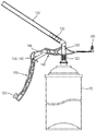
FIG. 2 shows a disposable dispensing adaptor according to an embodiment of the present invention when it is used, -
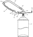
FIG. 3 shows the disposable dispensing adaptor when it is not in use, -
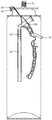
FIG. 4 shows the dispensing adaptor when it is kept before use, -
FIG. 5 is a front view of a disposable dispensing adaptor according to an exemplary arrangement, and -
FIG. 6 is a front view of a disposable dispensing adaptor according to another exemplary arrangement. - Below, embodiments of the present invention will be described in detail with reference to accompanying drawings.
- As shown in
FIG. 2 , a disposable dispensing adaptor includes an adaptormain body 100 coupled to a valve stem VS formed at a top end portion of a pressurized container PC, astem coupling portion 120 formed at one end portion of the adaptormain body 100 and coupled to and communicate with the valve stem VS, adischarging pipe 130 extended from the other end portion of the adaptormain body 100 and dispensing polyurethane, astationary lever 140 formed integrally with an outer wall of the adaptormain body 100 and extended in a direction transverse to an axial direction of the pressurized container PC, and anextended lever 150 curvedly extended from thestationary lever 140 along a lengthwise direction of the pressurized container PC in order to make the valve stem VS be inclined. -
FIG. 2 shows that the adaptormain body 100 is coupled to the valve stem VS of the pressurized container PC so as to use the disposable dispensing adaptor. As shown therein, theextended lever 150 coupled to thestationary lever 140 is curved downwardly at dispensing works. At this time, asupport projection 142 protruding from thestationary lever 140 is inserted in and coupled to aprojection accommodator 154 recessed in theextended lever 150. Thestationary lever 140 and the extendedlever 150 are relatively strongly coupled by coupling between thesupport projection 142 and theprojection accommodator 154. - During the dispensing works, a worker makes the pressurized container PC upside down so that the valve stem VS can face downward, and pulls the
extended lever 150 toward the pressurized container PC in the state that thestationary lever 140 and theextended lever 150 are strongly coupled to each other. The action of the worker is transferred to thestationary level 140 through theextended lever 150, and thus the valve stem VS is inclined with respect to the pressurized container PC. If the valve stem VS is inclined, a lower end portion of the valve stem VS is open so that liquid polyurethane pressurized by gas can come out through a hollow of the valve stem VS. The coming-out polyurethane passes through thestem coupling portion 120 coupled to and communicating with the valve stem VS, the adaptormain body 100, thedischarging pipe 130 and theoutlet pipe 132 in sequence, and is then disposed to a target portion. - The
stationary lever 140 and the extendedlever 150 are connected by afilm hinge 144 as they are molded as a single body, so that the extendedlever 150 can rotate with respect to thefilm hinge 144. Alternatively, thefilm hinge 144 may be substituted with a hinge pin or the like hinge. -
FIG. 3 shows the disposable dispensing adaptor when it is not in use. At an end portion of theextended lever 150 is provided ablocking projection 152 that can be inserted in a free end portion of theoutlet pipe 132. While the disposable dispensing adaptor is not in use, theextended lever 150 can rotate toward theoutlet pipe 132 with respect to thefilm hinge 144. In this state, theoutlet pipe 132 is bent so that the blocking projection can be fitted to the end portion of theoutlet pipe 132, thereby blocking up theoutlet pipe 132. Therefore, external air is prevented from flowing into theoutlet pipe 132, and the residual polyurethane in theoutlet pipe 132 is thus prevented from contacting air. Consequently, the polyurethane remaining in theoutlet pipe 132 is not hardened even while the dispensing work is suspended. The formation and size of theblocking projection 152 are determined in consideration of the inner diameter and material of theoutlet pipe 132 so that insertion of theoutlet pipe 132 and blocking-off of air can be properly performed. - The adaptor
main body 100 includes apeg 160 formed integrally with and extended from the outer wall of the adaptormain body 100 so that the adaptormain body 100 can be detachably mounted to astandby mounting portion 161. As shown inFIG. 4 , the adaptormain body 100 is mounted to the pressurized container PC by thepeg 160 so as to be easily kept or carried together with the pressurized container PC. Alternatively, thepeg 160 may be formed in thestationary lever 140. -
FIG. 5 shows an exemplary arrangement, in which an extended lever 150' is separated from thestationary lever 140 and coupled to thestationary lever 140 as necessary. As shown therein, an end portion of thestationary lever 140 has aninsertion hole 146 to receive an end portion of the detachable extended lever 150'. Therefore, the detachable extended lever 150' is separated from theinsertion hole 146 when the pressurized container PC is packaged, carried or kept, and is inserted in and coupled to theinsertion hole 146 at the dispensing works. Further, the detachable extended lever 150' may be manufactured to have a tubular shape by taking reduction of manufacturing costs, easiness of detachability, a feeling of grip, etc. into account. -
FIG. 6 shows another exemplary arrangement of a detachableextended lever 150". The extendedlever 150" ofFIG. 6 is manufactured to have a tubular shape, and detachably coupled to thestationary lever 140 as a coupling projection 146' provided in thestationary lever 140 is inserted in theextended lever 150". - According to the present invention, the extended
lever stationary lever 140 allows a worker to hold the pressurized container PC and the extendedlever blocking projection 152 of theextended lever
Claims (6)
- A dispensing adaptor for one-component polyurethane foam, arranged to be coupled to a valve stem (VS) of a polyurethane pressurized container (PC), the dispensing adaptor comprising:a tubular main adaptor body (100);a stem coupling portion (120) formed at one end portion of the adaptor main body (100) and arranged to be coupled to, and communicate with, the valve stem (VS);a discharging pipe (130) extending from the other end portion of the adaptor main body (100);a stationary lever (140) formed integrally with and extending from an outer wall of the adaptor main body (100); andan extended lever (150) which, in use, extends from the stationary lever (140) along a lengthwise direction of the pressurized container (PC),characterised in that the stationary lever (140) comprises a support projection (142),the extended lever (150) comprises an accommodating groove (154),the stationary lever (140) is pivotally coupled to the extended lever (150) by a hinge (144), andthe support projection (142) of the stationary lever (140) is inserted in and coupled to the accommodating groove (154) of the extended lever (150) for the dispensing operation, while allowing the support projection (142) to be disengaged from the accommodating groove (154) if the extended lever (150) is pivotally moved by a user about the hinge in a direction towards the discharging pipe (130).
- The dispensing adaptor for one-component polyurethane foam according to claim 1, wherein the extended lever (150) is detachably coupled to the stationary lever (140).
- The dispensing adaptor for one-component polyurethane foam according to claim 2, wherein the extended lever (150) has a tubular shape.
- The dispensing adaptor for one-component polyurethane foam according to claim 2, wherein one of the adaptor main body (100) and the stationary lever (140) comprises a peg (160) for coupling the dispensing adaptor to the pressurized container (PC)
- The dispensing adaptor for one-component polyurethane foam according to claim 1, wherein the hinge comprises a film hinge (144).
- The dispensing adaptor for one-component polyurethane foam according to any one of claims 1 to 5, wherein the extended lever (150) comprises a blocking projection (152) that can be inserted in a free end portion of an outlet pipe (132) detachably coupled to the discharging pipe (130).
Applications Claiming Priority (2)
| Application Number | Priority Date | Filing Date | Title |
|---|---|---|---|
| KR20130030201A KR101429615B1 (en) | 2013-03-21 | 2013-03-21 | Dispensing adapter for one component polyurethane foam |
| PCT/KR2013/007378 WO2014148702A1 (en) | 2013-03-21 | 2013-08-16 | Dispensing adaptor for one-component polyurethane foam |
Publications (3)
| Publication Number | Publication Date |
|---|---|
| EP2977333A1 EP2977333A1 (en) | 2016-01-27 |
| EP2977333A4 EP2977333A4 (en) | 2016-12-07 |
| EP2977333B1 true EP2977333B1 (en) | 2020-09-30 |
Family
ID=51580345
Family Applications (1)
| Application Number | Title | Priority Date | Filing Date |
|---|---|---|---|
| EP13878923.5A Active EP2977333B1 (en) | 2013-03-21 | 2013-08-16 | Dispensing adaptor for one-component polyurethane foam |
Country Status (19)
| Country | Link |
|---|---|
| US (1) | US9650201B2 (en) |
| EP (1) | EP2977333B1 (en) |
| KR (1) | KR101429615B1 (en) |
| CN (1) | CN105143066B (en) |
| AU (1) | AU2013383509B2 (en) |
| BR (1) | BR112015024252B1 (en) |
| CA (1) | CA2907650C (en) |
| CL (1) | CL2015002805A1 (en) |
| DK (1) | DK2977333T3 (en) |
| ES (1) | ES2839074T3 (en) |
| HU (1) | HUE053203T2 (en) |
| LT (1) | LT2977333T (en) |
| MX (1) | MX364520B (en) |
| PT (1) | PT2977333T (en) |
| RU (1) | RU2632291C2 (en) |
| SA (1) | SA515361216B1 (en) |
| UA (1) | UA117242C2 (en) |
| WO (1) | WO2014148702A1 (en) |
| ZA (1) | ZA201507807B (en) |
Cited By (3)
| Publication number | Priority date | Publication date | Assignee | Title |
|---|---|---|---|---|
| EP4768403A1 (en) | 2024-12-27 | 2026-07-01 | Selena Industrial Technologies Sp. z o.o. | APPLICATOR FOR A PRESSURE CONTAINER WITH A COMPOSITION FOR FORMING SEALANT PASTE, POLYURETHANE FOAM OR ADHESIVE |
| EP4768402A1 (en) | 2024-12-27 | 2026-07-01 | Selena Industrial Technologies Sp. z o.o. | APPLICATOR FOR A PRESSURE CONTAINER WITH A COMPOSITION FOR FORMING SEALANT PASTE, POLYURETHANE FOAM OR ADHESIVE |
| WO2026139644A1 (en) | 2024-12-27 | 2026-07-02 | Selena Industrial Technologies Sp. Z O.O. | Applicator for a pressure container comprising a composition for forming a sealing paste, polyurethane foam or adhesive |
Families Citing this family (6)
| Publication number | Priority date | Publication date | Assignee | Title |
|---|---|---|---|---|
| US10464735B2 (en) * | 2015-10-27 | 2019-11-05 | Dow Global Technologies Llc | Cap with nested handle for spray can |
| CZ201691A3 (en) * | 2016-02-19 | 2017-04-05 | Jaroslav Misler | Gun nozzle for applying polyurethane foam through a flexible nozzle and gun with such a nozzle |
| BR112019006668A2 (en) | 2016-10-20 | 2019-06-25 | Dow Global Technologies Llc | article |
| CZ307310B6 (en) * | 2017-03-24 | 2018-05-23 | IN-INN s.r.o. | A gun nozzle for attaching a flexible extension for application of polyurethane foam to hardly accessible areas and a gun with this nozzle |
| US11065635B2 (en) * | 2018-10-04 | 2021-07-20 | Flocon, Inc. | Container appendage |
| JP7146598B2 (en) | 2018-11-28 | 2022-10-04 | 株式会社吉野工業所 | Trigger type ejection container |
Family Cites Families (22)
| Publication number | Priority date | Publication date | Assignee | Title |
|---|---|---|---|---|
| US2911159A (en) * | 1956-02-29 | 1959-11-03 | Henry L Wingo | Aerosol can spray head |
| US3089625A (en) * | 1961-10-31 | 1963-05-14 | Schering Corp | Flow channeling device and valve actuating means for pressurized container |
| US4044922A (en) * | 1976-05-25 | 1977-08-30 | Bordelon Lewis O | Protective device |
| JPS54181599U (en) * | 1978-06-09 | 1979-12-22 | ||
| DE4443287C2 (en) * | 1994-12-06 | 2001-08-09 | Amv Autom Montage Vertrieb Fa | Valve assembly for a container for dispensing pressurized liquid or foam |
| DE29515276U1 (en) * | 1995-09-23 | 1997-02-06 | Fischerwerke Artur Fischer Gmbh & Co Kg, 72178 Waldachtal | Ejection device for a polyurethane foam or the like. containing can |
| US6494349B1 (en) * | 1999-11-17 | 2002-12-17 | The Gillette Company | Hand-held product dispensers having pressurized delivery |
| US6325256B1 (en) * | 2001-01-12 | 2001-12-04 | The Glidden Company | Aerosol container for flowable adhesives with adapters to avoid clogging of the aerosol container |
| EP1401734A1 (en) | 2001-06-04 | 2004-03-31 | de Schrijver, Aster | Improvements to a device delivering foams, in particular a polyurethane foam |
| DE10252161A1 (en) * | 2002-11-09 | 2004-05-27 | Thomas Gmbh | Pressurized dispenser for frozen materials is fitted with valve and sealing ring which fits into seating when valve is closed and is pushed upwards by internal pressure when valve is opened |
| US20050045664A1 (en) * | 2003-08-26 | 2005-03-03 | Taylor Thomas A. | Actuation assistance apparatus and method |
| DE102004012470B4 (en) * | 2003-09-01 | 2016-10-20 | Rpm Ireland Ip Ltd. | Operating handle for a Ortschaumdose, as well as combination of a Ortschaumdose with an operating handle |
| US7377408B2 (en) * | 2003-09-19 | 2008-05-27 | Rieke Corporation | Fluid dispenser |
| DE102004003264A1 (en) * | 2004-01-21 | 2005-08-18 | Fazekas, Gàbor | Adapter for aerosol cans |
| CN2755036Y (en) * | 2004-11-23 | 2006-02-01 | 梁配辉 | One-piece cover with handle |
| UA88451C2 (en) | 2006-03-20 | 2009-10-26 | Павел Анатольевич Еремеев | Actuator of outlet valve of sealed container with fluid under pressure and method of preparation for operation of cylindrical container with fluid under pressure equipped with outlet valve |
| KR100778239B1 (en) * | 2006-08-11 | 2007-11-29 | 이동광 | Auxiliary Gun for Spraying Polyurethane Foam |
| CN101730652B (en) * | 2007-07-05 | 2012-05-23 | 艾尔塔彻姆控股公司 | Aerosol valve |
| FR2923810A1 (en) * | 2007-11-15 | 2009-05-22 | Oreal | DISPENSING HEAD OF THE TYPE A TRIGGER TRIGGER. |
| JP5186985B2 (en) * | 2008-04-10 | 2013-04-24 | アース製薬株式会社 | Method for blocking harmful animal entry holes using aerosol spray device |
| DE102009018528B4 (en) * | 2009-04-24 | 2017-10-26 | Henkel Ag & Co. Kgaa | Dispenser for dispensing a material from a container |
| EE01065U1 (en) * | 2010-05-19 | 2012-01-16 | As Enko | A pen applicator mounted on a cylinder head with a balloon applicator adapter |
-
2013
- 2013-03-21 KR KR20130030201A patent/KR101429615B1/en active Active
- 2013-08-16 LT LTEP13878923.5T patent/LT2977333T/en unknown
- 2013-08-16 RU RU2015145163A patent/RU2632291C2/en active
- 2013-08-16 CA CA2907650A patent/CA2907650C/en active Active
- 2013-08-16 EP EP13878923.5A patent/EP2977333B1/en active Active
- 2013-08-16 UA UAA201510253A patent/UA117242C2/en unknown
- 2013-08-16 CN CN201380074884.9A patent/CN105143066B/en active Active
- 2013-08-16 PT PT138789235T patent/PT2977333T/en unknown
- 2013-08-16 BR BR112015024252-9A patent/BR112015024252B1/en not_active IP Right Cessation
- 2013-08-16 DK DK13878923.5T patent/DK2977333T3/en active
- 2013-08-16 AU AU2013383509A patent/AU2013383509B2/en not_active Ceased
- 2013-08-16 MX MX2015013309A patent/MX364520B/en active IP Right Grant
- 2013-08-16 ES ES13878923T patent/ES2839074T3/en active Active
- 2013-08-16 HU HUE13878923A patent/HUE053203T2/en unknown
- 2013-08-16 WO PCT/KR2013/007378 patent/WO2014148702A1/en not_active Ceased
-
2015
- 2015-09-17 CL CL2015002805A patent/CL2015002805A1/en unknown
- 2015-09-18 US US14/858,067 patent/US9650201B2/en active Active
- 2015-09-20 SA SA515361216A patent/SA515361216B1/en unknown
- 2015-10-20 ZA ZA2015/07807A patent/ZA201507807B/en unknown
Non-Patent Citations (1)
| Title |
|---|
| None * |
Cited By (5)
| Publication number | Priority date | Publication date | Assignee | Title |
|---|---|---|---|---|
| EP4768403A1 (en) | 2024-12-27 | 2026-07-01 | Selena Industrial Technologies Sp. z o.o. | APPLICATOR FOR A PRESSURE CONTAINER WITH A COMPOSITION FOR FORMING SEALANT PASTE, POLYURETHANE FOAM OR ADHESIVE |
| EP4768402A1 (en) | 2024-12-27 | 2026-07-01 | Selena Industrial Technologies Sp. z o.o. | APPLICATOR FOR A PRESSURE CONTAINER WITH A COMPOSITION FOR FORMING SEALANT PASTE, POLYURETHANE FOAM OR ADHESIVE |
| WO2026139644A1 (en) | 2024-12-27 | 2026-07-02 | Selena Industrial Technologies Sp. Z O.O. | Applicator for a pressure container comprising a composition for forming a sealing paste, polyurethane foam or adhesive |
| WO2026139171A1 (en) | 2024-12-27 | 2026-07-02 | Selena Industrial Technologies Sp. Z O.O. | Applicator for a pressure container containing a composition for forming sealing paste, polyurethane foam or adhesive |
| WO2026139170A1 (en) | 2024-12-27 | 2026-07-02 | Selena Industrial Technologies Sp. Z O.O. | Applicator for a pressure container containing a composition for forming sealing paste, polyurethane foam or adhesive |
Also Published As
| Publication number | Publication date |
|---|---|
| US20160001962A1 (en) | 2016-01-07 |
| LT2977333T (en) | 2021-01-11 |
| CN105143066A (en) | 2015-12-09 |
| DK2977333T3 (en) | 2021-01-11 |
| CN105143066B (en) | 2017-06-16 |
| RU2015145163A (en) | 2017-04-26 |
| CA2907650A1 (en) | 2014-09-25 |
| US9650201B2 (en) | 2017-05-16 |
| CA2907650C (en) | 2020-03-24 |
| EP2977333A1 (en) | 2016-01-27 |
| RU2632291C2 (en) | 2017-10-03 |
| AU2013383509A1 (en) | 2015-11-12 |
| EP2977333A4 (en) | 2016-12-07 |
| ES2839074T3 (en) | 2021-07-05 |
| AU2013383509B2 (en) | 2017-08-03 |
| PT2977333T (en) | 2021-01-04 |
| UA117242C2 (en) | 2018-07-10 |
| HUE053203T2 (en) | 2021-06-28 |
| MX364520B (en) | 2019-04-30 |
| CL2015002805A1 (en) | 2016-05-27 |
| KR101429615B1 (en) | 2014-08-13 |
| MX2015013309A (en) | 2016-06-07 |
| BR112015024252B1 (en) | 2020-12-29 |
| BR112015024252A2 (en) | 2017-07-18 |
| ZA201507807B (en) | 2019-12-18 |
| SA515361216B1 (en) | 2019-05-05 |
| WO2014148702A1 (en) | 2014-09-25 |
Similar Documents
| Publication | Publication Date | Title |
|---|---|---|
| CA2907650C (en) | Dispensing adaptor for one-component polyurethane foam | |
| EP3023239B1 (en) | Emergency repair kit for punctured tires | |
| EP2815875B1 (en) | Vehicle-mounted air compressor device | |
| US9579686B2 (en) | Fluid dispensing assemblies and methods of dispensing fluids from containers | |
| CA2602217C (en) | A multicomponent cartridge | |
| TWM535067U (en) | Cleaning appliance | |
| US20140224828A1 (en) | Tip seal having a position indicator, the tip seal being configured to dispense a foam solution | |
| WO2006081081A3 (en) | Personal hydration system | |
| US8657141B2 (en) | Cartridge with integrated closure cap | |
| EP2743002B1 (en) | Tip seal for an adapter for a pressurized dispensing container comprising a viscous foamable solution and adapter provided with such a tip seal | |
| JP2010265037A (en) | Valve system assembly | |
| US20120048421A1 (en) | Refill cap cartridge | |
| JP6144601B2 (en) | Dispensing adapter for one-component polyurethane foam pressure vessels | |
| KR101788937B1 (en) | Fixed quantity delivering apparatus for liquid container | |
| KR200491282Y1 (en) | water extinguisher for fire drill | |
| CN211705730U (en) | Fire extinguishing device for training | |
| JPH11276614A (en) | Fire extinguisher | |
| JP5467991B2 (en) | Liquid ejection container | |
| JP2015524324A (en) | Pneumatically operable surgical instrument | |
| KR100920270B1 (en) | Filling Gas Container | |
| KR200157188Y1 (en) | Gas sprayer | |
| KR101015950B1 (en) | Fire extinguisher with replaceable extinguishing agent container | |
| JP2009506304A (en) | Liquid handling equipment | |
| HK1180564A (en) | Kit comprising a liquid container and a refill device | |
| KR20110046251A (en) | Container with shock absorbing element |
Legal Events
| Date | Code | Title | Description |
|---|---|---|---|
| PUAI | Public reference made under article 153(3) epc to a published international application that has entered the european phase |
Free format text: ORIGINAL CODE: 0009012 |
|
| 17P | Request for examination filed |
Effective date: 20150918 |
|
| AK | Designated contracting states |
Kind code of ref document: A1 Designated state(s): AL AT BE BG CH CY CZ DE DK EE ES FI FR GB GR HR HU IE IS IT LI LT LU LV MC MK MT NL NO PL PT RO RS SE SI SK SM TR |
|
| AX | Request for extension of the european patent |
Extension state: BA ME |
|
| DAX | Request for extension of the european patent (deleted) | ||
| A4 | Supplementary search report drawn up and despatched |
Effective date: 20161104 |
|
| RIC1 | Information provided on ipc code assigned before grant |
Ipc: B65D 83/14 20060101AFI20161028BHEP Ipc: B65D 83/30 20060101ALI20161028BHEP Ipc: B65D 83/16 20060101ALI20161028BHEP Ipc: B65D 83/20 20060101ALI20161028BHEP Ipc: B65D 83/28 20060101ALI20161028BHEP |
|
| STAA | Information on the status of an ep patent application or granted ep patent |
Free format text: STATUS: EXAMINATION IS IN PROGRESS |
|
| 17Q | First examination report despatched |
Effective date: 20190521 |
|
| REG | Reference to a national code |
Ref country code: DE Ref legal event code: R079 Ref document number: 602013073004 Country of ref document: DE Free format text: PREVIOUS MAIN CLASS: B65D0083160000 Ipc: B65D0083200000 |
|
| GRAP | Despatch of communication of intention to grant a patent |
Free format text: ORIGINAL CODE: EPIDOSNIGR1 |
|
| STAA | Information on the status of an ep patent application or granted ep patent |
Free format text: STATUS: GRANT OF PATENT IS INTENDED |
|
| INTG | Intention to grant announced |
Effective date: 20200526 |
|
| RIC1 | Information provided on ipc code assigned before grant |
Ipc: B65D 83/34 20060101ALN20200512BHEP Ipc: B65D 83/20 20060101AFI20200512BHEP Ipc: B65D 83/30 20060101ALI20200512BHEP |
|
| GRAS | Grant fee paid |
Free format text: ORIGINAL CODE: EPIDOSNIGR3 |
|
| GRAA | (expected) grant |
Free format text: ORIGINAL CODE: 0009210 |
|
| STAA | Information on the status of an ep patent application or granted ep patent |
Free format text: STATUS: THE PATENT HAS BEEN GRANTED |
|
| AK | Designated contracting states |
Kind code of ref document: B1 Designated state(s): AL AT BE BG CH CY CZ DE DK EE ES FI FR GB GR HR HU IE IS IT LI LT LU LV MC MK MT NL NO PL PT RO RS SE SI SK SM TR |
|
| REG | Reference to a national code |
Ref country code: GB Ref legal event code: FG4D Ref country code: CH Ref legal event code: EP |
|
| REG | Reference to a national code |
Ref country code: AT Ref legal event code: REF Ref document number: 1318570 Country of ref document: AT Kind code of ref document: T Effective date: 20201015 Ref country code: DE Ref legal event code: R096 Ref document number: 602013073004 Country of ref document: DE |
|
| REG | Reference to a national code |
Ref country code: IE Ref legal event code: FG4D |
|
| REG | Reference to a national code |
Ref country code: RO Ref legal event code: EPE |
|
| REG | Reference to a national code |
Ref country code: FI Ref legal event code: FGE |
|
| REG | Reference to a national code |
Ref country code: PT Ref legal event code: SC4A Ref document number: 2977333 Country of ref document: PT Date of ref document: 20210104 Kind code of ref document: T Free format text: AVAILABILITY OF NATIONAL TRANSLATION Effective date: 20201223 |
|
| REG | Reference to a national code |
Ref country code: DK Ref legal event code: T3 Effective date: 20210106 |
|
| REG | Reference to a national code |
Ref country code: NL Ref legal event code: FP |
|
| REG | Reference to a national code |
Ref country code: SE Ref legal event code: TRGR |
|
| PG25 | Lapsed in a contracting state [announced via postgrant information from national office to epo] |
Ref country code: GR Free format text: LAPSE BECAUSE OF FAILURE TO SUBMIT A TRANSLATION OF THE DESCRIPTION OR TO PAY THE FEE WITHIN THE PRESCRIBED TIME-LIMIT Effective date: 20201231 Ref country code: HR Free format text: LAPSE BECAUSE OF FAILURE TO SUBMIT A TRANSLATION OF THE DESCRIPTION OR TO PAY THE FEE WITHIN THE PRESCRIBED TIME-LIMIT Effective date: 20200930 |
|
| REG | Reference to a national code |
Ref country code: SK Ref legal event code: T3 Ref document number: E 36096 Country of ref document: SK |
|
| REG | Reference to a national code |
Ref country code: CH Ref legal event code: NV Representative=s name: TR-IP CONSULTING LLC, CH Ref country code: EE Ref legal event code: FG4A Ref document number: E020157 Country of ref document: EE Effective date: 20201229 |
|
| PG25 | Lapsed in a contracting state [announced via postgrant information from national office to epo] |
Ref country code: RS Free format text: LAPSE BECAUSE OF FAILURE TO SUBMIT A TRANSLATION OF THE DESCRIPTION OR TO PAY THE FEE WITHIN THE PRESCRIBED TIME-LIMIT Effective date: 20200930 |
|
| REG | Reference to a national code |
Ref country code: NO Ref legal event code: T2 Effective date: 20200930 |
|
| PG25 | Lapsed in a contracting state [announced via postgrant information from national office to epo] |
Ref country code: SM Free format text: LAPSE BECAUSE OF FAILURE TO SUBMIT A TRANSLATION OF THE DESCRIPTION OR TO PAY THE FEE WITHIN THE PRESCRIBED TIME-LIMIT Effective date: 20200930 |
|
| PG25 | Lapsed in a contracting state [announced via postgrant information from national office to epo] |
Ref country code: AL Free format text: LAPSE BECAUSE OF FAILURE TO SUBMIT A TRANSLATION OF THE DESCRIPTION OR TO PAY THE FEE WITHIN THE PRESCRIBED TIME-LIMIT Effective date: 20200930 Ref country code: IS Free format text: LAPSE BECAUSE OF FAILURE TO SUBMIT A TRANSLATION OF THE DESCRIPTION OR TO PAY THE FEE WITHIN THE PRESCRIBED TIME-LIMIT Effective date: 20210130 |
|
| REG | Reference to a national code |
Ref country code: HU Ref legal event code: AG4A Ref document number: E053203 Country of ref document: HU |
|
| REG | Reference to a national code |
Ref country code: DE Ref legal event code: R097 Ref document number: 602013073004 Country of ref document: DE |
|
| REG | Reference to a national code |
Ref country code: ES Ref legal event code: FG2A Ref document number: 2839074 Country of ref document: ES Kind code of ref document: T3 Effective date: 20210705 |
|
| PLBE | No opposition filed within time limit |
Free format text: ORIGINAL CODE: 0009261 |
|
| STAA | Information on the status of an ep patent application or granted ep patent |
Free format text: STATUS: NO OPPOSITION FILED WITHIN TIME LIMIT |
|
| 26N | No opposition filed |
Effective date: 20210701 |
|
| PG25 | Lapsed in a contracting state [announced via postgrant information from national office to epo] |
Ref country code: SI Free format text: LAPSE BECAUSE OF FAILURE TO SUBMIT A TRANSLATION OF THE DESCRIPTION OR TO PAY THE FEE WITHIN THE PRESCRIBED TIME-LIMIT Effective date: 20200930 |
|
| PG25 | Lapsed in a contracting state [announced via postgrant information from national office to epo] |
Ref country code: MC Free format text: LAPSE BECAUSE OF FAILURE TO SUBMIT A TRANSLATION OF THE DESCRIPTION OR TO PAY THE FEE WITHIN THE PRESCRIBED TIME-LIMIT Effective date: 20200930 |
|
| GBPC | Gb: european patent ceased through non-payment of renewal fee |
Effective date: 20210816 |
|
| PG25 | Lapsed in a contracting state [announced via postgrant information from national office to epo] |
Ref country code: IS Free format text: LAPSE BECAUSE OF FAILURE TO SUBMIT A TRANSLATION OF THE DESCRIPTION OR TO PAY THE FEE WITHIN THE PRESCRIBED TIME-LIMIT Effective date: 20210130 Ref country code: LU Free format text: LAPSE BECAUSE OF NON-PAYMENT OF DUE FEES Effective date: 20210816 |
|
| PG25 | Lapsed in a contracting state [announced via postgrant information from national office to epo] |
Ref country code: IE Free format text: LAPSE BECAUSE OF NON-PAYMENT OF DUE FEES Effective date: 20210816 Ref country code: GB Free format text: LAPSE BECAUSE OF NON-PAYMENT OF DUE FEES Effective date: 20210816 |
|
| REG | Reference to a national code |
Ref country code: AT Ref legal event code: UEP Ref document number: 1318570 Country of ref document: AT Kind code of ref document: T Effective date: 20200930 |
|
| PG25 | Lapsed in a contracting state [announced via postgrant information from national office to epo] |
Ref country code: CY Free format text: LAPSE BECAUSE OF FAILURE TO SUBMIT A TRANSLATION OF THE DESCRIPTION OR TO PAY THE FEE WITHIN THE PRESCRIBED TIME-LIMIT Effective date: 20200930 |
|
| PG25 | Lapsed in a contracting state [announced via postgrant information from national office to epo] |
Ref country code: MK Free format text: LAPSE BECAUSE OF FAILURE TO SUBMIT A TRANSLATION OF THE DESCRIPTION OR TO PAY THE FEE WITHIN THE PRESCRIBED TIME-LIMIT Effective date: 20200930 |
|
| PGFP | Annual fee paid to national office [announced via postgrant information from national office to epo] |
Ref country code: NL Payment date: 20240821 Year of fee payment: 12 |
|
| PG25 | Lapsed in a contracting state [announced via postgrant information from national office to epo] |
Ref country code: MT Free format text: LAPSE BECAUSE OF FAILURE TO SUBMIT A TRANSLATION OF THE DESCRIPTION OR TO PAY THE FEE WITHIN THE PRESCRIBED TIME-LIMIT Effective date: 20200930 |
|
| PGFP | Annual fee paid to national office [announced via postgrant information from national office to epo] |
Ref country code: LT Payment date: 20240812 Year of fee payment: 12 |
|
| PGFP | Annual fee paid to national office [announced via postgrant information from national office to epo] |
Ref country code: DK Payment date: 20240829 Year of fee payment: 12 |
|
| PGFP | Annual fee paid to national office [announced via postgrant information from national office to epo] |
Ref country code: BE Payment date: 20240821 Year of fee payment: 12 |
|
| PGFP | Annual fee paid to national office [announced via postgrant information from national office to epo] |
Ref country code: CH Payment date: 20240901 Year of fee payment: 12 |
|
| PGFP | Annual fee paid to national office [announced via postgrant information from national office to epo] |
Ref country code: AT Payment date: 20240822 Year of fee payment: 12 |
|
| PGFP | Annual fee paid to national office [announced via postgrant information from national office to epo] |
Ref country code: LV Payment date: 20240819 Year of fee payment: 12 |
|
| PGFP | Annual fee paid to national office [announced via postgrant information from national office to epo] |
Ref country code: NO Payment date: 20240829 Year of fee payment: 12 Ref country code: SE Payment date: 20240821 Year of fee payment: 12 |
|
| PGFP | Annual fee paid to national office [announced via postgrant information from national office to epo] |
Ref country code: HU Payment date: 20250825 Year of fee payment: 13 |
|
| PGFP | Annual fee paid to national office [announced via postgrant information from national office to epo] |
Ref country code: FI Payment date: 20250822 Year of fee payment: 13 Ref country code: ES Payment date: 20250926 Year of fee payment: 13 Ref country code: PT Payment date: 20250807 Year of fee payment: 13 |
|
| PGFP | Annual fee paid to national office [announced via postgrant information from national office to epo] |
Ref country code: DE Payment date: 20250820 Year of fee payment: 13 |
|
| PGFP | Annual fee paid to national office [announced via postgrant information from national office to epo] |
Ref country code: TR Payment date: 20250811 Year of fee payment: 13 Ref country code: PL Payment date: 20250812 Year of fee payment: 13 Ref country code: IT Payment date: 20250820 Year of fee payment: 13 |
|
| PGFP | Annual fee paid to national office [announced via postgrant information from national office to epo] |
Ref country code: BG Payment date: 20250822 Year of fee payment: 13 |
|
| PGFP | Annual fee paid to national office [announced via postgrant information from national office to epo] |
Ref country code: FR Payment date: 20250829 Year of fee payment: 13 |
|
| PGFP | Annual fee paid to national office [announced via postgrant information from national office to epo] |
Ref country code: EE Payment date: 20250908 Year of fee payment: 13 Ref country code: CZ Payment date: 20250807 Year of fee payment: 13 |
|
| PGFP | Annual fee paid to national office [announced via postgrant information from national office to epo] |
Ref country code: RO Payment date: 20250813 Year of fee payment: 13 |
|
| PGFP | Annual fee paid to national office [announced via postgrant information from national office to epo] |
Ref country code: SK Payment date: 20250813 Year of fee payment: 13 |
|
| REG | Reference to a national code |
Ref country code: LT Ref legal event code: MM4D Effective date: 20250816 |
|
| REG | Reference to a national code |
Ref country code: DK Ref legal event code: EBP Effective date: 20250831 |
|
| REG | Reference to a national code |
Ref country code: CH Ref legal event code: H13 Free format text: ST27 STATUS EVENT CODE: U-0-0-H10-H13 (AS PROVIDED BY THE NATIONAL OFFICE) Effective date: 20260324 |
|
| REG | Reference to a national code |
Ref country code: NL Ref legal event code: MM Effective date: 20250901 |
|
| PG25 | Lapsed in a contracting state [announced via postgrant information from national office to epo] |
Ref country code: LT Free format text: LAPSE BECAUSE OF NON-PAYMENT OF DUE FEES Effective date: 20250816 |
|
| PG25 | Lapsed in a contracting state [announced via postgrant information from national office to epo] |
Ref country code: NO Free format text: LAPSE BECAUSE OF NON-PAYMENT OF DUE FEES Effective date: 20250831 |
|
| PG25 | Lapsed in a contracting state [announced via postgrant information from national office to epo] |
Ref country code: AT Free format text: LAPSE BECAUSE OF NON-PAYMENT OF DUE FEES Effective date: 20250816 |
|
| REG | Reference to a national code |
Ref country code: AT Ref legal event code: MM01 Ref document number: 1318570 Country of ref document: AT Kind code of ref document: T Effective date: 20250816 |
|
| PG25 | Lapsed in a contracting state [announced via postgrant information from national office to epo] |
Ref country code: CH Free format text: LAPSE BECAUSE OF NON-PAYMENT OF DUE FEES Effective date: 20250831 |
|
| PG25 | Lapsed in a contracting state [announced via postgrant information from national office to epo] |
Ref country code: LV Free format text: LAPSE BECAUSE OF NON-PAYMENT OF DUE FEES Effective date: 20250816 |
|
| REG | Reference to a national code |
Ref country code: BE Ref legal event code: MM Effective date: 20250831 |
|
| PG25 | Lapsed in a contracting state [announced via postgrant information from national office to epo] |
Ref country code: NL Free format text: LAPSE BECAUSE OF NON-PAYMENT OF DUE FEES Effective date: 20250901 |
|
| PG25 | Lapsed in a contracting state [announced via postgrant information from national office to epo] |
Ref country code: DK Free format text: LAPSE BECAUSE OF NON-PAYMENT OF DUE FEES Effective date: 20250831 |
|
| PG25 | Lapsed in a contracting state [announced via postgrant information from national office to epo] |
Ref country code: BE Free format text: LAPSE BECAUSE OF NON-PAYMENT OF DUE FEES Effective date: 20250831 |
|
| PG25 | Lapsed in a contracting state [announced via postgrant information from national office to epo] |
Ref country code: SE Free format text: LAPSE BECAUSE OF NON-PAYMENT OF DUE FEES Effective date: 20250817 |