EP2977235A1 - Tire dismounting hook apparatus and tire dismounting device - Google Patents
Tire dismounting hook apparatus and tire dismounting device Download PDFInfo
- Publication number
- EP2977235A1 EP2977235A1 EP14184384.7A EP14184384A EP2977235A1 EP 2977235 A1 EP2977235 A1 EP 2977235A1 EP 14184384 A EP14184384 A EP 14184384A EP 2977235 A1 EP2977235 A1 EP 2977235A1
- Authority
- EP
- European Patent Office
- Prior art keywords
- tire dismounting
- stand
- cylinder
- piston rod
- curved lever
- Prior art date
- Legal status (The legal status is an assumption and is not a legal conclusion. Google has not performed a legal analysis and makes no representation as to the accuracy of the status listed.)
- Granted
Links
Images

Classifications
-
- B—PERFORMING OPERATIONS; TRANSPORTING
- B60—VEHICLES IN GENERAL
- B60C—VEHICLE TYRES; TYRE INFLATION; TYRE CHANGING; CONNECTING VALVES TO INFLATABLE ELASTIC BODIES IN GENERAL; DEVICES OR ARRANGEMENTS RELATED TO TYRES
- B60C25/00—Apparatus or tools adapted for mounting, removing or inspecting tyres
- B60C25/01—Apparatus or tools adapted for mounting, removing or inspecting tyres for removing tyres from or mounting tyres on wheels
- B60C25/05—Machines
- B60C25/0563—Tools interacting with the tyre and moved in relation to the tyre during operation
- B60C25/0578—Tools interacting with the tyre and moved in relation to the tyre during operation hooking only
Definitions
- the present invention relates to the field of designing a tire dismounting device, in particular to a tire dismounting hook apparatus and a tire dismounting device.
- a pneumatic tire dismounting hook according to a conventional art has a simple structure, and provides a practicability and credibility, but has the following shortcomings.
- an embodiment of the present invention provides a tire dismounting hook, which is applied to a tire dismounting device and includes a cylinder and a tube assembly connected with the cylinder.
- the tire dismounting hook apparatus further includes a stand, a curved lever, a linkage mechanism, and a tire dismounting hook.
- the stand is connected with one end of the cylinder, which is positioned close to a piston rod of the cylinder.
- the curved lever is disposed in the stand and is hinged with the piston rod.
- An arc groove having a predetermined width being disposed on the curved lever, a roll wheel is disposed in the arc groove in contact with an inner wall of the arc groove, and a roll shaft corresponding to the roll wheel is disposed in the stand.
- the roll shaft penetrates through the roll wheel.
- the linkage mechanism is hinged with one end of the curved lever, which is positioned apart from the piston rod.
- One end of the linkage mechanism which is positioned apart from the curved lever, extends to an outside of the stand.
- the tire dismounting hook is hinged with the one end of the linkage mechanism, which is positioned apart from the curved lever.
- the cylinder is connected with the stand by a flange structure.
- the linkage mechanism includes a first swing arm and a second swing arm, each of which is hinged with the stand at one end and is hinged with the tire dismounting hook at the other end.
- the second swing arm is disposed under the first swing arm and is disposed farther than the first swing arm with respect to the curved lever.
- the one end of the curved lever positioned apart from the piston rod is hinged with an arm body of the first swing arm.
- the first swing arm includes a first portion and a second portion angled with each other by a predetermined angle. One end of the first portion, which is apart from the second portion, is hinged with the stand, and one end of the second portion, which is apart from the first portion, is hinged with the tire dismounting hook.
- the second swing arm is disposed parallel to the second portion.
- Two ends of the roll shaft are fixed to the stand in one horizontal direction and shield rings are disposed at a fixing position of the roll shaft to the stand.
- the curved lever is hinged with the piston rod via a piston rod joint and a spring pad is disposed at a hinge position of the curved lever and the piston rod joint.
- the tire dismounting hook apparatus further includes a tire dismounting device bird head connected with one end of the stand and disposed on a first surface of the stand.
- the one end of the stand is positioned apart from the cylinder.
- the first surface is a surface that is positioned opposite to the piston rod.
- the tire dismounting hook apparatus further includes a rim protection mat connected with the one end of the stand, which is positioned apart from the cylinder, and connected with the tire dismounting device bird head.
- the rim protection mat is disposed on a second surface of the stand.
- the second surface is a surface that is positioned opposite to the cylinder.
- the tire dismounting hook apparatus further includes a control valve assembly that controls an operation state of the cylinder.
- the control valve assembly is connected with the cylinder.
- the present invention provides a tire dismounting device includes above-described tire dismounting hook apparatus.
- the present invention provides the following advantages.
- the tire dismounting hook apparatus includes a cylinder and a tube assembly connected with the cylinder, and further includes a stand, a curved lever, a linkage mechanism, and a tire dismounting hook.
- the stand is connected with one end of the cylinder, which is positioned close to a piston rod of the cylinder.
- the curved lever is disposed in the stand and is hinged with the piston rod.
- An arc groove having a predetermined width is disposed on the curved lever, a roll wheel is disposed in the arc groove, and a roll shaft corresponding to the roll wheel is disposed in the stand.
- the roll shaft penetrates through the roll wheel.
- the linkage mechanism is connected with one end of the curved lever, which is positioned apart from the piston rod.
- the tire dismounting hook is hinged with the one end of the linkage mechanism, which is positioned apart from the curved lever and extends to an outside of the stand.
- the piston rod drives the curved lever to move in a protruding direction of the piston and the curved lever moves along the arc groove in a direction moving away from the piston rod causing a movement of the tire dismounting hook in the protruding direction of the piston and in the direction moving away from the piston rod.
- the present invention provides a flexibility of using the tire dismounting hook apparatus, reduces a size of the tire dismounting hook apparatus, improves an assembly process, avoids an interference between the stand and the tire, improves an efficiency of tire dismounting work, and extends a service life of the cylinder.
- a structure of a pneumatic tire dismounting hook apparatus is typical four-bar tire dismounting mechanism.
- the pneumatic tire dismounting hook apparatus according to the prior art has a simple structure and provides a practicability and a credibility, but has the following shortcomings.
- a lower hinge hole of a cylinder piston rod, an upper hinge hole of an upper rocker, an upper hinge hole of a hook form a common hinge joint. Since the three hinge holes are arranged in a horizontal direction, a size of the common hinge joint in the horizontal direction is increased.
- a horizontal dimension of a stand of the tire dismounting hook needs to be increased.
- a hinge joint structure makes a front portion of the cylinder being hanged when the cylinder is mounted.
- the piston rod continually swings during an expand operation and a retract operation with a position change of the common hinge joint.
- a service life of the cylinder is shortened by an inevitable unilateral wear and tear.
- the tire dismounting hook apparatus reduces a body size of the mechanism, improves an assembly technique, makes structures compact, provides stable and reliable performance, provides improved fire dismounting operation, improves an operating condition of the cylinder, and extends a service life of the cylinder.
- a tire dismounting hook apparatus As shown in Fig. 2 to Fig. 5 , a tire dismounting hook apparatus according to an embodiment of the present invention is applied to a tire dismounting device.
- the tire dismounting hook apparatus includes a cylinder 2 and a tube assembly 1 connected with the cylinder 2.
- the tire dismounting hook apparatus further includes a stand connected with one end of the cylinder 2 which is positioned close to a piston rod of the cylinder 2.
- a curved lever 17 hinged with the piston rod is provided in the stand 3.
- An arc groove having a predetermined width is disposed on the curved lever 17, a roll wheel 16 is disposed in the arc groove in contact with an inner wall of the arc groove, a roll shaft 15 corresponding to the roll wheel 16 is disposed in the stand 3, and the roll shaft 15 penetrates through the roll wheel 16.
- the piston rod drives the curved lever 17 to move in a protruding direction of the piston and the curved lever 17 moves along the arc groove in a direction moving away from the piston rod causing a movement of the tire dismounting hook 9 in the protruding direction of the piston and in the direction moving away from the piston rod.
- the piston rod drives the curved lever 17 to move in a protruding direction of the piston, and at the same time, the roll wheel 16 disposed on the curved lever 17 rolls on the roll shaft 15 causing a movement of the curved lever 17 along the arc groove in a direction moving away from the piston rod.
- the curved lever 17 drives the tire dismounting hook 9 to move in the protruding direction of the piston and in the direction moving away from the piston rod.
- the piston rod drives the curved lever 17 to move in a retracting direction of the piston.
- the roll wheel 16 disposed on the curved lever 17 rolls on the roll shaft 15, and drives the curved lever 17 to move along arc groove in a direction approaching to the piston rod.
- the curved lever 17 drives the tire dismount hook 9 to move in the retracting direction of the piston and in the direction approaching to the piston rod.
- the stand 3 is provided by a welded element. Thus, a robustness of the tire dismounting hook apparatus is secured.
- the roll wheel 16 is able to roll along the arc groove.
- a diameter of the roll wheel 16 is equal to a width of the arc groove.
- the cylinder 2 is connected with the stand 3 by a flange structure.
- the cylinder 2 may be fixed to an upper portion of the stand 3 in a flange fastening manner at its front end.
- a movement of the piston rod is pure expanding and retracting operation.
- using flange fastening manner to fix the front end provides a simple assembly, adjustment and maintenance. Further, since a working condition of the cylinder 2 is improved, the service life of the cylinder 2 is extended.
- the linkage mechanism may include a first swing arm 11 and a second swing arm 10, each of which is hinged with the stand 3 at one end and is hinged with the tire dismounting hook 9 at the other end.
- the second swing arm 10 is disposed under the first swing arm 11 and is disposed farther than the first swing arm 11 with respect to the curved lever 17.
- the one end of the curved lever 17, which is positioned apart from the piston rod, is hinged with an arm body of the first swing arm 11.
- the first swing arm 11 drives the tire dismounting hook 9 to generate a relative movement.
- the second swing arm 10 secures a stability of the tire dismounting hook 9 during the movement in order to restrict a random swing movement of the tire dismounting hook.
- the first swing arm 11 is hinged with a first hinge hole 91 of the tire dismounting hook 9, which is apart from the hook shape member 93.
- the second swing arm 10 is hinged with a second hinge hole 92 of the tire dismounting hook 9.
- the second hinge hole 92 is disposed between the first hinge hole 91 and the hook shape member 93.
- first swing arm 11 may be hinged with the stand 3 via a first long hinge shaft 131 at an inside portion of the stand 3.
- the first long hinge shaft 131 may be fixed using a fastening screw 18.
- the second swing arm 10 may be hinged with the stand 3 via a second long hinge shaft 132 at an inside portion of the stand 3.
- the second long hinge shaft 132 may be fixed using a fastening screw 18.
- the first hinge hole 91 of the tire dismounting hook 9 may be hinged with the first swing arm 11 by a first short hinge shaft 121.
- the first short hinge shaft 121 may be fixed using a fastening screw 18.
- the second hinge hole 92 of the tire dismounting hook 9 may be hinged with the second swing arm 10 by a second short hinge shaft 122.
- the second short hinge shaft 122 may be fixed using a fastening screw 18.
- the curved lever 17 may be hinged with the arm body of the first swing arm 11 by a third short hinge shaft 123.
- the third short hinge shaft 123 may be fixed using a fastening screw 18.
- the first swing arm 11 includes a first portion 111 and a second portion 112 angled with each other by a predetermined angle.
- One end of the first portion 111, which is apart from the second portion 112, is hinged with the stand 3.
- One end of the second portion 112, which is apart from the first portion 111, is hinged with the tire dismounting hook 9.
- the second swing arm 10 is disposed parallel to the second portion 112.
- two ends of the roll shaft 15 are fixed to the stand 3 in one horizontal direction, and a shield ring 14 is disposed at a fix position of the roll shaft 15 to the stand 3.
- the roll shaft is connected with the stand 3 in a two-ends supporting manner.
- a stability of the connection is secured.
- the shield ring 14 is disposed at a fix position of the roll shaft 15 to the stand 3.
- the shield ring 14 may be provided by a elastic shield ring.
- a bearing pressure at the fix position between the roll shaft 15 and the stand 3 is reduced.
- the curved lever 17 is hinged with the piston rod via a piston rod joint 21, and a spring pad 19 is disposed at a hinge position between the curved lever 17 and the piston rod joint 21.
- the apparatus provides a simple mounting and dismounting, provides an easy replacement and adjustment, and improves an usefulness. Since the spring pad 19 is disposed at the hinge position between the curved lever 17 and the piston rod joint 21, an improved cushioning effect is provided and a stability of the apparatus is improved.
- the curved lever 17 may be hinged with the piston rod joint 21 via a drive shaft 20 .
- the piston rod joint 21 may be connected with the piston rod via a hexagonal slim nut 22. This configuration secures a mounting stability, simplifies a dismounting work, and provides easy adjustment.
- the tire dismounting hook apparatus may further include a tire dismounting device bird head 5.
- the tire dismounting device bird head 5 is connected with one end of the stand 3, which is positioned apart from the cylinder 2.
- the tire dismounting device bird head 5 is also disposed on a first surface of the stand 3, which is positioned opposite to the piston rod.
- the tire dismounting device bird head 5 improves an operation precision of the apparatus with respect to the tire, and enables a smooth and speedy tire dismounting work.
- the tire dismounting device bird head 5 is disposed on the surface of the stand 3, which is opposite to the piston rod.
- an operation of the tire dismounting hook 9 is not adversely affected by the dismounting device bird head 5, achieves a proper arrangement of the components, and a stable operation of the apparatus.
- the tire dismounting hook apparatus may further include a rim protection mat 6 connected with the one end of the stand 3, which is positioned apart from the cylinder 2, and connected with the tire dismounting device bird head 5.
- the rim protection mat 6 is disposed on a second surface of the stand 3, which is positioned opposite to the cylinder 2.
- the rim protection mat 6 protects a rim of the tire, and secures a safety and stability during the dismounting of the tire and improves a tire dismounting quality.
- the rim protection mat 6 is disposed on the surface of the stand 3opposite to the cylinder 2.
- an operation of the tire dismounting hook 9 and the tire dismounting device bird head 5 is not adversely affected by the rim protection mat 6, and achieves a proper arrangement of the components, and secures a stable operation of the apparatus.
- the tire dismounting device bird head 5 may be fixed to the stand 3 via multiple countersunk head screws 4.
- One end of the rim protection mat 6 may be connected with the tire dismounting device bird head 5 through a screw pin 7.
- the other end of the rim protection mat 6 may be fixed to the stand 3 via multiple small countersunk head screws 8.
- the tire dismounting hook apparatus may further include a control valve assembly 24 that controls an operation state of the cylinder 2and is connected with the cylinder 2.
- control valve assembly 24 a simple control for the cylinder 2 is provided by the control valve assembly 24. Accordingly, the configuration proves a simple operation to the user, and improves a practicality and convenience of the apparatus.
- control valve assembly 24 may be attached to a side surface of the cylinder 2 via a hexagonal nut 23 and a cap nut 25. Accordingly, the configuration secures a mounting stability and simple dismounting, and will not affect a normal operation of other components.
- the tire dismounting hook apparatus includes a cylinder 2 and a tube assembly 1 connected with the cylinder 2, a control valve assembly 24 fixed to the side surface of the cylinder 2 via the hexagonal nut 23 and the cap nut 25.
- the tire dismounting hook apparatus further includes a stand 3 connected with one end of the cylinder 2, which is positioned close to the piston rod of the cylinder 2, a tire dismounting device bird head 5 connected with one end of the stand 3, which is positioned apart from the cylinder 2, a rim protection mat 6 respectively connected with the stand 3 and the tire dismounting device bird head 5.
- the cylinder 2 is fixed to the upper portion of the stand 3 in a flange fastening manner at its front end.
- the tire dismounting device bird head 5 is fixed to the side surface of the lower portion of the stand 3 via four countersunk head screws 4.
- One end of the rim protection mat 6 is connected with the tire dismounting device bird head 5 via the screw pin penetrated through it.
- the other end of the rim protection mat 6 is fixed to the lower portion of the stand 3 via the small countersunk head screw 8.
- the curved lever 17 is disposed.
- the curved lever 17 is hinged with the piston rod joint 21 via the drive shaft 20.
- the spring pad 19 is disposed between them to prevent them from loosing.
- the piston rod joint 21 is connected with the piston rod of the cylinder 2 through the hexagonal slim nut 22.
- the arc groove having a predetermined width is disposed.
- the roll wheel 16 is disposed in contact with the inner wall of the arc groove.
- the roll shaft 15 corresponding to the roll wheel 16 is disposed.
- the roll shaft 15 penetrates through the roll wheel 16. Two ends of the roll shaft 15 are fixed to the stand 3 in one horizontal direction viaelastic shield rings
- the roll wheel 16 has the diameter, which is equal to the width of the arc groove, so that the roll wheel 16 rolls along the arc groove.
- the linkage mechanism is hinged with one end of the curved lever, which is positioned apart from the piston rod.
- One end of the linkage mechanism, which is positioned apart from the curved lever 17, extends to an outside of the stand 3 and is hinged with the tire dismounting hook 9 .
- the linkage mechanism includes the first swing arm 11 and the second swing arm 10.
- the curved lever 17 is hinged with the arm body of the first swing arm 11.
- the first swing arm 11 includes the first portion 111 and the second portion 112 angled with each other by a predetermined angle.
- One end of the first portion 111, which is apart from the second portion 112 is hinged with the stand 3.
- One end of the second portion 112, which is apart from the first portion 111 is hinged with the first hinge hole 91 of the tire dismounting hook 9.
- the second swing arm 10 is disposed under the first swing arm 11, and is disposed farther than the first swing arm 11 with respect to the curved lever 17.
- the second swing arm 10 is disposed parallel to the second portion 112 of the first swing arm 11.
- One end of the second swing arm 10 is hinged with the stand 3, and the other end of the second swing arm 10 is hinged with the second hinge hole 92 of the tire dismounting hook 9.
- the second hinge hole 92 is disposed between the first hinge hole 91 and the hook shape member 93 of the tire dismounting hook 9.
- the first swing arm 11 is hinged with the stand 3 via the first long hinge shaft 131 in the stand 3.
- the second swing arm 10 is hinged with the stand 3 via the second long hinge shaft 132 in the stand 3.
- the first hinge hole 91 of the tire dismounting hook 9 is hinged with the first swing arm 11 by the first short hinge shaft 121.
- the second hinge hole 92 of the tire dismounting hook 9 is hinged with the second swing arm 10 by the second short hinge shaft 122.
- the curved lever 17 is hinged with the arm body of the first swing arm 11 by the third short hinge shaft 123.
- the first long hinge shaft 131, the second long hinge shaft 132, the first short hinge shaft 121, the second short hinge shaft 122, the third short hinge shaft 123 are fixed by the fastening screws 18.
- the control valve assembly 24 controls the piston rod of the cylinder 2 to protrude out and move in a downward direction.
- the piston rod joint 21 moves downward in a vertical direction.
- An protruding force is applied to the curved lever 17 via the drive shaft 20.
- the curved lever 17 moves in the downward direction. Since the roll shaft 15 is hinged with the stand 3 and the roll wheel 16 is only able to perform a rolling movement, the curved lever 17 moves downward under an operation of the arc groove, and at the same time, swings outward with the drive shaft 20 as an axis.
- the first swing arm 11, under an operation of the curved lever 17, drives the tire dismounting hook 9 to move downward.
- the tire dismounting hook apparatus reduces a size of the tire dismounting hook apparatus, improves an assembly process, provides a stable performance compact structure, provides a stable and reliable performance, provides a simple adjustment and maintenance, improves an efficiency of tire dismounting work, and improves a working condition of the cylinder 2, and extends a service life of the cylinder.
- the tire dismounting hook apparatus according to the present invention is applied to a tire dismounting device.
- a tire dismounting device including the above-described tire dismounting hook apparatus is provided. All of the foregoing embodiments that provide the tire dismounting hook apparatus are also applied to the embodiment of the tire dismounting device, and provide similar technical advantages.
Landscapes
- Engineering & Computer Science (AREA)
- Mechanical Engineering (AREA)
- Tires In General (AREA)
Abstract
Description
- This application claims priority to Chinese Patent Application No.
201410354045.9 filed on July 22, 2014 - The present invention relates to the field of designing a tire dismounting device, in particular to a tire dismounting hook apparatus and a tire dismounting device.
- A pneumatic tire dismounting hook according to a conventional art has a simple structure, and provides a practicability and credibility, but has the following shortcomings. First, a stand of the tire dismounting hook easily interferes with a tire of a vehicle during dismounting of the tire. Second, a service life of the cylinder is shortened by an inevitable unilateral wear and tear.
- It is an object of the present invention to provide a tire dismounting hook apparatus and a tire dismounting device, which avoids an interference between a stand of the tire dismounting hook apparatus and a tire of a vehicle and restricts a shortening of a cylinder service life.
- In order to solve the above-described technical problems, an embodiment of the present invention provides a tire dismounting hook, which is applied to a tire dismounting device and includes a cylinder and a tube assembly connected with the cylinder.
- The tire dismounting hook apparatus further includes a stand, a curved lever, a linkage mechanism, and a tire dismounting hook. The stand is connected with one end of the cylinder, which is positioned close to a piston rod of the cylinder. The curved lever is disposed in the stand and is hinged with the piston rod. An arc groove having a predetermined width being disposed on the curved lever, a roll wheel is disposed in the arc groove in contact with an inner wall of the arc groove, and a roll shaft corresponding to the roll wheel is disposed in the stand. The roll shaft penetrates through the roll wheel. The linkage mechanism is hinged with one end of the curved lever, which is positioned apart from the piston rod. One end of the linkage mechanism, which is positioned apart from the curved lever, extends to an outside of the stand. The tire dismounting hook is hinged with the one end of the linkage mechanism, which is positioned apart from the curved lever. When a piston of the cylinder protrudes, the piston rod drives the curved lever to move in a protruding direction of the piston and the curved lever moves along the arc groove in a direction moving away from the piston rod causing a movement of the tire dismounting hook in the protruding direction of the piston and in the direction moving away from the piston rod.
- The cylinder is connected with the stand by a flange structure.
- The linkage mechanism includes a first swing arm and a second swing arm, each of which is hinged with the stand at one end and is hinged with the tire dismounting hook at the other end. The second swing arm is disposed under the first swing arm and is disposed farther than the first swing arm with respect to the curved lever. The one end of the curved lever positioned apart from the piston rod is hinged with an arm body of the first swing arm.
- The first swing arm includes a first portion and a second portion angled with each other by a predetermined angle. One end of the first portion, which is apart from the second portion, is hinged with the stand, and one end of the second portion, which is apart from the first portion, is hinged with the tire dismounting hook. The second swing arm is disposed parallel to the second portion.
- Two ends of the roll shaft are fixed to the stand in one horizontal direction and shield rings are disposed at a fixing position of the roll shaft to the stand.
- The curved lever is hinged with the piston rod via a piston rod joint and a spring pad is disposed at a hinge position of the curved lever and the piston rod joint.
- The tire dismounting hook apparatus further includes a tire dismounting device bird head connected with one end of the stand and disposed on a first surface of the stand. The one end of the stand is positioned apart from the cylinder. The first surface is a surface that is positioned opposite to the piston rod.
- The tire dismounting hook apparatus further includes a rim protection mat connected with the one end of the stand, which is positioned apart from the cylinder, and connected with the tire dismounting device bird head. The rim protection mat is disposed on a second surface of the stand. The second surface is a surface that is positioned opposite to the cylinder.
- The tire dismounting hook apparatus further includes a control valve assembly that controls an operation state of the cylinder. The control valve assembly is connected with the cylinder.
- In order to solve the above-described technical problems, the present invention provides a tire dismounting device includes above-described tire dismounting hook apparatus.
- The present invention provides the following advantages.
- The tire dismounting hook apparatus according to the present invention includes a cylinder and a tube assembly connected with the cylinder, and further includes a stand, a curved lever, a linkage mechanism, and a tire dismounting hook. The stand is connected with one end of the cylinder, which is positioned close to a piston rod of the cylinder. The curved lever is disposed in the stand and is hinged with the piston rod. An arc groove having a predetermined width is disposed on the curved lever, a roll wheel is disposed in the arc groove, and a roll shaft corresponding to the roll wheel is disposed in the stand. The roll shaft penetrates through the roll wheel. The linkage mechanism is connected with one end of the curved lever, which is positioned apart from the piston rod. The tire dismounting hook is hinged with the one end of the linkage mechanism, which is positioned apart from the curved lever and extends to an outside of the stand. When a piston of the cylinder protrudes, the piston rod drives the curved lever to move in a protruding direction of the piston and the curved lever moves along the arc groove in a direction moving away from the piston rod causing a movement of the tire dismounting hook in the protruding direction of the piston and in the direction moving away from the piston rod.
- Thus, the present invention provides a flexibility of using the tire dismounting hook apparatus, reduces a size of the tire dismounting hook apparatus, improves an assembly process, avoids an interference between the stand and the tire, improves an efficiency of tire dismounting work, and extends a service life of the cylinder.
-
-
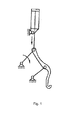
Fig. 1 is a diagram showing a tire dismounting hook apparatus according to a prior art; -
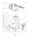
Fig. 2 is a diagram showing an incomplete exploded view of a tire dismounting hook apparatus according to the present invention; -
Fig. 3 is a diagram showing a configuration of a tire dismounting hook apparatus according to the present invention; -
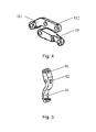
Fig. 4 is a diagram showing a linkage mechanism of a tire dismounting hook apparatus according to the present invention; and -
Fig. 5 is a diagram showing a configuration of a tire dismounting hook included in the tire dismounting hook apparatus. - 1-tube assembly, 2-cylinder, 3-stand, 4-countersunk head screw, 5-tire dismounting device bird head, 6-rim protection mat, 7-screw pin, 8-small countersunk head screw, 9-tire dismounting hook, 91-first hinge hole, 92-second hinge hole, 93-hook shape member, 10-second swing arm, 11-first swing arm, 111-first portion, 112-second portion, 12-short hinge shaft, 121-first short hinge shaft, 122-second short hinge shaft, 123-third short hinge shaft, 13-long hinge shaft, 131-first long hinge shaft, 132-second long hinge shaft, 14-shield ring, 15-roll shaft, 16-roll wheel, 17-curved lever, 18-fastening screw, 19-spring pad, 20-drive shaft, 21-piston rod joint, 22-hexagonal slim nut, 23- hexagonal nut, 24-control valve assembly, 25-cap nut.
- To make the objects, the technical solutions and the advantages of the present invention more apparent, the following will describe embodiments of the present invention with reference to accompanying drawings.
- As shown in
Fig. 1 , a structure of a pneumatic tire dismounting hook apparatus according to a prior art is typical four-bar tire dismounting mechanism. The pneumatic tire dismounting hook apparatus according to the prior art has a simple structure and provides a practicability and a credibility, but has the following shortcomings. First, a lower hinge hole of a cylinder piston rod, an upper hinge hole of an upper rocker, an upper hinge hole of a hook form a common hinge joint. Since the three hinge holes are arranged in a horizontal direction, a size of the common hinge joint in the horizontal direction is increased. In order to accommodate an up-and-down movement of the piston rod, a horizontal dimension of a stand of the tire dismounting hook needs to be increased. However, when the horizontal dimension of a stand of the tire dismounting hook is increased, the stand of the tire dismounting hook interferes with a tire of a vehicle during dismounting of the tire. Second, a hinge joint structure makes a front portion of the cylinder being hanged when the cylinder is mounted. Thus, during an operation of the cylinder, the piston rod continually swings during an expand operation and a retract operation with a position change of the common hinge joint. With an increase of use time, a service life of the cylinder is shortened by an inevitable unilateral wear and tear. - The tire dismounting hook apparatus according to an embodiment of the present invention reduces a body size of the mechanism, improves an assembly technique, makes structures compact, provides stable and reliable performance, provides improved fire dismounting operation, improves an operating condition of the cylinder, and extends a service life of the cylinder.
- As shown in
Fig. 2 to Fig. 5 , a tire dismounting hook apparatus according to an embodiment of the present invention is applied to a tire dismounting device. The tire dismounting hook apparatus includes acylinder 2 and atube assembly 1 connected with thecylinder 2. - The tire dismounting hook apparatus further includes a stand connected with one end of the
cylinder 2 which is positioned close to a piston rod of thecylinder 2. Acurved lever 17 hinged with the piston rod is provided in thestand 3. An arc groove having a predetermined width is disposed on thecurved lever 17, aroll wheel 16 is disposed in the arc groove in contact with an inner wall of the arc groove, aroll shaft 15 corresponding to theroll wheel 16 is disposed in thestand 3, and theroll shaft 15 penetrates through theroll wheel 16. A linkage mechanism hinged with one end of thecurved bar 17 which is positioned apart from the piston rod, One end of the linkage mechanism, which is positioned apart from thecurved lever 17, extends to an outside of thestand 3. Atire dismounting hook 9 hinged with the one end of the linkage mechanism which is positioned apart from thecurved bar 17. When a piston of thecylinder 2 protrudes, the piston rod drives thecurved lever 17 to move in a protruding direction of the piston and thecurved lever 17 moves along the arc groove in a direction moving away from the piston rod causing a movement of thetire dismounting hook 9 in the protruding direction of the piston and in the direction moving away from the piston rod. - In the dismounting hook apparatus according to the embodiment of the present invention, when gas is charged to the
cylinder 2 via thetube assembly 1 and the piston of thecylinder 2 protrudes, the piston rod drives thecurved lever 17 to move in a protruding direction of the piston, and at the same time, theroll wheel 16 disposed on thecurved lever 17 rolls on theroll shaft 15 causing a movement of thecurved lever 17 along the arc groove in a direction moving away from the piston rod. Thus, thecurved lever 17 drives thetire dismounting hook 9 to move in the protruding direction of the piston and in the direction moving away from the piston rod. - When the gas in the
cylinder 2 is discharged via thetube assembly 1 and the piston retracts, the piston rod drives thecurved lever 17 to move in a retracting direction of the piston. At the same time, theroll wheel 16 disposed on thecurved lever 17 rolls on theroll shaft 15, and drives thecurved lever 17 to move along arc groove in a direction approaching to the piston rod. Thus, thecurved lever 17 drives thetire dismount hook 9 to move in the retracting direction of the piston and in the direction approaching to the piston rod. - With above-described configuration, a flexibility of using the tire
dismounting hook apparatus 9 is improved, a size of the tire dismounting hook apparatus reduced, an assembly process is improved, an interference between thestand 3 and a tire is avoided, an efficiency of tire dismounting work is improved, and a service life of thecylinder 2 is extended. Specifically, thestand 3 is provided by a welded element. Thus, a robustness of the tire dismounting hook apparatus is secured. - The
roll wheel 16 is able to roll along the arc groove. For example, a diameter of theroll wheel 16 is equal to a width of the arc groove. - Preferably, the
cylinder 2 is connected with thestand 3 by a flange structure. - In this case, the
cylinder 2 may be fixed to an upper portion of thestand 3 in a flange fastening manner at its front end. With this structure, a movement of the piston rod is pure expanding and retracting operation. Thus, compared with a structure in which thecylinder 2 is equipped in a front-hanged or rear-hanged manner, using flange fastening manner to fix the front end provides a simple assembly, adjustment and maintenance. Further, since a working condition of thecylinder 2 is improved, the service life of thecylinder 2 is extended. - According to an embodiment of the present disclosure, the linkage mechanism may include a
first swing arm 11 and asecond swing arm 10, each of which is hinged with thestand 3 at one end and is hinged with thetire dismounting hook 9 at the other end. Thesecond swing arm 10 is disposed under thefirst swing arm 11 and is disposed farther than thefirst swing arm 11 with respect to thecurved lever 17. The one end of thecurved lever 17, which is positioned apart from the piston rod, is hinged with an arm body of thefirst swing arm 11. - At this time, when the
curved lever 17 moves together with the piston of thecylinder 2, thefirst swing arm 11, under an operation of thecurved lever 17, drives thetire dismounting hook 9 to generate a relative movement. Thus, a normal use of the tire dismounting hook is achieved, and thesecond swing arm 10 secures a stability of thetire dismounting hook 9 during the movement in order to restrict a random swing movement of the tire dismounting hook. Thus, an efficiency of the tire dismounting work is improved, and a stability of the apparatus is improved. - The
first swing arm 11 is hinged with afirst hinge hole 91 of thetire dismounting hook 9, which is apart from thehook shape member 93. Thesecond swing arm 10 is hinged with asecond hinge hole 92 of thetire dismounting hook 9. Thesecond hinge hole 92 is disposed between thefirst hinge hole 91 and thehook shape member 93. - Further, the
first swing arm 11 may be hinged with thestand 3 via a firstlong hinge shaft 131 at an inside portion of thestand 3. The firstlong hinge shaft 131 may be fixed using afastening screw 18. Thesecond swing arm 10 may be hinged with thestand 3 via a secondlong hinge shaft 132 at an inside portion of thestand 3. The secondlong hinge shaft 132 may be fixed using afastening screw 18. Thefirst hinge hole 91 of thetire dismounting hook 9 may be hinged with thefirst swing arm 11 by a firstshort hinge shaft 121. The firstshort hinge shaft 121 may be fixed using afastening screw 18. Thesecond hinge hole 92 of thetire dismounting hook 9 may be hinged with thesecond swing arm 10 by a secondshort hinge shaft 122. The secondshort hinge shaft 122 may be fixed using afastening screw 18. Thecurved lever 17 may be hinged with the arm body of thefirst swing arm 11 by a thirdshort hinge shaft 123. The thirdshort hinge shaft 123 may be fixed using afastening screw 18. - With above configuration, a stability of the hinge structure is improved by the
long hinge shaft 13,short hinge shaft 12 and the fastening screws 18. - Specifically, the
first swing arm 11 includes afirst portion 111 and asecond portion 112 angled with each other by a predetermined angle. One end of thefirst portion 111, which is apart from thesecond portion 112, is hinged with thestand 3. One end of thesecond portion 112, which is apart from thefirst portion 111, is hinged with thetire dismounting hook 9. Thesecond swing arm 10 is disposed parallel to thesecond portion 112. - With above configuration, since the
second swing arm 10 is parallel to thesecond portion 112 of thefirst swing arm 11, an interference between the two parts is avoided. Thus, a stable control to thetire dismounting hook 9 is secured, operability is improved, and tire dismounting quality is improved. - In an embodiment of the present invention, two ends of the
roll shaft 15 are fixed to thestand 3 in one horizontal direction, and ashield ring 14 is disposed at a fix position of theroll shaft 15 to thestand 3. - With above configuration, the roll shaft is connected with the
stand 3 in a two-ends supporting manner. Thus, a stability of the connection is secured. Further, at a fix position of theroll shaft 15 to thestand 3, theshield ring 14 is disposed. Theshield ring 14 may be provided by a elastic shield ring. Thus, a bearing pressure at the fix position between theroll shaft 15 and thestand 3 is reduced. With this configuration, a damage caused by an interaction force between theroll shaft 15 and thestand 3 is avoided, and a stability and safety of the apparatus is improved. - In an embodiment of the present invention, the
curved lever 17 is hinged with the piston rod via a piston rod joint 21, and aspring pad 19 is disposed at a hinge position between thecurved lever 17 and the piston rod joint 21. - With above configuration, since the
curved lever 17 is hinged with the piston rod via the piston rod joint 21, the apparatus provides a simple mounting and dismounting, provides an easy replacement and adjustment, and improves an usefulness. Since thespring pad 19 is disposed at the hinge position between thecurved lever 17 and the piston rod joint 21, an improved cushioning effect is provided and a stability of the apparatus is improved. - Specifically, the
curved lever 17 may be hinged with the piston rod joint 21 via adrive shaft 20 . The piston rod joint 21 may be connected with the piston rod via a hexagonalslim nut 22. This configuration secures a mounting stability, simplifies a dismounting work, and provides easy adjustment. - According to an embodiment of the present invention, the tire dismounting hook apparatus may further include a tire dismounting
device bird head 5. The tire dismountingdevice bird head 5 is connected with one end of thestand 3, which is positioned apart from thecylinder 2. The tire dismountingdevice bird head 5 is also disposed on a first surface of thestand 3, which is positioned opposite to the piston rod. - With above configuration, the tire dismounting
device bird head 5 improves an operation precision of the apparatus with respect to the tire, and enables a smooth and speedy tire dismounting work. The tire dismountingdevice bird head 5 is disposed on the surface of thestand 3, which is opposite to the piston rod. Thus, an operation of thetire dismounting hook 9 is not adversely affected by the dismountingdevice bird head 5, achieves a proper arrangement of the components, and a stable operation of the apparatus. - In an embodiment of the present invention, the tire dismounting hook apparatus may further include a
rim protection mat 6 connected with the one end of thestand 3, which is positioned apart from thecylinder 2, and connected with the tire dismountingdevice bird head 5. Therim protection mat 6 is disposed on a second surface of thestand 3, which is positioned opposite to thecylinder 2. - With above configuration, during the dismounting of the tire, the
rim protection mat 6 protects a rim of the tire, and secures a safety and stability during the dismounting of the tire and improves a tire dismounting quality. Therim protection mat 6 is disposed on the surface of the stand 3opposite to thecylinder 2. Thus, an operation of thetire dismounting hook 9 and the tire dismountingdevice bird head 5 is not adversely affected by therim protection mat 6, and achieves a proper arrangement of the components, and secures a stable operation of the apparatus. - Specifically, the tire dismounting
device bird head 5 may be fixed to thestand 3 via multiple countersunk head screws 4. One end of therim protection mat 6 may be connected with the tire dismountingdevice bird head 5 through ascrew pin 7. The other end of therim protection mat 6 may be fixed to thestand 3 via multiple small countersunk head screws 8. This configuration provides a stable mounting and also provides a simple dismounting. - In order to provide a proper control for the
cylinder 2, the tire dismounting hook apparatus may further include acontrol valve assembly 24 that controls an operation state of the cylinder 2and is connected with thecylinder 2. - With above configuration, a simple control for the
cylinder 2 is provided by thecontrol valve assembly 24. Accordingly, the configuration proves a simple operation to the user, and improves a practicality and convenience of the apparatus. - Specifically, the
control valve assembly 24 may be attached to a side surface of thecylinder 2 via ahexagonal nut 23 and acap nut 25. Accordingly, the configuration secures a mounting stability and simple dismounting, and will not affect a normal operation of other components. - The following will describe an example of a specific embodiment of the present invention.
- As shown in
Fig. 2 to Fig. 5 , the tire dismounting hook apparatus according to one embodiment of the present invention includes acylinder 2 and atube assembly 1 connected with thecylinder 2, acontrol valve assembly 24 fixed to the side surface of thecylinder 2 via thehexagonal nut 23 and thecap nut 25. The tire dismounting hook apparatus further includes astand 3 connected with one end of thecylinder 2, which is positioned close to the piston rod of thecylinder 2, a tire dismountingdevice bird head 5 connected with one end of thestand 3, which is positioned apart from thecylinder 2, arim protection mat 6 respectively connected with thestand 3 and the tire dismountingdevice bird head 5. Thecylinder 2 is fixed to the upper portion of thestand 3 in a flange fastening manner at its front end. The tire dismountingdevice bird head 5 is fixed to the side surface of the lower portion of thestand 3 via four countersunk head screws 4. One end of therim protection mat 6 is connected with the tire dismountingdevice bird head 5 via the screw pin penetrated through it. The other end of therim protection mat 6 is fixed to the lower portion of thestand 3 via the small countersunkhead screw 8. - In the
stand 3, thecurved lever 17 is disposed. Thecurved lever 17 is hinged with the piston rod joint 21 via thedrive shaft 20. Thespring pad 19 is disposed between them to prevent them from loosing. The piston rod joint 21 is connected with the piston rod of thecylinder 2 through the hexagonalslim nut 22. On the curved lever, the arc groove having a predetermined width is disposed. In the arc groove, theroll wheel 16 is disposed in contact with the inner wall of the arc groove. In the stand, theroll shaft 15 corresponding to theroll wheel 16 is disposed. Theroll shaft 15 penetrates through theroll wheel 16. Two ends of theroll shaft 15 are fixed to thestand 3 in one horizontal direction viaelastic shield rings Theroll wheel 16 has the diameter, which is equal to the width of the arc groove, so that theroll wheel 16 rolls along the arc groove. - The linkage mechanism is hinged with one end of the curved lever, which is positioned apart from the piston rod. One end of the linkage mechanism, which is positioned apart from the
curved lever 17, extends to an outside of thestand 3 and is hinged with thetire dismounting hook 9 . The linkage mechanism includes thefirst swing arm 11 and thesecond swing arm 10. Thecurved lever 17 is hinged with the arm body of thefirst swing arm 11. Thefirst swing arm 11 includes thefirst portion 111 and thesecond portion 112 angled with each other by a predetermined angle. One end of thefirst portion 111, which is apart from thesecond portion 112, is hinged with thestand 3. One end of thesecond portion 112, which is apart from thefirst portion 111, is hinged with thefirst hinge hole 91 of thetire dismounting hook 9. Thesecond swing arm 10 is disposed under thefirst swing arm 11, and is disposed farther than thefirst swing arm 11 with respect to thecurved lever 17. Thesecond swing arm 10 is disposed parallel to thesecond portion 112 of thefirst swing arm 11. One end of thesecond swing arm 10 is hinged with thestand 3, and the other end of thesecond swing arm 10 is hinged with thesecond hinge hole 92 of thetire dismounting hook 9. Thesecond hinge hole 92 is disposed between thefirst hinge hole 91 and thehook shape member 93 of thetire dismounting hook 9. - The
first swing arm 11 is hinged with thestand 3 via the firstlong hinge shaft 131 in thestand 3. Thesecond swing arm 10 is hinged with thestand 3 via the secondlong hinge shaft 132 in thestand 3. Thefirst hinge hole 91 of thetire dismounting hook 9 is hinged with thefirst swing arm 11 by the firstshort hinge shaft 121. Thesecond hinge hole 92 of thetire dismounting hook 9 is hinged with thesecond swing arm 10 by the secondshort hinge shaft 122. Thecurved lever 17 is hinged with the arm body of thefirst swing arm 11 by the thirdshort hinge shaft 123. The firstlong hinge shaft 131, the secondlong hinge shaft 132, the firstshort hinge shaft 121, the secondshort hinge shaft 122, the thirdshort hinge shaft 123 are fixed by the fastening screws 18. - When using the apparatus, the
control valve assembly 24 controls the piston rod of thecylinder 2 to protrude out and move in a downward direction. Thus, the piston rod joint 21 moves downward in a vertical direction. An protruding force is applied to thecurved lever 17 via thedrive shaft 20. Thus, thecurved lever 17 moves in the downward direction. Since theroll shaft 15 is hinged with thestand 3 and theroll wheel 16 is only able to perform a rolling movement, thecurved lever 17 moves downward under an operation of the arc groove, and at the same time, swings outward with thedrive shaft 20 as an axis. Thefirst swing arm 11, under an operation of thecurved lever 17, drives thetire dismounting hook 9 to move downward. - When operating the
control valve assembly 24 in an opposite direction to make thepiston rod 2 retract and move in an upward direction, the piston rod joint 21 moves upward in the vertical direction. A retract force is applied to thecurved lever 17 via thedrive shaft 20. Thus, the curved lever moves upward. Since theroll shaft 15 is hinged with thestand 3 and theroll wheel 16 is only able to perform a rolling movement, thecurved lever 17 moves upward under an operation of the arc groove, and at the same time, swings inward with thedrive shaft 20 as an axis. Thefirst swing arm 11, under an operation of thecurved lever 17, drives thetire dismounting hook 9 to move upward. - The tire dismounting hook apparatus according to foregoing embodiments of the present invention reduces a size of the tire dismounting hook apparatus, improves an assembly process, provides a stable performance compact structure, provides a stable and reliable performance, provides a simple adjustment and maintenance, improves an efficiency of tire dismounting work, and improves a working condition of the
cylinder 2, and extends a service life of the cylinder. - The tire dismounting hook apparatus according to the present invention is applied to a tire dismounting device. Thus, according to another embodiment of the present invention, a tire dismounting device including the above-described tire dismounting hook apparatus is provided. All of the foregoing embodiments that provide the tire dismounting hook apparatus are also applied to the embodiment of the tire dismounting device, and provide similar technical advantages.
- The above is a preferred embodiment of the present invention, it should be noted that for a person skilled in the art, improvements and modifications can be made based on the present invention without departing from a principle of the present invention. The improvements and the modifications are also regarded as included in a protection scope of the present invention.
Claims (10)
- A tire dismounting hook apparatus applied to a tire dismounting device, comprising
a cylinder (2),
a tube assembly (1) connected with the cylinder (2),
a stand (3) connected with one end of the cylinder (2) closing to a piston rod of the cylinder (2);
a curved lever (17) disposed in the stand (3) and hinged with the piston rod; wherein, an arc groove having a predetermined width being disposed on the curved lever (17), a roll wheel (16) being disposed in the arc groove in contact with an inner wall of the arc groove, and a roll shaft (15) corresponding to the roll wheel (16) being disposed in the stand (3), the roll shaft (15) penetrating through the roll wheel (16);
a linkage mechanism hinged with one end of the curved lever (17) apart from the piston rod, one end of the linkage mechanism apart from the curved lever (17) extending out of the stand (3); and
a tire dismounting hook (9) hinged with the one end of the linkage mechanism apart from the curved lever (17),
when a piston of the cylinder (2) protrudes, the piston rod drives the curved lever (17) to move in a protruding direction of the piston and the curved lever (17) moves along the arc groove in a direction moving away from the piston rod, and the curved lever (17) drives the tire dismounting hook (9) to move in the protruding direction of the piston and in the direction moving away from the piston rod. - The tire dismounting hook apparatus according to claim 1, wherein, the cylinder (2) is connected with the stand (3) by a flange structure.
- The tire dismounting hook apparatus according to claim 1, wherein, the linkage mechanism further comprises:a first swing arm (11) and a second swing arm (10), each of which is hinged with the stand (3) at one end and is hinged with the tire dismounting hook (9) at the other end, wherein:the second swing arm (10) is disposed under the first swing arm (11) and is disposed farther than the first swing arm (11) with respect to the curved lever (17);the one end of the curved lever (17) apart from the piston rod, is hinged with an arm body of the first swing arm (11).
- The tire dismounting hook apparatus according to claim 3, wherein,
the first swing arm (11) comprises a first portion (111) and a second portion (112) angled with each other by a predetermined angle, one end of the first portion (111) apart from the second portion (112) is hinged with the stand (3), and one end of the second portion (112) apart from the first portion (111) is hinged with the tire dismounting hook (9); and
the second swing arm (10) is disposed parallel to the second portion (112). - The tire dismounting hook apparatus according to claim 1, wherein, two ends of the roll shaft (15) are fixed to the stand (3) in one horizontal direction, and shield rings (14) are disposed at fix positions at which the roll shaft (15) is fixed to the stand (3).
- The tire dismounting hook apparatus according to claim 1, wherein, the curved lever (17) is hinged with the piston rod via a piston rod joint (21), and a spring pad (19) is disposed at a hinge position between the curved lever (17) and the piston rod joint (21).
- The tire dismounting hook apparatus according to claim 1, further comprising:a tire dismounting device bird head (5) connected with one end of the stand (3) and disposed on a first surface of the stand (3), the one end of the stand (3) being positioned apart from the cylinder (2), and the first surface being a surface that is positioned opposite to the piston rod.
- The tire dismounting hook apparatus according to claim 7, further comprising:a rim protection mat (6) connected with the one end of the stand (3) apart from the cylinder (2), and connected with the tire dismounting device bird head (5), the rim protection mat (6) being disposed on a second surface of the stand (3), the second surface being a surface that is positioned opposite to the cylinder (2).
- The tire dismounting hook apparatus according to claim 1, further comprising:a control valve assembly (24) that is connected with the cylinder (2) and controls an operation state of the cylinder (2).
- A tire dismounting device, comprising the tire dismounting hook apparatus according to any one of claims 1 to 9.
Applications Claiming Priority (1)
| Application Number | Priority Date | Filing Date | Title |
|---|---|---|---|
| CN201410354045.9A CN105437886B (en) | 2014-07-22 | 2014-07-22 | One kind tears tire hook device and tyre detacher open |
Publications (2)
| Publication Number | Publication Date |
|---|---|
| EP2977235A1 true EP2977235A1 (en) | 2016-01-27 |
| EP2977235B1 EP2977235B1 (en) | 2016-10-12 |
Family
ID=51564464
Family Applications (1)
| Application Number | Title | Priority Date | Filing Date |
|---|---|---|---|
| EP14184384.7A Not-in-force EP2977235B1 (en) | 2014-07-22 | 2014-09-11 | Tire dismounting hook apparatus and tire dismounting device |
Country Status (4)
| Country | Link |
|---|---|
| EP (1) | EP2977235B1 (en) |
| CN (1) | CN105437886B (en) |
| ES (1) | ES2604982T3 (en) |
| PL (1) | PL2977235T3 (en) |
Cited By (3)
| Publication number | Priority date | Publication date | Assignee | Title |
|---|---|---|---|---|
| CN109209817A (en) * | 2018-11-20 | 2019-01-15 | 泉州苗亿自动化机械有限公司 | A kind of soundproof oil free air compressor |
| CN109968927A (en) * | 2019-04-16 | 2019-07-05 | 杨新伟 | A kind of truck tyre changer |
| EP4480720A1 (en) * | 2023-06-19 | 2024-12-25 | Femas S.r.l. | Device for removing and mounting tires from/onto rims |
Families Citing this family (4)
| Publication number | Priority date | Publication date | Assignee | Title |
|---|---|---|---|---|
| CN105946475A (en) * | 2016-06-24 | 2016-09-21 | 陕西理工大学 | Removing device for insertions in trenches on surface of tire |
| CN107804124B (en) * | 2017-11-24 | 2023-10-20 | 苏州市职业大学 | Multifunctional manual tire dismounting device |
| CN112895820A (en) * | 2021-03-22 | 2021-06-04 | 科星汽车设备(珠海)有限公司 | Pneumatic pinch-free tire dismounting head structure |
| CN115416434B (en) * | 2022-09-19 | 2023-11-14 | 伺轮智能机器人(南京)有限公司 | Self-adaptation tire dismouting manipulator |
Citations (3)
| Publication number | Priority date | Publication date | Assignee | Title |
|---|---|---|---|---|
| CN200957750Y (en) * | 2006-10-08 | 2007-10-10 | 科星(中山)汽车设备有限公司 | Tyre-lip detacher |
| EP2233325A1 (en) * | 2009-03-27 | 2010-09-29 | SICAM S.r.l. | Machine for fitting and removing the wheel tyres of vehicle |
| EP2735457A1 (en) * | 2012-11-27 | 2014-05-28 | Sino-Italian Taida (Yingkow) Garage Equipment Co., Ltd. | Tyre changing apparatus |
Family Cites Families (2)
| Publication number | Priority date | Publication date | Assignee | Title |
|---|---|---|---|---|
| US7712510B2 (en) * | 2006-09-15 | 2010-05-11 | Android Industries Llc | Tire installation tool |
| CN202935102U (en) * | 2012-12-03 | 2013-05-15 | 中意泰达(营口)汽车保修设备有限公司 | Tire dismounting device |
-
2014
- 2014-07-22 CN CN201410354045.9A patent/CN105437886B/en active Active
- 2014-09-11 ES ES14184384.7T patent/ES2604982T3/en active Active
- 2014-09-11 EP EP14184384.7A patent/EP2977235B1/en not_active Not-in-force
- 2014-09-11 PL PL14184384T patent/PL2977235T3/en unknown
Patent Citations (3)
| Publication number | Priority date | Publication date | Assignee | Title |
|---|---|---|---|---|
| CN200957750Y (en) * | 2006-10-08 | 2007-10-10 | 科星(中山)汽车设备有限公司 | Tyre-lip detacher |
| EP2233325A1 (en) * | 2009-03-27 | 2010-09-29 | SICAM S.r.l. | Machine for fitting and removing the wheel tyres of vehicle |
| EP2735457A1 (en) * | 2012-11-27 | 2014-05-28 | Sino-Italian Taida (Yingkow) Garage Equipment Co., Ltd. | Tyre changing apparatus |
Cited By (4)
| Publication number | Priority date | Publication date | Assignee | Title |
|---|---|---|---|---|
| CN109209817A (en) * | 2018-11-20 | 2019-01-15 | 泉州苗亿自动化机械有限公司 | A kind of soundproof oil free air compressor |
| CN109209817B (en) * | 2018-11-20 | 2023-09-29 | 泉州苗亿自动化机械有限公司 | Mute oil-free air compressor |
| CN109968927A (en) * | 2019-04-16 | 2019-07-05 | 杨新伟 | A kind of truck tyre changer |
| EP4480720A1 (en) * | 2023-06-19 | 2024-12-25 | Femas S.r.l. | Device for removing and mounting tires from/onto rims |
Also Published As
| Publication number | Publication date |
|---|---|
| CN105437886A (en) | 2016-03-30 |
| PL2977235T3 (en) | 2017-02-28 |
| CN105437886B (en) | 2017-08-04 |
| ES2604982T3 (en) | 2017-03-10 |
| EP2977235B1 (en) | 2016-10-12 |
Similar Documents
| Publication | Publication Date | Title |
|---|---|---|
| EP2977235B1 (en) | Tire dismounting hook apparatus and tire dismounting device | |
| CN110822244B (en) | Adjustable cantilever device | |
| JP5890936B1 (en) | Aircraft passenger seat | |
| RU2015144693A (en) | DEVICE FOR TRAINING MUSCLES | |
| CN205095855U (en) | Grinding roller rolling distance adjustment mechanism and milling machine | |
| JP2013223282A (en) | Pantograph for railroad car | |
| KR200474484Y1 (en) | Roller pivot structure | |
| TW451032B (en) | Fluid pressure cylinder with adjustable stroke | |
| CN203751417U (en) | Internal slicing machine | |
| IT201900001731A1 (en) | SUPPORT HANGER FOR A SUSPENDED CONTACT WIRE OF A RAILWAY ELECTRIC POWER SUPPLY LINE AND RAILWAY ELECTRIC AERIAL LINE INCLUDING THIS HANGER | |
| CN102784874B (en) | Hand-held electromagnetic riveting gun buffering and guiding mechanism | |
| CN202845686U (en) | Buffering and guiding mechanism of electromagnetism riveter | |
| CN106552692B (en) | Grinding roller roll clearance adjusting mechanism and flour mill | |
| CN201448315U (en) | Tension-compression fixer | |
| CN207998404U (en) | A kind of auxiliary hoisting device of turbine high-pressure valve assembly | |
| CN211714848U (en) | Door hinge applied to dish washing machine | |
| CN210240402U (en) | Hanger shock absorber | |
| CN208147467U (en) | A kind of swing transverse direction feeding mechanism pushing bearing ring | |
| CN206598780U (en) | A kind of novel automobile rear view mirror device | |
| CN204847824U (en) | Crane outrigger adjusting device | |
| CN212255914U (en) | Pull rod anticreep anti-swing anti-sticking formula spectacle frame catapult | |
| CN204384832U (en) | Safety supports assembly | |
| CN206399384U (en) | A kind of silicon pole crest line detection means and silicon pole cutting equipment | |
| CN213178579U (en) | Air conditioner wind shield | |
| CN214365566U (en) | Damping hinge for cabinet door |
Legal Events
| Date | Code | Title | Description |
|---|---|---|---|
| PUAI | Public reference made under article 153(3) epc to a published international application that has entered the european phase |
Free format text: ORIGINAL CODE: 0009012 |
|
| 17P | Request for examination filed |
Effective date: 20140911 |
|
| AK | Designated contracting states |
Kind code of ref document: A1 Designated state(s): AL AT BE BG CH CY CZ DE DK EE ES FI FR GB GR HR HU IE IS IT LI LT LU LV MC MK MT NL NO PL PT RO RS SE SI SK SM TR |
|
| AX | Request for extension of the european patent |
Extension state: BA ME |
|
| GRAP | Despatch of communication of intention to grant a patent |
Free format text: ORIGINAL CODE: EPIDOSNIGR1 |
|
| INTG | Intention to grant announced |
Effective date: 20160426 |
|
| GRAS | Grant fee paid |
Free format text: ORIGINAL CODE: EPIDOSNIGR3 |
|
| GRAA | (expected) grant |
Free format text: ORIGINAL CODE: 0009210 |
|
| AK | Designated contracting states |
Kind code of ref document: B1 Designated state(s): AL AT BE BG CH CY CZ DE DK EE ES FI FR GB GR HR HU IE IS IT LI LT LU LV MC MK MT NL NO PL PT RO RS SE SI SK SM TR |
|
| REG | Reference to a national code |
Ref country code: GB Ref legal event code: FG4D |
|
| REG | Reference to a national code |
Ref country code: CH Ref legal event code: EP |
|
| REG | Reference to a national code |
Ref country code: AT Ref legal event code: REF Ref document number: 836152 Country of ref document: AT Kind code of ref document: T Effective date: 20161015 |
|
| REG | Reference to a national code |
Ref country code: IE Ref legal event code: FG4D |
|
| REG | Reference to a national code |
Ref country code: DE Ref legal event code: R096 Ref document number: 602014004187 Country of ref document: DE |
|
| REG | Reference to a national code |
Ref country code: NL Ref legal event code: FP |
|
| REG | Reference to a national code |
Ref country code: CH Ref legal event code: NV Representative=s name: WEINMANN ZIMMERLI, CH |
|
| REG | Reference to a national code |
Ref country code: LT Ref legal event code: MG4D |
|
| PG25 | Lapsed in a contracting state [announced via postgrant information from national office to epo] |
Ref country code: LV Free format text: LAPSE BECAUSE OF FAILURE TO SUBMIT A TRANSLATION OF THE DESCRIPTION OR TO PAY THE FEE WITHIN THE PRESCRIBED TIME-LIMIT Effective date: 20161012 |
|
| REG | Reference to a national code |
Ref country code: ES Ref legal event code: FG2A Ref document number: 2604982 Country of ref document: ES Kind code of ref document: T3 Effective date: 20170310 |
|
| REG | Reference to a national code |
Ref country code: AT Ref legal event code: MK05 Ref document number: 836152 Country of ref document: AT Kind code of ref document: T Effective date: 20161012 |
|
| PG25 | Lapsed in a contracting state [announced via postgrant information from national office to epo] |
Ref country code: GR Free format text: LAPSE BECAUSE OF FAILURE TO SUBMIT A TRANSLATION OF THE DESCRIPTION OR TO PAY THE FEE WITHIN THE PRESCRIBED TIME-LIMIT Effective date: 20170113 Ref country code: SE Free format text: LAPSE BECAUSE OF FAILURE TO SUBMIT A TRANSLATION OF THE DESCRIPTION OR TO PAY THE FEE WITHIN THE PRESCRIBED TIME-LIMIT Effective date: 20161012 Ref country code: NO Free format text: LAPSE BECAUSE OF FAILURE TO SUBMIT A TRANSLATION OF THE DESCRIPTION OR TO PAY THE FEE WITHIN THE PRESCRIBED TIME-LIMIT Effective date: 20170112 Ref country code: LT Free format text: LAPSE BECAUSE OF FAILURE TO SUBMIT A TRANSLATION OF THE DESCRIPTION OR TO PAY THE FEE WITHIN THE PRESCRIBED TIME-LIMIT Effective date: 20161012 |
|
| PG25 | Lapsed in a contracting state [announced via postgrant information from national office to epo] |
Ref country code: PT Free format text: LAPSE BECAUSE OF FAILURE TO SUBMIT A TRANSLATION OF THE DESCRIPTION OR TO PAY THE FEE WITHIN THE PRESCRIBED TIME-LIMIT Effective date: 20170213 Ref country code: HR Free format text: LAPSE BECAUSE OF FAILURE TO SUBMIT A TRANSLATION OF THE DESCRIPTION OR TO PAY THE FEE WITHIN THE PRESCRIBED TIME-LIMIT Effective date: 20161012 Ref country code: AT Free format text: LAPSE BECAUSE OF FAILURE TO SUBMIT A TRANSLATION OF THE DESCRIPTION OR TO PAY THE FEE WITHIN THE PRESCRIBED TIME-LIMIT Effective date: 20161012 Ref country code: FI Free format text: LAPSE BECAUSE OF FAILURE TO SUBMIT A TRANSLATION OF THE DESCRIPTION OR TO PAY THE FEE WITHIN THE PRESCRIBED TIME-LIMIT Effective date: 20161012 Ref country code: BE Free format text: LAPSE BECAUSE OF FAILURE TO SUBMIT A TRANSLATION OF THE DESCRIPTION OR TO PAY THE FEE WITHIN THE PRESCRIBED TIME-LIMIT Effective date: 20161012 Ref country code: IS Free format text: LAPSE BECAUSE OF FAILURE TO SUBMIT A TRANSLATION OF THE DESCRIPTION OR TO PAY THE FEE WITHIN THE PRESCRIBED TIME-LIMIT Effective date: 20170212 Ref country code: RS Free format text: LAPSE BECAUSE OF FAILURE TO SUBMIT A TRANSLATION OF THE DESCRIPTION OR TO PAY THE FEE WITHIN THE PRESCRIBED TIME-LIMIT Effective date: 20161012 |
|
| REG | Reference to a national code |
Ref country code: DE Ref legal event code: R097 Ref document number: 602014004187 Country of ref document: DE |
|
| PG25 | Lapsed in a contracting state [announced via postgrant information from national office to epo] |
Ref country code: CZ Free format text: LAPSE BECAUSE OF FAILURE TO SUBMIT A TRANSLATION OF THE DESCRIPTION OR TO PAY THE FEE WITHIN THE PRESCRIBED TIME-LIMIT Effective date: 20161012 Ref country code: DK Free format text: LAPSE BECAUSE OF FAILURE TO SUBMIT A TRANSLATION OF THE DESCRIPTION OR TO PAY THE FEE WITHIN THE PRESCRIBED TIME-LIMIT Effective date: 20161012 Ref country code: SK Free format text: LAPSE BECAUSE OF FAILURE TO SUBMIT A TRANSLATION OF THE DESCRIPTION OR TO PAY THE FEE WITHIN THE PRESCRIBED TIME-LIMIT Effective date: 20161012 Ref country code: EE Free format text: LAPSE BECAUSE OF FAILURE TO SUBMIT A TRANSLATION OF THE DESCRIPTION OR TO PAY THE FEE WITHIN THE PRESCRIBED TIME-LIMIT Effective date: 20161012 Ref country code: RO Free format text: LAPSE BECAUSE OF FAILURE TO SUBMIT A TRANSLATION OF THE DESCRIPTION OR TO PAY THE FEE WITHIN THE PRESCRIBED TIME-LIMIT Effective date: 20161012 |
|
| PLBE | No opposition filed within time limit |
Free format text: ORIGINAL CODE: 0009261 |
|
| STAA | Information on the status of an ep patent application or granted ep patent |
Free format text: STATUS: NO OPPOSITION FILED WITHIN TIME LIMIT |
|
| PG25 | Lapsed in a contracting state [announced via postgrant information from national office to epo] |
Ref country code: SM Free format text: LAPSE BECAUSE OF FAILURE TO SUBMIT A TRANSLATION OF THE DESCRIPTION OR TO PAY THE FEE WITHIN THE PRESCRIBED TIME-LIMIT Effective date: 20161012 Ref country code: IT Free format text: LAPSE BECAUSE OF FAILURE TO SUBMIT A TRANSLATION OF THE DESCRIPTION OR TO PAY THE FEE WITHIN THE PRESCRIBED TIME-LIMIT Effective date: 20161012 Ref country code: BG Free format text: LAPSE BECAUSE OF FAILURE TO SUBMIT A TRANSLATION OF THE DESCRIPTION OR TO PAY THE FEE WITHIN THE PRESCRIBED TIME-LIMIT Effective date: 20170112 |
|
| 26N | No opposition filed |
Effective date: 20170713 |
|
| REG | Reference to a national code |
Ref country code: FR Ref legal event code: PLFP Year of fee payment: 4 |
|
| PG25 | Lapsed in a contracting state [announced via postgrant information from national office to epo] |
Ref country code: SI Free format text: LAPSE BECAUSE OF FAILURE TO SUBMIT A TRANSLATION OF THE DESCRIPTION OR TO PAY THE FEE WITHIN THE PRESCRIBED TIME-LIMIT Effective date: 20161012 |
|
| REG | Reference to a national code |
Ref country code: DE Ref legal event code: R081 Ref document number: 602014004187 Country of ref document: DE Owner name: CORWEI (YINGKOU) INDUSTRIAL CO., LTD., YINGKOU, CN Free format text: FORMER OWNER: BRIGHT TECHNOLOGY CO., LTD., YINGKOU CITY, LIAONING, CN |
|
| REG | Reference to a national code |
Ref country code: CH Ref legal event code: NV Representative=s name: FELBER UND PARTNER AG, CH Ref country code: CH Ref legal event code: PUE Owner name: CORWEI (YINGKOU) INDUSTRIAL CO., LTD., CN Free format text: FORMER OWNER: BRIGHT TECHNOLOGY CO., LTD., CN |
|
| REG | Reference to a national code |
Ref country code: GB Ref legal event code: 732E Free format text: REGISTERED BETWEEN 20180405 AND 20180411 |
|
| PG25 | Lapsed in a contracting state [announced via postgrant information from national office to epo] |
Ref country code: MC Free format text: LAPSE BECAUSE OF FAILURE TO SUBMIT A TRANSLATION OF THE DESCRIPTION OR TO PAY THE FEE WITHIN THE PRESCRIBED TIME-LIMIT Effective date: 20161012 |
|
| REG | Reference to a national code |
Ref country code: ES Ref legal event code: PC2A Owner name: CORWEI (YINGKOU) INDUSTRIAL CO. LTD Effective date: 20180611 Ref country code: ES Ref legal event code: PC2A Effective date: 20180611 |
|
| REG | Reference to a national code |
Ref country code: IE Ref legal event code: MM4A |
|
| PG25 | Lapsed in a contracting state [announced via postgrant information from national office to epo] |
Ref country code: LU Free format text: LAPSE BECAUSE OF NON-PAYMENT OF DUE FEES Effective date: 20170911 |
|
| REG | Reference to a national code |
Ref country code: NL Ref legal event code: PD Owner name: CORWEI (YINGKOU) INDUSTRIAL CO., LTD.; CN Free format text: DETAILS ASSIGNMENT: CHANGE OF OWNER(S), ASSIGNMENT; FORMER OWNER NAME: BRIGHT TECHNOLOGY CO., LTD. Effective date: 20180517 |
|
| REG | Reference to a national code |
Ref country code: FR Ref legal event code: TP Owner name: CORWEI (YINGKOU) INDUSTRIAL CO., LTD., CN Effective date: 20180605 |
|
| REG | Reference to a national code |
Ref country code: FR Ref legal event code: PLFP Year of fee payment: 5 |
|
| PG25 | Lapsed in a contracting state [announced via postgrant information from national office to epo] |
Ref country code: IE Free format text: LAPSE BECAUSE OF NON-PAYMENT OF DUE FEES Effective date: 20170911 |
|
| PG25 | Lapsed in a contracting state [announced via postgrant information from national office to epo] |
Ref country code: MT Free format text: LAPSE BECAUSE OF NON-PAYMENT OF DUE FEES Effective date: 20170911 |
|
| PGFP | Annual fee paid to national office [announced via postgrant information from national office to epo] |
Ref country code: NL Payment date: 20180724 Year of fee payment: 5 Ref country code: DE Payment date: 20180731 Year of fee payment: 5 Ref country code: FR Payment date: 20180726 Year of fee payment: 5 |
|
| PGFP | Annual fee paid to national office [announced via postgrant information from national office to epo] |
Ref country code: CH Payment date: 20180926 Year of fee payment: 5 Ref country code: PL Payment date: 20180820 Year of fee payment: 5 Ref country code: GB Payment date: 20180928 Year of fee payment: 5 |
|
| PGFP | Annual fee paid to national office [announced via postgrant information from national office to epo] |
Ref country code: ES Payment date: 20181001 Year of fee payment: 5 |
|
| PG25 | Lapsed in a contracting state [announced via postgrant information from national office to epo] |
Ref country code: HU Free format text: LAPSE BECAUSE OF FAILURE TO SUBMIT A TRANSLATION OF THE DESCRIPTION OR TO PAY THE FEE WITHIN THE PRESCRIBED TIME-LIMIT; INVALID AB INITIO Effective date: 20140911 |
|
| PG25 | Lapsed in a contracting state [announced via postgrant information from national office to epo] |
Ref country code: CY Free format text: LAPSE BECAUSE OF FAILURE TO SUBMIT A TRANSLATION OF THE DESCRIPTION OR TO PAY THE FEE WITHIN THE PRESCRIBED TIME-LIMIT Effective date: 20161012 |
|
| PG25 | Lapsed in a contracting state [announced via postgrant information from national office to epo] |
Ref country code: MK Free format text: LAPSE BECAUSE OF FAILURE TO SUBMIT A TRANSLATION OF THE DESCRIPTION OR TO PAY THE FEE WITHIN THE PRESCRIBED TIME-LIMIT Effective date: 20161012 |
|
| PG25 | Lapsed in a contracting state [announced via postgrant information from national office to epo] |
Ref country code: TR Free format text: LAPSE BECAUSE OF FAILURE TO SUBMIT A TRANSLATION OF THE DESCRIPTION OR TO PAY THE FEE WITHIN THE PRESCRIBED TIME-LIMIT Effective date: 20161012 |
|
| REG | Reference to a national code |
Ref country code: DE Ref legal event code: R119 Ref document number: 602014004187 Country of ref document: DE |
|
| REG | Reference to a national code |
Ref country code: NL Ref legal event code: MM Effective date: 20191001 |
|
| REG | Reference to a national code |
Ref country code: CH Ref legal event code: PL |
|
| PG25 | Lapsed in a contracting state [announced via postgrant information from national office to epo] |
Ref country code: LI Free format text: LAPSE BECAUSE OF NON-PAYMENT OF DUE FEES Effective date: 20190930 Ref country code: CH Free format text: LAPSE BECAUSE OF NON-PAYMENT OF DUE FEES Effective date: 20190930 Ref country code: AL Free format text: LAPSE BECAUSE OF FAILURE TO SUBMIT A TRANSLATION OF THE DESCRIPTION OR TO PAY THE FEE WITHIN THE PRESCRIBED TIME-LIMIT Effective date: 20161012 Ref country code: NL Free format text: LAPSE BECAUSE OF NON-PAYMENT OF DUE FEES Effective date: 20191001 Ref country code: DE Free format text: LAPSE BECAUSE OF NON-PAYMENT OF DUE FEES Effective date: 20200401 |
|
| GBPC | Gb: european patent ceased through non-payment of renewal fee |
Effective date: 20190911 |
|
| PG25 | Lapsed in a contracting state [announced via postgrant information from national office to epo] |
Ref country code: GB Free format text: LAPSE BECAUSE OF NON-PAYMENT OF DUE FEES Effective date: 20190911 Ref country code: FR Free format text: LAPSE BECAUSE OF NON-PAYMENT OF DUE FEES Effective date: 20190930 |
|
| REG | Reference to a national code |
Ref country code: ES Ref legal event code: FD2A Effective date: 20210127 |
|
| PG25 | Lapsed in a contracting state [announced via postgrant information from national office to epo] |
Ref country code: ES Free format text: LAPSE BECAUSE OF NON-PAYMENT OF DUE FEES Effective date: 20190912 |
|
| PG25 | Lapsed in a contracting state [announced via postgrant information from national office to epo] |
Ref country code: PL Free format text: LAPSE BECAUSE OF NON-PAYMENT OF DUE FEES Effective date: 20190911 |