EP2977170A1 - Linkage mechanism between bottom die lifting and unilateral clamping - Google Patents
Linkage mechanism between bottom die lifting and unilateral clamping Download PDFInfo
- Publication number
- EP2977170A1 EP2977170A1 EP13879047.2A EP13879047A EP2977170A1 EP 2977170 A1 EP2977170 A1 EP 2977170A1 EP 13879047 A EP13879047 A EP 13879047A EP 2977170 A1 EP2977170 A1 EP 2977170A1
- Authority
- EP
- European Patent Office
- Prior art keywords
- machine frame
- bottom mould
- linkage
- rotation
- elevating
- Prior art date
- Legal status (The legal status is an assumption and is not a legal conclusion. Google has not performed a legal analysis and makes no representation as to the accuracy of the status listed.)
- Granted
Links
Images

Classifications
-
- B—PERFORMING OPERATIONS; TRANSPORTING
- B29—WORKING OF PLASTICS; WORKING OF SUBSTANCES IN A PLASTIC STATE IN GENERAL
- B29C—SHAPING OR JOINING OF PLASTICS; SHAPING OF MATERIAL IN A PLASTIC STATE, NOT OTHERWISE PROVIDED FOR; AFTER-TREATMENT OF THE SHAPED PRODUCTS, e.g. REPAIRING
- B29C49/00—Blow-moulding, i.e. blowing a preform or parison to a desired shape within a mould; Apparatus therefor
- B29C49/42—Component parts, details or accessories; Auxiliary operations
- B29C49/56—Opening, closing or clamping means
-
- B—PERFORMING OPERATIONS; TRANSPORTING
- B29—WORKING OF PLASTICS; WORKING OF SUBSTANCES IN A PLASTIC STATE IN GENERAL
- B29C—SHAPING OR JOINING OF PLASTICS; SHAPING OF MATERIAL IN A PLASTIC STATE, NOT OTHERWISE PROVIDED FOR; AFTER-TREATMENT OF THE SHAPED PRODUCTS, e.g. REPAIRING
- B29C49/00—Blow-moulding, i.e. blowing a preform or parison to a desired shape within a mould; Apparatus therefor
- B29C49/42—Component parts, details or accessories; Auxiliary operations
- B29C49/48—Moulds
- B29C2049/4879—Moulds characterised by mould configurations
- B29C2049/4892—Mould halves consisting of an independent main and bottom part
-
- B—PERFORMING OPERATIONS; TRANSPORTING
- B29—WORKING OF PLASTICS; WORKING OF SUBSTANCES IN A PLASTIC STATE IN GENERAL
- B29C—SHAPING OR JOINING OF PLASTICS; SHAPING OF MATERIAL IN A PLASTIC STATE, NOT OTHERWISE PROVIDED FOR; AFTER-TREATMENT OF THE SHAPED PRODUCTS, e.g. REPAIRING
- B29C49/00—Blow-moulding, i.e. blowing a preform or parison to a desired shape within a mould; Apparatus therefor
- B29C49/42—Component parts, details or accessories; Auxiliary operations
- B29C49/56—Opening, closing or clamping means
- B29C2049/566—Locking means
Landscapes
- Engineering & Computer Science (AREA)
- Manufacturing & Machinery (AREA)
- Mechanical Engineering (AREA)
- Moulds For Moulding Plastics Or The Like (AREA)
Abstract
Description
- The present invention relates to the field of a processing device for a beverage bottle, and more particularly to an elevating and locking mechanism for a bottom mould of a bottle blowing machine.
- A bottle blowing machine of the prior art generally comprises a machine frame, a left mould, a right mould and a bottom mould which are disposed on the machine frame, as well as a driving mechanism and a positioning mechanism. A bottom mould locking mechanism of a linear bottle blowing machine, as disclosed in patent publication No.
CN201755911U , comprises a mould mounting plate, a bottle mould, a bottom mould, an actuating mechansim, a positioning mechanism and a supporting seat. The end of the cavity of the bottle mould is sleeved with the bottom mould which is connected with the actuating mechanism. The positioning mechanism is horizontally disposed on the support seat and comprises a positioning block air cylinder and a positioning block connected with each other. The actuating mechanism comprises a bottom mould mounting plate and a bottom mould elevating air cylinder. An upper surface of the bottom mould mounting plate is connected with the bottom mould, and a lower surface of the bottom mould mounting plate is connected with the bottom mould elevating air cylinder which is mounted on a support frame. From this, three driving mechanisms are required in the bottom mould locking mechanism of the above patent, and this will increase the energy consumption and make the whole device bulky. - A technical problem to be solved by the invention is to provide an improved elevating and unilateral locking linkage for a bottom mould.
- In order to overcome the above technical problem, the following technical solution is utilized in the invention.
- An elevating and unilateral locking linkage for a bottom mould, mounted on a bottle blowing machine, the linkage comprises a bottom mould elevating assembly and a positioning assembly, the bottom mould elevating assembly comprises an elevating rod movably disposed on a machine frame of the bottle blowing machine in up-down direction, the bottom mould is mounted on an upper end of the elevating rod, the elevating rod is driven by a driving assembly to move. The driving assembly comprises: a rotation shaft rotatably disposed on the machine frame around a first axis; a cam fixedly connected on the rotation shaft, a first sliding groove is opened on the cam; a sliding part mounted on the elevating rod, the sliding part is slidably inserted into the first sliding groove; and a power source for driving the rotation of the rotation shaft. In the course of rotation of the rotation shaft, the contact position of the first sliding groove with the sliding part rises or descends, the sliding part moves in up-down direction under the guiding of the first sliding groove. The positioning assembly comprises a sliding block slidably disposed on the machine frame, a swing member swingably disposed on the machine frame around a second axis for driving the movement of the sliding block during it's swinging; and a rotation member fixedly disposed on the rotation shaft for controlling the swinging of the swing member. The linkage has at least two working positions, in the first working position, there is a certain distance between the bottom mould and the machine frame and sliding block is inserted between the bottom mould and the machine frame and contacts against the bottom mould, in the second working position, the sliding block is separated from the bottom mould, such that the bottom mould moves towards the machine frame. While the driving assembly drives the elevating rod to drive the elevating of the bottom mould, the rotation shaft drives the rotation of the rotation member, so that the swing member drives the movement of the sliding block to position or release the bottom mould. From this, the linkage of the bottom mould elevating and positioning is reached.
- Preferably, the driving assembly also comprises a swing arm for connecting the rotation shaft with the power source. The power source drives the rotation of the swing arm , and further drives the rotation of the rotation shaft by the swing arm. The swing arm, the cam and the sliding part are located below the machine frame. Thus, the power source also can be arranged below the machine frame to effectively utilize the space below the machine frame.
- More preferably, a first through-hole for the rotation shaft extending through therein and a second through-hole for the elevating rod extending through therein respectively are opened on the machine frame, such that the rotation shaft and the elevating rod can extend partially above the machine frame and extend partially below the machine frame.
- Still more preferably, the rotation member, the swing member, the sliding block and the bottom mould are located above an upper surface of the machine frame.
- In a specific embodiment, the rotation member has a guiding surface thereon and a projection is formed on the swing member, the projection slidably contacts with the guiding surface, and the distance between the contact position of projection with the guiding surface and the first axis changes with the rotation of the rotation member. With the rotation of the rotation member, the projection moves under the guiding of the guiding surface, such that the swing member swings around the second axis. Preferably, a linear guide rail is formed on the machine frame, and the sliding block is slidably disposed on the guide rail.
- Preferably, a convex column is formed on the sliding block, a second sliding groove is opened on the swing member at a distance from the second axis, and the convex column is slidably inserted into the second sliding groove. The portion of the swing member where the second sliding groove is opened forms a transmission fork configuration, the sliding block is driven by the transmission fork to slide relative to the machine frame, thereby achieving a simple and easy ways.
- Preferably, an elastic member is arranged between the swing member and the machine frame for providing a restoring force for the swing member. In the course of rotation of the rotation member, when the contact position of the projection with the guiding surface gets farther and farther away from the first axis, the swing member is pushed by the rotation member to swing. Otherwise, in the course of rotation of the rotation member, when the contact position of the projection with the guiding surface gets nearer and nearer to the second axis, an external force is required to drive the swing member to swing, and the elastic member is used for providing such an external force. Certainly, the external force can be provided in other ways, for example, the swing member is driven by the rotation member.
- Preferably, the firs axis is parallel to the second axis.
- Due to the above technical solution, the present invention has the following advantages as compared with the prior art: the linkage of the positioning assembly and the elevating assembly is driven by one rotation shaft, that is to say, two kinds of operations are achieved by means of a power source, this can save energy and reduce the volume of the whole device.
-
-
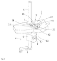
Fig.1 is a schematic drawing showing an elevating and unilateral locking linkage for a bottom mould according to the invention; -
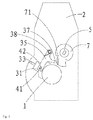
Fig.2 is top view of thefig.1 , wherein the bottom mould descends; -
Fig.3 is top view of thefig.2 when the bottom mould is positioned, wherein the bottom mould rises; - The present invention will be described hereinafter with reference to the accompanying drawings. It is to be noted, however, that the drawings are given only for illustrative purpose and therefore not to be considered as limiting of its scope, for the invention may admit to other equally effective embodiments.
-
Fig.1 generally shows the structure of the bottom mould elevating assembly and the positioning assembly, these assemblies are mounted on a bottle blowing machine for use. The other parts of the bottle blowing machine are not involved by the main technical points of the invention and are well known by one skilled in the art, and thus not shown in fig.s. The mechanism shown infig.1 comprises amachine frame 2, a bottom mould positioning assembly 3, a drivingassembly 4 for driving the elevating of the bottom mould. Generally the machine frame is provided with a mould blowing assembly (a commonly used mechanism, not illustrated fully). The mould blowing assembly comprises a left mould and a right mould which can be closed or opened, and a bottom mould slidably disposed on the machine frame in up-down direction. When the mould is closed, the left and right moulds engage with each other and the bottom mould draws close to the left and right moulds, such that the three moulds together enclose to provide a cavity. When the mould is opened, the three moulds are separated to open the cavity. - As shown in fig.s, the driving
assembly 4 comprises arotation shaft 5 rotatably disposed on themachine frame 2 around it's own axis, acam 6 fixedly connected with the lower portion of therotation shaft 5, and a power source for driving the rotation of therotation shaft 5, a first sliding groove 8 is opened on thecam 6. The drivingassembly 4 also comprises a swing arm 9 for connecting therotation shaft 5 with the power source. - The
bottom mould 1 is disposed on the upper end of an elevatingrod 12, and a slidingpart 13 slidable along the first guiding groove 8 is provided on the lower portion of the elevatingrod 12, as shown infig.1 . Thebottom mould 1, the elevatingrod 2 and the slidingpart 13 can be integrated as one piece. - In the course of rotation of the
rotation shaft 5, the first sliding groove 8 contacts and supports the slidingpart 13, with the support position of first sliding groove 8 rising or descending, , the slidingpart 13 moves in up-down direction under the guiding of the first sliding groove 8. Correspondingly, the elevatingrod 2 drives the elevating of thebottom mould 1. - In the preferable embodiment shown in
fig.1 , the axis of rotation of therotation shaft 5 is parallel to the direction of movement of the elevatingrod 12 relative to themachine frame 2. The guiding groove 8 inclinedly extends relative to the plane perpendicular to the axis of rotation. Herein, the term "inclinedly" means that the central axis of the first sliding groove 8 representing the extending direction of the guiding groove 8 is not in the same circumference of the cross-section of therotation shaft 5. The extending direction of the first sliding groove 8 is neither parallel to the axis of rotation of therotation shaft 5, nor vertical to the axis of rotation. In this case, in the course of rotation of therotation shaft 5, the slidingpart 13 slidably cooperating with the first sliding groove 8 moves in up-down direction under the guiding of the guidinggroove 4. -
Fig.s 2-3 illustrate more intuitively the configuration of the positioning assembly 3. - The positioning assembly 3 comprises a
rotation member 7 fixedly disposed on therotation shaft 5, aswing member 35 cooperating with therotation member 7 and a slidingblock 31 slidable in the horizontal direction. One end of theswing member 35 is rotatably connected with themachine frame 2, and the other end is connected with the slidingblock 31. - Specifically, the
rotation member 7 has a guidingsurface 71 thereon and aprojection 37 is formed on theswing member 35, in the course of rotation of therotation member 7, theprojection 37 slidably contacts with the guidingsurface 71. The guidingsurface 71 can be configured as an evolvent-shaped structure. The distance between the outer edge of the cross-section of the guidingsurface 71 along the line where the radius of the rotation shaft is and the shaft axis of therotation shaft 5 becomes bigger and bigger or smaller and smaller clockwise. Certainly, the guidingsurface 71 also can be configured as other curved configurations. The guidingsurface 71 is formed such that the distance between the shaft axis of therotation shaft 5 and the contact position of theprojection 37 with the guidingsurface 71 changes with the rotation of therotation member 7, thereby leading to the swinging of theswing member 35. - The positioning assembly 3 also comprises a
guide rail 33 disposed along the horizontal direction, and the slidingblock 31 is slidably disposed along theguide rail 33. - A
convex column 41 is formed on the slidingblock 31, and a second slidinggroove 42 is formed on theswing member 35, theconvex column 41 is slidably inserted into the second slidinggroove 42. The portion of theswing member 35 where the second slidinggroove 42 is opened forms a transmission fork configuration for driving the sliding of the slidingblock 31 on theguide rail 33. - Preferably, a
torsional spring 38 is arranged between theswing member 35 and themachine frame 2 for providing a restoring force for theswing member 35. Referring to the conversion fromfig.2 to fig.3 , therotation member 7 rotates anticlockwise, due to the guiding effect of the guidingsurface 71, theprojection 37 contacting with it moves towards the shaft axis of the rotation shaft 5 (namely, the axis of rotation of therotation shaft 5 relative to the machine frame 2), at this time, theswing member 35 rotates anticlockwise under the acting force of theswing member 35, and the transmission fork portion drives the slidingblock 31 to move along theguide rail 33 into the position shown infig.3 , that is to say, the slidingblock 31 is inserted between thebottom mould 1 and themachine frame 2 and contacts thebottom mould 1 to position thebottom mould 1. Again referring to the conversion fromfig.3 to fig.2 , therotation member 7 rotates clockwise, the contact position of the guidingsurface 71 with theprojection 37 is farther and farther from the shaft axis of therotation shaft 5, and thus theprojection 37 is pushed to move, in this course, theswing member 35 overcomes the acting force of thetorsional spring 38 to rotates clockwise, and drives the slidingblock 31 to move into the position shown infig.2 by the transmission fork portion, namely, the slidingblock 31 is detached from thebottom mould 1 and thebottom mould 1 is released. When the mould blowing assembly is in the mould closing state, thebottom mould 1 rises such that it is spaced apart from themachine frame 2, the slidingblock 31 is inserted between thebottom mould 1 and themachine frame 2 and contacts against thebottom mould 1 below thebottom mould 1. When the bottom blowing assembly is in the mould opening state, the power source drives therotation shaft 5 to rotate, and therotation shaft 5 drives the rotation of thecam 6 and therotation member 7. When therotation member 7 rotates, theprojection 37 slides along the guidingsurface 71 such that theswing member 35 swings, the slidingblock 31 is driven by the theswing member 35 to slide along theguide rail 33, then the positioning assembly 3 is opened and thecam 6 rotates with therotation shaft 5. The slidingpart 13 slides along the f irst sliding groove 8 such that the bottom mould descends and the mould opening is reached. - The above embodiment is described for illustrating the technical concept and features of the invention, the aim is intended to enable a person skilled in the art to appreciate the content of the invention and further implement it, and the protecting scope of the invention can not be limited hereby. Also, any equivalent variations or modifications made according to the spirit of the invention should be covered within the protecting scope of the invention.
Claims (9)
- An elevating and unilateral locking linkage for a bottom mould, mounted on a bottle blowing machine, the linkage comprising a bottom mould elevating assembly and a positioning assembly (3), the bottom mould elevating assembly comprising an elevating rod (12) movably disposed on a machine frame (2) of the bottle blowing machine in up-down direction, the bottom mould (1) being mounted on an upper end of the elevating rod (12), the elevating rod (12) being driven by a driving assembly(4) to move in up-down direction,
the driving assembly(4) comprising:a rotation shaft (5) rotatably disposed on the machine frame (2) around a first axis;a cam (6) fixedly connected on the rotation shaft (5), a first sliding groove (8) being opened on the cam (6);a sliding part (13) mounted on the elevating rod (12), the sliding part (13) being slidably inserted into the first sliding groove (8); anda power source for driving the rotation of the rotation shaft (5);in the course of rotation of the rotation shaft (5), the contact position of the first sliding groove (8) with the sliding part (13) rises or descends, the sliding part (13) moves in up-down direction under the guiding of the first sliding groove (8); andthe positioning assembly (3) comprising:a sliding block (31) slidably disposed on the machine frame (2);a swing member (35) swingably disposed on the machine frame (2) around a second axis, for driving the movement of the sliding block (31) during it's swinging; anda rotation member (7) fixedly disposed on the rotation shaft (5) for controlling the swinging of the swing member (35);wherein the linkage has at least two working positions, in the first working position , there is a certain distance between the bottom mould (1) and the machine frame (2), and sliding block (31) is inserted between the bottom mould (1) and the machine frame (2) and contacts against the bottom mould (1), in the second working position, the sliding block (31) is separated from the bottom mould (1) ,such that the bottom mould (1) moves towards the machine frame (2). - The linkage as claimed in claim 1, wherein the driving assembly (4) also comprises a swing arm (9) for connecting the rotation shaft (5) with the power source, the swing arm (9), the cam (6) and the sliding part (13) being located below the machine frame (2).
- The linkage as claimed in claim 2, wherein a first through-hole for the rotation shaft (5) extending through therein and a second through-hole for the elevating rod (12) extending through therein respectively are opened on the machine frame (2).
- The linkage as claimed in any of claims 1-3, wherein the rotation member (7), the swing member (35), the sliding block (31) and the bottom mould (1) are located above an upper surface of the machine frame (2).
- The linkage as claimed in claim 1, wherein the rotation member (7) has a guiding surface (71) thereon and a projection (37) is formed on the swing member (35), the projection (37) slidably contacting with the guiding surface (71), and the distance between the contact position of the projection (37) with the guiding surface (71) and the first axis changing with the rotation of the rotation member (7).
- The linkage as claimed in claim 1 or 5, wherein an elastic member is arranged between the swing member (35) and the machine frame (2) for providing a restoring force for the swing member (35).
- The linkage as claimed in claim 1, wherein a linear guide rail (33) is formed on the machine frame (2), the sliding block (31) being slidably disposed on the guide rail (33).
- The linkage as claimed in claim 1 or 7, wherein a convex column (41) is formed on the sliding block (31), a second sliding groove (42) is opened on the swing member (35) at a distance from the second axis, the convex column (41) being slidably inserted into the second sliding groove (42).
- The linkage as claimed in any of claims 1-3 and 5, wherein the firs axis is parallel to the second axis.
Applications Claiming Priority (2)
| Application Number | Priority Date | Filing Date | Title |
|---|---|---|---|
| CN201310088983.4A CN103171137B (en) | 2013-03-19 | 2013-03-19 | Bottom die lifting and single-side locking linkage mechanism |
| PCT/CN2013/074944 WO2014146325A1 (en) | 2013-03-19 | 2013-04-28 | Linkage mechanism between bottom die lifting and unilateral clamping |
Publications (3)
| Publication Number | Publication Date |
|---|---|
| EP2977170A1 true EP2977170A1 (en) | 2016-01-27 |
| EP2977170A4 EP2977170A4 (en) | 2016-10-26 |
| EP2977170B1 EP2977170B1 (en) | 2017-07-12 |
Family
ID=48631541
Family Applications (1)
| Application Number | Title | Priority Date | Filing Date |
|---|---|---|---|
| EP13879047.2A Active EP2977170B1 (en) | 2013-03-19 | 2013-04-28 | Linkage mechanism between bottom die lifting and unilateral clamping |
Country Status (3)
| Country | Link |
|---|---|
| EP (1) | EP2977170B1 (en) |
| CN (1) | CN103171137B (en) |
| WO (1) | WO2014146325A1 (en) |
Families Citing this family (4)
| Publication number | Priority date | Publication date | Assignee | Title |
|---|---|---|---|---|
| CN103171138B (en) * | 2013-03-19 | 2015-03-25 | 江苏新美星包装机械股份有限公司 | Bottom die single-side locking mechanism |
| CN110142948A (en) * | 2019-05-06 | 2019-08-20 | 广州达意隆包装机械股份有限公司 | A kind of bottle blowing machine side form and bed die linkage |
| CN110295996B (en) * | 2019-06-14 | 2022-02-11 | 郝凤成 | Swing arm cam type two-stroke straight shaft internal combustion engine |
| CN115923093B (en) * | 2022-11-16 | 2023-11-03 | 佛山市南海功成塑料有限公司 | Plastic bottle blow molding production equipment and plastic bottle blow molding method |
Family Cites Families (14)
| Publication number | Priority date | Publication date | Assignee | Title |
|---|---|---|---|---|
| GB1040882A (en) * | 1962-03-10 | 1966-09-01 | British United Shoe Machinery | Improvements in or relating to shoe upper conforming machines |
| FR2793722B1 (en) * | 1999-05-17 | 2001-08-03 | Sidel Sa | BLOWING MACHINE COMPRISING A CLOSING AND LOCKING MECHANISM COMBINED WITH A MOLDING UNIT |
| FR2841495B1 (en) * | 2002-06-27 | 2004-11-12 | Sidel Sa | DEVICE FOR MOLDING, BY BLOWING OR STRETCH-BLOWING, CONTAINERS OF THERMOPLASTIC MATERIAL |
| DE102007022638A1 (en) * | 2007-05-15 | 2008-11-20 | Sig Technology Ag | Device for blow molding containers |
| CN201325179Y (en) * | 2008-12-25 | 2009-10-14 | 解冬正 | Die opening and locking mechanism of bottle blowing machine |
| CN101502999B (en) * | 2009-03-16 | 2010-12-29 | 张家港市同大机械有限公司 | Matched mould locking mechanism of hollow plastic forming machine |
| CN201755911U (en) | 2010-08-05 | 2011-03-09 | 杨茂林 | Bottom die locking device of linear bottle blowing machine |
| DE102010039803A1 (en) * | 2010-08-26 | 2012-03-01 | Krones Aktiengesellschaft | blow |
| CN102205626A (en) * | 2011-01-11 | 2011-10-05 | 广州达意隆包装机械股份有限公司 | Striking device for elevating of mode locked shaft component |
| DE102011106572A1 (en) * | 2011-06-16 | 2012-12-20 | Krones Aktiengesellschaft | Blow molding machine with plain bearing swivel shafts |
| CN102765186B (en) * | 2012-07-14 | 2014-04-23 | 江苏新美星包装机械股份有限公司 | Die locking mechanism |
| CN102862285B (en) * | 2012-10-17 | 2014-11-05 | 广州达意隆包装机械股份有限公司 | Linked connection rod mechanism of bottle blowing machine |
| CN102962989B (en) * | 2012-11-22 | 2015-07-29 | 广州达意隆包装机械股份有限公司 | The link gear of bottle blowing machine limit mould and bed die |
| CN203157121U (en) * | 2013-03-19 | 2013-08-28 | 江苏新美星包装机械股份有限公司 | Bottom die lifting and single-side locking linkage mechanism |
-
2013
- 2013-03-19 CN CN201310088983.4A patent/CN103171137B/en active Active
- 2013-04-28 WO PCT/CN2013/074944 patent/WO2014146325A1/en active Application Filing
- 2013-04-28 EP EP13879047.2A patent/EP2977170B1/en active Active
Also Published As
| Publication number | Publication date |
|---|---|
| EP2977170A4 (en) | 2016-10-26 |
| WO2014146325A1 (en) | 2014-09-25 |
| CN103171137A (en) | 2013-06-26 |
| CN103171137B (en) | 2015-02-11 |
| EP2977170B1 (en) | 2017-07-12 |
Similar Documents
| Publication | Publication Date | Title |
|---|---|---|
| EP2977173A1 (en) | Linkage mechanism between lifting and bilateral positioning of bottom die | |
| EP2977171B1 (en) | Bottle blowing machine | |
| EP2977175A1 (en) | Bottle blowing machine having bottom die lifting clamping mechanism | |
| EP2977174B1 (en) | Linkage mechanism between uniaxial die opening and closing and bottom die lifting | |
| EP2977176A1 (en) | Linkage mechanism between uniaxial die opening and closing and bottom die positioning | |
| EP2977179A1 (en) | Bottle blowing machine | |
| EP2977170B1 (en) | Linkage mechanism between bottom die lifting and unilateral clamping | |
| EP2977169B1 (en) | Blow mould with linkage mechanism between single shaft die opening and closing and bottom die clamping | |
| EP2977181A1 (en) | Bottom die lifting mechanism | |
| EP2977180B1 (en) | Link mechanism for opening and closing die and positioning bottom die by single shaft | |
| JP4029302B1 (en) | Safety equipment for press equipment | |
| EP2977177A1 (en) | Bilateral clamping mechanism for bottom die | |
| JP2014034161A (en) | Vertical injection molding machine | |
| EP2977178A1 (en) | Bottom die single-side locking mechanism | |
| CN106409621B (en) | The supplementary module of control and protective switching device | |
| CN105399021B (en) | Die turning-over device | |
| CN210759164U (en) | Connecting rod type linkage mechanism for bottle blowing machine mould frame | |
| CN215127234U (en) | Pressure cooker with supportable cooker cover | |
| CN210147129U (en) | Lower protection device for saw blade | |
| CN203969094U (en) | For the elasticity door-opening mechanism on tea carding machine | |
| KR20110052040A (en) | Apparatus up-down bin cover of tripper | |
| CN115503218B (en) | Single-die-opening bottle blowing die frame | |
| CN203393391U (en) | Movable plate opening mechanism of flat knitting machine | |
| JP6282953B2 (en) | Raw cover holding device | |
| CN203145787U (en) | Mobile door window protective device |
Legal Events
| Date | Code | Title | Description |
|---|---|---|---|
| PUAI | Public reference made under article 153(3) epc to a published international application that has entered the european phase |
Free format text: ORIGINAL CODE: 0009012 |
|
| 17P | Request for examination filed |
Effective date: 20150519 |
|
| AK | Designated contracting states |
Kind code of ref document: A1 Designated state(s): AL AT BE BG CH CY CZ DE DK EE ES FI FR GB GR HR HU IE IS IT LI LT LU LV MC MK MT NL NO PL PT RO RS SE SI SK SM TR |
|
| AX | Request for extension of the european patent |
Extension state: BA ME |
|
| RAP3 | Party data changed (applicant data changed or rights of an application transferred) |
Owner name: JIANGSU NEWAMSTAR PACKAGING MACHINERY CO., LTD |
|
| DAX | Request for extension of the european patent (deleted) | ||
| A4 | Supplementary search report drawn up and despatched |
Effective date: 20160923 |
|
| RIC1 | Information provided on ipc code assigned before grant |
Ipc: B29C 49/48 20060101ALN20160919BHEP Ipc: B29C 49/56 20060101AFI20160919BHEP Ipc: B29C 49/36 20060101ALN20160919BHEP Ipc: B29L 22/00 20060101ALI20160919BHEP Ipc: B29C 49/64 20060101ALN20160919BHEP |
|
| REG | Reference to a national code |
Ref country code: DE Ref legal event code: R079 Ref document number: 602013023593 Country of ref document: DE Free format text: PREVIOUS MAIN CLASS: B29C0045640000 Ipc: B29C0049560000 |
|
| RIC1 | Information provided on ipc code assigned before grant |
Ipc: B29C 49/56 20060101AFI20170208BHEP Ipc: B29C 49/48 20060101ALN20170208BHEP Ipc: B29C 49/36 20060101ALN20170208BHEP Ipc: B29C 49/64 20060101ALN20170208BHEP Ipc: B29L 22/00 20060101ALI20170208BHEP |
|
| GRAP | Despatch of communication of intention to grant a patent |
Free format text: ORIGINAL CODE: EPIDOSNIGR1 |
|
| STAA | Information on the status of an ep patent application or granted ep patent |
Free format text: STATUS: GRANT OF PATENT IS INTENDED |
|
| INTG | Intention to grant announced |
Effective date: 20170329 |
|
| GRAS | Grant fee paid |
Free format text: ORIGINAL CODE: EPIDOSNIGR3 |
|
| GRAA | (expected) grant |
Free format text: ORIGINAL CODE: 0009210 |
|
| STAA | Information on the status of an ep patent application or granted ep patent |
Free format text: STATUS: THE PATENT HAS BEEN GRANTED |
|
| AK | Designated contracting states |
Kind code of ref document: B1 Designated state(s): AL AT BE BG CH CY CZ DE DK EE ES FI FR GB GR HR HU IE IS IT LI LT LU LV MC MK MT NL NO PL PT RO RS SE SI SK SM TR |
|
| REG | Reference to a national code |
Ref country code: GB Ref legal event code: FG4D |
|
| REG | Reference to a national code |
Ref country code: CH Ref legal event code: EP |
|
| REG | Reference to a national code |
Ref country code: AT Ref legal event code: REF Ref document number: 907921 Country of ref document: AT Kind code of ref document: T Effective date: 20170715 |
|
| REG | Reference to a national code |
Ref country code: IE Ref legal event code: FG4D |
|
| REG | Reference to a national code |
Ref country code: DE Ref legal event code: R096 Ref document number: 602013023593 Country of ref document: DE |
|
| REG | Reference to a national code |
Ref country code: NL Ref legal event code: MP Effective date: 20170712 |
|
| REG | Reference to a national code |
Ref country code: LT Ref legal event code: MG4D |
|
| REG | Reference to a national code |
Ref country code: AT Ref legal event code: MK05 Ref document number: 907921 Country of ref document: AT Kind code of ref document: T Effective date: 20170712 |
|
| PG25 | Lapsed in a contracting state [announced via postgrant information from national office to epo] |
Ref country code: AT Free format text: LAPSE BECAUSE OF FAILURE TO SUBMIT A TRANSLATION OF THE DESCRIPTION OR TO PAY THE FEE WITHIN THE PRESCRIBED TIME-LIMIT Effective date: 20170712 Ref country code: LT Free format text: LAPSE BECAUSE OF FAILURE TO SUBMIT A TRANSLATION OF THE DESCRIPTION OR TO PAY THE FEE WITHIN THE PRESCRIBED TIME-LIMIT Effective date: 20170712 Ref country code: SE Free format text: LAPSE BECAUSE OF FAILURE TO SUBMIT A TRANSLATION OF THE DESCRIPTION OR TO PAY THE FEE WITHIN THE PRESCRIBED TIME-LIMIT Effective date: 20170712 Ref country code: HR Free format text: LAPSE BECAUSE OF FAILURE TO SUBMIT A TRANSLATION OF THE DESCRIPTION OR TO PAY THE FEE WITHIN THE PRESCRIBED TIME-LIMIT Effective date: 20170712 Ref country code: FI Free format text: LAPSE BECAUSE OF FAILURE TO SUBMIT A TRANSLATION OF THE DESCRIPTION OR TO PAY THE FEE WITHIN THE PRESCRIBED TIME-LIMIT Effective date: 20170712 Ref country code: NL Free format text: LAPSE BECAUSE OF FAILURE TO SUBMIT A TRANSLATION OF THE DESCRIPTION OR TO PAY THE FEE WITHIN THE PRESCRIBED TIME-LIMIT Effective date: 20170712 Ref country code: NO Free format text: LAPSE BECAUSE OF FAILURE TO SUBMIT A TRANSLATION OF THE DESCRIPTION OR TO PAY THE FEE WITHIN THE PRESCRIBED TIME-LIMIT Effective date: 20171012 |
|
| PG25 | Lapsed in a contracting state [announced via postgrant information from national office to epo] |
Ref country code: BG Free format text: LAPSE BECAUSE OF FAILURE TO SUBMIT A TRANSLATION OF THE DESCRIPTION OR TO PAY THE FEE WITHIN THE PRESCRIBED TIME-LIMIT Effective date: 20171012 Ref country code: PL Free format text: LAPSE BECAUSE OF FAILURE TO SUBMIT A TRANSLATION OF THE DESCRIPTION OR TO PAY THE FEE WITHIN THE PRESCRIBED TIME-LIMIT Effective date: 20170712 Ref country code: RS Free format text: LAPSE BECAUSE OF FAILURE TO SUBMIT A TRANSLATION OF THE DESCRIPTION OR TO PAY THE FEE WITHIN THE PRESCRIBED TIME-LIMIT Effective date: 20170712 Ref country code: IS Free format text: LAPSE BECAUSE OF FAILURE TO SUBMIT A TRANSLATION OF THE DESCRIPTION OR TO PAY THE FEE WITHIN THE PRESCRIBED TIME-LIMIT Effective date: 20171112 Ref country code: LV Free format text: LAPSE BECAUSE OF FAILURE TO SUBMIT A TRANSLATION OF THE DESCRIPTION OR TO PAY THE FEE WITHIN THE PRESCRIBED TIME-LIMIT Effective date: 20170712 Ref country code: GR Free format text: LAPSE BECAUSE OF FAILURE TO SUBMIT A TRANSLATION OF THE DESCRIPTION OR TO PAY THE FEE WITHIN THE PRESCRIBED TIME-LIMIT Effective date: 20171013 Ref country code: ES Free format text: LAPSE BECAUSE OF FAILURE TO SUBMIT A TRANSLATION OF THE DESCRIPTION OR TO PAY THE FEE WITHIN THE PRESCRIBED TIME-LIMIT Effective date: 20170712 |
|
| REG | Reference to a national code |
Ref country code: FR Ref legal event code: PLFP Year of fee payment: 6 |
|
| REG | Reference to a national code |
Ref country code: DE Ref legal event code: R097 Ref document number: 602013023593 Country of ref document: DE |
|
| PG25 | Lapsed in a contracting state [announced via postgrant information from national office to epo] |
Ref country code: DK Free format text: LAPSE BECAUSE OF FAILURE TO SUBMIT A TRANSLATION OF THE DESCRIPTION OR TO PAY THE FEE WITHIN THE PRESCRIBED TIME-LIMIT Effective date: 20170712 Ref country code: RO Free format text: LAPSE BECAUSE OF FAILURE TO SUBMIT A TRANSLATION OF THE DESCRIPTION OR TO PAY THE FEE WITHIN THE PRESCRIBED TIME-LIMIT Effective date: 20170712 Ref country code: CZ Free format text: LAPSE BECAUSE OF FAILURE TO SUBMIT A TRANSLATION OF THE DESCRIPTION OR TO PAY THE FEE WITHIN THE PRESCRIBED TIME-LIMIT Effective date: 20170712 |
|
| PLBE | No opposition filed within time limit |
Free format text: ORIGINAL CODE: 0009261 |
|
| STAA | Information on the status of an ep patent application or granted ep patent |
Free format text: STATUS: NO OPPOSITION FILED WITHIN TIME LIMIT |
|
| PG25 | Lapsed in a contracting state [announced via postgrant information from national office to epo] |
Ref country code: SM Free format text: LAPSE BECAUSE OF FAILURE TO SUBMIT A TRANSLATION OF THE DESCRIPTION OR TO PAY THE FEE WITHIN THE PRESCRIBED TIME-LIMIT Effective date: 20170712 Ref country code: EE Free format text: LAPSE BECAUSE OF FAILURE TO SUBMIT A TRANSLATION OF THE DESCRIPTION OR TO PAY THE FEE WITHIN THE PRESCRIBED TIME-LIMIT Effective date: 20170712 Ref country code: SK Free format text: LAPSE BECAUSE OF FAILURE TO SUBMIT A TRANSLATION OF THE DESCRIPTION OR TO PAY THE FEE WITHIN THE PRESCRIBED TIME-LIMIT Effective date: 20170712 |
|
| 26N | No opposition filed |
Effective date: 20180413 |
|
| PG25 | Lapsed in a contracting state [announced via postgrant information from national office to epo] |
Ref country code: SI Free format text: LAPSE BECAUSE OF FAILURE TO SUBMIT A TRANSLATION OF THE DESCRIPTION OR TO PAY THE FEE WITHIN THE PRESCRIBED TIME-LIMIT Effective date: 20170712 |
|
| PG25 | Lapsed in a contracting state [announced via postgrant information from national office to epo] |
Ref country code: MC Free format text: LAPSE BECAUSE OF FAILURE TO SUBMIT A TRANSLATION OF THE DESCRIPTION OR TO PAY THE FEE WITHIN THE PRESCRIBED TIME-LIMIT Effective date: 20170712 |
|
| REG | Reference to a national code |
Ref country code: CH Ref legal event code: PL |
|
| REG | Reference to a national code |
Ref country code: BE Ref legal event code: MM Effective date: 20180430 |
|
| GBPC | Gb: european patent ceased through non-payment of renewal fee |
Effective date: 20180428 |
|
| REG | Reference to a national code |
Ref country code: IE Ref legal event code: MM4A |
|
| PG25 | Lapsed in a contracting state [announced via postgrant information from national office to epo] |
Ref country code: LU Free format text: LAPSE BECAUSE OF NON-PAYMENT OF DUE FEES Effective date: 20180428 |
|
| PG25 | Lapsed in a contracting state [announced via postgrant information from national office to epo] |
Ref country code: CH Free format text: LAPSE BECAUSE OF NON-PAYMENT OF DUE FEES Effective date: 20180430 Ref country code: BE Free format text: LAPSE BECAUSE OF NON-PAYMENT OF DUE FEES Effective date: 20180430 Ref country code: LI Free format text: LAPSE BECAUSE OF NON-PAYMENT OF DUE FEES Effective date: 20180430 Ref country code: GB Free format text: LAPSE BECAUSE OF NON-PAYMENT OF DUE FEES Effective date: 20180428 |
|
| PG25 | Lapsed in a contracting state [announced via postgrant information from national office to epo] |
Ref country code: IE Free format text: LAPSE BECAUSE OF NON-PAYMENT OF DUE FEES Effective date: 20180428 |
|
| PGFP | Annual fee paid to national office [announced via postgrant information from national office to epo] |
Ref country code: TR Payment date: 20190422 Year of fee payment: 7 |
|
| PG25 | Lapsed in a contracting state [announced via postgrant information from national office to epo] |
Ref country code: MT Free format text: LAPSE BECAUSE OF NON-PAYMENT OF DUE FEES Effective date: 20180428 |
|
| PG25 | Lapsed in a contracting state [announced via postgrant information from national office to epo] |
Ref country code: PT Free format text: LAPSE BECAUSE OF FAILURE TO SUBMIT A TRANSLATION OF THE DESCRIPTION OR TO PAY THE FEE WITHIN THE PRESCRIBED TIME-LIMIT Effective date: 20170712 |
|
| PG25 | Lapsed in a contracting state [announced via postgrant information from national office to epo] |
Ref country code: MK Free format text: LAPSE BECAUSE OF NON-PAYMENT OF DUE FEES Effective date: 20170712 Ref country code: CY Free format text: LAPSE BECAUSE OF FAILURE TO SUBMIT A TRANSLATION OF THE DESCRIPTION OR TO PAY THE FEE WITHIN THE PRESCRIBED TIME-LIMIT Effective date: 20170712 Ref country code: HU Free format text: LAPSE BECAUSE OF FAILURE TO SUBMIT A TRANSLATION OF THE DESCRIPTION OR TO PAY THE FEE WITHIN THE PRESCRIBED TIME-LIMIT; INVALID AB INITIO Effective date: 20130428 |
|
| PG25 | Lapsed in a contracting state [announced via postgrant information from national office to epo] |
Ref country code: AL Free format text: LAPSE BECAUSE OF FAILURE TO SUBMIT A TRANSLATION OF THE DESCRIPTION OR TO PAY THE FEE WITHIN THE PRESCRIBED TIME-LIMIT Effective date: 20170712 |
|
| PG25 | Lapsed in a contracting state [announced via postgrant information from national office to epo] |
Ref country code: TR Free format text: LAPSE BECAUSE OF NON-PAYMENT OF DUE FEES Effective date: 20200428 |
|
| P01 | Opt-out of the competence of the unified patent court (upc) registered |
Effective date: 20230519 |
|
| PGFP | Annual fee paid to national office [announced via postgrant information from national office to epo] |
Ref country code: IT Payment date: 20230421 Year of fee payment: 11 Ref country code: FR Payment date: 20230421 Year of fee payment: 11 Ref country code: DE Payment date: 20230419 Year of fee payment: 11 |