EP2977144A2 - Machining tool including a pivoting machining arm and a method of using the same - Google Patents
Machining tool including a pivoting machining arm and a method of using the same Download PDFInfo
- Publication number
- EP2977144A2 EP2977144A2 EP15177839.6A EP15177839A EP2977144A2 EP 2977144 A2 EP2977144 A2 EP 2977144A2 EP 15177839 A EP15177839 A EP 15177839A EP 2977144 A2 EP2977144 A2 EP 2977144A2
- Authority
- EP
- European Patent Office
- Prior art keywords
- machining
- arm
- machining arm
- pivotable
- angle
- Prior art date
- Legal status (The legal status is an assumption and is not a legal conclusion. Google has not performed a legal analysis and makes no representation as to the accuracy of the status listed.)
- Granted
Links
Images


Classifications
-
- B—PERFORMING OPERATIONS; TRANSPORTING
- B24—GRINDING; POLISHING
- B24B—MACHINES, DEVICES, OR PROCESSES FOR GRINDING OR POLISHING; DRESSING OR CONDITIONING OF ABRADING SURFACES; FEEDING OF GRINDING, POLISHING, OR LAPPING AGENTS
- B24B21/00—Machines or devices using grinding or polishing belts; Accessories therefor
- B24B21/006—Machines or devices using grinding or polishing belts; Accessories therefor for special purposes, e.g. for television tubes, car bumpers
-
- B—PERFORMING OPERATIONS; TRANSPORTING
- B24—GRINDING; POLISHING
- B24B—MACHINES, DEVICES, OR PROCESSES FOR GRINDING OR POLISHING; DRESSING OR CONDITIONING OF ABRADING SURFACES; FEEDING OF GRINDING, POLISHING, OR LAPPING AGENTS
- B24B21/00—Machines or devices using grinding or polishing belts; Accessories therefor
-
- B—PERFORMING OPERATIONS; TRANSPORTING
- B24—GRINDING; POLISHING
- B24B—MACHINES, DEVICES, OR PROCESSES FOR GRINDING OR POLISHING; DRESSING OR CONDITIONING OF ABRADING SURFACES; FEEDING OF GRINDING, POLISHING, OR LAPPING AGENTS
- B24B21/00—Machines or devices using grinding or polishing belts; Accessories therefor
- B24B21/18—Accessories
- B24B21/20—Accessories for controlling or adjusting the tracking or the tension of the grinding belt
-
- B—PERFORMING OPERATIONS; TRANSPORTING
- B24—GRINDING; POLISHING
- B24B—MACHINES, DEVICES, OR PROCESSES FOR GRINDING OR POLISHING; DRESSING OR CONDITIONING OF ABRADING SURFACES; FEEDING OF GRINDING, POLISHING, OR LAPPING AGENTS
- B24B23/00—Portable grinding machines, e.g. hand-guided; Accessories therefor
- B24B23/06—Portable grinding machines, e.g. hand-guided; Accessories therefor with abrasive belts, e.g. with endless travelling belts; Accessories therefor
-
- B—PERFORMING OPERATIONS; TRANSPORTING
- B24—GRINDING; POLISHING
- B24B—MACHINES, DEVICES, OR PROCESSES FOR GRINDING OR POLISHING; DRESSING OR CONDITIONING OF ABRADING SURFACES; FEEDING OF GRINDING, POLISHING, OR LAPPING AGENTS
- B24B41/00—Component parts such as frames, beds, carriages, headstocks
- B24B41/002—Grinding heads
Definitions
- the present disclosure is generally related to machining and boring tools and, more specifically, a machining tool including a pivoting machining arm and a method of using the same.
- Gas turbine engines such as those used to power modern commercial aircraft or in industrial applications, include a compressor for pressurizing a supply of air, a combustor for burning a hydrocarbon fuel in the presence of the pressurized air, and a turbine for extracting energy from the resultant combustion gases.
- the compressor, combustor and turbine are disposed about a central engine axis with the compressor disposed axially upstream of the combustor and the turbine disposed axially downstream of the combustor.
- the inner diameter of a rotor from the gas turbine engine requires machining to remove raised materials formed during manufacturing. Typically, this is done using a solid turning tool that moves through the centre of the rotor and then positions its cutting edge between the bores, up to the surface needing to be machined. Certain rotor geometries do not allow a solid turning tool to reach deep enough to the inner diameter area requiring the removal of the raised materials.
- a machining tool including a pivoting machining arm.
- the machining arm including a first arm section and a second arm section, a proximate end, a distal end, and a machining arm longitudinal axis.
- at least a portion of the machining arm is configured to pivot such that an angle is formed between the distal end and the machining arm longitudinal axis.
- the angle between the distal end and the machining arm longitudinal axis includes an angle between approximately 0° and approximately 180°.
- the machining tool 10 further includes a belt disposed around the machining arm.
- the belt includes an abrasive coating suitable disposed thereon.
- the machining tool further includes a first motor operably coupled to the machining arm.
- the machining arm further includes a power pulley located adjacent to the first arm section, and at least one idler pulley located adjacent to the second arm section.
- the machining tool further includes a second motor (not shown) operably coupled to the second arm section.
- a controller (not shown) is in communication with the second motor.
- a method for removing raised surfaces from a structure with a machining tool including a motor, a pivotable machining arm operably coupled to the motor, and a belt disposed around the pivotable machining arm includes the step of placing the pivotable machining arm in a first orientation.
- placing the pivotable machining arm in a first orientation includes placing the pivotable machining arm such that the angle between the distal end and the machining arm longitudinal axis comprises an angle less than approximately 180°.
- the method further includes the step of inserting the pivotable machining arm adjacent to a desired location.
- the method further includes the step of determining whether the belt is in a desired location relative to a raised surface. If it is determined that the belt is in a desired location relative to the raised surface; then the method proceeds to the step of operating the first motor to rotate the belt around the pivotable machining arm.
- placing the pivotable machining arm in a second orientation includes placing the pivotable machining arm such that the angle between the distal end and the machining arm longitudinal axis includes an angle between approximately 0° and approximately 180°.
- the method proceeds to the step of placing the belt in contact with the raised surface.
- the method further includes the step of removing the pivotable machining arm.
- removing the pivotable machining arm includes placing the pivotable machining arm in a third orientation such that the angle between the distal end and the machining arm longitudinal axis includes an angle less than approximately 180°.
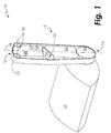
- FIG. 1 illustrates a machining tool 10 in a first configuration.
- the machining tool 10 includes a machining arm 12, including a proximate end 14, a distal end 16, and a machining arm longitudinal axis 18. At least a portion of the machining arm 12 is configured to pivot such that an angle 20 is formed between the distal end 16 and the machining arm longitudinal axis 18. In one embodiment, the angle 20 between the distal end 16 and the machining arm longitudinal axis 18 includes an angle between approximately 0° and approximately 180°. In the example shown, the machining arm 12 is in an extended configuration having an angle 20 of approximately 180° between the distal end 16 and the machining arm longitudinal axis 18.
- the machining tool 10 further includes a belt 22 disposed around the machining arm 12. In one embodiment, the belt 22 includes an abrasive coating suitable for boring through metal.
- the machining tool 10 further includes a first motor 23 operably coupled to the machining arm 12. The first motor 23 is configured to operate the machining arm 12 to rotate the belt 22.
- the machining arm 12 includes a hinge component 24 located between a first arm section 26 and a second arm section 28.
- the second arm section 28 is configured to pivot around a pivot point 25 causing the second arm section 28 to pivot in a counterclockwise direction; thus, causing the distal end 16 to form the angle 20 with the machining arm longitudinal axis 18 (as shown in FIG. 2 ). It will be appreciated that the second arm section 28 may pivot in a clockwise direction.
- the machining arm 12 further includes a power pulley 30 located adjacent to the first arm section 26, and at least one idler pulley 32 located adjacent to the second arm section 28.
- the machining tool 10 further includes a second motor (not shown) operably coupled to the second arm section 28.
- the second motor is configured to pivot the second arm section 28 around the pivot point 25; thus, pivoting the distal end 16 of the pivoting machining arm 12.
- a controller (not shown) is in communication with the second motor. The controller is configured to transmit a signal to the second motor, wherein the signal is indicative of the user's desired position of the second arm section 28 of the pivoting machining arm 12.
- the user may operate the controller to send a signal to the second motor to rotate until the distal end 16 of the machining arm 12 is at the desired position.
- a method 100 for removing raised surfaces 42 from a structure 40 using the machining tool 10 described herein includes the step 102 of placing the machining arm 12 in a first orientation.
- placing the machining arm 12 in a first orientation includes placing the machining arm 12 such that the angle between the distal end 16 and the machining arm longitudinal axis 18 includes an angle 20 less than approximately 180°.
- the second arm section 28 pivots around the pivot point 25 causing the distal end 16 to form the angle 20 with the machining arm longitudinal axis 18 that is less than approximately 180°. Placing the machining arm 12 in a collapsed orientation allows the machining arm 12 to easily enter the structure 40 to reach deep areas for tooling purposes.
- the method 100 further includes the step 104 of inserting the machining arm 12 adjacent to a desired location. After placing the machining arm 12 in a first orientation the machining arm 12 may now be placed in a desired location of the structure 40, for example deep areas of an inner diameter of a rotor assembly.
- the method 100 further includes the step 106 of determining whether the belt 22 is in a desired location relative to a raised surface 42. If it is determined that the belt 22 is in a desired location relative to the raised surface 42, then the method 100 proceeds to step 108 of operating the first motor 23 to rotate the belt 22 around the machining arm 12.
- step 110 of placing the machining arm 12 in a second orientation such that the belt 22 is in a desired location relative to the raised surface 22.
- placing the machining arm 12 in a second orientation includes placing the machining arm 12 such that the angle 20 between the distal end 16 and the machining arm longitudinal axis 18 includes an angle 20 between approximately 0° - 180°.
- the second arm section 28 is pivoted around the pivot point 25 causing the distal end 16 to form the angle 20 with the machining arm longitudinal axis 18 until the second arm section 28 is placed in the desired position relative to the raised surface 42.
- the angle 20 is approximately 180°.
- step 112 of placing the belt 22 in contact with the raised surface 42 The belt 22 is placed in contact with the raised materials 42, and as the belt 22 circulates, the abrasive coating disposed thereon removes the raised materials 42 from the structure 40.
- the method 100 further includes the step 114 of removing the machining arm 12.
- removing the machining arm 12 includes placing the machining arm 12 in a third orientation such that the angle between the distal end 16 and the machining arm longitudinal axis 18 includes an angle 20 less than approximately 180°.
- the machining arm 12 may reach the inner diameter of a rotor 40 to remove raised areas of material 42 from the inner diameter of the rotor 40; thus reducing the need for more expensive tooling machines. It will also be appreciated that the machining tool 10 may be used in numerous applications where typical machining tools cannot reach surfaces of a particular part.
Landscapes
- Engineering & Computer Science (AREA)
- Mechanical Engineering (AREA)
- Finish Polishing, Edge Sharpening, And Grinding By Specific Grinding Devices (AREA)
- Drilling And Boring (AREA)
Abstract
Description
- The present disclosure is generally related to machining and boring tools and, more specifically, a machining tool including a pivoting machining arm and a method of using the same.
- Gas turbine engines, such as those used to power modern commercial aircraft or in industrial applications, include a compressor for pressurizing a supply of air, a combustor for burning a hydrocarbon fuel in the presence of the pressurized air, and a turbine for extracting energy from the resultant combustion gases. Generally, the compressor, combustor and turbine are disposed about a central engine axis with the compressor disposed axially upstream of the combustor and the turbine disposed axially downstream of the combustor.
- Generally, the inner diameter of a rotor from the gas turbine engine requires machining to remove raised materials formed during manufacturing. Typically, this is done using a solid turning tool that moves through the centre of the rotor and then positions its cutting edge between the bores, up to the surface needing to be machined. Certain rotor geometries do not allow a solid turning tool to reach deep enough to the inner diameter area requiring the removal of the raised materials.
- Improvements in machining tools are therefore needed in the art.
- In one aspect, a machining tool including a pivoting machining arm is provided. The machining arm including a first arm section and a second arm section, a proximate end, a distal end, and a machining arm longitudinal axis. In one embodiment, at least a portion of the machining arm is configured to pivot such that an angle is formed between the distal end and the machining arm longitudinal axis. In one embodiment, the angle between the distal end and the machining arm longitudinal axis includes an angle between approximately 0° and approximately 180°. The machining tool 10 further includes a belt disposed around the machining arm. In one embodiment, the belt includes an abrasive coating suitable disposed thereon. The machining tool further includes a first motor operably coupled to the machining arm.
- In one embodiment, the machining arm further includes a power pulley located adjacent to the first arm section, and at least one idler pulley located adjacent to the second arm section.
- In one embodiment, the machining tool further includes a second motor (not shown) operably coupled to the second arm section. In one embodiment, a controller (not shown) is in communication with the second motor.
- In one aspect a method for removing raised surfaces from a structure with a machining tool including a motor, a pivotable machining arm operably coupled to the motor, and a belt disposed around the pivotable machining arm is provided. The method includes the step of placing the pivotable machining arm in a first orientation. In one embodiment, placing the pivotable machining arm in a first orientation includes placing the pivotable machining arm such that the angle between the distal end and the machining arm longitudinal axis comprises an angle less than approximately 180°.
- The method further includes the step of inserting the pivotable machining arm adjacent to a desired location. The method further includes the step of determining whether the belt is in a desired location relative to a raised surface.
If it is determined that the belt is in a desired location relative to the raised surface; then the method proceeds to the step of operating the first motor to rotate the belt around the pivotable machining arm. - If it is determined that the belt is not in a desired location relative to the raised surface; then, the method proceeds to the step of placing the pivotable machining arm in a second orientation. In one embodiment, placing the pivotable machining arm in a second orientation includes placing the pivotable machining arm such that the angle between the distal end and the machining arm longitudinal axis includes an angle between approximately 0° and approximately 180°.
- The method proceeds to the step of placing the belt in contact with the raised surface. The method further includes the step of removing the pivotable machining arm. In one embodiment, removing the pivotable machining arm includes placing the pivotable machining arm in a third orientation such that the angle between the distal end and the machining arm longitudinal axis includes an angle less than approximately 180°.
- Other embodiments are also disclosed.
- The embodiments and other features, advantages and disclosures contained herein, and the manner of attaining them, will become apparent and the present disclosure will be better understood by reference to the following description of various exemplary embodiments of the present disclosure taken in conjunction with the accompanying drawings, wherein:
-
FIG. 1 is a schematic diagram of a machining tool of the present disclosure in a first configuration; -
FIG. 2 is a schematic diagram of a machining tool of the present disclosure in a second configuration; -
FIG. 3 . is a schematic flow diagram of a method for operating the machining tool to remove raised surfaces from a structure; and -
FIG. 4 is a schematic diagram of a machining tool of the present disclosure in use with a gas turbine engine rotor. - For the purposes of promoting an understanding of the principles of the present disclosure, reference will now be made to the embodiments illustrated in the drawings, and specific language will be used to describe the same. It will nevertheless be understood that no limitation of the scope of this disclosure is thereby intended.
-
FIG. 1 illustrates a machining tool 10 in a first configuration. The machining tool 10 includes amachining arm 12, including aproximate end 14, adistal end 16, and a machining armlongitudinal axis 18. At least a portion of themachining arm 12 is configured to pivot such that anangle 20 is formed between thedistal end 16 and the machining armlongitudinal axis 18. In one embodiment, theangle 20 between thedistal end 16 and the machining armlongitudinal axis 18 includes an angle between approximately 0° and approximately 180°. In the example shown, themachining arm 12 is in an extended configuration having anangle 20 of approximately 180° between thedistal end 16 and the machining armlongitudinal axis 18. The machining tool 10 further includes abelt 22 disposed around themachining arm 12. In one embodiment, thebelt 22 includes an abrasive coating suitable for boring through metal. The machining tool 10 further includes afirst motor 23 operably coupled to themachining arm 12. Thefirst motor 23 is configured to operate themachining arm 12 to rotate thebelt 22. - In one embodiment, the
machining arm 12 includes ahinge component 24 located between afirst arm section 26 and asecond arm section 28. Thesecond arm section 28 is configured to pivot around apivot point 25 causing thesecond arm section 28 to pivot in a counterclockwise direction; thus, causing thedistal end 16 to form theangle 20 with the machining arm longitudinal axis 18 (as shown inFIG. 2 ). It will be appreciated that thesecond arm section 28 may pivot in a clockwise direction. Themachining arm 12 further includes apower pulley 30 located adjacent to thefirst arm section 26, and at least oneidler pulley 32 located adjacent to thesecond arm section 28. - In one embodiment, the machining tool 10 further includes a second motor (not shown) operably coupled to the
second arm section 28. The second motor is configured to pivot thesecond arm section 28 around thepivot point 25; thus, pivoting thedistal end 16 of the pivotingmachining arm 12. In one embodiment, a controller (not shown) is in communication with the second motor. The controller is configured to transmit a signal to the second motor, wherein the signal is indicative of the user's desired position of thesecond arm section 28 of thepivoting machining arm 12. For example, if the user prefers thedistal end 16 of thepivoting machining arm 12 to be at a 30° angle from the machining armlongitudinal axis 18, the user may operate the controller to send a signal to the second motor to rotate until thedistal end 16 of themachining arm 12 is at the desired position. - Referring to
FIGs. 3 - 4 , amethod 100 for removing raisedsurfaces 42 from astructure 40 using the machining tool 10 described herein is provided. Themethod 100 includes the step 102 of placing themachining arm 12 in a first orientation. In one embodiment, placing themachining arm 12 in a first orientation includes placing themachining arm 12 such that the angle between thedistal end 16 and the machining armlongitudinal axis 18 includes anangle 20 less than approximately 180°. For example, to prepare the machining tool 10 to enter astructure 40 to remove the raisedsurfaces 42, thesecond arm section 28 pivots around thepivot point 25 causing thedistal end 16 to form theangle 20 with the machining armlongitudinal axis 18 that is less than approximately 180°. Placing themachining arm 12 in a collapsed orientation allows themachining arm 12 to easily enter thestructure 40 to reach deep areas for tooling purposes. - The
method 100 further includes thestep 104 of inserting themachining arm 12 adjacent to a desired location. After placing themachining arm 12 in a first orientation themachining arm 12 may now be placed in a desired location of thestructure 40, for example deep areas of an inner diameter of a rotor assembly. - The
method 100 further includes thestep 106 of determining whether thebelt 22 is in a desired location relative to a raisedsurface 42. If it is determined that thebelt 22 is in a desired location relative to the raisedsurface 42, then themethod 100 proceeds to step 108 of operating thefirst motor 23 to rotate thebelt 22 around themachining arm 12. - If it is determined that the
belt 22 is not in a desired location relative to the raisedsurface 42, then themethod 100 proceeds to step 110 of placing themachining arm 12 in a second orientation such that thebelt 22 is in a desired location relative to the raisedsurface 22. In one embodiment, placing themachining arm 12 in a second orientation includes placing themachining arm 12 such that theangle 20 between thedistal end 16 and the machining armlongitudinal axis 18 includes anangle 20 between approximately 0° - 180°. For example, if thesecond arm section 28 is not properly aligned to remove the raisedsurface 42, thesecond arm section 28 is pivoted around thepivot point 25 causing thedistal end 16 to form theangle 20 with the machining armlongitudinal axis 18 until thesecond arm section 28 is placed in the desired position relative to the raisedsurface 42. In the example shown inFIG. 4 , theangle 20 is approximately 180°. - Once the
machining arm 12 is place in the desired position relative to the raisedsurface 42, themethod 100 proceeds to step 112 of placing thebelt 22 in contact with the raisedsurface 42. Thebelt 22 is placed in contact with the raisedmaterials 42, and as thebelt 22 circulates, the abrasive coating disposed thereon removes the raisedmaterials 42 from thestructure 40. - The
method 100 further includes thestep 114 of removing themachining arm 12. In one embodiment, removing themachining arm 12 includes placing themachining arm 12 in a third orientation such that the angle between thedistal end 16 and the machining armlongitudinal axis 18 includes anangle 20 less than approximately 180°. - It will be appreciated that the
machining arm 12 may reach the inner diameter of arotor 40 to remove raised areas ofmaterial 42 from the inner diameter of therotor 40; thus reducing the need for more expensive tooling machines. It will also be appreciated that the machining tool 10 may be used in numerous applications where typical machining tools cannot reach surfaces of a particular part. - While the invention has been illustrated and described in detail in the drawings and foregoing description, the same is to be considered as illustrative and not restrictive in character, it being understood that only certain embodiments have been shown and described and that all changes and modifications that come within the spirit of the invention are desired to be protected.
Claims (15)
- A machining tool comprising:a machining arm including a first arm section and a second arm section, a proximate end, a distal end, and a machining arm longitudinal axis;a belt disposed around the machining arm; anda first motor operably coupled to the machining arm;wherein at least a portion of the machining arm is configured to pivot such that an angle is formed between the distal end and the machining arm longitudinal axis.
- The machining tool of claim 1, wherein the machining arm further comprises:a hinge component located between the first arm section and the second arm section;a power pulley located adjacent to the first arm section; andat least one idler pulley located adjacent to the second arm section.
- The machining tool of claim 2, wherein the first motor is operably coupled to the power pulley.
- The machining tool of claim 2, further comprising a second motor operably coupled to the hinge component.
- The machining tool of claim 4, further comprising a controller in communication with the second motor.
- The machining tool of claim 1, wherein the angle between the distal end and the machining arm longitudinal axis comprises an angle between approximately 0° and approximately 180°.
- The machining tool of claim 1, wherein the belt includes an abrasive coating.
- A method for removing raised surfaces from a structure with a machining tool including a motor, a pivotable machining arm operably coupled to the motor, and a belt disposed around the pivotable machining arm, the method comprising the steps;
placing the pivotable machining arm in a first orientation;
inserting the pivotable machining arm adjacent to a desired location; determining whether the belt is in a desired position relative to the raised surface;
operating the motor to rotate the belt around the pivotable machining arm; and
placing the belt in contact with the raised surface. - The method of claim 8, wherein the pivotable machining arm comprises a proximate end, a distal end, and a machining arm longitudinal axis; wherein at least a portion of the pivotable machining arm is configured to pivot such that an angle is formed between the distal end and the machining arm longitudinal axis.
- The method of claim 9, wherein the angle between the distal end and the machining arm longitudinal axis comprises an angle between approximately 0° and approximately 180°.
- The method of claim 9, wherein placing the pivotable machining arm in a first orientation comprises placing the pivotable machining arm such that the angle between the distal end and the machining arm longitudinal axis comprises an angle less than approximately 180°.
- The method of claim 9, further comprising placing the pivotable machining arm in a second orientation if it is determined that the belt is not in the desired position relative to the raised surface.
- The method of claim 12, wherein placing the pivotable machining arm in a second orientation comprises placing the pivotable machining arm such that the angle between the distal end and the machining arm longitudinal axis comprises an angle between approximately 0° and approximately 180°.
- The method of claim 9, further comprising removing the pivotable machining arm from the desired location.
- The method of claim 14, wherein placing the pivotable machining arm in a third orientation comprises placing the pivotable machining arm such that the angle between the distal end and the machining arm longitudinal axis comprises an angle less than approximately 180°.
Applications Claiming Priority (1)
| Application Number | Priority Date | Filing Date | Title |
|---|---|---|---|
| US201462027578P | 2014-07-22 | 2014-07-22 |
Publications (3)
| Publication Number | Publication Date |
|---|---|
| EP2977144A2 true EP2977144A2 (en) | 2016-01-27 |
| EP2977144A3 EP2977144A3 (en) | 2016-03-02 |
| EP2977144B1 EP2977144B1 (en) | 2018-02-28 |
Family
ID=54010820
Family Applications (1)
| Application Number | Title | Priority Date | Filing Date |
|---|---|---|---|
| EP15177839.6A Not-in-force EP2977144B1 (en) | 2014-07-22 | 2015-07-22 | Machining tool including a pivoting machining arm and a method of using the same |
Country Status (2)
| Country | Link |
|---|---|
| US (1) | US9757837B2 (en) |
| EP (1) | EP2977144B1 (en) |
Family Cites Families (11)
| Publication number | Priority date | Publication date | Assignee | Title |
|---|---|---|---|---|
| US2401670A (en) * | 1944-11-28 | 1946-06-04 | Frank F Spetz | Portable grinder |
| US3093170A (en) * | 1960-03-04 | 1963-06-11 | Julius A Thayer | Portable log debarking machine |
| US3566549A (en) * | 1969-01-21 | 1971-03-02 | James A Britton | Flexible all purpose drill attachment |
| US3823513A (en) * | 1973-10-12 | 1974-07-16 | Dynabrade | Miniature belt grinder |
| US4509296A (en) * | 1982-03-22 | 1985-04-09 | Rasmussen Aaron P | Radial belt grinder |
| US5628678A (en) * | 1996-05-03 | 1997-05-13 | Tridico; Frank | Shaft sanding device |
| US6503128B1 (en) | 2000-06-07 | 2003-01-07 | William R. Deware | Contour sanding attachment and method |
| US6648737B2 (en) * | 2000-06-07 | 2003-11-18 | William R. Deware | Contour sanding apparatus and kit |
| JP2006123059A (en) | 2004-10-28 | 2006-05-18 | Mitsubishi Heavy Ind Ltd | Polishing device, polishing robot using the same, and polishing method |
| US9366145B2 (en) | 2012-08-24 | 2016-06-14 | United Technologies Corporation | Turbine engine rotor assembly |
| US20140141700A1 (en) * | 2012-11-16 | 2014-05-22 | Radius Master Machinery PTY Limited | Belt grinder |
-
2015
- 2015-07-07 US US14/793,498 patent/US9757837B2/en not_active Expired - Fee Related
- 2015-07-22 EP EP15177839.6A patent/EP2977144B1/en not_active Not-in-force
Non-Patent Citations (1)
| Title |
|---|
| None |
Also Published As
| Publication number | Publication date |
|---|---|
| US9757837B2 (en) | 2017-09-12 |
| US20160023320A1 (en) | 2016-01-28 |
| EP2977144A3 (en) | 2016-03-02 |
| EP2977144B1 (en) | 2018-02-28 |
Similar Documents
| Publication | Publication Date | Title |
|---|---|---|
| EP2947276A1 (en) | Grooved blade outer air seals | |
| EP2105245B1 (en) | Method for repairing an airfoil | |
| EP2113634B1 (en) | Method of repairing a gas turbine engine case with replaced flange using cold metal transfer | |
| KR20140138877A (en) | Apparatus and method for servicing turbomachinery components in-situ | |
| US10316672B2 (en) | Airfoils with low-angle holes and methods for drilling same | |
| EP2859976A1 (en) | Machining tool and method for abradable coating pattern | |
| US10047765B2 (en) | Bushing for a variable stator vane and method of making same | |
| EP3366412A1 (en) | A workpiece with a spatial weld joint plane arrangement and a method for forming the workpiece | |
| EP3034809B1 (en) | Gas turbine engine component with abrasive surface formed by electrical discharge machining | |
| KR20170054571A (en) | Template for forming cooling passages in a turbine engine component | |
| US11773749B2 (en) | Method and system for nozzle ring repair | |
| EP3071813B1 (en) | Axisymmetric offset of three-dimensional contoured endwalls | |
| EP2977144B1 (en) | Machining tool including a pivoting machining arm and a method of using the same | |
| US10132176B2 (en) | Split airfoil cluster and method therefor | |
| EP2008759B1 (en) | Tool alignment fixture and method | |
| CA3015255C (en) | Device and method for re-contouring a gas turbine blade | |
| US20200254546A1 (en) | Device for holding one or more electrode(s) for electrical discharge machining, and method of obtaining same | |
| EP4159370B1 (en) | Tool and repair method for removing a thermal barrier coating | |
| US20150354388A1 (en) | Turbine shroud milling | |
| EP2749375B1 (en) | Method of reinforcing combustor aperture and related combustor | |
| EP2943656B1 (en) | A method of establishing a boundary for a material improvement process on an airfoil, and airfoil for a gas turbine engine. | |
| US10821575B2 (en) | Clamp assembly and method | |
| US20130224028A1 (en) | Component blending tool assembly | |
| EP2248929A1 (en) | Method of electrical discharge surface repair of a variable vane trunnion | |
| JP2008126397A (en) | Manufacturing method for stainless steel exhaust system component |
Legal Events
| Date | Code | Title | Description |
|---|---|---|---|
| PUAI | Public reference made under article 153(3) epc to a published international application that has entered the european phase |
Free format text: ORIGINAL CODE: 0009012 |
|
| AK | Designated contracting states |
Kind code of ref document: A2 Designated state(s): AL AT BE BG CH CY CZ DE DK EE ES FI FR GB GR HR HU IE IS IT LI LT LU LV MC MK MT NL NO PL PT RO RS SE SI SK SM TR |
|
| AX | Request for extension of the european patent |
Extension state: BA ME |
|
| PUAL | Search report despatched |
Free format text: ORIGINAL CODE: 0009013 |
|
| AK | Designated contracting states |
Kind code of ref document: A3 Designated state(s): AL AT BE BG CH CY CZ DE DK EE ES FI FR GB GR HR HU IE IS IT LI LT LU LV MC MK MT NL NO PL PT RO RS SE SI SK SM TR |
|
| AX | Request for extension of the european patent |
Extension state: BA ME |
|
| RIC1 | Information provided on ipc code assigned before grant |
Ipc: B24B 21/00 20060101AFI20160128BHEP Ipc: B24B 23/06 20060101ALI20160128BHEP |
|
| 17P | Request for examination filed |
Effective date: 20160901 |
|
| RBV | Designated contracting states (corrected) |
Designated state(s): AL AT BE BG CH CY CZ DE DK EE ES FI FR GB GR HR HU IE IS IT LI LT LU LV MC MK MT NL NO PL PT RO RS SE SI SK SM TR |
|
| RAP1 | Party data changed (applicant data changed or rights of an application transferred) |
Owner name: UNITED TECHNOLOGIES CORPORATION |
|
| GRAP | Despatch of communication of intention to grant a patent |
Free format text: ORIGINAL CODE: EPIDOSNIGR1 |
|
| STAA | Information on the status of an ep patent application or granted ep patent |
Free format text: STATUS: GRANT OF PATENT IS INTENDED |
|
| INTG | Intention to grant announced |
Effective date: 20170105 |
|
| GRAA | (expected) grant |
Free format text: ORIGINAL CODE: 0009210 |
|
| GRAS | Grant fee paid |
Free format text: ORIGINAL CODE: EPIDOSNIGR3 |
|
| STAA | Information on the status of an ep patent application or granted ep patent |
Free format text: STATUS: THE PATENT HAS BEEN GRANTED |
|
| AK | Designated contracting states |
Kind code of ref document: B1 Designated state(s): AL AT BE BG CH CY CZ DE DK EE ES FI FR GB GR HR HU IE IS IT LI LT LU LV MC MK MT NL NO PL PT RO RS SE SI SK SM TR |
|
| REG | Reference to a national code |
Ref country code: GB Ref legal event code: FG4D Ref country code: CH Ref legal event code: EP |
|
| REG | Reference to a national code |
Ref country code: AT Ref legal event code: REF Ref document number: 973601 Country of ref document: AT Kind code of ref document: T Effective date: 20180315 |
|
| REG | Reference to a national code |
Ref country code: IE Ref legal event code: FG4D |
|
| REG | Reference to a national code |
Ref country code: DE Ref legal event code: R096 Ref document number: 602015008262 Country of ref document: DE |
|
| REG | Reference to a national code |
Ref country code: FR Ref legal event code: PLFP Year of fee payment: 4 |
|
| REG | Reference to a national code |
Ref country code: NL Ref legal event code: MP Effective date: 20180228 |
|
| REG | Reference to a national code |
Ref country code: LT Ref legal event code: MG4D |
|
| REG | Reference to a national code |
Ref country code: AT Ref legal event code: MK05 Ref document number: 973601 Country of ref document: AT Kind code of ref document: T Effective date: 20180228 |
|
| PG25 | Lapsed in a contracting state [announced via postgrant information from national office to epo] |
Ref country code: ES Free format text: LAPSE BECAUSE OF FAILURE TO SUBMIT A TRANSLATION OF THE DESCRIPTION OR TO PAY THE FEE WITHIN THE PRESCRIBED TIME-LIMIT Effective date: 20180228 Ref country code: NL Free format text: LAPSE BECAUSE OF FAILURE TO SUBMIT A TRANSLATION OF THE DESCRIPTION OR TO PAY THE FEE WITHIN THE PRESCRIBED TIME-LIMIT Effective date: 20180228 Ref country code: LT Free format text: LAPSE BECAUSE OF FAILURE TO SUBMIT A TRANSLATION OF THE DESCRIPTION OR TO PAY THE FEE WITHIN THE PRESCRIBED TIME-LIMIT Effective date: 20180228 Ref country code: CY Free format text: LAPSE BECAUSE OF FAILURE TO SUBMIT A TRANSLATION OF THE DESCRIPTION OR TO PAY THE FEE WITHIN THE PRESCRIBED TIME-LIMIT Effective date: 20180228 Ref country code: NO Free format text: LAPSE BECAUSE OF FAILURE TO SUBMIT A TRANSLATION OF THE DESCRIPTION OR TO PAY THE FEE WITHIN THE PRESCRIBED TIME-LIMIT Effective date: 20180528 Ref country code: HR Free format text: LAPSE BECAUSE OF FAILURE TO SUBMIT A TRANSLATION OF THE DESCRIPTION OR TO PAY THE FEE WITHIN THE PRESCRIBED TIME-LIMIT Effective date: 20180228 Ref country code: FI Free format text: LAPSE BECAUSE OF FAILURE TO SUBMIT A TRANSLATION OF THE DESCRIPTION OR TO PAY THE FEE WITHIN THE PRESCRIBED TIME-LIMIT Effective date: 20180228 |
|
| PG25 | Lapsed in a contracting state [announced via postgrant information from national office to epo] |
Ref country code: RS Free format text: LAPSE BECAUSE OF FAILURE TO SUBMIT A TRANSLATION OF THE DESCRIPTION OR TO PAY THE FEE WITHIN THE PRESCRIBED TIME-LIMIT Effective date: 20180228 Ref country code: LV Free format text: LAPSE BECAUSE OF FAILURE TO SUBMIT A TRANSLATION OF THE DESCRIPTION OR TO PAY THE FEE WITHIN THE PRESCRIBED TIME-LIMIT Effective date: 20180228 Ref country code: GR Free format text: LAPSE BECAUSE OF FAILURE TO SUBMIT A TRANSLATION OF THE DESCRIPTION OR TO PAY THE FEE WITHIN THE PRESCRIBED TIME-LIMIT Effective date: 20180529 Ref country code: AT Free format text: LAPSE BECAUSE OF FAILURE TO SUBMIT A TRANSLATION OF THE DESCRIPTION OR TO PAY THE FEE WITHIN THE PRESCRIBED TIME-LIMIT Effective date: 20180228 Ref country code: BG Free format text: LAPSE BECAUSE OF FAILURE TO SUBMIT A TRANSLATION OF THE DESCRIPTION OR TO PAY THE FEE WITHIN THE PRESCRIBED TIME-LIMIT Effective date: 20180528 Ref country code: SE Free format text: LAPSE BECAUSE OF FAILURE TO SUBMIT A TRANSLATION OF THE DESCRIPTION OR TO PAY THE FEE WITHIN THE PRESCRIBED TIME-LIMIT Effective date: 20180228 |
|
| PG25 | Lapsed in a contracting state [announced via postgrant information from national office to epo] |
Ref country code: RO Free format text: LAPSE BECAUSE OF FAILURE TO SUBMIT A TRANSLATION OF THE DESCRIPTION OR TO PAY THE FEE WITHIN THE PRESCRIBED TIME-LIMIT Effective date: 20180228 Ref country code: PL Free format text: LAPSE BECAUSE OF FAILURE TO SUBMIT A TRANSLATION OF THE DESCRIPTION OR TO PAY THE FEE WITHIN THE PRESCRIBED TIME-LIMIT Effective date: 20180228 Ref country code: AL Free format text: LAPSE BECAUSE OF FAILURE TO SUBMIT A TRANSLATION OF THE DESCRIPTION OR TO PAY THE FEE WITHIN THE PRESCRIBED TIME-LIMIT Effective date: 20180228 Ref country code: IT Free format text: LAPSE BECAUSE OF FAILURE TO SUBMIT A TRANSLATION OF THE DESCRIPTION OR TO PAY THE FEE WITHIN THE PRESCRIBED TIME-LIMIT Effective date: 20180228 Ref country code: EE Free format text: LAPSE BECAUSE OF FAILURE TO SUBMIT A TRANSLATION OF THE DESCRIPTION OR TO PAY THE FEE WITHIN THE PRESCRIBED TIME-LIMIT Effective date: 20180228 |
|
| REG | Reference to a national code |
Ref country code: DE Ref legal event code: R097 Ref document number: 602015008262 Country of ref document: DE |
|
| PG25 | Lapsed in a contracting state [announced via postgrant information from national office to epo] |
Ref country code: DK Free format text: LAPSE BECAUSE OF FAILURE TO SUBMIT A TRANSLATION OF THE DESCRIPTION OR TO PAY THE FEE WITHIN THE PRESCRIBED TIME-LIMIT Effective date: 20180228 Ref country code: SM Free format text: LAPSE BECAUSE OF FAILURE TO SUBMIT A TRANSLATION OF THE DESCRIPTION OR TO PAY THE FEE WITHIN THE PRESCRIBED TIME-LIMIT Effective date: 20180228 Ref country code: SK Free format text: LAPSE BECAUSE OF FAILURE TO SUBMIT A TRANSLATION OF THE DESCRIPTION OR TO PAY THE FEE WITHIN THE PRESCRIBED TIME-LIMIT Effective date: 20180228 Ref country code: CZ Free format text: LAPSE BECAUSE OF FAILURE TO SUBMIT A TRANSLATION OF THE DESCRIPTION OR TO PAY THE FEE WITHIN THE PRESCRIBED TIME-LIMIT Effective date: 20180228 |
|
| PLBE | No opposition filed within time limit |
Free format text: ORIGINAL CODE: 0009261 |
|
| STAA | Information on the status of an ep patent application or granted ep patent |
Free format text: STATUS: NO OPPOSITION FILED WITHIN TIME LIMIT |
|
| 26N | No opposition filed |
Effective date: 20181129 |
|
| PG25 | Lapsed in a contracting state [announced via postgrant information from national office to epo] |
Ref country code: SI Free format text: LAPSE BECAUSE OF FAILURE TO SUBMIT A TRANSLATION OF THE DESCRIPTION OR TO PAY THE FEE WITHIN THE PRESCRIBED TIME-LIMIT Effective date: 20180228 |
|
| REG | Reference to a national code |
Ref country code: CH Ref legal event code: PL |
|
| PG25 | Lapsed in a contracting state [announced via postgrant information from national office to epo] |
Ref country code: LU Free format text: LAPSE BECAUSE OF NON-PAYMENT OF DUE FEES Effective date: 20180722 Ref country code: MC Free format text: LAPSE BECAUSE OF FAILURE TO SUBMIT A TRANSLATION OF THE DESCRIPTION OR TO PAY THE FEE WITHIN THE PRESCRIBED TIME-LIMIT Effective date: 20180228 |
|
| REG | Reference to a national code |
Ref country code: BE Ref legal event code: MM Effective date: 20180731 |
|
| REG | Reference to a national code |
Ref country code: IE Ref legal event code: MM4A |
|
| PG25 | Lapsed in a contracting state [announced via postgrant information from national office to epo] |
Ref country code: IE Free format text: LAPSE BECAUSE OF NON-PAYMENT OF DUE FEES Effective date: 20180722 Ref country code: CH Free format text: LAPSE BECAUSE OF NON-PAYMENT OF DUE FEES Effective date: 20180731 Ref country code: LI Free format text: LAPSE BECAUSE OF NON-PAYMENT OF DUE FEES Effective date: 20180731 |
|
| PG25 | Lapsed in a contracting state [announced via postgrant information from national office to epo] |
Ref country code: BE Free format text: LAPSE BECAUSE OF NON-PAYMENT OF DUE FEES Effective date: 20180731 |
|
| PG25 | Lapsed in a contracting state [announced via postgrant information from national office to epo] |
Ref country code: MT Free format text: LAPSE BECAUSE OF NON-PAYMENT OF DUE FEES Effective date: 20180722 |
|
| PG25 | Lapsed in a contracting state [announced via postgrant information from national office to epo] |
Ref country code: TR Free format text: LAPSE BECAUSE OF FAILURE TO SUBMIT A TRANSLATION OF THE DESCRIPTION OR TO PAY THE FEE WITHIN THE PRESCRIBED TIME-LIMIT Effective date: 20180228 |
|
| PG25 | Lapsed in a contracting state [announced via postgrant information from national office to epo] |
Ref country code: PT Free format text: LAPSE BECAUSE OF FAILURE TO SUBMIT A TRANSLATION OF THE DESCRIPTION OR TO PAY THE FEE WITHIN THE PRESCRIBED TIME-LIMIT Effective date: 20180228 |
|
| PG25 | Lapsed in a contracting state [announced via postgrant information from national office to epo] |
Ref country code: HU Free format text: LAPSE BECAUSE OF FAILURE TO SUBMIT A TRANSLATION OF THE DESCRIPTION OR TO PAY THE FEE WITHIN THE PRESCRIBED TIME-LIMIT; INVALID AB INITIO Effective date: 20150722 Ref country code: MK Free format text: LAPSE BECAUSE OF NON-PAYMENT OF DUE FEES Effective date: 20180228 |
|
| PG25 | Lapsed in a contracting state [announced via postgrant information from national office to epo] |
Ref country code: IS Free format text: LAPSE BECAUSE OF FAILURE TO SUBMIT A TRANSLATION OF THE DESCRIPTION OR TO PAY THE FEE WITHIN THE PRESCRIBED TIME-LIMIT Effective date: 20180628 |
|
| REG | Reference to a national code |
Ref country code: DE Ref legal event code: R081 Ref document number: 602015008262 Country of ref document: DE Owner name: RAYTHEON TECHNOLOGIES CORPORATION (N.D.GES.D.S, US Free format text: FORMER OWNER: UNITED TECHNOLOGIES CORPORATION, FARMINGTON, CONN., US |
|
| P01 | Opt-out of the competence of the unified patent court (upc) registered |
Effective date: 20230520 |
|
| PGFP | Annual fee paid to national office [announced via postgrant information from national office to epo] |
Ref country code: GB Payment date: 20240620 Year of fee payment: 10 |
|
| PGFP | Annual fee paid to national office [announced via postgrant information from national office to epo] |
Ref country code: FR Payment date: 20240619 Year of fee payment: 10 |
|
| PGFP | Annual fee paid to national office [announced via postgrant information from national office to epo] |
Ref country code: DE Payment date: 20240619 Year of fee payment: 10 |
|
| REG | Reference to a national code |
Ref country code: DE Ref legal event code: R119 Ref document number: 602015008262 Country of ref document: DE |
|
| GBPC | Gb: european patent ceased through non-payment of renewal fee |
Effective date: 20250722 |
|
| PG25 | Lapsed in a contracting state [announced via postgrant information from national office to epo] |
Ref country code: GB Free format text: LAPSE BECAUSE OF NON-PAYMENT OF DUE FEES Effective date: 20250722 |
|
| PG25 | Lapsed in a contracting state [announced via postgrant information from national office to epo] |
Ref country code: DE Free format text: LAPSE BECAUSE OF NON-PAYMENT OF DUE FEES Effective date: 20260203 |
|
| PG25 | Lapsed in a contracting state [announced via postgrant information from national office to epo] |
Ref country code: FR Free format text: LAPSE BECAUSE OF NON-PAYMENT OF DUE FEES Effective date: 20250731 |