EP2976553B1 - A joystick control for a change speed gearbox - Google Patents
A joystick control for a change speed gearbox Download PDFInfo
- Publication number
- EP2976553B1 EP2976553B1 EP14710903.7A EP14710903A EP2976553B1 EP 2976553 B1 EP2976553 B1 EP 2976553B1 EP 14710903 A EP14710903 A EP 14710903A EP 2976553 B1 EP2976553 B1 EP 2976553B1
- Authority
- EP
- European Patent Office
- Prior art keywords
- operating lever
- actuating members
- axle
- joystick control
- actuating
- Prior art date
- Legal status (The legal status is an assumption and is not a legal conclusion. Google has not performed a legal analysis and makes no representation as to the accuracy of the status listed.)
- Active
Links
Images


Classifications
-
- F—MECHANICAL ENGINEERING; LIGHTING; HEATING; WEAPONS; BLASTING
- F16—ENGINEERING ELEMENTS AND UNITS; GENERAL MEASURES FOR PRODUCING AND MAINTAINING EFFECTIVE FUNCTIONING OF MACHINES OR INSTALLATIONS; THERMAL INSULATION IN GENERAL
- F16H—GEARING
- F16H59/00—Control inputs to control units of change-speed- or reversing-gearings for conveying rotary motion
- F16H59/02—Selector apparatus
- F16H59/04—Ratio selector apparatus
- F16H59/042—Ratio selector apparatus comprising a final actuating mechanism
-
- F—MECHANICAL ENGINEERING; LIGHTING; HEATING; WEAPONS; BLASTING
- F16—ENGINEERING ELEMENTS AND UNITS; GENERAL MEASURES FOR PRODUCING AND MAINTAINING EFFECTIVE FUNCTIONING OF MACHINES OR INSTALLATIONS; THERMAL INSULATION IN GENERAL
- F16H—GEARING
- F16H61/00—Control functions within control units of change-speed- or reversing-gearings for conveying rotary motion ; Control of exclusively fluid gearing, friction gearing, gearings with endless flexible members or other particular types of gearing
- F16H61/26—Generation or transmission of movements for final actuating mechanisms
- F16H61/36—Generation or transmission of movements for final actuating mechanisms with at least one movement being transmitted by a cable
-
- F—MECHANICAL ENGINEERING; LIGHTING; HEATING; WEAPONS; BLASTING
- F16—ENGINEERING ELEMENTS AND UNITS; GENERAL MEASURES FOR PRODUCING AND MAINTAINING EFFECTIVE FUNCTIONING OF MACHINES OR INSTALLATIONS; THERMAL INSULATION IN GENERAL
- F16H—GEARING
- F16H63/00—Control outputs from the control unit to change-speed- or reversing-gearings for conveying rotary motion or to other devices than the final output mechanism
- F16H63/02—Final output mechanisms therefor; Actuating means for the final output mechanisms
- F16H63/30—Constructional features of the final output mechanisms
- F16H63/38—Detents
-
- F—MECHANICAL ENGINEERING; LIGHTING; HEATING; WEAPONS; BLASTING
- F16—ENGINEERING ELEMENTS AND UNITS; GENERAL MEASURES FOR PRODUCING AND MAINTAINING EFFECTIVE FUNCTIONING OF MACHINES OR INSTALLATIONS; THERMAL INSULATION IN GENERAL
- F16H—GEARING
- F16H59/00—Control inputs to control units of change-speed- or reversing-gearings for conveying rotary motion
- F16H59/02—Selector apparatus
- F16H2059/026—Details or special features of the selector casing or lever support
-
- F—MECHANICAL ENGINEERING; LIGHTING; HEATING; WEAPONS; BLASTING
- F16—ENGINEERING ELEMENTS AND UNITS; GENERAL MEASURES FOR PRODUCING AND MAINTAINING EFFECTIVE FUNCTIONING OF MACHINES OR INSTALLATIONS; THERMAL INSULATION IN GENERAL
- F16H—GEARING
- F16H59/00—Control inputs to control units of change-speed- or reversing-gearings for conveying rotary motion
- F16H59/02—Selector apparatus
- F16H2059/026—Details or special features of the selector casing or lever support
- F16H2059/0273—Cardan or gimbal type joints for supporting the lever
-
- F—MECHANICAL ENGINEERING; LIGHTING; HEATING; WEAPONS; BLASTING
- F16—ENGINEERING ELEMENTS AND UNITS; GENERAL MEASURES FOR PRODUCING AND MAINTAINING EFFECTIVE FUNCTIONING OF MACHINES OR INSTALLATIONS; THERMAL INSULATION IN GENERAL
- F16H—GEARING
- F16H63/00—Control outputs from the control unit to change-speed- or reversing-gearings for conveying rotary motion or to other devices than the final output mechanism
- F16H63/02—Final output mechanisms therefor; Actuating means for the final output mechanisms
- F16H63/30—Constructional features of the final output mechanisms
- F16H63/34—Locking or disabling mechanisms
- F16H63/36—Interlocking devices
Definitions
- the present invention relates to a joystick control for a change speed gearbox
- a joystick control for a change speed gearbox comprising a support body, an axle rotatably supported by the body, an operating lever connected to the axle by a pivot pin having an axis perpendicular to that of the axle such that the operating lever is rotatable about the axis of the axle and is pivotable relative to the axle about the axis of the pivot pin, two actuating members rotatably supported by the axle and arranged one on each side of the operating lever, each actuating member being connectible to a respective Bowden cable to extend and retract the cable in response to rotation of the actuating member about the axle, and mating formations on the operating lever and the actuating members operative to engage the operating lever selectively for rotation with one or the other of the actuating members in dependence upon the direction in which the operating lever is pivoted relative to the axle about the pivot pin.
- Such a joystick which will herein be referred to as a joystick control of the type described initially, is disclosed in WO2011/157558 , relevant parts of which are reproduced below.
- the present invention seeks to provide an improvement of joystick control of the type described initially to reduce free play in the operating lever.
- a joystick control of the type described initially wherein resiliently biased detents are provided between the support body and the actuating members or the operating lever to resist rotation of the operating lever away from at least one defined stable position.
- the actuating members are formed or fitted with cams each having at least one depression, the cams being engaged by resiliently biased cam followers mounted on the support body.
- the cam followers in some embodiments, have rollers that roll on the surfaces of the cams as the actuating members are rotated.
- notches are provided in the sides of the actuating members for receiving a shaft of the operating lever and a spring may furthermore be provided to urge the operating lever to engage in the notch of one of the actuating members.
- an interlock device may be provided between the two actuating members to prevent movement of each actuating member relative to the support body when the other actuating member is not in a neutral position.
- the interlock device may suitably comprise a locking pin slidably mounted in a through bore in a part of the support body disposed between the two actuating members, the opposite ends of the pin being receivable in holes in the actuating members, the holes and the pin being such that in the neutral positions of both actuating members the pin is biased towards a central position in which the ends of the pin engage partially within the holes of both actuating members but do not prevent rotation of either actuating member and when either member is rotated the pin is ejected from the bore in that member and engaged further in the hole of the other member to prevent rotation of the other member relative to the support body.
- FIGS. 1 to 4 show a joystick control of the type described initially. These figures are not of embodiments of the invention but will be described first to enable the later described embodiments of the invention to be understood more clearly.
- the joystick control 10 as most clearly shown in Figure 4 , comprises a main support body 12 formed with pillar blocks 14 and 16 within which an axle 18 is journalled on bearing bushes 20.
- the support body 12 is formed in two symmetrical halves that are joined to one another by rolled steel pins 22.
- the pins 22 may be replaced by rivets, screws or bolts and serve only to hold the two halves of the support body 12 together.
- An operating lever 24 is connected to the axle 18 by means of a pivot pin 26.
- the operating lever 24 has a shaft 24a that is moved in the same way as the gear stick of a conventional H-gate gearbox, with a fork 24b at one end that straddles the axle 18 and receives the pin 26 which passes through a hole 18a in the axle 18 extending at right angles to the rotational axis of the axle 18.
- the shaft 24a can be pivoted about the pin 26 relative to the axle 20 in the plane containing the axes of the axle 18 and the shaft 24a but rotates with the axle 18 in the orthogonal plane.
- Each actuating member 30 has a sector-shaped part 32 centred on a bearing 34 through which the axle 18 passes.
- Each actuating member 30 also has an extension arm 36 having a hole 38 at its end to receive a pin 40 by means of which the arm 36 is connected to the end of the inner cable 42 of a Bowden cable 44 of which the outer sheath is anchored to the support body 12 (see Figure 1 ).
- the radially outer surfaces of the actuating members 30 are formed with notches 50 that can receive the shaft 24a of the operating lever 24.
- Each notch is large enough to fully accommodate the shaft 24a so that when the shaft 24a rests within the notch of one actuating member, it lies totally outside the notch of the other actuating member.
- the Bowden cable acts directly on two selectors of the gearbox.
- One of the Bowden cables moves a selector for engaging the first and second speeds and the other acts on a different selector used for engaging the third and fourth speeds.
- the joystick control is shown in Figures 1 to 3 with the operating lever 24 in the neutral position.
- the two notches 50 of the two actuating members are in line with one another and the operating lever 24 can be pivoted about the pin 26 to rest wholly within either notch 50.
- a spring 52 is used to bias the operating lever to the left as viewed in Figure 2 , to engage within the notch of the actuating member 30 for selecting the first and second speeds.
- the axle 18 may be formed of PPS (polyphenylene sulfide) polymer, the bearing bushes 20 of POM (polyoximethylene) omopolymer, and the operating lever 24 and the actuating members 30 of a glass fibre reinforced nylon such as PA66 35GF (polyamide with 35% glass fibre).
- PPS polyphenylene sulfide
- POM polyoximethylene
- PA66 35GF polyamide with 35% glass fibre
- cams 160 are secured to the lower edge as viewed of each of the actuating members 130.
- the cams 160 can be formed as part of the actuating members 130.
- a cam follower module 170 with two roller followers 172 is mounted within the support body 112 and held in place by one of the roller steel pins 122.
- roller followers 172 The interaction between the roller followers 172 and the cams 160 is best shown in the section of Figure 6 .
- Each cam has a central depression 162 that is aligned with the respective spring biased follower roller 172 when the actuating member 130 is in its neutral position.
- the roller follower 172 acts as a ball catch, or a spring biased detent, to resist rotation of the actuating lever away from the neutral position.
- the outer flanks 164 of the cams 160 push the operating lever towards one or other of its end positions, once enough force has been applied to the operating lever to move it out of its neutral position against the action of the roller follower 172.
- the cams 160 in this way provide positive location of the operating lever 124 in the neutral position and in its end positions, significantly improving the feel of the joystick control 110 and rendering it more positive.
- a further improvement of the joystick of the type described initially is achieved by providing an interlock that prevents an actuating member 130 from moving when out of its neutral position when the other actuating member 130 has been moved out of its neutral position.
- a suitable such interlock is shown in Figure 7a to 7c .
- a pin 180 with tapered or rounded ends is mounted in a through bore in a part of the support body 112 lying between the two actuating members 130.
- the pin 180 In the neutral position of both actuating members 130, shown in Figure 7a , the pin 180 may be held by an optional spring (not shown) in a central position with its ends partially extending into blind holes 130a in the actuating members 130. Because of the shaping of the ends of the pin 180, as either of the actuating members 130 is moved out of its neutral position, as shown in Figure 7b and 7c , it acts to displace the pin 180 into engagement in the hole 130a of the other actuating member 130, thereby locking the other actuating member 130 relative to the support body 112.
Landscapes
- Engineering & Computer Science (AREA)
- General Engineering & Computer Science (AREA)
- Mechanical Engineering (AREA)
- Mechanical Control Devices (AREA)
- Arrangement Or Mounting Of Control Devices For Change-Speed Gearing (AREA)
Description
- The present invention relates to a joystick control for a change speed gearbox comprising a support body, an axle rotatably supported by the body, an operating lever connected to the axle by a pivot pin having an axis perpendicular to that of the axle such that the operating lever is rotatable about the axis of the axle and is pivotable relative to the axle about the axis of the pivot pin, two actuating members rotatably supported by the axle and arranged one on each side of the operating lever, each actuating member being connectible to a respective Bowden cable to extend and retract the cable in response to rotation of the actuating member about the axle, and mating formations on the operating lever and the actuating members operative to engage the operating lever selectively for rotation with one or the other of the actuating members in dependence upon the direction in which the operating lever is pivoted relative to the axle about the pivot pin.
- Such a joystick, which will herein be referred to as a joystick control of the type described initially, is disclosed in
WO2011/157558 , relevant parts of which are reproduced below. - The present invention seeks to provide an improvement of joystick control of the type described initially to reduce free play in the operating lever.
- According to the present invention, there is provided a joystick control of the type described initially, wherein resiliently biased detents are provided between the support body and the actuating members or the operating lever to resist rotation of the operating lever away from at least one defined stable position.
- In some embodiments, the actuating members are formed or fitted with cams each having at least one depression, the cams being engaged by resiliently biased cam followers mounted on the support body.
- The cam followers, in some embodiments, have rollers that roll on the surfaces of the cams as the actuating members are rotated.
- In
WO2011/157558 , notches are provided in the sides of the actuating members for receiving a shaft of the operating lever and a spring may furthermore be provided to urge the operating lever to engage in the notch of one of the actuating members. - In order to avoid either of the actuating members experiencing a drag as the other is being moved to a different position, according to a preferred feature of the invention, an interlock device may be provided between the two actuating members to prevent movement of each actuating member relative to the support body when the other actuating member is not in a neutral position.
- The interlock device may suitably comprise a locking pin slidably mounted in a through bore in a part of the support body disposed between the two actuating members, the opposite ends of the pin being receivable in holes in the actuating members, the holes and the pin being such that in the neutral positions of both actuating members the pin is biased towards a central position in which the ends of the pin engage partially within the holes of both actuating members but do not prevent rotation of either actuating member and when either member is rotated the pin is ejected from the bore in that member and engaged further in the hole of the other member to prevent rotation of the other member relative to the support body.
- The invention will now be described further, by way of example, with reference to the accompanying drawings, in which:
-
Figure 1 is a side view of an assembled joystick control of the type described initially, -
Figure 2 is an end view of the joystick control ofFigure 1 , -
Figure 3 is a perspective view of the joystick control ofFigures 1 and 2 , -
Figure 4 is an exploded perspective view of the joystick control ofFigure 1 to Figure 3 , -
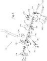
Figure 5 is as exploded view of a joystick control of an embodiment of the invention, -
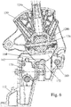
Figure 6 is a section through the joystick control ofFigure 5 through a plane passing through the shaft of the operating lever, and -
Figures 7a, 7b and 7c show sections through an interlock device for preventing an actuating member from moving when the other actuating member is not in its neutral position, the figures showing the interlock device in three different positions of the actuating members. -
Figures 1 to 4 show a joystick control of the type described initially. These figures are not of embodiments of the invention but will be described first to enable the later described embodiments of the invention to be understood more clearly. - The
joystick control 10, as most clearly shown inFigure 4 , comprises amain support body 12 formed withpillar blocks axle 18 is journalled onbearing bushes 20. Thesupport body 12 is formed in two symmetrical halves that are joined to one another by rolledsteel pins 22. Thepins 22 may be replaced by rivets, screws or bolts and serve only to hold the two halves of thesupport body 12 together. - An
operating lever 24 is connected to theaxle 18 by means of apivot pin 26. Theoperating lever 24 has ashaft 24a that is moved in the same way as the gear stick of a conventional H-gate gearbox, with afork 24b at one end that straddles theaxle 18 and receives thepin 26 which passes through ahole 18a in theaxle 18 extending at right angles to the rotational axis of theaxle 18. In this way, theshaft 24a can be pivoted about thepin 26 relative to theaxle 20 in the plane containing the axes of theaxle 18 and theshaft 24a but rotates with theaxle 18 in the orthogonal plane. - Two mirror symmetrical actuating
members 30 are mounted on theaxle 18 on opposite sides of theoperating lever 24. Each actuatingmember 30 has a sector-shaped part 32 centred on abearing 34 through which theaxle 18 passes. Each actuatingmember 30 also has anextension arm 36 having ahole 38 at its end to receive apin 40 by means of which thearm 36 is connected to the end of theinner cable 42 of a Bowdencable 44 of which the outer sheath is anchored to the support body 12 (seeFigure 1 ). Thus, rotation of each actuatingmember 30 clockwise as viewed inFigure 4 (i.e. counter-clockwise as view inFigure 1 ), will result in theinner cable 42 being extended, while rotation of an actuating member in the opposite direction will cause the connectedinner cable 42 to be retracted into its sheath. - The radially outer surfaces of the actuating
members 30 are formed withnotches 50 that can receive theshaft 24a of theoperating lever 24. Each notch is large enough to fully accommodate theshaft 24a so that when theshaft 24a rests within the notch of one actuating member, it lies totally outside the notch of the other actuating member. - At their opposite ends, the Bowden cable acts directly on two selectors of the gearbox. One of the Bowden cables moves a selector for engaging the first and second speeds and the other acts on a different selector used for engaging the third and fourth speeds.
- The joystick control is shown in
Figures 1 to 3 with theoperating lever 24 in the neutral position. Here, the twonotches 50 of the two actuating members are in line with one another and theoperating lever 24 can be pivoted about thepin 26 to rest wholly within eithernotch 50. Aspring 52 is used to bias the operating lever to the left as viewed inFigure 2 , to engage within the notch of the actuatingmember 30 for selecting the first and second speeds. - If the
operating lever 24 is moved from this rest position, clockwise as viewed inFigure 1 , this is equivalent to moving a gear stick up and will move the appropriate selector within the gearbox to select first speed. When the first speed is selected, theoperating lever 24 cannot be moved from side to side because it is no longer aligned with the notch of the other actuatingmember 30. Hence, there is no sloppy movement of operating lever and the only direction in which the operating lever can move is counter-clockwise back towards the neutral position. - In the same way, of the operating lever is moved down (counter-clockwise in
Figure 1 ) the second speed will the engaged. - Only while the gearbox is in neutral is it possible to disengage the
shaft 24a of theoperating lever 24 from thenotch 50 in one of the actuating member and engage it in thenotch 50 of the other. Thus after returning to neutral, theoperating lever 24 can be moved across to the engage in the notch of the actuatingmember 50 connected by the other Bowden cable to the second selector of the gearbox, to permit the third and fourth speeds to be selected by using theoperating lever 24 to rotate the other actuatingmember 30 is the appropriate direction. - Most of the components of the joystick control may be made of a plastics material. In particular, the
axle 18 may be formed of PPS (polyphenylene sulfide) polymer, thebearing bushes 20 of POM (polyoximethylene) omopolymer, and theoperating lever 24 and the actuatingmembers 30 of a glass fibre reinforced nylon such as PA66 35GF (polyamide with 35% glass fibre). - Referring now to
Figures 5 to 7 , to avoid unnecessary repetition, equivalent parts to those already described have been allocated similar reference numerals in the 100 series (i.e. each numeral has been augmented by 100) and will not be described again. - Two
cams 160 are secured to the lower edge as viewed of each of the actuatingmembers 130. As an alternative, thecams 160 can be formed as part of the actuatingmembers 130. Acam follower module 170 with tworoller followers 172 is mounted within thesupport body 112 and held in place by one of theroller steel pins 122. - The interaction between the
roller followers 172 and thecams 160 is best shown in the section ofFigure 6 . Each cam has acentral depression 162 that is aligned with the respective springbiased follower roller 172 when the actuatingmember 130 is in its neutral position. Theroller follower 172 acts as a ball catch, or a spring biased detent, to resist rotation of the actuating lever away from the neutral position. Theouter flanks 164 of thecams 160, on the other hand push the operating lever towards one or other of its end positions, once enough force has been applied to the operating lever to move it out of its neutral position against the action of theroller follower 172. - The
cams 160 in this way provide positive location of theoperating lever 124 in the neutral position and in its end positions, significantly improving the feel of thejoystick control 110 and rendering it more positive. - A further improvement of the joystick of the type described initially is achieved by providing an interlock that prevents an actuating
member 130 from moving when out of its neutral position when the other actuatingmember 130 has been moved out of its neutral position. - A suitable such interlock is shown in
Figure 7a to 7c . Apin 180 with tapered or rounded ends is mounted in a through bore in a part of thesupport body 112 lying between the two actuatingmembers 130. In the neutral position of both actuatingmembers 130, shown inFigure 7a , thepin 180 may be held by an optional spring (not shown) in a central position with its ends partially extending intoblind holes 130a in the actuatingmembers 130. Because of the shaping of the ends of thepin 180, as either of the actuatingmembers 130 is moved out of its neutral position, as shown inFigure 7b and 7c , it acts to displace thepin 180 into engagement in thehole 130a of the other actuatingmember 130, thereby locking the other actuatingmember 130 relative to thesupport body 112. - While the embodiment of the invention described in
Figure 5 has cams mounted on both of the actuatingmembers 130, it would be alternatively possible to mount a single cam on theoperating lever 124 to achieve the same effect.
Claims (11)
- A joystick control for a change speed gearbox, comprising a support body (112), an axle (118) rotatably supported by the body (112), an operating lever (124) connected to the axle (118) by a pivot pin (126) having an axis perpendicular to that of the axle (118) such that the operating lever (124) is rotatable about the axis of the axle (118) and is pivotable relative to the axle (18) about the axis of the pivot pin (126), two actuating members (130) rotatably supported by the axle (118) and arranged one on each side of the operating lever (124), each actuating member (130) being connectible to a respective Bowden cable (44) to extend and retract the cable (44) in response to rotation of the actuating member (124) about the axle (118), and mating (124a, 150) formations on the operating lever (124) and the actuating members (130) operative to engage the operating lever (124) selectively for rotation with one or the other of the actuating members (130) in dependence upon the direction in which the operating lever (130) is pivoted relative to the axle (18) about the pivot pin (126), characterised in that resiliently biased detents (160,170) are provided between the support body (112) and the actuating members (130) or the operating lever (124) to resist rotation of the operating lever (124) away from at least one defined stable position; and wherein an interlock device (180) is provided between the two actuating members (130) to prevent movement of each actuating member (130) relative to the support body (112) when the other actuating member is not in said at least one stable position.
- A joystick control as claimed in claim 1, wherein the actuating members (130) are formed or fitted with cams (160) each having at least one depression (162), the cams (160) being engaged by resiliently biased cam followers (172) mounted on the support body (112).
- A joystick control as claimed in claim 2, wherein the cam followers have rollers (172) that roll on the surfaces of the cams (160) as the actuating members (130) are rotated.
- A joystick control as claimed in claim 1, wherein the interlock device comprises a locking pin (180) slidably mounted in a through bore in a part of the support body (112) disposed between the two actuating members (130), the opposite ends of the pin (180) being receivable in holes (130a) in the actuating members (130), the holes (130a) and the pin (180) being such that in neutral positions of both actuating members (130) the pin (180) is biased towards a central position in which the ends of the pin (180) engage partially within the holes (130a) of both actuating members (130) but do not prevent rotation of either actuating member (130) and when either member (130) is rotated the pin (180) is ejected from the hole in that member and engaged further in the hole of the other member to prevent rotation of the other member relative to the support body (112)
- A joystick control as claimed in any preceding claim, wherein each of the actuating members (130) is rotatable by the operating lever between a neutral position, an "up" position in which the associated Bowden cable is extended and a "down" position in which the associated Bowden cable (44) is retracted.
- A joystick control as claimed in claim 5, wherein the mating formations (124a, 150) on the operating lever and the actuating members are such that the operating lever (124) may only be disengaged from one of the actuating members (130) and engaged with the other when both the actuating members (130) are in their respective neutral positions.
- A joystick control as claimed in any preceding claim, wherein the mating formations comprise notches (150) in the sides of the actuating members (130) for receiving the operating lever (124).
- A joystick control as claimed in Claim 7, wherein a spring (52) is provided to urge the operating lever (124) to engage in the notch (150) of one of the actuating members (30).
- A joystick control as claimed in any preceding claim, wherein the support body (112), the axle (118), the operating lever (124), and the actuating members (130) are formed of plastics materials.
- A joystick control as claimed in claim 9, wherein the plastics material of at least one of the operating lever (24), the actuating members (30) and the support body (12) is a glass fibre reinforced nylon.
- A gearbox connected by two Bowden cables to a joystick control as claimed in any preceding claim, wherein the gearbox has two gear ratio selectors, a first selector being movable by the first Bowden cable from a neutral position in one direction to select a first gear ratio and from the neutral position in the opposite direction to select a second gear ratio, and the second first selector being movable by the second Bowden cable from a neutral position in one direction to select a third gear ratio and from the neutral position in the opposite direction to select a fourth gear ratio, pivoting of the operating lever (24) about the pin (26) relative to the axle (18) having no effect on the Bowden cables nor on the positions of the gear ratio selectors.
Applications Claiming Priority (2)
| Application Number | Priority Date | Filing Date | Title |
|---|---|---|---|
| IT000072A ITMO20130072A1 (en) | 2013-03-20 | 2013-03-20 | CONTROL JOYSTICK FOR A SPEED CHANGE. |
| PCT/EP2014/055469 WO2014147105A1 (en) | 2013-03-20 | 2014-03-19 | A joystick control for a change speed gearbox |
Publications (2)
| Publication Number | Publication Date |
|---|---|
| EP2976553A1 EP2976553A1 (en) | 2016-01-27 |
| EP2976553B1 true EP2976553B1 (en) | 2016-12-28 |
Family
ID=48227437
Family Applications (1)
| Application Number | Title | Priority Date | Filing Date |
|---|---|---|---|
| EP14710903.7A Active EP2976553B1 (en) | 2013-03-20 | 2014-03-19 | A joystick control for a change speed gearbox |
Country Status (6)
| Country | Link |
|---|---|
| US (1) | US10054219B2 (en) |
| EP (1) | EP2976553B1 (en) |
| CN (1) | CN105247250B (en) |
| BR (1) | BR112015024227B1 (en) |
| IT (1) | ITMO20130072A1 (en) |
| WO (1) | WO2014147105A1 (en) |
Families Citing this family (6)
| Publication number | Priority date | Publication date | Assignee | Title |
|---|---|---|---|---|
| US10563752B2 (en) * | 2014-12-19 | 2020-02-18 | Kongsberg Automotive Ab | Gear shifter assembly for a vehicle |
| EP3511597B1 (en) * | 2018-01-15 | 2020-02-26 | FCA Italy S.p.A. | Control device for a vehicle gearshift |
| KR101995308B1 (en) * | 2018-01-16 | 2019-07-03 | 경창산업주식회사 | Electronic Shift Control Device |
| CN108547941A (en) * | 2018-06-21 | 2018-09-18 | 洛阳市黄河软轴控制器股份有限公司 | Trailer reversing control mechanism and its application method |
| DE102019202283A1 (en) * | 2019-02-20 | 2020-08-20 | Zf Friedrichshafen Ag | Shifting device for a user input for shifting a vehicle transmission and transmission system for a vehicle |
| US12330793B2 (en) | 2022-09-19 | 2025-06-17 | Ami Industries, Inc. | Method for translating pins using a rotary actuator |
Family Cites Families (20)
| Publication number | Priority date | Publication date | Assignee | Title |
|---|---|---|---|---|
| US4328712A (en) * | 1980-01-24 | 1982-05-11 | Jsj Corporation | Lockout for gimbal-type automotive transmission gear shifter |
| SE512418C2 (en) * | 1998-06-29 | 2000-03-13 | Kongsberg Automotive Ab | Operating device |
| US6325196B1 (en) * | 1999-07-29 | 2001-12-04 | Grand Haven Stamped Products, Division Of Jsj Corporation | Shifter with park lock and neutral lock device |
| US6568294B2 (en) * | 2000-02-22 | 2003-05-27 | Grand Haven Stamped Products, Division Of Jsj Corporation | Shifter with automatic and manual shift modes and with shift position indicators |
| DE10022433B4 (en) * | 2000-05-09 | 2006-07-13 | Daimlerchrysler Ag | lever device |
| JP4668439B2 (en) * | 2001-03-12 | 2011-04-13 | 株式会社東海理化電機製作所 | Shift lever device |
| JP2004009807A (en) * | 2002-06-04 | 2004-01-15 | Kubota Corp | Transmission operating device |
| KR100488693B1 (en) * | 2002-06-27 | 2005-05-11 | 현대자동차주식회사 | Lever apparatus of automatic transmission having an manual mode switch |
| JP4047643B2 (en) * | 2002-07-03 | 2008-02-13 | デルタ工業株式会社 | Shift device for automatic transmission for vehicle |
| US20040168537A1 (en) * | 2003-02-28 | 2004-09-02 | Teleflex Incorporated | Shifter assembly for an automatic transmission |
| JP2005119394A (en) * | 2003-10-15 | 2005-05-12 | Atsumi Tec:Kk | Automatic transmission operation device for vehicle |
| DE602004022016D1 (en) * | 2004-03-01 | 2009-08-27 | Ford Global Tech Llc | Shift mechanism for manual transmission |
| US7469614B2 (en) * | 2004-03-30 | 2008-12-30 | Dura Global Technologies, Inc. | Electronic actuated shifter for automatic transmissions |
| US7597023B2 (en) * | 2005-10-17 | 2009-10-06 | Dura Global Technologies, Inc. | Shifter mechanism with secondary detent |
| JP2008105584A (en) * | 2006-10-26 | 2008-05-08 | Tokai Rika Co Ltd | Shift lever device |
| DE202008000715U1 (en) * | 2008-01-17 | 2008-04-03 | Dura Automotive Systems Einbeck Gmbh | Hand shift lever assembly |
| DE102008022561B4 (en) * | 2008-04-30 | 2021-04-29 | Dr. Ing. H.C. F. Porsche Aktiengesellschaft | Switching device for an automatic transmission |
| KR101459799B1 (en) * | 2009-12-04 | 2014-11-07 | 현대자동차주식회사 | The electronic shift control device of a vehicle |
| IT1401003B1 (en) * | 2010-06-15 | 2013-07-05 | Cnh Italia Spa | JOYSTICK CHECK FOR A SPEED CHANGE |
| CN202125589U (en) * | 2011-06-29 | 2012-01-25 | 上海申赛机电控制技术有限公司 | Integrated shift selector |
-
2013
- 2013-03-20 IT IT000072A patent/ITMO20130072A1/en unknown
-
2014
- 2014-03-19 WO PCT/EP2014/055469 patent/WO2014147105A1/en not_active Ceased
- 2014-03-19 EP EP14710903.7A patent/EP2976553B1/en active Active
- 2014-03-19 BR BR112015024227-8A patent/BR112015024227B1/en active IP Right Grant
- 2014-03-19 US US14/776,818 patent/US10054219B2/en active Active
- 2014-03-19 CN CN201480024005.6A patent/CN105247250B/en not_active Expired - Fee Related
Non-Patent Citations (1)
| Title |
|---|
| None * |
Also Published As
| Publication number | Publication date |
|---|---|
| BR112015024227A2 (en) | 2017-07-18 |
| US10054219B2 (en) | 2018-08-21 |
| EP2976553A1 (en) | 2016-01-27 |
| WO2014147105A1 (en) | 2014-09-25 |
| CN105247250B (en) | 2017-06-13 |
| BR112015024227B1 (en) | 2021-12-07 |
| ITMO20130072A1 (en) | 2014-09-21 |
| CN105247250A (en) | 2016-01-13 |
| US20160040778A1 (en) | 2016-02-11 |
Similar Documents
| Publication | Publication Date | Title |
|---|---|---|
| US10054219B2 (en) | Joystick control for a change speed gearbox | |
| DE69701922T2 (en) | Control device for a bicycle gear shift | |
| JP5909400B2 (en) | Parking lock mechanism | |
| DE10231015B4 (en) | Motion translator for an isodistant switching sensor | |
| RU2719090C1 (en) | Actuator of drive from gear shifting quadrant | |
| US4583418A (en) | Selecting mechanism for vehicular transmission operating apparatus | |
| CN101802461A (en) | Adjustment mechanism for a speed-change cable of a manual transmission | |
| DE202013001399U1 (en) | Bicycle actuator | |
| US9291258B2 (en) | Joystick control for a change speed gearbox | |
| BR102013013150A2 (en) | DEVICE FOR SELECTING AND COUPLING GEARS FROM A TRANSMISSION BOX FOR CAR VEHICLES | |
| US7654170B2 (en) | Centering spring apparatus for a transmission shift control mechanism | |
| US9347556B2 (en) | Dual shift fork | |
| KR101637693B1 (en) | Shifting apparatus for manual transmission | |
| WO2020135917A1 (en) | Shifting device for shifting a gearbox | |
| EP2273158B1 (en) | Control system for a gearbox | |
| CN101395411B (en) | gear shifter | |
| WO2016177429A1 (en) | Pull-pull shifter assembly | |
| US9268353B2 (en) | Operating mechanism for a Bowden cable | |
| WO2013132281A1 (en) | Selector apparatus for a vehicle | |
| CN203832258U (en) | Structure for locking speed-variable operating rod at position and speed-variable operating system with same | |
| US20190195362A1 (en) | Interlock mechanism | |
| KR100916201B1 (en) | Interlock Body Control for Manual Transmission | |
| KR100891514B1 (en) | Shift device of manual transmission | |
| CZ299200B6 (en) | Gear selector for change gear box, particularly for motor vehicles | |
| JP6090349B2 (en) | Transmission operating mechanism of transmission |
Legal Events
| Date | Code | Title | Description |
|---|---|---|---|
| PUAI | Public reference made under article 153(3) epc to a published international application that has entered the european phase |
Free format text: ORIGINAL CODE: 0009012 |
|
| 17P | Request for examination filed |
Effective date: 20151020 |
|
| AK | Designated contracting states |
Kind code of ref document: A1 Designated state(s): AL AT BE BG CH CY CZ DE DK EE ES FI FR GB GR HR HU IE IS IT LI LT LU LV MC MK MT NL NO PL PT RO RS SE SI SK SM TR |
|
| AX | Request for extension of the european patent |
Extension state: BA ME |
|
| DAX | Request for extension of the european patent (deleted) | ||
| GRAP | Despatch of communication of intention to grant a patent |
Free format text: ORIGINAL CODE: EPIDOSNIGR1 |
|
| RIC1 | Information provided on ipc code assigned before grant |
Ipc: F16H 59/04 20060101AFI20160627BHEP Ipc: F16H 63/38 20060101ALI20160627BHEP Ipc: F16H 61/36 20060101ALI20160627BHEP |
|
| INTG | Intention to grant announced |
Effective date: 20160728 |
|
| STAA | Information on the status of an ep patent application or granted ep patent |
Free format text: STATUS: GRANT OF PATENT IS INTENDED |
|
| GRAS | Grant fee paid |
Free format text: ORIGINAL CODE: EPIDOSNIGR3 |
|
| GRAA | (expected) grant |
Free format text: ORIGINAL CODE: 0009210 |
|
| STAA | Information on the status of an ep patent application or granted ep patent |
Free format text: STATUS: THE PATENT HAS BEEN GRANTED |
|
| AK | Designated contracting states |
Kind code of ref document: B1 Designated state(s): AL AT BE BG CH CY CZ DE DK EE ES FI FR GB GR HR HU IE IS IT LI LT LU LV MC MK MT NL NO PL PT RO RS SE SI SK SM TR |
|
| REG | Reference to a national code |
Ref country code: GB Ref legal event code: FG4D |
|
| REG | Reference to a national code |
Ref country code: CH Ref legal event code: EP |
|
| REG | Reference to a national code |
Ref country code: GB Ref legal event code: 746 Effective date: 20161221 Ref country code: FR Ref legal event code: PLFP Year of fee payment: 4 |
|
| REG | Reference to a national code |
Ref country code: DE Ref legal event code: R084 Ref document number: 602014005855 Country of ref document: DE |
|
| REG | Reference to a national code |
Ref country code: AT Ref legal event code: REF Ref document number: 857597 Country of ref document: AT Kind code of ref document: T Effective date: 20170115 |
|
| REG | Reference to a national code |
Ref country code: IE Ref legal event code: FG4D |
|
| REG | Reference to a national code |
Ref country code: DE Ref legal event code: R096 Ref document number: 602014005855 Country of ref document: DE |
|
| PG25 | Lapsed in a contracting state [announced via postgrant information from national office to epo] |
Ref country code: LV Free format text: LAPSE BECAUSE OF FAILURE TO SUBMIT A TRANSLATION OF THE DESCRIPTION OR TO PAY THE FEE WITHIN THE PRESCRIBED TIME-LIMIT Effective date: 20161228 |
|
| REG | Reference to a national code |
Ref country code: LT Ref legal event code: MG4D |
|
| PG25 | Lapsed in a contracting state [announced via postgrant information from national office to epo] |
Ref country code: LT Free format text: LAPSE BECAUSE OF FAILURE TO SUBMIT A TRANSLATION OF THE DESCRIPTION OR TO PAY THE FEE WITHIN THE PRESCRIBED TIME-LIMIT Effective date: 20161228 Ref country code: GR Free format text: LAPSE BECAUSE OF FAILURE TO SUBMIT A TRANSLATION OF THE DESCRIPTION OR TO PAY THE FEE WITHIN THE PRESCRIBED TIME-LIMIT Effective date: 20170329 Ref country code: NO Free format text: LAPSE BECAUSE OF FAILURE TO SUBMIT A TRANSLATION OF THE DESCRIPTION OR TO PAY THE FEE WITHIN THE PRESCRIBED TIME-LIMIT Effective date: 20170328 Ref country code: SE Free format text: LAPSE BECAUSE OF FAILURE TO SUBMIT A TRANSLATION OF THE DESCRIPTION OR TO PAY THE FEE WITHIN THE PRESCRIBED TIME-LIMIT Effective date: 20161228 |
|
| REG | Reference to a national code |
Ref country code: NL Ref legal event code: MP Effective date: 20161228 |
|
| REG | Reference to a national code |
Ref country code: AT Ref legal event code: MK05 Ref document number: 857597 Country of ref document: AT Kind code of ref document: T Effective date: 20161228 |
|
| PG25 | Lapsed in a contracting state [announced via postgrant information from national office to epo] |
Ref country code: RS Free format text: LAPSE BECAUSE OF FAILURE TO SUBMIT A TRANSLATION OF THE DESCRIPTION OR TO PAY THE FEE WITHIN THE PRESCRIBED TIME-LIMIT Effective date: 20161228 Ref country code: HR Free format text: LAPSE BECAUSE OF FAILURE TO SUBMIT A TRANSLATION OF THE DESCRIPTION OR TO PAY THE FEE WITHIN THE PRESCRIBED TIME-LIMIT Effective date: 20161228 Ref country code: FI Free format text: LAPSE BECAUSE OF FAILURE TO SUBMIT A TRANSLATION OF THE DESCRIPTION OR TO PAY THE FEE WITHIN THE PRESCRIBED TIME-LIMIT Effective date: 20161228 |
|
| PG25 | Lapsed in a contracting state [announced via postgrant information from national office to epo] |
Ref country code: NL Free format text: LAPSE BECAUSE OF FAILURE TO SUBMIT A TRANSLATION OF THE DESCRIPTION OR TO PAY THE FEE WITHIN THE PRESCRIBED TIME-LIMIT Effective date: 20161228 |
|
| PG25 | Lapsed in a contracting state [announced via postgrant information from national office to epo] |
Ref country code: CZ Free format text: LAPSE BECAUSE OF FAILURE TO SUBMIT A TRANSLATION OF THE DESCRIPTION OR TO PAY THE FEE WITHIN THE PRESCRIBED TIME-LIMIT Effective date: 20161228 Ref country code: SK Free format text: LAPSE BECAUSE OF FAILURE TO SUBMIT A TRANSLATION OF THE DESCRIPTION OR TO PAY THE FEE WITHIN THE PRESCRIBED TIME-LIMIT Effective date: 20161228 Ref country code: IS Free format text: LAPSE BECAUSE OF FAILURE TO SUBMIT A TRANSLATION OF THE DESCRIPTION OR TO PAY THE FEE WITHIN THE PRESCRIBED TIME-LIMIT Effective date: 20170428 Ref country code: EE Free format text: LAPSE BECAUSE OF FAILURE TO SUBMIT A TRANSLATION OF THE DESCRIPTION OR TO PAY THE FEE WITHIN THE PRESCRIBED TIME-LIMIT Effective date: 20161228 Ref country code: RO Free format text: LAPSE BECAUSE OF FAILURE TO SUBMIT A TRANSLATION OF THE DESCRIPTION OR TO PAY THE FEE WITHIN THE PRESCRIBED TIME-LIMIT Effective date: 20161228 |
|
| PG25 | Lapsed in a contracting state [announced via postgrant information from national office to epo] |
Ref country code: BE Free format text: LAPSE BECAUSE OF FAILURE TO SUBMIT A TRANSLATION OF THE DESCRIPTION OR TO PAY THE FEE WITHIN THE PRESCRIBED TIME-LIMIT Effective date: 20161228 Ref country code: BG Free format text: LAPSE BECAUSE OF FAILURE TO SUBMIT A TRANSLATION OF THE DESCRIPTION OR TO PAY THE FEE WITHIN THE PRESCRIBED TIME-LIMIT Effective date: 20170328 Ref country code: AT Free format text: LAPSE BECAUSE OF FAILURE TO SUBMIT A TRANSLATION OF THE DESCRIPTION OR TO PAY THE FEE WITHIN THE PRESCRIBED TIME-LIMIT Effective date: 20161228 Ref country code: PL Free format text: LAPSE BECAUSE OF FAILURE TO SUBMIT A TRANSLATION OF THE DESCRIPTION OR TO PAY THE FEE WITHIN THE PRESCRIBED TIME-LIMIT Effective date: 20161228 Ref country code: PT Free format text: LAPSE BECAUSE OF FAILURE TO SUBMIT A TRANSLATION OF THE DESCRIPTION OR TO PAY THE FEE WITHIN THE PRESCRIBED TIME-LIMIT Effective date: 20170428 Ref country code: SM Free format text: LAPSE BECAUSE OF FAILURE TO SUBMIT A TRANSLATION OF THE DESCRIPTION OR TO PAY THE FEE WITHIN THE PRESCRIBED TIME-LIMIT Effective date: 20161228 Ref country code: ES Free format text: LAPSE BECAUSE OF FAILURE TO SUBMIT A TRANSLATION OF THE DESCRIPTION OR TO PAY THE FEE WITHIN THE PRESCRIBED TIME-LIMIT Effective date: 20161228 |
|
| REG | Reference to a national code |
Ref country code: DE Ref legal event code: R097 Ref document number: 602014005855 Country of ref document: DE |
|
| REG | Reference to a national code |
Ref country code: CH Ref legal event code: PL |
|
| PLBE | No opposition filed within time limit |
Free format text: ORIGINAL CODE: 0009261 |
|
| STAA | Information on the status of an ep patent application or granted ep patent |
Free format text: STATUS: NO OPPOSITION FILED WITHIN TIME LIMIT |
|
| PG25 | Lapsed in a contracting state [announced via postgrant information from national office to epo] |
Ref country code: MC Free format text: LAPSE BECAUSE OF FAILURE TO SUBMIT A TRANSLATION OF THE DESCRIPTION OR TO PAY THE FEE WITHIN THE PRESCRIBED TIME-LIMIT Effective date: 20161228 Ref country code: DK Free format text: LAPSE BECAUSE OF FAILURE TO SUBMIT A TRANSLATION OF THE DESCRIPTION OR TO PAY THE FEE WITHIN THE PRESCRIBED TIME-LIMIT Effective date: 20161228 |
|
| 26N | No opposition filed |
Effective date: 20170929 |
|
| REG | Reference to a national code |
Ref country code: IE Ref legal event code: MM4A |
|
| REG | Reference to a national code |
Ref country code: FR Ref legal event code: PLFP Year of fee payment: 5 |
|
| PG25 | Lapsed in a contracting state [announced via postgrant information from national office to epo] |
Ref country code: LU Free format text: LAPSE BECAUSE OF NON-PAYMENT OF DUE FEES Effective date: 20170319 |
|
| PG25 | Lapsed in a contracting state [announced via postgrant information from national office to epo] |
Ref country code: LI Free format text: LAPSE BECAUSE OF NON-PAYMENT OF DUE FEES Effective date: 20170331 Ref country code: CH Free format text: LAPSE BECAUSE OF NON-PAYMENT OF DUE FEES Effective date: 20170331 Ref country code: SI Free format text: LAPSE BECAUSE OF FAILURE TO SUBMIT A TRANSLATION OF THE DESCRIPTION OR TO PAY THE FEE WITHIN THE PRESCRIBED TIME-LIMIT Effective date: 20161228 Ref country code: IE Free format text: LAPSE BECAUSE OF NON-PAYMENT OF DUE FEES Effective date: 20170319 |
|
| PG25 | Lapsed in a contracting state [announced via postgrant information from national office to epo] |
Ref country code: MT Free format text: LAPSE BECAUSE OF NON-PAYMENT OF DUE FEES Effective date: 20170319 |
|
| PG25 | Lapsed in a contracting state [announced via postgrant information from national office to epo] |
Ref country code: HU Free format text: LAPSE BECAUSE OF FAILURE TO SUBMIT A TRANSLATION OF THE DESCRIPTION OR TO PAY THE FEE WITHIN THE PRESCRIBED TIME-LIMIT; INVALID AB INITIO Effective date: 20140319 |
|
| PG25 | Lapsed in a contracting state [announced via postgrant information from national office to epo] |
Ref country code: CY Free format text: LAPSE BECAUSE OF FAILURE TO SUBMIT A TRANSLATION OF THE DESCRIPTION OR TO PAY THE FEE WITHIN THE PRESCRIBED TIME-LIMIT Effective date: 20161228 |
|
| PG25 | Lapsed in a contracting state [announced via postgrant information from national office to epo] |
Ref country code: MK Free format text: LAPSE BECAUSE OF FAILURE TO SUBMIT A TRANSLATION OF THE DESCRIPTION OR TO PAY THE FEE WITHIN THE PRESCRIBED TIME-LIMIT Effective date: 20161228 |
|
| PG25 | Lapsed in a contracting state [announced via postgrant information from national office to epo] |
Ref country code: TR Free format text: LAPSE BECAUSE OF FAILURE TO SUBMIT A TRANSLATION OF THE DESCRIPTION OR TO PAY THE FEE WITHIN THE PRESCRIBED TIME-LIMIT Effective date: 20161228 |
|
| REG | Reference to a national code |
Ref country code: DE Ref legal event code: R082 Ref document number: 602014005855 Country of ref document: DE Representative=s name: MEISSNER BOLTE PATENTANWAELTE RECHTSANWAELTE P, DE |
|
| PG25 | Lapsed in a contracting state [announced via postgrant information from national office to epo] |
Ref country code: AL Free format text: LAPSE BECAUSE OF FAILURE TO SUBMIT A TRANSLATION OF THE DESCRIPTION OR TO PAY THE FEE WITHIN THE PRESCRIBED TIME-LIMIT Effective date: 20161228 |
|
| PGFP | Annual fee paid to national office [announced via postgrant information from national office to epo] |
Ref country code: GB Payment date: 20260319 Year of fee payment: 13 |
|
| PGFP | Annual fee paid to national office [announced via postgrant information from national office to epo] |
Ref country code: DE Payment date: 20260320 Year of fee payment: 13 |
|
| PGFP | Annual fee paid to national office [announced via postgrant information from national office to epo] |
Ref country code: IT Payment date: 20260320 Year of fee payment: 13 |
|
| PGFP | Annual fee paid to national office [announced via postgrant information from national office to epo] |
Ref country code: FR Payment date: 20260323 Year of fee payment: 13 |