EP2976544B1 - Adaptive elastic bearing and tuned mass damper containing same - Google Patents
Adaptive elastic bearing and tuned mass damper containing same Download PDFInfo
- Publication number
- EP2976544B1 EP2976544B1 EP14714584.1A EP14714584A EP2976544B1 EP 2976544 B1 EP2976544 B1 EP 2976544B1 EP 14714584 A EP14714584 A EP 14714584A EP 2976544 B1 EP2976544 B1 EP 2976544B1
- Authority
- EP
- European Patent Office
- Prior art keywords
- cone
- elements
- elastomer layer
- vibration absorber
- elastomer
- Prior art date
- Legal status (The legal status is an assumption and is not a legal conclusion. Google has not performed a legal analysis and makes no representation as to the accuracy of the status listed.)
- Active
Links
Images


Classifications
-
- F—MECHANICAL ENGINEERING; LIGHTING; HEATING; WEAPONS; BLASTING
- F16—ENGINEERING ELEMENTS AND UNITS; GENERAL MEASURES FOR PRODUCING AND MAINTAINING EFFECTIVE FUNCTIONING OF MACHINES OR INSTALLATIONS; THERMAL INSULATION IN GENERAL
- F16F—SPRINGS; SHOCK-ABSORBERS; MEANS FOR DAMPING VIBRATION
- F16F1/00—Springs
- F16F1/36—Springs made of rubber or other material having high internal friction, e.g. thermoplastic elastomers
- F16F1/38—Springs made of rubber or other material having high internal friction, e.g. thermoplastic elastomers with a sleeve of elastic material between a rigid outer sleeve and a rigid inner sleeve or pin, i.e. bushing-type
- F16F1/393—Springs made of rubber or other material having high internal friction, e.g. thermoplastic elastomers with a sleeve of elastic material between a rigid outer sleeve and a rigid inner sleeve or pin, i.e. bushing-type with spherical or conical sleeves
- F16F1/3935—Conical sleeves
Definitions
- the invention relates to equipped with elastic means bearing and vibration absorber containing them with variable so adaptive stiffness, which can be targeted thereby adjusted to the occurring in the system to be damped or machine different exciter frequencies and adjusted.
- the variable rigidity is achieved by setting appropriately placed compressible free spaces within the bearing, which can be selectively filled with elastomeric material.
- the invention particularly relates to such adaptive vibration absorbers according to the invention, which are able to dampen vibrations generated by different frequencies, in which the rigidity of the elastic means can be changed controllably and variably.
- the vibration absorbers according to the invention are particularly suitable for use in wind turbines.
- vibration dampers known in the art are used for a particular frequency. In variable speed machines and thus different excitation frequency, it is necessary to adapt the vibration damper to the respective frequency.
- WO 2013/023 724 A1 describes an adjustable vibration damper with the features of the preamble of claim 1.
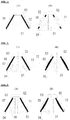
- a component consists of an inner cone (01), the rotationally symmetrical elastomer layer (05) and an outer cone position (02).
- the elastomer layer is continuous between the cones. This has a barely changeable relatively high rigidity.
- Such absorbers are in the Stan of the art described.
- Fig. 1B is said elastomer layer (opposite Fig. 1A ) interrupted in the middle, so that a free space (06) is formed.
- This component has a much lower rigidity than the component in Fig. 1A ,
- the stiffness ratio depends on how long the rubber layers (03) and (04) are in relation to the clearance (06). (Length [12-11] to length [12]).
- Fig. 1 - 3 show in simplified form the basic mode of operation of the vibration absorber according to the invention: between maximum rigidity ( Fig. 1A ) and lowest rigidity ( Fig. 1B ) can be adjusted by setting appropriate clearances almost any desired stiffness between the two extremes, and thus influence on the vibration frequencies to be damped.
- the free spaces can be produced in various ways: either the elastomer layer between the cones has a recess, for example a bulbous recess, or else the corresponding solid conical part has such an all-round bulbous, concave, convex or otherwise shaped recess or hollow structure.
- the inner cone must be moved against the respective outer cone. This can be done by means of a linear drive (motor with spindle), electromagnetic, pneumatic, hydraulic or mixed forms of this, if necessary, involving an electronic control done. It can be usefully used the corresponding conical spring element (cone element) itself as a hydraulic or pneumatic element.
- a cone bearing is understood to mean a bearing which has an inner cone element and an outer cone element which are connected to one another by at least one elastic layer. Both cone elements have an axial central bore.
- Such a cone bearing is also referred to as a single cone bearing.
- a Mehrfachkonus can be used, which is composed of a said outer cone member and a said inner cone member and one or more insects, which in turn are all interconnected by elastic layers.
- an array of conical bearings is also understood to mean a grouping of at least two cone bearings (single or multiple cone bearings) which are located opposite and functionally related, with the conical elements either facing with their broad base, or with their narrow base, or else arranged so that the broad base of one cone element faces the narrow base of the opposite cone part.
- Such an arrangement of two cone bearings is also referred to as double cone bearings according to this invention.
- the vibration absorbers according to the invention always have at least one corresponding double cone bearing, but may also have a plurality of double cone bearings.
- the subject matter of the invention is therefore an adaptive and optionally active vibration absorber having the features of claim 1.
- This claim relates to a vibration damper with adjustable stiffness adapted to the excitation frequency, comprising at least one rotationally symmetric inelastic, preferably conical inner cone element (01) ( 108 (307) (804) and at least one rotationally symmetric, inelastic, preferably conical outer cone element (02) (202) (805) which is inserted over the inner cone element, inner cone element and outer cone element being formed by a single- or multilayer elastomer layer (101 ) (208) (303) (304) (310) are connected to one another and in each case have a cylindrical bore centrally in the axial direction for receiving fastening or tensioning devices, wherein in the region of the elastomer layer (101) (208) (303) (304 ) (310) along the interface to the inner cone and / or outer cone element in a non-strained state existing shaped according to the cone elements preferably rotationally symmetrical free space (06) (103) (308) (
- said clearance (06) (103) (308) (802) formed at the interface of the elastomeric layer (101) (208) (303) (304) (310) has a bulbous, concave or convex or otherwise geometric Shape, which is achieved by appropriate design of the elastomer layer but also the conical inner and / or outer cone in this area.
- the cone-shaped clearance (06) (103) (308) (802) along the interface between elastomeric layer (101) (208) (303) (304) (310) and inner cone or between Elastomer layer and outer cone have a length corresponding to 20 to 80%, preferably 40-70% of the length of the cone or the length of the elastomer layer between the cones.
- the cone-shaped clearance (06) (103) (308) (802) along the elastomeric layer / inner cone interface or between the elastomeric layer and outer cone should have a thickness that is 5-30%, preferably 10-20% of the thickness of the elastomeric layer between the Coning matches.
- the stiffness can be adapted and variably adjusted by the bearings, above all in the axial direction (z-axis) but also in the radial direction (x, y), wherein the radial stiffness in is not as strongly influenced at a fixed cone angle as in the axial direction and distributed without further action more or less evenly in the x and y direction.
- the cone-shaped elastomeric layer (101) (208) (303) (304) (310) may have direct access (2002) at one or more locations have mechanical or hydraulic means, wherein the access is placed so that in the radial (x, y) direction an adaptable variable stiffness is achieved, which varies in the x and y direction.
- the conical bearings may additionally comprise further elastomer layers and further conical elements. Furthermore, the cone angle ⁇ of a cone element can be smaller than the cone angle of another cone element, so that radial and axial vibrations can be influenced differently by the different cone angles.
- two conical bearings positioned opposite one another can be arranged so close to one another that a gap (802) is present in the unstressed state. This gap can be partially or completely closed by clamping the cone elements of the bearing, so that in this way the rigidity can additionally be influenced ( Fig. 24 ).
- the conical bearing or assembly of cone bearings has two cone bearings forming a double cone bearing, which are arranged opposite to their broad and / or short cone base.
- a mechanical, pneumatic, hydraulic or magnetic device that allows the respective freely movable inner cone elements or outer cone elements of the two cone bearings axially preferably against the respective fixed brieflykonuslemente or inner cone elements can be moved, and thus elastomeric material can be pressed into the said free spaces of the bearing.
- the axial displacement of the cone elements can be carried out actively or passively by hydraulic, pneumatic, mechanical or magnetic means.
- the axial displacement of the functional cone elements by one or more flat magnets is preferably carried out by active control, as described in more detail below.
- the subject matter is further a double cone bearing, in which two single or multiple cone bearings, as defined above or in the claims, are arranged with their wide or narrow base opposite, the inner cone elements (01) (108 (307) (804) via an elastomer layer (1 ) are connected to an axial cylindrical sleeve (13) about the central axial bore, and pressure means are provided by means of which the respective cone elements of the cone bearings can be moved in the axial direction, whereby said free spaces (06) (103) (308) in
- a pressure chamber is preferably located between the two opposing conical bearings, which can be pressurized by means of mechanical, hydraulic, pneumatic or magnetic means, so that the pressure can be applied to the cones respective freely movable inner cone elements axially apart and geg and their elastomeric material (101) (208) (303) (304) (310) is pressed into said free space (06) (103) (308) of the bearings.
- the invention also includes such bearings in which freely movable outer cone elements can be displaced against firmly mounted inner
- the invention relates to vibration absorbers comprising a damping mass and at least one double cone bearing, as described above and following. and defined in the features of claim 1.
- a vibration absorber according to the invention can be constructed from one, two, three or more, preferably functionally cooperating double cone bearings.
- the corresponding cone bearings or arrangements of conical bearings, in particular double cone bearings, and the corresponding equipped with these bearings vibration absorber can be used in particular for damping vibrations in systems and machines with variable speed and / or excitation frequency, especially in wind turbines.
- the invention thus also relates to wind turbines in which the vibration absorbers according to the invention are arranged in the region of the rotor hub, the rotor blades, the gear train or the tower, preferably 4-48, preferably 6-36, vibration absorbers preferably being arranged symmetrically in the area of the rotor hub. to reduce vibration due to speed changes of the rotor and / or gearbox.
- the principle of the invention can also be applied in principle to absorbers and bearings in these absorbers, which relate not only to the corresponding described double or multiple cone elements, but also to corresponding absorbers and bearings based on appropriately equipped cylindrical elastic double or multiple bushings with corresponding clearances, Columns, cavities, which can be closed completely or completely by displacing inner and outer cylindrical bushes and thus causing injection of elastomeric material, whereby the rigidity can be adjusted adaptively and regulatedly ( Fig. 10 - 12 )
- an adaptive bushing bearing or an arrangement of single or multiple bushings with stiffness adapted to the excitation frequency essentially comprising at least one rotationally symmetric inelastic, preferably cylindrical, inner bushing element and at least one rotationally symmetric inelastic, preferably cylindrical, outer bushing element which fits is inserted over the inner socket member, said inner sleeve member and outer sleeve member are connected by a single or multi-layer elastomer layer with each other and each have centrally in the axial direction a cylindrical bore for receiving fastening or bracing devices, wherein in the elastomer layer along the interface to mecanicbuchsen- and / or outer sleeve member is provided in a non-strained state according to the socket elements shaped rotationally symmetric free space, the teilwei se or completely can take the interface between predominantlybuchsen-, and inner sleeve member, and the inner sleeve member and / or outer sleeve member in the axial
- the absorbers of the invention as described in more detail below, own, as already said, especially for their use in wind turbines. Further fields of application are the vehicle sector, in particular bogies and wagons of railway vehicles, agricultural machines, construction vehicles, cranes, ships in the drive area and in the entire ship's skin and on cultivation parts and internal equipment, in particular in passenger ships.
- adaptive absorbers and bearings are described in which the natural frequency of the spring system can be adjusted by different possibilities. Due to the special construction with correspondingly positioned free spaces and gaps, according to the invention increases in rigidity can be achieved by a factor of 10 to 150, which corresponds to an addressable frequency range to be damped by a factor of 3 to 12 compared with a conventional elastic bearing or absorber of the prior art of the technique.
- the bearing / absorber system is usually used as the core of vibration absorbers, which are to work in a wide frequency range.
- adjustable vibrating damper according to the invention, that is, by applying a force in excitation frequency.
- the advantage of this is that a larger vibration damper effect with the same mass or the same effect can be achieved with significantly less mass.
- the invention thus also relates to a corresponding adaptive and active vibration absorber, which can also be actively operated.
- Active vibration absorbers are usually powered by immersion coil systems.
- immersion coil systems In our system, which is designed for small amplitudes, electro-train-pressure magnets are used. In contrast to immersion coils, these allow only small spring travel, but can cause significantly higher forces.
- Activation of the absorber according to the invention can be achieved, for example, by additionally arranged electromagnets.
- electromagnets for this purpose, it has surprisingly been found that flat magnets, in particular flat electro-train pressure magnets, for this purpose are ideally suited in contrast to the previously known in the prior art plunger coils.
- the advantage of flat magnets is that they can develop large forces on a small abdominal cavity and are also less expensive and less sensitive than immersion coils.
- FIG. 4 One possible embodiment shows an example Fig. 4 ,
- two conical rotationally symmetrical elastomer bearings are braced against each other so that creates a cavity between the two elements.
- a cylindrical elastomeric spring (1) Parallel to the conical elastomer spring, a cylindrical elastomeric spring (1) is arranged.
- This has a high radial stiffness, which is significantly higher than that of the conical elastomer elements (2).
- the elastomer spring is displaceable.
- the two intermediate cone (8) are moved in the axial direction. The movement is activated by applying pressure to the pressure chamber (4) via a pressure connection (5), so that the two intermediate cones (8) move away from one another and cause compression in the elastomer layers (2).
- the elastomer layers (2) are compressed in a controlled manner, then the free space (3) to be filled up for stiffening closes continuously until it is completely closed.
- the rigidity of the two conical bearings in the radial direction and also in the axial direction can be significantly increased.
- factor 10 to about factor 100 in rigidity can be achieved here.
- the frequency shift is thus possible without further measures by a factor of 3 - 10.
- compressed air or a liquid is used as the pressure element. Due to the fact that no sliding elements are present, water, or even water-glycol can be used as liquid. In principle, all liquids can be used when the elastomer is adapted to the liquid.
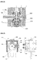
- Fig. 5 shows a further embodiment in which the area to be filled for stiffening (103) by an additional sliding element (102) is closed.
- the sliding elements (102) are pressed against the gap (103), for example by means of hydraulic or pneumatic pressure.
- the required pressure is applied in the pressure chambers (104).
- a membrane (112) is arranged, so that no liquid can penetrate into the gap (103).
- the rotationally symmetric component includes a conical elastomeric layer which communicates with a cylindrical elastomeric layer (206).
- the rotationally symmetrical, conical elastomer layer (208) is preferably completely vulcanized on the outer cone element (202) or otherwise firmly connected thereto, while it is internally connected only to the top (03) and bottom (04) with a component of higher strength, for example steel.
- the inner cone / inner cone element (01), the elastomer has no connection.
- a gap (06) available. Once the element is preloaded, the gap (06) closes continuously with the displaced by the axial displacement of the elastomer, so that increases controlled controlled filling of the gap, the rigidity.
- the bias is effected by pressurization in the upper cylindrical portion of the component.
- a medium any liquid or compressed air
- the pressure elastomer (206) may be monolayered as shown. In order to realize larger travel ranges, this component can also be designed multi-layered.
- the pressure elastomer (206) is thus displaced and thereby displaces outer cone (202) down so that it also displaces the conical elastomer layer (208). As a result, the gap (06) closes continuously, whereby the rigidity is again increased controllable.
- the absorber mass (7) can be attached to the outer cone / outer cone element (202). Both together form an adjustable absorber. If necessary, several such absorbers can be attached to one machine.
- Fig. 7 shows by way of example the symmetrical arrangement of 2 absorbers on a machine component, here a damper consists of a double cone element, as described, and both cone parts, facing with their broad base sides, that they form an O-shape.
- a damper consists of a double cone element, as described, and both cone parts, facing with their broad base sides, that they form an O-shape.
- the cone elements it is also possible in principle in the absorbers and bearings according to the invention for the cone elements not only to lie opposite their broad base, but also with their short base (x-shape).
- the double or multiple cone elements according to the invention have the same orientation.
- FIG. 8A shows a very simple system with the pressure chamber (4) in which the pressure medium presses on one side on the inner cone (01).
- Advantage of this system is that the pressure medium with the inner cone (01) of the double cone element comes into contact on a large area, so that it can be operated at low pressure.
- the pressure medium can be gaseous (compressed air) or even liquid. This is pressed via a connection, not shown, into the pressure chamber (4).
- Another advantage is that only one moving element with a moving elastomer layer (208) is required.
- Fig. 8C illustrated embodiment are clamped with a pressure chamber (4) at the same time two arranged in series double or Mehrfachkonuslager.
- the advantage on the one hand is the minimization of the hydraulic system (only one pressure chamber), the two outer cone elements (202) being connected to one another via the mass (7).
- the mass (7) in the picture
- Both outer cones (202) are connected to the ground and are therefore moved simultaneously "down", so that the bias voltage and thus the rigidity increases.
- the advantage of having two or more cone bearings arranged one behind the other is the greater stiffness against gimbal motion ("gimbal motion" means the rotation of the mass around the image axis).
- the adjusting screw with internal hexagon serves to adjust the two inner cones (108). The adjustment is made before inserting the screw (210).
- a hexagon wrench is inserted into the bore of the upper inner plunger introduced with which the nut (209) is rotated, so that the desired bias of the two cone bearings according to the invention is ensured.
- Fig. 9 shows a vibration damper with double-conical elastomer element. This is rotationally symmetric and consists of the mass (301), a mounting plate (302), an inner elastomer layer (303) and an outer elastomer layer (304) and cavities (308). As soon as a pressure medium is introduced into the chamber (305), the two pressure cones (309) slide apart and thus close the free spaces (308), so that the rigidity of the system is continuously increased, as described in the other systems. Opposite the in Fig. 4 described system, both layers are involved in the progressive stiffening. The disadvantage is the higher space requirement in the radial direction.
- Fig. 10 shows by way of example a system which is not conical but cylindrical.
- the effective direction is preferably in the radial direction.
- the displacement volume (403) is pressed into the elastomer (404).
- the gap (06) closes continuously, causing an increase in the radial stiffnesses.
- the sliding element is moved by a hydraulic element (406). It is a similar element as in Fig. 6 , As shown, this element can be single-layered or multi-layered so that larger paths can be mastered. At this point, any hydraulic element according to the prior art can be used.
- Fig. 11 also shows a socket-shaped system.
- two jacks are arranged one behind the other.
- a cavity (501) which, by pressurizing via the port (505), brings the volume in a similar form as shown in (504).
- the gap (06) closes so that the stiffness increases due to the pressure.
- Fig. 12 also shows a rotationally symmetrical cylindrical elastomeric member which resembles a conventional elastomeric bushing having a central hydraulic port.
- the rubber layer has an annular compression space (501). This is produced by the fact that the elastomer (502) has no annular connection with the outer bush (505) in the area (501).
- the expansion mold (504) is formed, so that the volume displaced at this point closes the gap (06), which increases the radial rigidity.
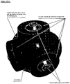
- Fig. 13 and 14 show the application of the adjustable vibration damper according to the invention in wind turbines.
- Modern wind turbines are speed-variable, so that it is often not sufficient to use absorbers or bearings with a fixed natural frequency, which can calm only vibrations of a certain frequency.
- the frequencies are variable.
- Disturbing vibrations, which must be damped with the vibration absorbers arise mainly by the meshing frequencies of gears and also by cogging torques of generators.
- the absorbers and bearings are installed so that their directions of action are aligned in the direction of the resulting vibrations.
- gearboxes mainly torsional excitations occur mainly in the circumferential direction.
- the adaptively adjustable direction of action of the absorber or conical bearing according to the invention is radially and axially possible.
- the ratio between axial and radial Tilgerfrequenz is determined by the cone angle of the elastomeric elements, which are preferably between 30 and 60 °.
- the in Fig. 9A described Tilger is a hybrid Fig. 4 and Fig. 9 , In the Fig. 10-12 described adaptive absorber based on cylindrical elastic double sockets have their preferred direction of action in the radial direction.
- the outer layer can be conical to increase the adjustment range and contain a cavity (3), but can also be as in Fig. 4 be cylindrical and do not contain a cavity. It is essential that this layer lies in a larger diameter range than in Fig. 4 the case is. Thus, the rigidity of this layer is higher and is thus much stiffer than the inner elastomer layer (303). To maximize the adjustment range with the inner layer (303), the outer layer (310) must have a substantially greater rigidity. at Fig. 4 Therefore, the inner cylindrical layer is made longer.
- Fig. 15 shows by way of example a star-shaped arrangement of an acting in all spatial axes adaptive damping system, constructed from the invention Doppelkonus- or multi-cone elements.
- the diversity of the 3D system can be achieved targeted and controlled by different stiffnesses of the individual elements, while the homogeneous aligned in a spatial direction system causes the same stiffness.
- Fig. 16 Another way to increase the force is to axially clamp two conical elastomer elements (801) with force (806) against each other so as to close the gap (802) therebetween.
- Fig. 16A symbolically shows the cone bearing with the gap (802). In Fig. (11B) the gap is partially closed. In Fig. 16 C, the gap is completely closed. The length (803) of the cone bearing is thus doubled. Doubling the length brings due to the resulting ratio of free area to bound surface a very strong increase in spring stiffness.
- the elastomeric elements can be dimensioned according to the known rules. It is also possible to use multilayer elements.
- the force (806) can be applied by means of hydraulic elements, pneumatic elements, spindle drives or even magnetically.
- Fig. 17 shows a 2-layered element.
- a single double cone bearing is pneumatically biased via an air bladder.
- Fig. 18 shows an example of a system consisting of three double cone bearings. These are biased together with a force applying element, in this case, an air bellows. In the system described above, the outer cones are pressed together. But it is also possible, the bias with the inner cones by introducing the force (807) as in Fig.19 drawn to reach.
- a force applying element in this case, an air bellows.
- Fig. 19 exemplifies another embodiment not according to the invention, in the form of a combination of in Fig. 16 to 19 described functions with the in Fig. 1 to 3 described functions.
- the stiffness increases of both systems can thus be multiplied.
- the free space (06) and the gap (802) are closed continuously.
- both stiffness superimposed reinforcing methods There are thus stiffness factors at a reasonable length ratio of approx. 5 possible, giving a stiffness factor when considering the gap (06) of about 18-20 alone.
- a further stiffness factor of approximately 10 is achieved by closing the gap (802), then the entire stiffness factor increases to a value of 180.
- a frequency shift can be achieved by a factor of clearly> 10.
- Fig. 20 shows a storage / Tilgersystem according to the invention, in which the pressure as a function of the excitation frequency can be controlled.
- the pressure as a function of the excitation frequency can be controlled.
- the natural frequency of the absorber or bearing and thus the applied pressure in response to the operating frequency to be canceled and the chamfering position of the absorber to the operating vibration is constantly monitored and controlled.
- Fig. 21 to 23 show by way of example a corresponding application in a Tilger invention, or in a double cone bearing. They consist of the solenoid actuator (1020) in which a coil is wound around a core and out of the stator (1021). Between the two components there is an air gap (1023) which permits a relative movement (1024) and (1025), between (1021) and (1020). These parts correspond to the prior art and are usually used to drive vibrating conveyors. For exact adjustment of the air gap, which is between 0.2 mm to 1.5 mm (max 3 mm), an adjustment device (1022) can be attached.
- the vibration absorbers according to the invention which are equipped with such electro-train pressure magnets, can be operated in all spatial axes.
- axial magnetic drive is compressed in the axial movement (1025), located in (4) pressure medium.
- the medium in (4) is compressible, so that a movement is possible.
- a non-compressible fluid is required to achieve the required spring forces, additional elasticity must be provided.
- This can be in the form of a gas bubble or other spring element which a resilient movement of the pressure medium (in the case of liquid) allows to be performed.
- the attachment of the magnets is preferably carried out in the non-pressurized space.
- the magnet (1020), (1021) may also be as in Fig. 22 shown working within the pressure medium (4).
- a bidirectionally adjustable adaptive damper is shown:
- the systems described so far have a stiffness in the radial plane (XY), which is arranged perpendicular to the axis of the bearing elements.
- a device described below also allows the setting of different stiffnesses in the XY plane, this being done as a static presetting, for example by means of at least one screw or similar devices, which leads to the compression of the respective elastomer layers, or adaptively, for example with a variable hydraulic.
- the static presetting is done by screwing the adjusting screw (2002), whereby the displacer volume (2001) is pressed into the already described system, so that the gap (06-1) closes earlier and thus in the direction of the compressed functional part gives a higher rigidity.
- Fig. 24 the gap (06-01) and (03-01) is already enlarged in the original state, so that the x-direction receives less rigidity before screwing in the set screw (s) (2002).
- a set screw on one side is sufficient.
- two opposing setscrews can be used. If the adjusting screw (s) 2002 are screwed in, the previously lower rigidity in the X direction increases, so that both stiffnesses first align. Upon further screwing in, the rigidity in the X direction increases further, so that it becomes significantly larger than the rigidity in the Y direction.
- the set screw other technical means with the same function can be used.
- the embodiment described serves, for example, as a calibration device to compensate for different stiffnesses of the adjacent construction in the X and Y directions. This corrects frequency deviations of approx. 10% to 30%.
- the adaptive operation of the absorber in two directions is possible.
- the adjustment screw is replaced by a hydraulic connection. An increase in pressure then results in an increase in rigidity.
- the adjustment range of this second adaptivity is about 50% to 80% of the entire adjustment range of the adaptive system.
- the embodiment described can be applied to all the absorbers described in FIGS. 1, 2, 3, 4, 5, 6, 7, 8, 9, 15, 21 and 22.
Description
Die Erfindung betrifft mit elastischen Mittel ausgestatte Lager und sie enthaltende Schwingungstilger mit variabler also adaptiver Steifigkeit, welche dadurch gezielt auf die in der zu dämpfenden Anlage oder Maschine auftretenden unterschiedlichen Erregerfrequenzen eingestellt und angepasst werden können. Die variable Steifigkeit wird dabei durch Einrichten entsprechend platzierter komprimierbarer Freiräume innerhalb des Lagers erreicht, welche gezielt mit Elastomermaterial gefüllt werden können. Die Erfindung betrifft insbesondere solche erfindungsgemäßen adaptiven Schwingungstilger, welche durch unterschiedliche Frequenzen erzeugte Schwingungen zu dämpfen vermögen, in dem die Steifigkeit der elastischen Mittel steuerbar und variable verändert werden kann. Die erfindungsgemäßen Schwingungstilger eignen sich insbesondere für den Einsatz in Windkraftanlagen.The invention relates to equipped with elastic means bearing and vibration absorber containing them with variable so adaptive stiffness, which can be targeted thereby adjusted to the occurring in the system to be damped or machine different exciter frequencies and adjusted. The variable rigidity is achieved by setting appropriately placed compressible free spaces within the bearing, which can be selectively filled with elastomeric material. The invention particularly relates to such adaptive vibration absorbers according to the invention, which are able to dampen vibrations generated by different frequencies, in which the rigidity of the elastic means can be changed controllably and variably. The vibration absorbers according to the invention are particularly suitable for use in wind turbines.
Moderne Windkraftanlagen sind drehzahlvariabel bzw. drehzahlabhängig, so dass es häufig nicht ausreicht, Tilger mit einer festen Eigenfrequenz, welche nur Schwingungen einer bestimmten Frequenz beruhigen können, einzusetzen. Bei drehzahlvariablem Betrieb sind auch die Frequenzen variabel. Störende Schwingungen, die mit den Schwingungstilgern gedämpft werden müssen, entstehen insbesondere in Windkraftanlagen aber auch anderen Anlagen und Maschinen durch die Zahneingriffsfrequenzen von Getrieben und auch durch Rastmomente von Generatoren.Modern wind turbines are speed-variable or speed-dependent, so that it is often not sufficient to use absorbers with a fixed natural frequency, which can calm only vibrations of a certain frequency. In variable-speed operation, the frequencies are variable. Disturbing vibrations, which must be damped with the vibration absorbers, arise in particular in wind turbines but also other systems and machines by the meshing frequencies of gears and also by cogging torques of generators.
Die im stand der Technik bekannten Schwingungstilger werden für eine bestimmte Frequenz verwendet. Bei Maschinen mit variabler Drehzahl und damit unterschiedliche Erregerfrequenz ist es nötig die Schwingungstilger an die jeweilige Frequenz anzupassen.The vibration dampers known in the art are used for a particular frequency. In variable speed machines and thus different excitation frequency, it is necessary to adapt the vibration damper to the respective frequency.
Aus der Physik kommt die Erkenntnis, dass die Frequenzverschiebung die Wurzel aus dem Quotienten der Steifigkeit (gemessen als zu verschiebende Kraft (N/mm) und der Masse ist: ω=√(Federkonstante D/Masse m). Soll zum Beispiel die Frequenz verdoppelt werden, wird die vier fache Steifigkeit benötigt. In der Regel sind sogar größere Spreizungen erforderlich.From physics comes the realization that the frequency shift is the root of the quotient of the stiffness (measured as the force to be shifted (N / mm) and the mass: ω = √ (spring constant D / mass m).) For example, if the frequency doubles four times the rigidity is needed, and usually even larger spreads are required.
So wird zum Beispiel zum Erreichen der vier-fachen Frequenz die 16 fache Steifigkeit benötigt. Bereits der Steifigkeitsfaktor 4 ist mit den bekannten Möglichkeiten nicht erreichbar.For example, to achieve four times the frequency, 16 times the rigidity is needed. Already the
Die
Die
Damit das System überhaupt funktionieren kann, muss der betreffende Innenkegel gegen den betreffenden äußeren Kegel verschoben werden. Das kann mittels eines Linearantriebes (Motor mit Spindel), elektromagnetisch, pneumatisch, hydraulisch oder Mischformen von diesen, gegebenenfalls unter Einbeziehung einer elektronischen Steuerung geschehen. Dabei kann sinnvollerweise das entsprechende konische Federelement (Kegelelement) selbst als Hydraulik- bzw. Pneumatik-Element eingesetzt werden.For the system to work, the inner cone must be moved against the respective outer cone. This can be done by means of a linear drive (motor with spindle), electromagnetic, pneumatic, hydraulic or mixed forms of this, if necessary, involving an electronic control done. It can be usefully used the corresponding conical spring element (cone element) itself as a hydraulic or pneumatic element.
Definitionsgemäß wird unterer einem Konuslager ein Lager verstanden, welches ein Innenkonuselement, und ein Außenkonuselement aufweist, welche durch mindestens eine elastische Schicht miteinander verbunden sind. Beide Konuselement besitzen eine axiale zentrale Bohrung. Eine solches Konuslager wird auch als Einfachkonuslager bezeichnet. Ferner kann auch ein Mehrfachkonuslager eingesetzt werden, welches aus einem besagten Außenkonuselement und einem besagten Innenkonuselement sowie einen oder mehreren Zwischenkonuslementen zusammengesetzt ist, welche wiederum alle durch elastische Schichten miteinander verbunden sind. Definitionsgemäß wird ferner unter einer Anordnung von Konuslagern (Einfach- oder Mehrfach-Konulslagern wie definiert) eine Gruppierung von mindestens zwei Konuslagern (Einfach- oder Merhfach-Konuslager) verstanden, welche gegenüber angeordnet bzw. platziert sind und funktionell in Zusammenhang stehen, wobei die Konuselemente entweder mit ihren breiten Basis, oder mit ihrer schmalen Basis gegenüberstehen, oder aber auch so angeordnet sind, dass die breite Basis des einen Konuselementes der schmalen Basis des gegenüberliegenden Konusteils gegenübersteht. Eine solche Anordnung aus zwei Konuslagern wird nach dieser Erfindung auch als Doppel-Konuslager bezeichnet. Die erfindungsgemäßen Schwingungstilger weisen stets mindestens ein entsprechendes Doppelkonuslager auf, können aber auch mehrere Doppelkonuslager besitzen.By definition, a cone bearing is understood to mean a bearing which has an inner cone element and an outer cone element which are connected to one another by at least one elastic layer. Both cone elements have an axial central bore. Such a cone bearing is also referred to as a single cone bearing. Further, a Mehrfachkonus can be used, which is composed of a said outer cone member and a said inner cone member and one or more Zwischenkonuslementen, which in turn are all interconnected by elastic layers. By definition, an array of conical bearings (single or multiple conical bearings as defined) is also understood to mean a grouping of at least two cone bearings (single or multiple cone bearings) which are located opposite and functionally related, with the conical elements either facing with their broad base, or with their narrow base, or else arranged so that the broad base of one cone element faces the narrow base of the opposite cone part. Such an arrangement of two cone bearings is also referred to as double cone bearings according to this invention. The vibration absorbers according to the invention always have at least one corresponding double cone bearing, but may also have a plurality of double cone bearings.
Gegenstand der Erfindung ist somit ein adaptiver und ggf. aktiver Schwingungstilger mit den Merkmalen des Anspruchs 1. Merkmale dieses Anspruchs betreffend ist dies ein Schwingungstilger mit an die Erregerfrequenz angepasster einstellbarer Steifigkeit, umfassend mindestens ein rotationsymmetrisches unelastisches, vorzugsweise kegliges Innen-Konuselement (01)(108(307)(804) und mindestens ein rotationssymmetrisches unelastisches, vorzugsweise kegliges Außen-Konuselement (02)(202)(805), welches über das Innen-Konuselement gesteckt ist, wobei Innenkonuselement und Außenkonuselement durch eine ein- oder mehrschichtige Elastomerschicht (101)(208)(303)(304)(310) miteinander verbunden sind und jeweils mittig in axialer Richtung eine zylindrische Bohrung aufweisen zur Aufnahme von Befestigungs- oder Verspannungsvorrichtungen, wobei im Bereich der Elastomerschicht (101)(208)(303) (304)(310) entlang der Grenzfläche zum Innenkonus- und / oder Außenkonuselement ein im nicht verspannten Zustand vorhandener entsprechend der Konuselemente geformter vorzugsweise rotationssymmetrischer Freiraum (06)(103)(308)(802) vorgesehen ist, der teilweise oder vollständig die Grenzfläche zwischen Außenkonus-, und Innenkonuselement einnehmen kann, und das Innenkonuselement und / oder Außkonuselement in axialer Richtung durch technische Mittel und Vorrichtungen im oder außerhalb des Lagers beispielsweise mechanischer oder hydraulischer oder magnetischer Art verschiebbar ist. Hierdurch durch Kompression und teilweise Verdrängung der in den konischen Elementen vorhandenen Elastomerschicht in den besagten Freiraum teilweise oder ganz geschlossen, wodurch die Steifigkeit des Lagers oder Lagersystems entsprechend der zu dämpfenden Erregerfrequenz variiert und angepasst werden kann. Vorzugsweise besitzt besagter Freiraum (06)(103)(308)(802), der an der Grenzfläche der Elastomerschicht (101)(208)(303)(304)(310) gebildet wird, eine bauchige, konkave oder konvexe oder anderweitig geometrische Form, was durch entsprechende Gestaltung der Elastomerschicht aber auch des konischen Innen- und / oder Außenkegels in diesem Bereich erreicht wird. Um die gewünschte Adaptivität an die Steifigkeit zu erhalten, sollte der konusförmige Freiraum (06)(103)(308)(802) entlang der Grenzfläche zwischen Elastomerschicht (101)(208)(303)(304)(310) und Innenkegel oder zwischen Elastomerschicht und Außenkegel eine Länge aufweisen, die 20 bis 80%, vorzugsweise 40 - 70% der Länge der Kegel oder der Länge der Elastomerschicht zwischen den Kegeln entspricht. Ebenso sollte der konusförmige Freiraum (06)(103)(308)(802) entlang der Grenzfläche zwischen Elastomerschicht und Innenkegel oder zwischen Elastomerschicht und Außenkegel eine Dicke aufweisen, die 5 - 30%, vorzugsweise 10 - 20% der Dicke der Elastomerschicht zwischen den Kegeln entspricht. Durch diese Geometrien können Steifigkeitsfaktoren von mindestens 4, vorzugsweise > 4, insbesondere zwischen 10 und 150 erzielt werden, was eine Frequenzverschiebung (Erregerfrequenz) um den Faktor 3 - 20, vorzugsweise 3 - 10 zur Folge hat.The subject matter of the invention is therefore an adaptive and optionally active vibration absorber having the features of
Durch die Lager kann die Steifigkeit vor allem in axialer Richtung (z-Achse) aber auch in radialer Richtung (x, y) adaptiert und variabel eingestellt werden, wobei die radiale Steifigkeit in bei einem festen Konuswinkel nicht so stark beeinflussbar ist wie in axiale Richtung und sich ohne weitere Maßnahmen mehr oder weniger gleichmäßig auf die x- und y-Richtung verteilt. Um eine unterschiedliche radiale x,y-Steifigkeit zu erreichen, kann wie in einer weiteren Ausführungsform gezeigt, die konusförmige Elstomerschicht (101)(208)(303)(304)(310) an einer oder mehreren Stellen einen direkten Zugang (2002) für mechanische oder hydraulische Mittel besitzen, wobei deren Zugang so platziert ist, dass in radialer (x,y) Richtung eine adaptierbare variable Steifigkeit erzielt wird, welche sich unterschiedlich in x- und y-Richtung auswirkt.The stiffness can be adapted and variably adjusted by the bearings, above all in the axial direction (z-axis) but also in the radial direction (x, y), wherein the radial stiffness in is not as strongly influenced at a fixed cone angle as in the axial direction and distributed without further action more or less evenly in the x and y direction. In order to achieve a different radial x, y stiffness, as shown in another embodiment, the cone-shaped elastomeric layer (101) (208) (303) (304) (310) may have direct access (2002) at one or more locations have mechanical or hydraulic means, wherein the access is placed so that in the radial (x, y) direction an adaptable variable stiffness is achieved, which varies in the x and y direction.
Die Konuslager können zusätzlich weitere Elastomerschichten und weitere Konuselemente aufweisen. Ferner kann der Konuswinkel α eines Konuselements kleiner sein als der Konuswinkel eines anderen Konuselements, so dass durch die unterschiedlichen Kegelwinkel radiale und axiale Schwingungen unterschiedlich beeinflusst werden können.The conical bearings may additionally comprise further elastomer layers and further conical elements. Furthermore, the cone angle α of a cone element can be smaller than the cone angle of another cone element, so that radial and axial vibrations can be influenced differently by the different cone angles.
Es ist ferner vorteilhaft, auch weitere Freiräume, die durch Elastomermaterial ausgefüllt werden können, im Lager einzurichten, was zur deutlichen Variabilität der Steifigkeit sowie Erhöhung des Steifigkeitsfaktors führen kann. In einer Ausführungsform der Erfindung können beispielsweise zwei gegenüber positionierte Konuslager so eng zueinander angeordnet sein, dass ein Spalt (802) im unverspannten Zustand vorliegt. Dieser Spalt kann durch Verspannen der Konuselemente des Lagers teilweise oder ganz verschlossen werden, so dass hierdurch die Steifigkeit zusätzlich beeinflusst werden kann (
In einer üblichen Ausführungsform weist das Konuslager oder die Anordnung von Konuslagern zwei Konuslager unter Bildung eines Doppelkonuslagers auf, welche gegenüber mit ihrer breiten und / oder kurzen Konusbasis angeordnet sind. Vorzugsweise zwischen den beiden Konuslagern, aber auch an anderen Stellen des Lagers oder außerhalb des Lagers befindet sich erfindungsgemäß eine mechanische, pneumatische, hydraulische oder magnetische Vorrichtung, die es ermöglicht, dass die jeweiligen frei beweglichen Innenkonuselemente oder Außenkonuselemente der beiden Konuslager axial vorzugsweise gegen die jeweiligen fixierten Außenkonuslemente bzw. Innenkonuselemente verschoben werden können, und somit Elastomermaterial in die besagten Freiräume der Lager gepresst werden kann. Die axiale Verschiebung der Konuselemente kann dabei durch hydraulische, pneumatische, mechanische oder magnetische Mittel aktiv oder passiv erfolgen. In einer besonderen Ausführungsform erfolgt die axiale Verschiebung der funktionellen Konuselemente durch ein oder mehrere Flachmagnete vorzugsweise durch aktive Ansteuerung, wie unten näher beschrieben.In a common embodiment, the conical bearing or assembly of cone bearings has two cone bearings forming a double cone bearing, which are arranged opposite to their broad and / or short cone base. Preferably, between the two cone bearings, but also at other locations of the bearing or outside of the bearing according to the invention is a mechanical, pneumatic, hydraulic or magnetic device that allows the respective freely movable inner cone elements or outer cone elements of the two cone bearings axially preferably against the respective fixed Außenkonuslemente or inner cone elements can be moved, and thus elastomeric material can be pressed into the said free spaces of the bearing. The axial displacement of the cone elements can be carried out actively or passively by hydraulic, pneumatic, mechanical or magnetic means. In a particular embodiment, the axial displacement of the functional cone elements by one or more flat magnets is preferably carried out by active control, as described in more detail below.
Es ist vorteilhaft die Konuslager oder Anordnungen von Konuslagern mit Sensoren sowie gegebenenfalls elektronische computergesteuerte Einrichtungen auszustatten, welche eine Veränderung der Erregersequenz messen und aus der gemessenen Veränderung der Erregerfrequenz eine automatische Anpassung der Steifigkeit durch axiale Verschiebung der entsprechenden Konuselemente bewirken. Die entsprechende technische Ausrüstung ist im Stand der Technik prinzipiell bekannt.It is advantageous to equip the conical bearings or arrangements of conical bearings with sensors and optionally electronic computer-controlled devices which measure a change in the excitation sequence and effect an automatic adaptation of the stiffness by axial displacement of the corresponding conical elements from the measured change in the excitation frequency. The corresponding technical equipment is known in principle in the prior art.
Gegenstand ist ferner ein Doppelkonuslager, bei welchem zwei Einfach- oder Merfachkonuslager, wie oben oder in den Ansprüchen definiert, mit ihrer breiten oder schmalen Basis gegenüber angeordnet sind, die Innenkonuselemente (01)(108(307)(804) über eine Elastomerschicht (1) mit einer axialen zylindrischen Hülse (13) um die mittige axiale Bohrung verbunden sind, und Druckmittel vorhanden sind, mittels derer die betreffenden Konuselemente der Konuslager in axialer Richtung bewegt werden können, wodurch die besagten Freiräume (06)(103)(308) in den Konussen mit Elastomermaterial gefüllt werden und somit die Steifigkeit des Lagers variiert werden kann. In einer besonderen Ausführungsform befindet sich vorzugsweise zwischen den beiden gegenüberliegenden Konuslagern eine Druckkammer, welche mittels mechanischer, hydraulischer, pneumatischer oder magnetischer Mittel mit Druck beaufschlagt werden kann, so dass die jeweiligen frei beweglichen Innenkonuselemente axial auseinander und gegen ihr jeweiliges festes Außenkonuselement gedrückt werden können und somit Elastomermaterial (101)(208)(303) (304)(310) in die besagten Freiräume (06)(103)(308) der Lager gepresst wird. Die Erfindung umfasst auch solche Lager, bei denen freibewegliche Außenkonuselemente gegen festmontierte Innenkonuselemente verschoben werden können.The subject matter is further a double cone bearing, in which two single or multiple cone bearings, as defined above or in the claims, are arranged with their wide or narrow base opposite, the inner cone elements (01) (108 (307) (804) via an elastomer layer (1 ) are connected to an axial cylindrical sleeve (13) about the central axial bore, and pressure means are provided by means of which the respective cone elements of the cone bearings can be moved in the axial direction, whereby said free spaces (06) (103) (308) in In one particular embodiment, a pressure chamber is preferably located between the two opposing conical bearings, which can be pressurized by means of mechanical, hydraulic, pneumatic or magnetic means, so that the pressure can be applied to the cones respective freely movable inner cone elements axially apart and geg and their elastomeric material (101) (208) (303) (304) (310) is pressed into said free space (06) (103) (308) of the bearings. The invention also includes such bearings in which freely movable outer cone elements can be displaced against firmly mounted inner cone elements.
Gegenstand der Erfindung sind Schwingungstilger umfassend eine Tilgermasse und mindestens ein Doppelkonuslager, wie oben und folgend beschrieben. und in den Merkmalen des Anspruchs 1 definiert. Ein erfindungsgemäßer Schwingungstilger kann aus einem, zwei, drei oder mehreren, vorzugsweise funktionell zusammenwirkenden Doppelkonuslagern aufgebaut sein.The invention relates to vibration absorbers comprising a damping mass and at least one double cone bearing, as described above and following. and defined in the features of
Die entsprechenden Konuslager oder Anordnungen von Konuslagern, insbesondere Doppelkonuslagern, sowie die entsprechenden mit diesen Lagern ausgestatten Schwingungstilger können insbesondere zur Dämpfung von Schwingungen in Anlagen und Maschinen mit variabler Drehzahl und / oder Erregerfrequenz, insbesondere in Windkraftanlagen eingesetzt werden.The corresponding cone bearings or arrangements of conical bearings, in particular double cone bearings, and the corresponding equipped with these bearings vibration absorber can be used in particular for damping vibrations in systems and machines with variable speed and / or excitation frequency, especially in wind turbines.
Gegenstand der Erfindung sind somit auch Windkraftanlagen, in denen die erfindungsgemäßen Schwingungstilger im Bereich der Rotornabe, der Rotorblätter, des Getriebestranges oder des Turmes angeordnet sind, wobei vorzugsweise 4 - 48, vorzgsweise 6 - 36 Schwingungstilger vorzugsweise im Bereich der Rotornabe vorzugsweise symmetrisch angeordnet sind, um Vibrationen durch Drehzahländerungen von Rotor und / oder Getriebe zu reduzieren.The invention thus also relates to wind turbines in which the vibration absorbers according to the invention are arranged in the region of the rotor hub, the rotor blades, the gear train or the tower, preferably 4-48, preferably 6-36, vibration absorbers preferably being arranged symmetrically in the area of the rotor hub. to reduce vibration due to speed changes of the rotor and / or gearbox.
Das Erfindungsprinzip lässt sich auch prinzipiell auf Tilger und Lager in diesen Tilgern anwenden, welche nicht nur die entsprechenden beschriebenen Doppel- oder Mehrfach-Konuselementen betreffen, sondern auch auf entsprechende Tilger und Lager auf Basis entsprechend ausgestatteter zylindrischer elastischer Doppel- oder Mehrfachbuchsen mit entsprechenden Freiräumen, Spalten, Hohlräumen, welche entsprechend durch Verschieben von inneren und äußeren zylindrischen Buchsen und damit verursachtes Einpressen von Elastomermaterial ganz oder vollständig geschlossen werden können, womit die Steifigkeit adaptiv und geregelt eingestellt werden kann (
Die Beschreibung betrifft somit auch ein adaptives Buchsenlager oder eine Anordnung von Einfach- oder Mehrfachbuchsenlagern mit an die Erregerfrequenz angepasster Steifigkeit, im Wesentlichen umfassend mindestens ein rotationsymmetrisches unelastisches, vorzugsweise zylindrisches Innen-Buchsenelement und mindestens ein rotationssymmetrisches unelastisches, vorzugsweise zylindrisches Außen-Buchsenelement, welches passend über das Innen-Buchsenelement gesteckt ist, wobei Innenbuchsenelement und Außenbuchsenelement durch eine ein- oder mehrschichtige Elastomerschicht mit einander verbunden sind und jeweils mittig in axialer Richtung eine zylindrische Bohrung aufweisen zur Aufnahme von Befestigungs- oder Verspannungsvorrichtungen, wobei im Bereich der Elastomerschicht entlang der Grenzfläche zum Innenbuchsen- und / oder Außenbuchsenelement ein im nicht verspannten Zustand vorhandener entsprechend der Buchsenelemente geformter rotationssymmetrischer Freiraum vorgesehen ist, der teilweise oder vollständig die Grenzfläche zwischen Außenbuchsen-, und Innenbuchsenelement einnehmen kann, und das Innenbuchsenelement und / oder Außbuchsenelement in axialer Richtung durch technische Mittel und Vorrichtungen im Lager verschiebbar ist, so dass die beiden zylindrischen Buchsenelemente verspannt werden, und dabei der besagte Freiraum durch Kompression und teilweise Verdrängung der vorhandenen Elastomerschicht zwischen den Buchsenelementen teilweise oder ganz geschlossen wird, wodurch die Steifigkeit des Lagers oder Lagersystems entsprechend der zu dämpfenden Erregerfrequenz variiert und angepasst werden kann.The description thus also relates to an adaptive bushing bearing or an arrangement of single or multiple bushings with stiffness adapted to the excitation frequency, essentially comprising at least one rotationally symmetric inelastic, preferably cylindrical, inner bushing element and at least one rotationally symmetric inelastic, preferably cylindrical, outer bushing element which fits is inserted over the inner socket member, said inner sleeve member and outer sleeve member are connected by a single or multi-layer elastomer layer with each other and each have centrally in the axial direction a cylindrical bore for receiving fastening or bracing devices, wherein in the elastomer layer along the interface to Innenbuchsen- and / or outer sleeve member is provided in a non-strained state according to the socket elements shaped rotationally symmetric free space, the teilwei se or completely can take the interface between Außenbuchsen-, and inner sleeve member, and the inner sleeve member and / or outer sleeve member in the axial direction by technical means and devices in the bearing is displaceable, so that the two cylindrical sleeve elements are braced, and thereby the said space by compression and partial displacement of the existing elastomer layer between the female elements is partially or completely closed, whereby the stiffness of the bearing or storage system can be varied and adjusted according to the frequency to be damped to be damped.
Die erfindungsgemäßen Tilger wie folgend näher beschrieben, eigenen sich, wie bereits gesagt, vor allem für ihren Einsatz in Windkraftanlagen. Weitere Einsatzbereiche sind der Fahrzeugbereich insbesondere Drehgestelle und Waggons von Eisenbahnfahrzeugen, landwirtschaftliche Maschinen, Baufahrzeuge, Krane Schiffe Im Antriebsbereich und in der gesamten Schiffshaut und an Anbautreilen un inneren Einrichtungen, insbesondere in Personenschiffen.The absorbers of the invention as described in more detail below, own, as already said, especially for their use in wind turbines. Further fields of application are the vehicle sector, in particular bogies and wagons of railway vehicles, agricultural machines, construction vehicles, cranes, ships in the drive area and in the entire ship's skin and on cultivation parts and internal equipment, in particular in passenger ships.
Es werden hier adaptive Tilger und Lager beschrieben, bei denen die Eigenfrequenz des Federmassesystems durch unterschiedliche Möglichkeiten eingestellt werden kann. Durch die besondere Konstruktion mit entsprechenden positionierten Freiräumen und Spalten können so erfindungsgemäß Steigerungen der Steifigkeit um denn Faktor 10 - 150 erreicht werden, was einen ansprechbaren zu dämpfenden Frequenzbereich etwa um den Faktor 3 - 12 entspricht, verglichen mit einem herkömmlichen elastischen Lager oder Tilger des Standes der Technik. Das Lager / Tilgersystem wird in der Regel als Kernstück von Schwingungstilgern, die in einem breiten Frequenzbereich arbeiten sollen, eingesetzt.Here, adaptive absorbers and bearings are described in which the natural frequency of the spring system can be adjusted by different possibilities. Due to the special construction with correspondingly positioned free spaces and gaps, according to the invention increases in rigidity can be achieved by a factor of 10 to 150, which corresponds to an addressable frequency range to be damped by a factor of 3 to 12 compared with a conventional elastic bearing or absorber of the prior art of the technique. The bearing / absorber system is usually used as the core of vibration absorbers, which are to work in a wide frequency range.
Erfindungsgemäß ist es möglich, erfindungsgemäßen einstellbaren Schwingungstilger auch aktiv zu betreiben, also mit Aufbringen einer Kraft in Erregerfrequenz. Der Vorteil dabei ist, dass ein größerer Schwingungstilger Effekt mit gleicher Masse oder ein gleicher Effekt mit deutlich geringerer Masse erzielt werden kann. Gegenstand der Erfindung ist somit auch ein entsprechender adaptiver und aktiver Schwingungstilger, welcher auch aktiv betrieben werden kann.According to the invention, it is possible to actively operate adjustable vibrating damper according to the invention, that is, by applying a force in excitation frequency. The advantage of this is that a larger vibration damper effect with the same mass or the same effect can be achieved with significantly less mass. The invention thus also relates to a corresponding adaptive and active vibration absorber, which can also be actively operated.
Aktive Schwingungstilger werden in der Regel mit Tauch-Spulensystemen angetrieben. Bei unserem System, das für kleine Amplituden ausgelegt ist werden Elektro-Zug-Druck Magnete verwendet. Im Gegensatz zu Tauch Spulen lassen diese zwar nur geringe Federwege zu, können jedoch deutlich höhere Kräfte bewirken.Active vibration absorbers are usually powered by immersion coil systems. In our system, which is designed for small amplitudes, electro-train-pressure magnets are used. In contrast to immersion coils, these allow only small spring travel, but can cause significantly higher forces.
Eine Aktivierung der erfindungsgemäßen Tilger kann beispielsweise durch zusätzlich angeordnete Elektromagneterreicht werden. Dazu hat sich überraschenderweise herausgestellt, dass Flachmagnete, insbesondere flache Elektro-Zug-Druckmagnete, hierfür bestens geeignet sind im Gegensatz zu den bisher nach dem Stand der Technik bekannten Tauchspulen. Der Vorteil der Flachmagnete ist, dass diese auf kleinem Bauchraum große Kräfte entwickeln können und auch kostengünstiger und weniger sensibel als Tauchspulen sind.Activation of the absorber according to the invention can be achieved, for example, by additionally arranged electromagnets. For this purpose, it has surprisingly been found that flat magnets, in particular flat electro-train pressure magnets, for this purpose are ideally suited in contrast to the previously known in the prior art plunger coils. The advantage of flat magnets is that they can develop large forces on a small abdominal cavity and are also less expensive and less sensitive than immersion coils.
Die erfindungsgemäßen Tilger und Lager in diesen Tilgern können prinzipiell wie folgt geregelt und gesteuert werden:
- Adaptives System: (i) Steuerung des adaptiven Tilgersystems: bei diesem System wird der Druck abhängig von der gewünschten Frequenz über ein Tilgerkennfeld gesteuert. Diese Frequenz ist zum Beispiel von der Drehzahl abhängig. Somit wird der Druck in direkter Abhängigkeit von der Drehzahl gesteuert. (ii) Regelung des adaptiven Tilgersystems: bei diesem System wird ständig die anregende Schwingung und die Schwingung des Tilgers in Phase und Betrag mit einem Beschleunigungs-Sensor gemessen und die Differenz der beiden Phasen Winkel (Phasenverschiebung) ermittelt. Durch die Phasenverschiebung lässt sich das Eigenfrequenzverhalten des Tilgers so bestimmen, dass die Eigenfrequenz des Tilgers der Störfrequenz angepasst wird. Ist die Phasenverschiebung kleiner als ein gewünschter Sollwert, so wird der Hydraulik-bzw. Gas-Druck des Systems erhöht. Ist die Phasenverschiebung größer als der Sollwert so wird der Druck verringert. Diese Abläufe geschehen in kleinen Stufen, so dass ständig nachgeregelt wird. Zwischen Tilger und Hydraulikaggregat sind dazu beispielsweise zwei Ventile (1026) (1027) geschaltet. Zur Erhöhung des Druckes wird das Einlassventil (1026) und zur Senkung des Drucks das Auslassventil (1027) kurzzeitig geöffnet und der Phasenwinkel gemessen. Der Vorgang wird so oft wiederholt, bis der richtige Phasenwinkel (Sollwert) erreicht ist. Mit dieser Regelung können eventuelle Amplituden-, Temperatur- und Frequenzabhängigkeiten oder andere Veränderungen des Tilgers ausgeglichen werden. Außerdem kann sich der Tilger/das Lager Änderungen der anregenden Schwingung anpassen. Wenn sich, z.B., die anregende Schwingung mit der Drehzahl in der Frequenz oder Amplitude ändert, kann die Regelung den Tilger/das Lager so verstellen, dass der vorgegebene Sollwert erreicht wird und so der Tilger/das Lager optimal wirkt. Das zu beruhigende System kann mit einem oder mehreren Tilgern bestückt sein. Ist das anregende System mit mehreren Tilgern bestückt, dann kann ein Tilger geregelt werden und die anderen Tilger sind hydraulisch, pneumatisch oder elektrisch parallel geschaltet und sehen die gleiche Vorspannung wie der geregelte Tilger, müssen also nicht separat geregelt werden. Wird ein System durch viele Tilger beruhigt, dann kann auch jeder Tilger mit eigener Regelung ausgestattet sein.
- Aktives System (
Abb. 21 ): Parallel zur Regelung des adaptiven Systems wird ein Magnet-Erreger (1020) und (1021) zwischen Schwingungstilger und anregendem System geschaltet und übt damit zusätzliche Kräfte zwischen Schwingungstilger und anregendem System aus. Er wird vorzugsweise bei der ermittelten Störfrequenz betrieben. Die Kraftamplitude und die Phasenverschiebung zwischen der Kraft des Magnet-Erregers und der Schwingung des anregenden Systems muss mittels eines geschlossenen Regelkreises ermittelt werden. Dabei wird das anregende System durch einen Beschleunigungssensor beobachtet und die Kraftamplitude und die Phasenverschiebung so lange geändert, bis der Beschleunigungssensor anzeigt, dass die Schwingung des anregenden Systems minimal ist. Da die Eigenfrequenz des Tilgers durch den adaptiven Regelkreis der Störfrequenz angepasst wird, und der Magnet-Erreger auch bei dieser Frequenz arbeitet, geht nur ein kleiner Kraftanteil des Magnet-Erregers durch die interne Tilger-/Lagerdämpfung verloren. Der verbleibende, größere Anteil kann für die Reduzierung der Systemschwingungen genutzt werden. Alternativ zu dem hydraulischen oder pneumatischen System kann man auch ein elektrischer Linear -Stellmotor eingesetzt werden.
- Adaptive system: (i) Adaptive damping system control: in this system, the pressure is controlled via a damping map depending on the desired frequency. This frequency depends, for example, on the speed. Thus, the pressure is controlled in direct dependence on the speed. (ii) adaptive absorber system control: in this system, the exciting vibration and the vibration of the absorber in phase and magnitude are continuously measured with an acceleration sensor, and the difference of the absorber two phase angle (phase shift) determined. Due to the phase shift, the natural frequency behavior of the absorber can be determined so that the natural frequency of the absorber is adapted to the interference frequency. If the phase shift is smaller than a desired setpoint, then the hydraulic or. Gas pressure of the system increased. If the phase shift is greater than the setpoint, the pressure is reduced. These processes are done in small steps, so that constantly readjusted. For example, two valves (1026) (1027) are connected between the absorber and the hydraulic power unit. To increase the pressure, the inlet valve (1026) and to lower the pressure, the outlet valve (1027) is opened briefly and measured the phase angle. The process is repeated until the correct phase angle (setpoint) is reached. This control compensates for any amplitude, temperature and frequency dependencies or other changes in the absorber. In addition, the absorber / bearing can adapt to changes in the stimulating vibration. If, for example, the exciting vibration changes in speed or frequency with the speed, the control can adjust the damper / bearing so that the predetermined set point is reached and thus the damper / bearing acts optimally. The system to be calmed can be equipped with one or more absorbers. If the stimulating system is equipped with several absorbers, then one absorber can be regulated and the other absorbers are connected hydraulically, pneumatically or electrically in parallel and see the same preload as the regulated absorber, ie they do not have to be regulated separately. If a system is calmed by many absorbers, then each absorber can be equipped with its own regulation.
- Active system (
Fig. 21 ): In parallel to the adaptive system control, a magnet exciter (1020) and (1021) is interposed between the vibration absorber and the stimulating system, thus exerting additional forces between the vibration absorber and the stimulating system. It is preferably operated at the determined interference frequency. The force amplitude and the phase shift between the force of the magnet exciter and the vibration of the exciting system must be determined by means of a closed loop. The exciting system is monitored by an acceleration sensor, and the force amplitude and phase shift are changed until the acceleration sensor indicates that the vibration of the exciting system is minimal. Since the natural frequency of the absorber is adjusted by the adaptive control circuit of the disturbing frequency, and the magnet exciter operates at this frequency, only a small share of force of the magnet exciter is lost by the internal absorber / bearing damping. The remaining, larger proportion can be used to reduce the system vibrations become. As an alternative to the hydraulic or pneumatic system, it is also possible to use an electric linear positioning motor.
Die Schwingungstilger und Lager zeichnen sich zusammengefasst, wie folgt aus:
- Steifigkeitsverstärkung durch Schließen des Spaltes, Hohlraumes oder Freiraumes
- Wirksam in radialer und axialer Richtung
- Erhöhung des Steifigkeit maximal um den Faktor 10 - 150, und entsprechend angepasste Erhöhung der Erregerfrequenz maximal um den Faktor 3 - 20.
- Ansteuerbar durch hydraulische, pneumatische oder mechanische Systeme
- Einsatz in Maschinen, in denen eine variable Steifigkeit benötigt wird: z.B. für Radsatzführung bei Schienenfahrzeugen, Windkraftanlagen, insbesondere im Bereich des Getriebes , der Rotornabe, der Gondel und des Turmes. Hierfür werden beispielsweise 4 - 48 entsprechende erfindungsgemäße Tilger, vorzugsweise symmetrisch um die Rotornabe, das Getriebe oder den Turm angeordnet, wobei in einer besonderen Ausführungsform Dualeinheiten von Tilgern, wie z.B. in
Abb. 8 abgebildet, zum Einsatz kommen können. - Bei all diesen Systemen, insbesondere bei Windkraftanlagen, wird der Druck als Funktion der Anregungsfrequenz geregelt. Um die Toleranz, Temperatur- und Alterungseigenschaften der Elastomere auszugleichen, wird die Eigenfrequenz des Tilgers und damit der aufzubringende Druck in Abhängigkeit von der zu tilgenden Betriebsfrequenz und der Phasenlage des Tilgers zur Betriebsschwingung ständig überwacht und geregelt. Dies kann durch elektronische Sensoren computergesteuert manuell oder automatisch durch an sich im Stand der Technik vorhandene Mittel erfolgen. Insbesondere bei Windkraftanlagen können dadurch unterschiedlich auftretende variable Schwingungen permanent gedämpft werde, wodurch auch Belästigungen durch Geräusche und Vibrationen in der Anlage stark reduziert und sogar eliminiert werden können.
- Rigidity enhancement by closing the gap, cavity or clearance
- Effective in the radial and axial directions
- Increasing the rigidity by a maximum of a factor of 10 - 150, and correspondingly increasing the excitation frequency by a factor of 3 - 20 at most.
- Can be controlled by hydraulic, pneumatic or mechanical systems
- Use in machines where a variable rigidity is required: eg for wheel set guidance in rail vehicles, wind turbines, especially in the area of the gearbox, the rotor hub, the nacelle and the tower. For this purpose, for example, 4-48 corresponding Tilger invention, preferably arranged symmetrically about the rotor hub, the gear or the tower, wherein in a particular embodiment, dual units of Tilgern, such as in
Fig. 8 shown, can be used. - In all these systems, especially in wind turbines, the pressure is regulated as a function of the excitation frequency. To compensate for the tolerance, temperature and aging properties of elastomers, the natural frequency of the absorber and thus the pressure to be applied in response to the operating frequency to be canceled and the phase position of the absorber to the operating vibration is constantly monitored and controlled. This can be done by computer-controlled electronic sensors manually or automatically by means known in the art. Especially in wind turbines different occurring variable vibrations can thus be permanently damped, which also harassment by noise and vibration in the system can be greatly reduced and even eliminated.
Kurze Beschreibung der im Text, in den Ansprüchen und in den Abbildungen verwendeten Bezugsgrößen:
- 01
- Innenkegel/Innenkonus
- 02
- Außenkegel/Außenkonus
- 03
- Kegelige Elastomerschicht oben
- 04
- Kegelige Elastomerschicht unten
- 05
- über gesamte Länge geschlossene Elastomerschicht
- 06
- Freiraum
- 1
- Elastomerschicht zylindrisch
- 2
- Elastomerschicht kegelig
- 3
- Zur Versteifung aufzufüllender Freiraum
- 4
- Druckkammer
- 5
- Druckanschluss
- 6
- Befestigung
- 7
- Tilgermasse
- 8
- Zwischen kegel
- 9
- Außenkegel
- 10
- Blech kurz
- 11
- Länge der kurzen Kegel
- 12
- Länge der langen Kegel
- 13
- Innenhülse
- 101
- Konusschicht
- 102
- Schiebeelement
- 103
- Zur Versteifung auszufüllender Bereich
- 104
- Druckkammer
- 105
- Druckanschluss
- 106
- Befestigung
- 107
- Masse
- 108
- Innenkegel
- 109
- äußerer Schiebebereich
- 110
- Länge kurze Kegel
- 111
- Länge lange Kegel
- 112
- Membran
- 202
- Außenkonus
- 203
- Druckplatte
- 204
- Membran Hohlraum
- 205
- Druckanschluss
- 206
- Druckelastomer
- 207
- Axialklemmung
- 208
- Konische Elastomerschicht
- 209
- Einstellschraube mit Innensechskant
- 210
- Verbindungsschraube
- 301
- Masse
- 302
- Befestigung
- 303
- Elastomerschicht innen
- 304
- Elastomerschicht außen
- 305
- Druckraum
- 306
- Druckanschluss
- 307
- Kegel innen
- 308
- Freiraum
- 309
- Zwischenkegel
- 310
- Zylindrische bis leicht konische Außenschicht
- 401
- Druckstück
- 402
- Schiebeelement
- 403
- Elastomer-Verdrängungsvolumen
- 404
- Elastomer
- 405
- Innenbuchse
- 406
- Hydraulikelement
- 501
- Ringförmiger Kompressionsraum
- 502
- Elastomer
- 503
- Innenbuchse
- 504
- Ausdehnungsform vergrößert dargestellt
- 505
- Außenbuchse
- 601
- Endblech Ring
- 602
- Achse mit Einschnürung
- 701
- Tilger Anordnung an Rotorwelle
- 702
- Tilger Anordnung an Getriebe
- 703
- Tilger Anordnung an schnelllaufenden Generator und am mittel schnelllaufenden Generator
- 704
- Tilger Anordnung am Maschinenträger
- 705
- Tilger Anordnung an Nebenaggregaten
- 706
- Tilger Anordnung am Turm
- 707
- Tilger Anordnung an Rotornabe
- 708
- Tilger Anordnung am Langsam Laufenden Generator
- 709
- Tilger mit zwei Funktionsteilen und einer gemeinsamen Masse am Generator befestigt
- 710
- Tilger Anordnung an- oder in den Rotorblättern
- 801
- Elastomerschicht
- 802
- zu schließender Spalt
- 803
- Länge der Elastomerschicht
- 804
- innerer Kegel
- 805
- äußerer Kegel
- 810
- Luftbalg zum Aufbringen der axialen Kraft
- 811
- Zugplatte für Luftbalg
- 812
- Befestigungselement
- 813
- Befestigungs- Schraube
- 814
- Maschinen Anschluss
- 1020
- Elektromagnet Aktuator
- 1021
- Elektromagnet Stator
- 1022
- Befestigung-und Einstellschrauben für Elektro Magnet
- 1023
- Luftspalt
- 1024
- Magnet Kraftrichtung radial
- 1025
- Magnet Kraftrichtung axial
- 1026
- Einlassventil
- 1027
- Auslassventil
- 2001
- komprimierbares Volumen der Elastomerschicht
- 2002
- Vorrichtung zum Komprimieren der Schicht 2001 (z.B. Stellschraube, Hydraulik)
- 01
- Internal taper / inner cone
- 02
- Outer cone / outer cone
- 03
- Tapered elastomer layer above
- 04
- Tapered elastomeric layer below
- 05
- Closed over the entire length elastomer layer
- 06
- free space
- 1
- Elastomer layer cylindrical
- 2
- Elastomer layer conical
- 3
- For stiffening aufzufüllender free space
- 4
- pressure chamber
- 5
- pressure connection
- 6
- attachment
- 7
- absorber mass
- 8th
- Between cones
- 9
- outer cone
- 10
- Sheet short
- 11
- Length of the short cone
- 12
- Length of the long cones
- 13
- inner sleeve
- 101
- cone layer
- 102
- sliding element
- 103
- For stiffening area to be filled
- 104
- pressure chamber
- 105
- pressure connection
- 106
- attachment
- 107
- Dimensions
- 108
- inner cone
- 109
- outer sliding area
- 110
- Length short cones
- 111
- Length long cones
- 112
- membrane
- 202
- outer cone
- 203
- printing plate
- 204
- Membrane cavity
- 205
- pressure connection
- 206
- pressure elastomer
- 207
- Axialklemmung
- 208
- Conical elastomer layer
- 209
- Adjusting screw with hexagon socket
- 210
- connecting screw
- 301
- Dimensions
- 302
- attachment
- 303
- Elastomer layer inside
- 304
- Elastomer layer outside
- 305
- pressure chamber
- 306
- pressure connection
- 307
- Cone inside
- 308
- free space
- 309
- between the plug
- 310
- Cylindrical to slightly conical outer layer
- 401
- Pressure piece
- 402
- sliding element
- 403
- Elastomer displacement
- 404
- elastomer
- 405
- inner bushing
- 406
- hydraulic element
- 501
- Annular compression space
- 502
- elastomer
- 503
- inner bushing
- 504
- Expansion form shown enlarged
- 505
- outer bush
- 601
- End plate ring
- 602
- Axle with constriction
- 701
- Tilger arrangement on rotor shaft
- 702
- Absorber arrangement on gearbox
- 703
- Tilger arrangement on high-speed generator and on medium high-speed generator
- 704
- Tilger arrangement on the machine carrier
- 705
- Absorber arrangement on ancillary units
- 706
- Tilger arrangement at the tower
- 707
- Tilger arrangement on rotor hub
- 708
- Tilger arrangement on slow running generator
- 709
- Tilger with two functional parts and a common mass attached to the generator
- 710
- Tilger arrangement on or in the rotor blades
- 801
- elastomer layer
- 802
- gap to be closed
- 803
- Length of the elastomer layer
- 804
- inner cone
- 805
- outer cone
- 810
- Air bellows for applying the axial force
- 811
- Pull plate for air bellows
- 812
- fastener
- 813
- Fixing screw
- 814
- Machine connection
- 1020
- Electromagnet actuator
- 1021
- Electromagnet stator
- 1022
- Fixing and adjusting screws for electric magnet
- 1023
- air gap
- 1024
- Magnet direction of force radial
- 1025
- Magnet direction of force axial
- 1026
- intake valve
- 1027
- outlet valve
- 2001
- compressible volume of the elastomer layer
- 2002
- Device for compressing the layer 2001 (eg adjusting screw, hydraulic)
Im Folgenden werden mehrere typische Ausführungsformen des erfindungsgemäßen einstellbaren Schwingungstilgers sowie andere Ausführungsformen eines Tilgers bzw. des Konuslagers oder auch zylindrischen Lagers beschrieben, ohne dass dabei das allgemeine Erfindungsprinzip eingeschränkt werden soll.In the following, several typical embodiments of the adjustable vibration absorber according to the invention and other embodiments of a Tilgers or cone bearing or cylindrical bearing are described, without limiting the general principle of the invention.
Eine mögliche Ausführung zeigt beispielhaft
Eine weitere, nicht erfindungsgemäße Ausführungsform zeigt
Eine weitere Ausführung zeigt
Die adaptiv einstellbare Wirkrichtung der erfindungsgemäßen Tilger bzw. konusförmigen Lager ist radial und axial möglich. Das Verhältnis zwischen axialer und radialer Tilgerfrequenz wird über den Konuswinkel der Elastomerelemente bestimmt, welche vorzugsweise zwischen 30 und 60° liegen. Der in
Während sich die annähernd zylindrische Schicht in
Bei dem in
In
Claims (13)
- Adjustable vibration absorber which is suitable for wind turbines, essentially consisting of an absorber weight and at least one double-cone bearing for adaptation and adjustment to excitation frequencies occurring in the turbine, where the at least one double-cone bearing comprises two cone bearings which are arranged with their broad cone base and/or their short cone base opposite one another, and each of the two cone bearings comprises:(a) at least one rotationally symmetrical non-elastic inner cone element (8)(108)(307)(804) and(b) at least one rotationally symmetrical non-elastic outer cone element (9)(202)(805), which has been pushed over the inner cone element,where inner cone element and outer cone element are connected to one another by a single- or multilayered elastomer layer (101)(208)(303)(304)(310) and each have a cylindrical hole centrally in the axial direction for accommodation of attachment or tensioning devices, and the inner cone element and/or the outer cone element can be displaced actively or passively in the axial direction by mechanical, hydraulic, pneumatic or magnetic pressure means or devices in the cone bearing or outside the cone bearing, characterised in that a rotationally symmetrical free space (3)(103)(308)(802), which is present in the untensioned state and is shaped corresponding to the said cone elements, is provided in the region of the elastomer layer (101)(208)(303)(304)(310) along the interface between elastomer layer and inner cone element (8)(108)(307)(804) or along the interface between elastomer layer and outer cone element (9)(202)(805) on the side facing the outer cone element or on the side facing the inner cone element and which(i) is formed by bulging, concave or convex shaping of the elastomer layer and/or of the non-elastic inner or outer cone element in this region,(ii) has a length along the said interface which corresponds to 20 to 80% of the length of the cone elements or the length of the elastomer layer between the said cone elements, and(iii) has a thickness along the said interface which corresponds to 5 - 30% of the thickness of the elastomer layer between the said cone elements,where the said free space is partly or completely filled by the axial active or passive displacement of the said non-elastic cone elements by means of said mechanical, hydraulic, pneumatic or magnetic pressure means or devices by compression and partial displacement of the said elastomer layer present between the conical elements into the said free space, enabling the stiffness of the cone bearing to be varied and adapted in accordance with the excitation frequency to be damped.
- Vibration absorber according to Claim 1, characterised in that the cone elements have, centrally in the region of the cylindrical hole, an axially arranged cylindrical inner sleeve (13), which is connected at least to the cylindrical axial hole of the inner cone element (8)(108)(307)(804) via an elastomer layer (1).
- Vibration absorber according to Claim 1 or 2, characterised in that the inner cone element (8)(108)(307)(804) is displaceable and is pressed against the fixed outer cone element (9)(202)(805) by said pressure means.
- Vibration absorber according to Claim 1 or 2, characterised in that the outer cone element (9)(202)(805) is displaceable and is pressed against the fixed inner cone element (8)(108)(307)(804) by said pressure means.
- Vibration absorber according to one of Claims 1 - 4, characterised in that the conical elastomer layer (101)(208)(303)(304)(310) has a direct entry (2002) for mechanical, pneumatic or hydraulic means and an additional elastomeric volume (2001) at one or more points, where the entry is positioned in such a way that an adaptable variable stiffness in the x,y direction is achieved in the radial x,y direction.
- Vibration absorber according to one of Claims 1 - 5, characterised in that further cone elements, which are all fully or partly connected to one another by elastomer layers, so that a multiple cone bearing is formed, are present between inner cone element and outer cone element.
- Vibration absorber according to Claim 6, characterised in that said further cone elements and/or said further elastomer layers have additional free spaces into which elastic material can be forced
- Vibration absorber according to one of Claims 1 - 7, characterised in that the cone angle α of one cone element is smaller than the cone angle of another cone element, so that radial and axial vibrations can be influenced differently by the different cone angles.
- Vibration absorber according to one of Claims 1 - 8, characterised in that the axial displacement of the cone elements takes place actively by means of one or more flat magnets.
- Vibration absorber according to one of Claims 1 - 9, characterised in that sensors and optionally electronic computer-controlled devices are present which measure a change in the excitation frequency and effect automatic adaptation of the stiffness from the measured change in the excitation frequency by axial displacement of the corresponding cone elements.
- Vibration absorber according to one of Claims 1 - 10, characterised in that the inner cone elements (8)(108)(307)(804) are connected to an axial cylindrical sleeve (13) around the central axial hole via an elastomer layer (1), and a pressure chamber (4)(305), which can be pressurised so that the respective freely movable inner cone elements can be forced apart axially and elastomer material (101)(208)(303)(304)(310) is forced into the said free spaces (3)(103)(308)(802) of the bearings, is located between the two cone bearings which form the double-cone bearing.
- Wind turbine, characterised in that it has a vibration absorber according to one of Claims 1 - 11, which is arranged in the region of the rotor hub, the rotor blades, the gear train or the tower.
- Wind turbine according to Claim 12, characterised in that 4 - 48 vibration absorbers are arranged symmetrically distributed in the region of the rotor hub for reducing vibrations by changes in the speed of rotation of rotor and/or gearbox.
Priority Applications (2)
| Application Number | Priority Date | Filing Date | Title |
|---|---|---|---|
| EP18000838.5A EP3470702A3 (en) | 2013-03-19 | 2014-03-11 | Active adaptive vibration absorber and bearing |
| EP14714584.1A EP2976544B1 (en) | 2013-03-19 | 2014-03-11 | Adaptive elastic bearing and tuned mass damper containing same |
Applications Claiming Priority (4)
| Application Number | Priority Date | Filing Date | Title |
|---|---|---|---|
| EP13001404 | 2013-03-19 | ||
| EP13004538 | 2013-09-17 | ||
| PCT/EP2014/000642 WO2014146763A1 (en) | 2013-03-19 | 2014-03-11 | Adaptive elastic bearing and tuned mass damper containing same |
| EP14714584.1A EP2976544B1 (en) | 2013-03-19 | 2014-03-11 | Adaptive elastic bearing and tuned mass damper containing same |
Related Child Applications (1)
| Application Number | Title | Priority Date | Filing Date |
|---|---|---|---|
| EP18000838.5A Division EP3470702A3 (en) | 2013-03-19 | 2014-03-11 | Active adaptive vibration absorber and bearing |
Publications (2)
| Publication Number | Publication Date |
|---|---|
| EP2976544A1 EP2976544A1 (en) | 2016-01-27 |
| EP2976544B1 true EP2976544B1 (en) | 2018-11-14 |
Family
ID=50424175
Family Applications (2)
| Application Number | Title | Priority Date | Filing Date |
|---|---|---|---|
| EP18000838.5A Withdrawn EP3470702A3 (en) | 2013-03-19 | 2014-03-11 | Active adaptive vibration absorber and bearing |
| EP14714584.1A Active EP2976544B1 (en) | 2013-03-19 | 2014-03-11 | Adaptive elastic bearing and tuned mass damper containing same |
Family Applications Before (1)
| Application Number | Title | Priority Date | Filing Date |
|---|---|---|---|
| EP18000838.5A Withdrawn EP3470702A3 (en) | 2013-03-19 | 2014-03-11 | Active adaptive vibration absorber and bearing |
Country Status (4)
| Country | Link |
|---|---|
| EP (2) | EP3470702A3 (en) |
| DK (1) | DK2976544T3 (en) |
| ES (1) | ES2709151T3 (en) |
| WO (1) | WO2014146763A1 (en) |
Cited By (1)
| Publication number | Priority date | Publication date | Assignee | Title |
|---|---|---|---|---|
| DE102019117009B4 (en) | 2018-07-25 | 2022-07-07 | WEGU GmbH Schwingungsdämpfung | Vibration damper with the same axial and radial damper natural frequencies |
Families Citing this family (5)
| Publication number | Priority date | Publication date | Assignee | Title |
|---|---|---|---|---|
| DE102017009288B4 (en) * | 2017-10-06 | 2020-02-13 | Jörn GmbH | Tapered bearing as an elastomer-metal bearing |
| DE102017010007B4 (en) * | 2017-10-27 | 2020-01-02 | Jörn GmbH | Elastomer-to-metal bearing |
| ES2895048T3 (en) | 2017-12-08 | 2022-02-17 | Fm Energie Gmbh & Co Kg | Bearing construction from individually mountable and replaceable elastomer bearing elements |
| CN109356953A (en) * | 2018-11-02 | 2019-02-19 | 株洲时代新材料科技股份有限公司 | A kind of the traction flexural pivot and torsion stiffness adjusting method of adjustable torsion stiffness |
| CN109340287A (en) * | 2018-11-02 | 2019-02-15 | 株洲时代新材料科技股份有限公司 | A kind of the traction flexural pivot and deflection stiffness adjusting method of adjustable deflection rigidity |
Family Cites Families (6)
| Publication number | Priority date | Publication date | Assignee | Title |
|---|---|---|---|---|
| DE4033569A1 (en) * | 1990-03-12 | 1991-10-17 | Metzeler Gimetall Ag | Axial bush bearing for vehicles - has outer sleeve and inner bolt supporting conical cores between which are rubber pieces |
| EP1286076A1 (en) * | 2001-08-20 | 2003-02-26 | Franz Mitsch | Adjustable linear dynamic damper |
| DE102005028565A1 (en) * | 2005-06-21 | 2007-01-04 | Contitech Luftfedersysteme Gmbh | Highly elastic layered spring |
| US7389977B1 (en) * | 2007-10-22 | 2008-06-24 | Freudenberg-Nok General Partnership | Body mount assembly with combined shear and compression style components |
| CN102216637B (en) * | 2008-11-17 | 2014-07-16 | 弗朗茨·米奇 | Asymmetrical mounting |
| DK2745028T3 (en) * | 2011-08-18 | 2015-11-23 | Esm En Und Schwingungstechnik Mitsch Gmbh | TEMPERATURE RELEASED VIBRATION DIMENSIONS |
-
2014
- 2014-03-11 EP EP18000838.5A patent/EP3470702A3/en not_active Withdrawn
- 2014-03-11 EP EP14714584.1A patent/EP2976544B1/en active Active
- 2014-03-11 WO PCT/EP2014/000642 patent/WO2014146763A1/en active Application Filing
- 2014-03-11 ES ES14714584T patent/ES2709151T3/en active Active
- 2014-03-11 DK DK14714584.1T patent/DK2976544T3/en active
Non-Patent Citations (1)
| Title |
|---|
| None * |
Cited By (1)
| Publication number | Priority date | Publication date | Assignee | Title |
|---|---|---|---|---|
| DE102019117009B4 (en) | 2018-07-25 | 2022-07-07 | WEGU GmbH Schwingungsdämpfung | Vibration damper with the same axial and radial damper natural frequencies |
Also Published As
| Publication number | Publication date |
|---|---|
| WO2014146763A1 (en) | 2014-09-25 |
| EP3470702A2 (en) | 2019-04-17 |
| WO2014146763A8 (en) | 2015-05-21 |
| DK2976544T3 (en) | 2019-03-11 |
| ES2709151T3 (en) | 2019-04-15 |
| EP2976544A1 (en) | 2016-01-27 |
| EP3470702A3 (en) | 2019-08-28 |
Similar Documents
| Publication | Publication Date | Title |
|---|---|---|
| EP2976544B1 (en) | Adaptive elastic bearing and tuned mass damper containing same | |
| DE112010005077B4 (en) | SPRING-DAMPER UNIT | |
| EP1729985B1 (en) | Vehicle chassis | |
| DE60205370T2 (en) | Tuned | |
| WO2020008002A1 (en) | Rotary damper | |
| DE102009047100A1 (en) | Wheel suspension for motor vehicle, has spring system provided in power transmission mode in engaged condition of retaining clutch, where length and/or rigidity of spring system are adjustable by contact element | |
| EP2610090A2 (en) | Suspension strut of a motor vehicle | |
| EP3586031A1 (en) | Rotary damper | |
| EP1286076A1 (en) | Adjustable linear dynamic damper | |
| EP3397423B1 (en) | Damping of vibrations of a machine tool | |
| DE102014211954A1 (en) | Hydro bearing and motor vehicle with such a hydraulic bearing | |
| EP2821665B1 (en) | Combination bearing for damping axial and radial vibrations | |
| DE102007003470A1 (en) | Bearing unit with adjustable friction torque to provide a braking function | |
| DE102006054263B4 (en) | Arrangement for removing vibrations in a motor vehicle | |
| EP2153079B1 (en) | Elastic shaft coupling with adaptive characteristics | |
| DE102006014952A1 (en) | Vibration damper for motor vehicle, has absorbing mass that is balanced on excitation frequency and is movable with respect to damper body, where radial distance from mass to axis of rotation of body is varied during movement of mass | |
| DE4133419C2 (en) | Active vibration damping device and absorption device | |
| DE102008057577A1 (en) | Elastomer engine bearing i.e. mechatronical rigidity adaptive engine bearing, for motor vehicle, has circular bearing inserted between two base plates, and pipe piece supporting circular bearing and adjusting elasticity of circular bearing | |
| WO2015043881A1 (en) | Shaft axial bearing arrangement and turbomachine having the same | |
| DE102005001736B3 (en) | Method to drive a spring bearer with electric spring power adjustment in order to place load at required distance from support using actuator to exert force against bearing strength of spring | |
| DE10355199B4 (en) | Hydraulic bearing, in which a hydraulic stop is controllable by a sliding bottom plate by means of magnetorheological fluid | |
| DE102016222598B3 (en) | Locking device, electromechanical linear actuator and landing gear for an aircraft or spacecraft | |
| DE102004052573A1 (en) | Device for absorption of oscillations and thrusts has permanent magnet which activates controllable magnetorheological liquid of interspersing magnetic field whereby actuator positions magnets with six degrees of freedom | |
| DE102017103510A1 (en) | Centrifugal pendulum device | |
| DE102009047123A1 (en) | Chassis stabilizer for vehicle, has stabilizer parts that are coupled with one another, where one of coupling parts is supplied with force by force storage device i.e. spring element, for force supporting actuator |
Legal Events
| Date | Code | Title | Description |
|---|---|---|---|
| PUAI | Public reference made under article 153(3) epc to a published international application that has entered the european phase |
Free format text: ORIGINAL CODE: 0009012 |
|
| 17P | Request for examination filed |
Effective date: 20151007 |
|
| AK | Designated contracting states |
Kind code of ref document: A1 Designated state(s): AL AT BE BG CH CY CZ DE DK EE ES FI FR GB GR HR HU IE IS IT LI LT LU LV MC MK MT NL NO PL PT RO RS SE SI SK SM TR |
|
| AX | Request for extension of the european patent |
Extension state: BA ME |
|
| DAX | Request for extension of the european patent (deleted) | ||
| STAA | Information on the status of an ep patent application or granted ep patent |
Free format text: STATUS: EXAMINATION IS IN PROGRESS |
|
| 17Q | First examination report despatched |
Effective date: 20161209 |
|
| GRAP | Despatch of communication of intention to grant a patent |
Free format text: ORIGINAL CODE: EPIDOSNIGR1 |
|
| STAA | Information on the status of an ep patent application or granted ep patent |
Free format text: STATUS: GRANT OF PATENT IS INTENDED |
|
| INTG | Intention to grant announced |
Effective date: 20180605 |
|
| GRAS | Grant fee paid |
Free format text: ORIGINAL CODE: EPIDOSNIGR3 |
|
| GRAA | (expected) grant |
Free format text: ORIGINAL CODE: 0009210 |
|
| STAA | Information on the status of an ep patent application or granted ep patent |
Free format text: STATUS: THE PATENT HAS BEEN GRANTED |
|
| AK | Designated contracting states |
Kind code of ref document: B1 Designated state(s): AL AT BE BG CH CY CZ DE DK EE ES FI FR GB GR HR HU IE IS IT LI LT LU LV MC MK MT NL NO PL PT RO RS SE SI SK SM TR |
|
| REG | Reference to a national code |
Ref country code: CH Ref legal event code: EP Ref country code: AT Ref legal event code: REF Ref document number: 1065206 Country of ref document: AT Kind code of ref document: T Effective date: 20181115 |
|
| REG | Reference to a national code |
Ref country code: DE Ref legal event code: R096 Ref document number: 502014010059 Country of ref document: DE |
|
| REG | Reference to a national code |
Ref country code: IE Ref legal event code: FG4D Free format text: LANGUAGE OF EP DOCUMENT: GERMAN |
|
| REG | Reference to a national code |
Ref country code: CH Ref legal event code: NV Representative=s name: BOVARD AG PATENT- UND MARKENANWAELTE, CH |
|
| REG | Reference to a national code |
Ref country code: DK Ref legal event code: T3 Effective date: 20190304 |
|
| REG | Reference to a national code |
Ref country code: NL Ref legal event code: MP Effective date: 20181114 |
|
| REG | Reference to a national code |
Ref country code: LT Ref legal event code: MG4D |
|
| REG | Reference to a national code |
Ref country code: ES Ref legal event code: FG2A Ref document number: 2709151 Country of ref document: ES Kind code of ref document: T3 Effective date: 20190415 |
|
| PG25 | Lapsed in a contracting state [announced via postgrant information from national office to epo] |
Ref country code: FI Free format text: LAPSE BECAUSE OF FAILURE TO SUBMIT A TRANSLATION OF THE DESCRIPTION OR TO PAY THE FEE WITHIN THE PRESCRIBED TIME-LIMIT Effective date: 20181114 Ref country code: LV Free format text: LAPSE BECAUSE OF FAILURE TO SUBMIT A TRANSLATION OF THE DESCRIPTION OR TO PAY THE FEE WITHIN THE PRESCRIBED TIME-LIMIT Effective date: 20181114 Ref country code: HR Free format text: LAPSE BECAUSE OF FAILURE TO SUBMIT A TRANSLATION OF THE DESCRIPTION OR TO PAY THE FEE WITHIN THE PRESCRIBED TIME-LIMIT Effective date: 20181114 Ref country code: NO Free format text: LAPSE BECAUSE OF FAILURE TO SUBMIT A TRANSLATION OF THE DESCRIPTION OR TO PAY THE FEE WITHIN THE PRESCRIBED TIME-LIMIT Effective date: 20190214 Ref country code: LT Free format text: LAPSE BECAUSE OF FAILURE TO SUBMIT A TRANSLATION OF THE DESCRIPTION OR TO PAY THE FEE WITHIN THE PRESCRIBED TIME-LIMIT Effective date: 20181114 Ref country code: BG Free format text: LAPSE BECAUSE OF FAILURE TO SUBMIT A TRANSLATION OF THE DESCRIPTION OR TO PAY THE FEE WITHIN THE PRESCRIBED TIME-LIMIT Effective date: 20190214 Ref country code: IS Free format text: LAPSE BECAUSE OF FAILURE TO SUBMIT A TRANSLATION OF THE DESCRIPTION OR TO PAY THE FEE WITHIN THE PRESCRIBED TIME-LIMIT Effective date: 20190314 |
|
| PG25 | Lapsed in a contracting state [announced via postgrant information from national office to epo] |
Ref country code: PT Free format text: LAPSE BECAUSE OF FAILURE TO SUBMIT A TRANSLATION OF THE DESCRIPTION OR TO PAY THE FEE WITHIN THE PRESCRIBED TIME-LIMIT Effective date: 20190314 Ref country code: NL Free format text: LAPSE BECAUSE OF FAILURE TO SUBMIT A TRANSLATION OF THE DESCRIPTION OR TO PAY THE FEE WITHIN THE PRESCRIBED TIME-LIMIT Effective date: 20181114 Ref country code: GR Free format text: LAPSE BECAUSE OF FAILURE TO SUBMIT A TRANSLATION OF THE DESCRIPTION OR TO PAY THE FEE WITHIN THE PRESCRIBED TIME-LIMIT Effective date: 20190215 Ref country code: RS Free format text: LAPSE BECAUSE OF FAILURE TO SUBMIT A TRANSLATION OF THE DESCRIPTION OR TO PAY THE FEE WITHIN THE PRESCRIBED TIME-LIMIT Effective date: 20181114 Ref country code: SE Free format text: LAPSE BECAUSE OF FAILURE TO SUBMIT A TRANSLATION OF THE DESCRIPTION OR TO PAY THE FEE WITHIN THE PRESCRIBED TIME-LIMIT Effective date: 20181114 Ref country code: AL Free format text: LAPSE BECAUSE OF FAILURE TO SUBMIT A TRANSLATION OF THE DESCRIPTION OR TO PAY THE FEE WITHIN THE PRESCRIBED TIME-LIMIT Effective date: 20181114 |
|
| PG25 | Lapsed in a contracting state [announced via postgrant information from national office to epo] |
Ref country code: CZ Free format text: LAPSE BECAUSE OF FAILURE TO SUBMIT A TRANSLATION OF THE DESCRIPTION OR TO PAY THE FEE WITHIN THE PRESCRIBED TIME-LIMIT Effective date: 20181114 Ref country code: PL Free format text: LAPSE BECAUSE OF FAILURE TO SUBMIT A TRANSLATION OF THE DESCRIPTION OR TO PAY THE FEE WITHIN THE PRESCRIBED TIME-LIMIT Effective date: 20181114 |
|
| REG | Reference to a national code |
Ref country code: DE Ref legal event code: R097 Ref document number: 502014010059 Country of ref document: DE |
|
| PG25 | Lapsed in a contracting state [announced via postgrant information from national office to epo] |
Ref country code: EE Free format text: LAPSE BECAUSE OF FAILURE TO SUBMIT A TRANSLATION OF THE DESCRIPTION OR TO PAY THE FEE WITHIN THE PRESCRIBED TIME-LIMIT Effective date: 20181114 Ref country code: SM Free format text: LAPSE BECAUSE OF FAILURE TO SUBMIT A TRANSLATION OF THE DESCRIPTION OR TO PAY THE FEE WITHIN THE PRESCRIBED TIME-LIMIT Effective date: 20181114 Ref country code: SK Free format text: LAPSE BECAUSE OF FAILURE TO SUBMIT A TRANSLATION OF THE DESCRIPTION OR TO PAY THE FEE WITHIN THE PRESCRIBED TIME-LIMIT Effective date: 20181114 Ref country code: RO Free format text: LAPSE BECAUSE OF FAILURE TO SUBMIT A TRANSLATION OF THE DESCRIPTION OR TO PAY THE FEE WITHIN THE PRESCRIBED TIME-LIMIT Effective date: 20181114 |
|
| PLBE | No opposition filed within time limit |
Free format text: ORIGINAL CODE: 0009261 |
|
| STAA | Information on the status of an ep patent application or granted ep patent |
Free format text: STATUS: NO OPPOSITION FILED WITHIN TIME LIMIT |
|
| 26N | No opposition filed |
Effective date: 20190815 |
|
| PG25 | Lapsed in a contracting state [announced via postgrant information from national office to epo] |
Ref country code: MC Free format text: LAPSE BECAUSE OF FAILURE TO SUBMIT A TRANSLATION OF THE DESCRIPTION OR TO PAY THE FEE WITHIN THE PRESCRIBED TIME-LIMIT Effective date: 20181114 Ref country code: SI Free format text: LAPSE BECAUSE OF FAILURE TO SUBMIT A TRANSLATION OF THE DESCRIPTION OR TO PAY THE FEE WITHIN THE PRESCRIBED TIME-LIMIT Effective date: 20181114 |
|
| PG25 | Lapsed in a contracting state [announced via postgrant information from national office to epo] |
Ref country code: LU Free format text: LAPSE BECAUSE OF NON-PAYMENT OF DUE FEES Effective date: 20190311 |
|
| PG25 | Lapsed in a contracting state [announced via postgrant information from national office to epo] |
Ref country code: IE Free format text: LAPSE BECAUSE OF NON-PAYMENT OF DUE FEES Effective date: 20190311 |
|
| PG25 | Lapsed in a contracting state [announced via postgrant information from national office to epo] |
Ref country code: TR Free format text: LAPSE BECAUSE OF FAILURE TO SUBMIT A TRANSLATION OF THE DESCRIPTION OR TO PAY THE FEE WITHIN THE PRESCRIBED TIME-LIMIT Effective date: 20181114 |
|
| PGFP | Annual fee paid to national office [announced via postgrant information from national office to epo] |
Ref country code: IT Payment date: 20200324 Year of fee payment: 7 |
|
| PG25 | Lapsed in a contracting state [announced via postgrant information from national office to epo] |
Ref country code: MT Free format text: LAPSE BECAUSE OF FAILURE TO SUBMIT A TRANSLATION OF THE DESCRIPTION OR TO PAY THE FEE WITHIN THE PRESCRIBED TIME-LIMIT Effective date: 20181114 |
|
| REG | Reference to a national code |
Ref country code: AT Ref legal event code: MM01 Ref document number: 1065206 Country of ref document: AT Kind code of ref document: T Effective date: 20190311 |
|
| PG25 | Lapsed in a contracting state [announced via postgrant information from national office to epo] |
Ref country code: AT Free format text: LAPSE BECAUSE OF NON-PAYMENT OF DUE FEES Effective date: 20190311 |
|
| PG25 | Lapsed in a contracting state [announced via postgrant information from national office to epo] |
Ref country code: CY Free format text: LAPSE BECAUSE OF FAILURE TO SUBMIT A TRANSLATION OF THE DESCRIPTION OR TO PAY THE FEE WITHIN THE PRESCRIBED TIME-LIMIT Effective date: 20181114 |
|
| PG25 | Lapsed in a contracting state [announced via postgrant information from national office to epo] |
Ref country code: HU Free format text: LAPSE BECAUSE OF FAILURE TO SUBMIT A TRANSLATION OF THE DESCRIPTION OR TO PAY THE FEE WITHIN THE PRESCRIBED TIME-LIMIT; INVALID AB INITIO Effective date: 20140311 |
|
| PG25 | Lapsed in a contracting state [announced via postgrant information from national office to epo] |
Ref country code: IT Free format text: LAPSE BECAUSE OF NON-PAYMENT OF DUE FEES Effective date: 20210311 |
|
| PG25 | Lapsed in a contracting state [announced via postgrant information from national office to epo] |
Ref country code: MK Free format text: LAPSE BECAUSE OF FAILURE TO SUBMIT A TRANSLATION OF THE DESCRIPTION OR TO PAY THE FEE WITHIN THE PRESCRIBED TIME-LIMIT Effective date: 20181114 |
|
| PGFP | Annual fee paid to national office [announced via postgrant information from national office to epo] |
Ref country code: FR Payment date: 20230223 Year of fee payment: 10 Ref country code: DK Payment date: 20230323 Year of fee payment: 10 |
|
| PGFP | Annual fee paid to national office [announced via postgrant information from national office to epo] |
Ref country code: GB Payment date: 20230119 Year of fee payment: 10 Ref country code: BE Payment date: 20230321 Year of fee payment: 10 |
|
| PGFP | Annual fee paid to national office [announced via postgrant information from national office to epo] |
Ref country code: ES Payment date: 20230405 Year of fee payment: 10 Ref country code: DE Payment date: 20230523 Year of fee payment: 10 Ref country code: CH Payment date: 20230401 Year of fee payment: 10 |