EP2976537B1 - Boot seal for machine system and method - Google Patents
Boot seal for machine system and method Download PDFInfo
- Publication number
- EP2976537B1 EP2976537B1 EP14717967.5A EP14717967A EP2976537B1 EP 2976537 B1 EP2976537 B1 EP 2976537B1 EP 14717967 A EP14717967 A EP 14717967A EP 2976537 B1 EP2976537 B1 EP 2976537B1
- Authority
- EP
- European Patent Office
- Prior art keywords
- axial
- wall
- body end
- seal
- component
- Prior art date
- Legal status (The legal status is an assumption and is not a legal conclusion. Google has not performed a legal analysis and makes no representation as to the accuracy of the status listed.)
- Active
Links
- 238000000034 method Methods 0.000 title description 2
- 238000007789 sealing Methods 0.000 claims description 43
- 230000006835 compression Effects 0.000 claims description 13
- 238000007906 compression Methods 0.000 claims description 13
- 230000007704 transition Effects 0.000 claims description 5
- 230000004044 response Effects 0.000 claims description 2
- 230000000712 assembly Effects 0.000 description 8
- 238000000429 assembly Methods 0.000 description 8
- 238000006073 displacement reaction Methods 0.000 description 6
- 239000000463 material Substances 0.000 description 5
- 238000009434 installation Methods 0.000 description 4
- 239000000314 lubricant Substances 0.000 description 4
- 230000015572 biosynthetic process Effects 0.000 description 2
- 230000008878 coupling Effects 0.000 description 2
- 238000010168 coupling process Methods 0.000 description 2
- 238000005859 coupling reaction Methods 0.000 description 2
- 230000007935 neutral effect Effects 0.000 description 2
- XLYOFNOQVPJJNP-UHFFFAOYSA-N water Substances O XLYOFNOQVPJJNP-UHFFFAOYSA-N 0.000 description 2
- 229910000831 Steel Inorganic materials 0.000 description 1
- 150000001875 compounds Chemical class 0.000 description 1
- 238000010276 construction Methods 0.000 description 1
- 230000001419 dependent effect Effects 0.000 description 1
- 239000012530 fluid Substances 0.000 description 1
- 239000004519 grease Substances 0.000 description 1
- 239000007788 liquid Substances 0.000 description 1
- 238000005461 lubrication Methods 0.000 description 1
- 238000012986 modification Methods 0.000 description 1
- 230000004048 modification Effects 0.000 description 1
- 238000010926 purge Methods 0.000 description 1
- 238000013341 scale-up Methods 0.000 description 1
- 238000004088 simulation Methods 0.000 description 1
- 239000010959 steel Substances 0.000 description 1
- 239000000725 suspension Substances 0.000 description 1
Images


Classifications
-
- F—MECHANICAL ENGINEERING; LIGHTING; HEATING; WEAPONS; BLASTING
- F16—ENGINEERING ELEMENTS AND UNITS; GENERAL MEASURES FOR PRODUCING AND MAINTAINING EFFECTIVE FUNCTIONING OF MACHINES OR INSTALLATIONS; THERMAL INSULATION IN GENERAL
- F16J—PISTONS; CYLINDERS; SEALINGS
- F16J15/00—Sealings
- F16J15/16—Sealings between relatively-moving surfaces
-
- B—PERFORMING OPERATIONS; TRANSPORTING
- B60—VEHICLES IN GENERAL
- B60G—VEHICLE SUSPENSION ARRANGEMENTS
- B60G7/00—Pivoted suspension arms; Accessories thereof
- B60G7/005—Ball joints
-
- B—PERFORMING OPERATIONS; TRANSPORTING
- B62—LAND VEHICLES FOR TRAVELLING OTHERWISE THAN ON RAILS
- B62D—MOTOR VEHICLES; TRAILERS
- B62D7/00—Steering linkage; Stub axles or their mountings
- B62D7/16—Arrangement of linkage connections
-
- F—MECHANICAL ENGINEERING; LIGHTING; HEATING; WEAPONS; BLASTING
- F16—ENGINEERING ELEMENTS AND UNITS; GENERAL MEASURES FOR PRODUCING AND MAINTAINING EFFECTIVE FUNCTIONING OF MACHINES OR INSTALLATIONS; THERMAL INSULATION IN GENERAL
- F16C—SHAFTS; FLEXIBLE SHAFTS; ELEMENTS OR CRANKSHAFT MECHANISMS; ROTARY BODIES OTHER THAN GEARING ELEMENTS; BEARINGS
- F16C11/00—Pivots; Pivotal connections
- F16C11/04—Pivotal connections
- F16C11/06—Ball-joints; Other joints having more than one degree of angular freedom, i.e. universal joints
- F16C11/0666—Sealing means between the socket and the inner member shaft
- F16C11/0671—Sealing means between the socket and the inner member shaft allowing operative relative movement of joint parts due to flexing of the sealing means
-
- B—PERFORMING OPERATIONS; TRANSPORTING
- B60—VEHICLES IN GENERAL
- B60G—VEHICLE SUSPENSION ARRANGEMENTS
- B60G2204/00—Indexing codes related to suspensions per se or to auxiliary parts
- B60G2204/40—Auxiliary suspension parts; Adjustment of suspensions
- B60G2204/416—Ball or spherical joints
-
- F—MECHANICAL ENGINEERING; LIGHTING; HEATING; WEAPONS; BLASTING
- F16—ENGINEERING ELEMENTS AND UNITS; GENERAL MEASURES FOR PRODUCING AND MAINTAINING EFFECTIVE FUNCTIONING OF MACHINES OR INSTALLATIONS; THERMAL INSULATION IN GENERAL
- F16C—SHAFTS; FLEXIBLE SHAFTS; ELEMENTS OR CRANKSHAFT MECHANISMS; ROTARY BODIES OTHER THAN GEARING ELEMENTS; BEARINGS
- F16C2326/00—Articles relating to transporting
- F16C2326/01—Parts of vehicles in general
- F16C2326/05—Vehicle suspensions, e.g. bearings, pivots or connecting rods used therein
-
- F—MECHANICAL ENGINEERING; LIGHTING; HEATING; WEAPONS; BLASTING
- F16—ENGINEERING ELEMENTS AND UNITS; GENERAL MEASURES FOR PRODUCING AND MAINTAINING EFFECTIVE FUNCTIONING OF MACHINES OR INSTALLATIONS; THERMAL INSULATION IN GENERAL
- F16C—SHAFTS; FLEXIBLE SHAFTS; ELEMENTS OR CRANKSHAFT MECHANISMS; ROTARY BODIES OTHER THAN GEARING ELEMENTS; BEARINGS
- F16C2326/00—Articles relating to transporting
- F16C2326/20—Land vehicles
- F16C2326/24—Steering systems, e.g. steering rods or columns
-
- Y—GENERAL TAGGING OF NEW TECHNOLOGICAL DEVELOPMENTS; GENERAL TAGGING OF CROSS-SECTIONAL TECHNOLOGIES SPANNING OVER SEVERAL SECTIONS OF THE IPC; TECHNICAL SUBJECTS COVERED BY FORMER USPC CROSS-REFERENCE ART COLLECTIONS [XRACs] AND DIGESTS
- Y10—TECHNICAL SUBJECTS COVERED BY FORMER USPC
- Y10T—TECHNICAL SUBJECTS COVERED BY FORMER US CLASSIFICATION
- Y10T29/00—Metal working
- Y10T29/49—Method of mechanical manufacture
- Y10T29/49616—Structural member making
- Y10T29/49622—Vehicular structural member making
-
- Y—GENERAL TAGGING OF NEW TECHNOLOGICAL DEVELOPMENTS; GENERAL TAGGING OF CROSS-SECTIONAL TECHNOLOGIES SPANNING OVER SEVERAL SECTIONS OF THE IPC; TECHNICAL SUBJECTS COVERED BY FORMER USPC CROSS-REFERENCE ART COLLECTIONS [XRACs] AND DIGESTS
- Y10—TECHNICAL SUBJECTS COVERED BY FORMER USPC
- Y10T—TECHNICAL SUBJECTS COVERED BY FORMER US CLASSIFICATION
- Y10T403/00—Joints and connections
- Y10T403/32—Articulated members
- Y10T403/32606—Pivoted
Definitions
- the present disclosure relates generally to sealing between pivotable components in a machine system, and more particularly to axially compressing a boot seal between machine components to form therein a radially outward bulge storing an energy of the axial compression.
- Hassan United States Patent No. 3,322,445 to Hassan is directed to a ball joint seal intended to limit the ingress to a joint interior of dirt, water or other foreign matter while retaining a lubricant within the seal. While Hassan may serve adequately, there are likely limitations as to the breadth of suitability of the seal outside its intended service environment.
- US 3175834A discloses a snap-on ball joint seal.
- the flexible boot seal for example has a lower side wall portion and an upper cylindrical wall portion of about the same length.
- the upper cylindrical wall portion extends - straight.
- AU 418.260 discloses a pivot joint assembly which is particularly for a ball joint of a reverse socket pivot type for the use in automotive steering linkages, wheel suspensions and other jointed linkage systems.
- boot seal as set forth in claim 1 is provided. Further embodiments of the invention are inter alia disclosed in the dependent claims.
- Machine 10 in the context of an off-highway truck having a frame 12, a dump body 16 mounted to frame 12, and each of a front and back set of ground engaging elements 14 and 15, respectively.
- Machine 10 also includes a machine system 20.
- machine system 20 includes a steering system controllable via a steering wheel 22 or the like positioned within an operator cab 18.
- System 20 could be autonomously operated in certain embodiments.
- System 20 includes a movable machine component 24, and another movable machine component 26, and components 24 and 26 may be pivotable relative to one another. Either of components 24 or 26 could be understood as a "first" or a "second" machine component for purposes of understanding the present disclosure.
- a joint assembly 30 connects component 24 and component 26 in a finite angular pivoting range.
- Joint assembly 30 includes a boot seal 34 sealing between first component 24 and second component 26.
- System 20 may also include another movable component 28 and another joint assembly 32 connecting component 24 and component 28, analogously pivotable in a finite angular pivoting range.
- Joint assembly 32 may also include a boot seal 34 sealing between component 24 and component 28.
- Boot seals 34 may be substantially identical to one another, and as further discussed herein additional joint assemblies and additional, substantially identical boot seals may be used elsewhere in machine system 20.
- system 20 may include a steering system
- machine 10 may include a ground-engaging machine such as a truck.
- Component 24 may include a steering arm, and each of components 26 and 28 may include a linkage rod for actuating component 24, as further described herein.
- the front ground engaging element 14 visible in Figure 1 may be part of a wheel assembly 36, also including a wheel mount 38 configured to couple with frame 12 and supporting ground engaging element 14 for rotation about an axis 40. In parallel with such rotation of ground engaging element 14, an opposite and substantially mirror image wheel assembly not visible in Figure 1 will similarly rotate to enable steering of machine 10 in a conventional manner.
- boot seals 34 may be uniquely configured to seal between the respective components, and can function in a manner negating the necessity for routine lubrication of any of the associated joint assemblies in machine system 20, providing substantial advantages over analogous systems which can require servicing to lubricate joint seals and purge debris on a daily basis, or even multiple times per day.
- component 24 may include a steering arm, which may further be an outer steering arm configured to couple with wheel assembly 36.
- System 20 may further include a pivotable center steering arm 42 having a mounting shaft 44 configured to couple with frame 12 of machine 10.
- component 26 may include a linkage rod, which may couple component 24 with frame 12.
- Component 28 may include a second linkage rod, coupling component 24 with center arm 42.
- system 20 may further include a hydraulic actuator 48 configured to couple to frame 12 of machine 10.
- Actuator 48 may include a hydraulic cylinder 50, and also includes component or linkage rod 26.
- linkage rod 26 may be reciprocable within cylinder 50 in a conventional manner for steering machine 10.
- Component 28 or second linkage rod 28 may include a rigid linkage rod, as opposed to the extendable and retractable rod 26.
- System 20 may further include a second outer steering arm 52, and additional linkage rods 54 and 56 pivotably coupling outer steering arm 52 with frame 12 and center arm 42.
- a second hydraulic actuator 58 may include linkage rod 54 and a hydraulic cylinder 60.
- Additional joint assemblies 62 and 64 may couple linkage rods 54 and 56 to steering arm 52 in an manner substantially identical to that described in connection with steering arm 24.
- Additional joint assemblies 66 and 68 may pivotably connect linkage rods 28 and 56 with center arm 42.
- additional joint assemblies may be used to pivotably connect actuators 48 and 58 with frame 12 in machine 10. All of the joint assemblies described herein may be substantially identical, and may each include a substantially identical boot seal 34. Accordingly, the construction of those joint assemblies and the features, function, and installation procedure respecting their boot seals may all be substantially identical at least in certain embodiments.
- joint assembly 30 may include a ball joint assembly having a ball stud 74 defining a longitudinal axis 75 and including a shaft 76 held fast within component 24, and a ball 78 received within a socket eye 72 formed in a rod end 70 of component 26.
- Joint assembly 30 may further include a bearing 80 positioned within socket eye 72, and extending about ball 78 in a conventional manner.
- a cap or the like 82 is shown engaged within socket eye 72 in rod end 70. Cap 82 might be threaded into rod end 70 in certain embodiments.
- a port 84 is shown in cap 82, and could be used for delivery of grease or another lubricant into the interior of joint assembly 30 in a conventional manner.
- joint assembly 30 will be a so-called dry joint having no lubricant, or only such lubricant as might initially be used or applied during assembly of the components.
- Port 84 might be blocked, or not used at all, in certain embodiments.
- boot seal 34 sealing between components 24 and 26, and preventing the intrusion of water, dirt, etc.
- boot seal 34 may include a resilient seal body 100 defining a center axis 102 and including a body wall 104 extending between a first axial body end 106 and a second axial body end 108.
- Body wall 104 may further extend circumferentially around center axis 102, and is shaped to deform in a unique way and for purposes which will be further apparent from the following description.
- First axial body end 106 may define a larger diameter circular opening 110
- second axial body end 108 may define a smaller diameter circular opening 112.
- a first sealing ring 114 is positioned at first axial body end 106 and includes an exposed outer radial surface 116 positionable in radial contact with component 26.
- boot seal 34 more particularly seal body 100, is shown as it might appear in a rest configuration where body wall 104 forms a curvilinear taper 122 extending between first axial body end 106 and second axial body end 108. Seal body 100 further defines an axial body length 156, and taper 122 may extend a majority of length 156 between ends 106 and 108.
- Body wall 104 is deformable in response to axial compression of seal body 100 between components 24 and 26 to a squished configuration similar to that shown in Figure 3 , where body wall 104 forms a radially outward bulge 160 storing an energy of the axial compression to bias second sealing ring 118 against component 24.
- boot seal 34 enable installation as part of joint assembly 30, and subsequent service in system 20 in a manner addressing engineering challenges and field service operating concerns as further discussed herein.
- body wall 104 may further include a longer wall section 124 adjacent first axial body end 106, and a shorter wall section 125 adjacent second axial body end 108.
- Seal body 100 more particularly body wall 104 further includes an outer wall surface 126 having a convex axial profile within wall section 124, and a concave axial profile within wall section 125. The transition from convex to concave is readily apparent in Figure 5 , and enables formation of radially outward bulge 160, and its subsequent function in service, in a desired manner.
- Body wall 104 may further include an inner wall surface 127 having a concave axial profile within wall section 124, and a convex axial profile within wall section 125. In addition to the profiling of outer wall surface 126 and inner wall surface 127, a relative size of the various radiuses defined by the respective wall surfaces further supports the formation and service performance of radially outward bulge 160.
- the convex axial profile of outer wall surface 126 in wall section 124 defines a larger radius of curvature 128, and the concave axial profile of inner wall surface 127 in wall section 124 defines a smaller radius of curvature 136, such that a radial thickness of body wall 104 increases from first axial body end 106 toward second axial body end 108.
- the curvature of surfaces 126 and 127 may be compound within each of wall sections 124 and 125, meaning that more than one radius is defined by the respective surfaces within first wall section 124, and more than one radius within wall section 125.
- Outer wall surface 126 may define a second radius of curvature 130, a third radius of curvature 132 and a fourth radius of curvature 134.
- Each of radiuses 128, 130, and 132 may include a convex radius of curvature, whereas radius 134 may include a concave radius of curvature.
- Radius 128 may be equal to about 120 millimeters (mm)
- radius 130 may be equal to about 13 mm
- radius 132 may be equal to about 5 mm
- radius 134 may be equal to about 6 mm.
- Inner wall surface 127 may analogously define a second, concave radius of curvature 138, a third, convex radius of curvature 140, and a fourth, convex radius of curvature 142.
- Radius 136 may be equal to about 117 mm
- radius 138 may be equal to about 10 mm
- radius 140 may be equal to about 4 mm
- radius 142 may be equal to about 10 mm.
- the term "about” should be understood in the context of conventional rounding to a consistent number of significant digits. Accordingly, "about” 120 mm means from 115 mm to 124 mm, “about” 6 mm means from 5.5 mm to 6.4 mm, and so on.
- first sealing ring 114 comprises about one half of the radial thickness of body wall 124 at first axial end 106.
- Second sealing ring 118 comprises a slightly lesser proportion of the radial thickness of body wall 124 at second axial end 120.
- a radial thickness of each of sealing rings 114 and 118 may be equal to about 1mm.
- Each of sealing rings 114 and 118 may be cylindrical and metallic, formed of steel for example, but potentially also from relatively hard elastomeric materials.
- Seal body 100 may be elastomeric, and softer than materials of sealing rings 114 and 118.
- First sealing ring 114 may be positioned upon a shoulder 144 at first axial body end 106, whereas second sealing ring 118 may be positioned upon a second shoulder 146 at second axial body end 108.
- Each of sealing rings 114 and 118 may be molded integrally with the material forming seal body 100.
- First sealing ring 114 may further have an axial thickness which is greater than its radial thickness, and typically from about three to about four times greater.
- An axial thickness of second sealing ring 118 may also be greater than its radial thickness, from about one to about two times greater.
- a full width 152 or outer diameter dimension of boot seal 34 may be about 70 mm, more particularly about 66 mm in certain embodiments, whereas an inside width 154, corresponding to a width of opening 110 may be about 4 mm less than width 152. While these dimensional attributes provide a practical implementation strategy, the present disclosure is not thusly limited, and boot seal 34 can be expected to scale up or down in size, preserving the general shape and proportional attributes disclosed herein. It may further be noted from Figure 5 that exposed outer radial surface 116 axially transitions with outer wall surface 126. Seal body 100 may further include an axial end surface 148.
- Exposed outer axial surface 120 may include a planar surface, which may radially transition with axial end surface 148. "Transition" means that, in profile, no radial or axial offset exists between surfaces of the respective components where radially or axially abutting, as the case may be, at least as would be apparent to the naked eye.
- Outer wall surface 126 may further include a substantially cylindrical, non-tapered section 150 which is part of longer wall section 124 and adjoins first sealing ring 114.
- joint assembly 30 as it might appear with boot seal 34 in its squished configuration having been axially compressed between components 24 and 26 where assembled for service.
- Radially outward bulge 160 has formed in boot seal 36, and stores an energy of the axial compression to bias second sealing ring against component 24.
- Center axis 102 overlaps with a longitudinal axis 75 defined by stud 74. It may be noted that radially outward bulge 160 is axially asymmetric, bulging predominantly downward in the Figure 6 illustration.
- a clearance distance 86 between components 24 and 26 may be equal to about 15 mm, and a majority of an axial extent of bulge 160 is within the half of clearance 86 closer to component 24.
- an axial height or body length of boot seal 34 may be reduced by about half from its rest configuration to reach the squished configuration shown in Figure 6 . It may also be noted that a width, or outer diameter dimension, of bulge 160 can be greater than the outer width or outer diameter dimension of first sealing ring 114.
- sealing ring 114 is positioned within socket eye 72.
- sealing ring 114 may be interference fitted within socket eye 72 such that sealing ring 114 is fixed to rotate with component 26 throughout a finite angular pivoting range of component 26 relative to component 24.
- Components 26 and 24 may be configured to rotate relative to one another generally about axes 75 and 102, in an angular pivoting range that may be about 75° or greater. In certain instances, the angular pivoting range may be about 100°, in other words plus or minus about 50° from a neutral configuration. It will be recalled that the energy of compression stored via bulge 160 biases sealing ring 118 against component 24.
- the bias may be such that sealing ring 118 is fixed to rotate with component 24 through only a part of the angular pivoting range, and slips relative to component 24 through another part of the angular pivoting range.
- sealing ring 118 may be fixed to rotate with component 24 through a minority of the angular pivoting range, and may slip relative to component 24 through a majority of the angular pivoting range.
- the minority of the angular pivoting range may be about 10°, or plus or minus about 5° from neutral.
- joint assembly 30 pivotably connecting components 24 and 26, and where components 24 and 26 have been tilted relative to one another.
- System 20 may be designed such that a certain amount of tilting between components 24 and 26 is tolerated during service. It is thus desirable to design boot seal 34 such that contact can be maintained between sealing ring 118 and component 24 throughout an angular tilt range, and of course between sealing ring 114 and component 26. It is further desirable that boot seal 34 be designed such that contact between sealing ring 118 and component 24 is maintained at extremes or mechanical stop limits of both the angular pivoting range and an angular tilt range between components 24 and 26.
- an angle ⁇ is shown between components 24 and 26 and represents tilting in one direction to a stop limit of the angular tilt range.
- Angle 0 may be about 4° or greater, such that the angular tilt range is about 8° or greater, and in certain embodiments about 12°. It may be noted that even at the limit of tilting depicted in Figure 7 , radially outward bulge is not in contact with either of components 24 and 26.
- boot seal 34 may therefore be such that not only is sealing ring 118 maintained in contact with component 24 at stop limits of both the angular pivoting range and the angular tilt range, but also such that radially outward bulge 160 does not contact either of components 24 and 26 at the combined stop limits to ensure that boot seal 34 is unlikely to contact either of components 24 or 26 during service.
- assembling a machine system such as system 10 may include contacting outer radial surface 116 of sealing ring 114 with component 26 in machine system 20, such as via interference fitting sealing ring 114 within socket eye 72.
- Interference fitting sealing ring 114 thusly can take place after stud 74 has been positioned within socket eye 72 along with bearing 80, but prior to attaching stud 74 to component 24.
- Component 24 may then be positioned about stud 74, and brought towards component 26 to contact outer axial surface 120 with component 24, and begin compressing boot seal 34 between first and second components 24 and 26. Prior to or upon commencing compressing of boot seal 34 in this manner, it may be in its rest configuration having curvilinear taper 22.
- boot seal 34 may be compressed to its squished configuration, forming bulge 160 which stores an energy of the compression.
- the stored energy may bias sealing ring 118 against component 24.
- each of sealing rings 114 and 118 may, together with material of seal body 100, fluidly seal between components 24 and 26.
- Assembly may continue by pivotably connecting first and second components 24 and 26, such as by threading a nut or the like onto stud 74 below component 24. This general procedure may be followed with respect to all of the joint assemblies in system 20 as the case may be.
- a graph 200 including a curve 202 relating axial force (Newtons) to compress boot seal 34 on the Y axis to axial displacement (mm) of component 24 on the X axis.
- seal body 100 is relatively more difficult to axially compress initially, such as for the first 2 mm or so, but becomes more easy to compress thereafter, and becomes easier still towards the full extent of desired compression, which may occur at or near 14 mm.
- Figure 8 further conveys the feature of most of the energy of compression being stored in boot seal 34 during compressing boot seal 34 about half way to its squished configuration, such that relatively minor adjustments or mistakes in total axial displacement when boot seal is close to its squished configuration will have relatively little impact on the biasing force applied to sealing ring 118.
Landscapes
- Engineering & Computer Science (AREA)
- Mechanical Engineering (AREA)
- General Engineering & Computer Science (AREA)
- Chemical & Material Sciences (AREA)
- Combustion & Propulsion (AREA)
- Transportation (AREA)
- Sealing Devices (AREA)
- Diaphragms And Bellows (AREA)
- Pivots And Pivotal Connections (AREA)
Description
- The present disclosure relates generally to sealing between pivotable components in a machine system, and more particularly to axially compressing a boot seal between machine components to form therein a radially outward bulge storing an energy of the axial compression.
- All manner of different types of seals are used in machine systems. In the case of machine system components movable relative to one another, providing effective fluid or debris-tight seals can present unique challenges. On the one hand, there can be inherent difficulties in excluding or preventing the escape of liquids or debris where components contacting a seal move relative to one another. The relative motion can, moreover, cause wear of the seal and/or machine components of interest. In the case of machine systems where components sought to be sealed have multiple degrees of freedom of motion, it will be appreciated that developing a sealing system which can accommodate all or even multiple different configurations of the subject components in three dimensional space, and still live for a reasonable service life, can be very difficult, often requiring field testing or simulation testing of numerous different design iterations.
- United States Patent No.
3,322,445 to Hassan is directed to a ball joint seal intended to limit the ingress to a joint interior of dirt, water or other foreign matter while retaining a lubricant within the seal. While Hassan may serve adequately, there are likely limitations as to the breadth of suitability of the seal outside its intended service environment. -
US 3175834A discloses a snap-on ball joint seal. The flexible boot seal for example has a lower side wall portion and an upper cylindrical wall portion of about the same length. The upper cylindrical wall portion extends - straight. -
AU 418.260 - In accordance with the present invention, a boot seal as set forth in
claim 1 is provided. Further embodiments of the invention are inter alia disclosed in the dependent claims. -
-
Figure 1 is a side diagrammatic view of a machine having a machine system according to one embodiment; -
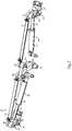
Figure 2 is a diagrammatic view of a machine system, according to one embodiment; -
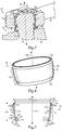
Figure 3 is a sectioned view, in perspective, of a portion of the machine system ofFigure 2 ; -
Figure 4 is an isometric view of a boot seal, according to one embodiment; -
Figure 5 is a sectioned side diagrammatic view of the boot seal ofFigure 4 ; -
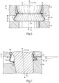
Figure 6 is a partially sectioned side diagrammatic view of a portion of the machine system ofFigure 2 ; -
Figure 7 is a sectioned side diagrammatic view similar toFigure 6 with components of the machine system tilted relative to one another; and -
Figure 8 is a graph of force versus displacement during installation of a boot seal, according to one embodiment. - Referring to
Figure 1 , there is shown amachine 10 according to the present disclosure in the context of an off-highway truck having aframe 12, adump body 16 mounted toframe 12, and each of a front and back set of groundengaging elements Machine 10 also includes amachine system 20. In the illustrated example,machine system 20 includes a steering system controllable via asteering wheel 22 or the like positioned within anoperator cab 18.System 20 could be autonomously operated in certain embodiments.System 20 includes amovable machine component 24, and anothermovable machine component 26, andcomponents components joint assembly 30 connectscomponent 24 andcomponent 26 in a finite angular pivoting range.Joint assembly 30 includes aboot seal 34 sealing betweenfirst component 24 andsecond component 26.System 20 may also include anothermovable component 28 and anotherjoint assembly 32 connectingcomponent 24 andcomponent 28, analogously pivotable in a finite angular pivoting range.Joint assembly 32 may also include aboot seal 34 sealing betweencomponent 24 andcomponent 28.Boot seals 34 may be substantially identical to one another, and as further discussed herein additional joint assemblies and additional, substantially identical boot seals may be used elsewhere inmachine system 20. - As noted above,
system 20 may include a steering system, andmachine 10 may include a ground-engaging machine such as a truck.Component 24 may include a steering arm, and each ofcomponents component 24, as further described herein. The frontground engaging element 14 visible inFigure 1 may be part of a wheel assembly 36, also including a wheel mount 38 configured to couple withframe 12 and supportingground engaging element 14 for rotation about anaxis 40. In parallel with such rotation of groundengaging element 14, an opposite and substantially mirror image wheel assembly not visible inFigure 1 will similarly rotate to enable steering ofmachine 10 in a conventional manner. As will be further apparent from the following description,boot seals 34 may be uniquely configured to seal between the respective components, and can function in a manner negating the necessity for routine lubrication of any of the associated joint assemblies inmachine system 20, providing substantial advantages over analogous systems which can require servicing to lubricate joint seals and purge debris on a daily basis, or even multiple times per day. - Referring now to
Figure 2 , there is shownsystem 20 in more detail. As noted above,component 24 may include a steering arm, which may further be an outer steering arm configured to couple with wheel assembly 36.System 20 may further include a pivotablecenter steering arm 42 having amounting shaft 44 configured to couple withframe 12 ofmachine 10. As also noted above,component 26 may include a linkage rod, which may couplecomponent 24 withframe 12.Component 28 may include a second linkage rod,coupling component 24 withcenter arm 42. In the embodiment shown,system 20 may further include a hydraulic actuator 48 configured to couple toframe 12 ofmachine 10. Actuator 48 may include ahydraulic cylinder 50, and also includes component orlinkage rod 26. Those skilled in the art will thus appreciate thatlinkage rod 26 may be reciprocable withincylinder 50 in a conventional manner forsteering machine 10.Component 28 orsecond linkage rod 28 may include a rigid linkage rod, as opposed to the extendable andretractable rod 26. -
System 20 may further include a secondouter steering arm 52, andadditional linkage rods 54 and 56 pivotably couplingouter steering arm 52 withframe 12 andcenter arm 42. A second hydraulic actuator 58 may include linkage rod 54 and ahydraulic cylinder 60. Additionaljoint assemblies 62 and 64 may couplelinkage rods 54 and 56 to steeringarm 52 in an manner substantially identical to that described in connection withsteering arm 24. Additionaljoint assemblies linkage rods center arm 42. In certain embodiments, additional joint assemblies may be used to pivotably connect actuators 48 and 58 withframe 12 inmachine 10. All of the joint assemblies described herein may be substantially identical, and may each include a substantiallyidentical boot seal 34. Accordingly, the construction of those joint assemblies and the features, function, and installation procedure respecting their boot seals may all be substantially identical at least in certain embodiments. - Referring now to
Figure 3 , there are shown additional features of ajoint assembly 30 in accordance with the present disclosure. In a practical implementation strategy,joint assembly 30 may include a ball joint assembly having aball stud 74 defining alongitudinal axis 75 and including a shaft 76 held fast withincomponent 24, and a ball 78 received within asocket eye 72 formed in arod end 70 ofcomponent 26.Joint assembly 30 may further include abearing 80 positioned withinsocket eye 72, and extending about ball 78 in a conventional manner. A cap or the like 82 is shown engaged withinsocket eye 72 inrod end 70.Cap 82 might be threaded intorod end 70 in certain embodiments. Aport 84 is shown incap 82, and could be used for delivery of grease or another lubricant into the interior ofjoint assembly 30 in a conventional manner. In many instances,joint assembly 30 will be a so-called dry joint having no lubricant, or only such lubricant as might initially be used or applied during assembly of the components.Port 84 might be blocked, or not used at all, in certain embodiments. Also shown isboot seal 34 sealing betweencomponents - Referring also now to
Figures 4 and 5 ,boot seal 34 may include aresilient seal body 100 defining acenter axis 102 and including abody wall 104 extending between a firstaxial body end 106 and a secondaxial body end 108.Body wall 104 may further extend circumferentially aroundcenter axis 102, and is shaped to deform in a unique way and for purposes which will be further apparent from the following description. Firstaxial body end 106 may define a larger diametercircular opening 110, and secondaxial body end 108 may define a smaller diametercircular opening 112. Afirst sealing ring 114 is positioned at firstaxial body end 106 and includes an exposed outerradial surface 116 positionable in radial contact withcomponent 26. An unexposed or hidden inner radial surface contacts material ofbody wall 104. Asecond sealing ring 118 is positioned at secondaxial body end 108 and has an exposed outer axial surface 120 positionable in axial contact withcomponent 24. InFigures 4 and 5 ,boot seal 34, more particularly sealbody 100, is shown as it might appear in a rest configuration wherebody wall 104 forms acurvilinear taper 122 extending between firstaxial body end 106 and secondaxial body end 108.Seal body 100 further defines anaxial body length 156, and taper 122 may extend a majority oflength 156 betweenends Body wall 104, is deformable in response to axial compression ofseal body 100 betweencomponents Figure 3 , wherebody wall 104 forms a radiallyoutward bulge 160 storing an energy of the axial compression to biassecond sealing ring 118 againstcomponent 24. Various geometric attributes ofboot seal 34 enable installation as part ofjoint assembly 30, and subsequent service insystem 20 in a manner addressing engineering challenges and field service operating concerns as further discussed herein. - In a practical implementation strategy,
body wall 104 may further include alonger wall section 124 adjacent firstaxial body end 106, and ashorter wall section 125 adjacent secondaxial body end 108.Seal body 100, more particularlybody wall 104 further includes anouter wall surface 126 having a convex axial profile withinwall section 124, and a concave axial profile withinwall section 125. The transition from convex to concave is readily apparent inFigure 5 , and enables formation of radiallyoutward bulge 160, and its subsequent function in service, in a desired manner.Body wall 104 may further include aninner wall surface 127 having a concave axial profile withinwall section 124, and a convex axial profile withinwall section 125. In addition to the profiling ofouter wall surface 126 andinner wall surface 127, a relative size of the various radiuses defined by the respective wall surfaces further supports the formation and service performance of radiallyoutward bulge 160. - In one embodiment, the convex axial profile of
outer wall surface 126 inwall section 124 defines a larger radius ofcurvature 128, and the concave axial profile ofinner wall surface 127 inwall section 124 defines a smaller radius of curvature 136, such that a radial thickness ofbody wall 104 increases from firstaxial body end 106 toward secondaxial body end 108. In a practical implementation strategy, the curvature ofsurfaces wall sections first wall section 124, and more than one radius withinwall section 125.Outer wall surface 126 may define a second radius ofcurvature 130, a third radius ofcurvature 132 and a fourth radius ofcurvature 134. Each ofradiuses radius 134 may include a concave radius of curvature.Radius 128 may be equal to about 120 millimeters (mm),radius 130 may be equal to about 13 mm, andradius 132 may be equal to about 5 mm, whereasradius 134 may be equal to about 6 mm. -
Inner wall surface 127 may analogously define a second, concave radius ofcurvature 138, a third, convex radius ofcurvature 140, and a fourth, convex radius ofcurvature 142. Radius 136 may be equal to about 117 mm,radius 138 may be equal to about 10 mm,radius 140 may be equal to about 4 mm, andradius 142 may be equal to about 10 mm. As used herein, the term "about" should be understood in the context of conventional rounding to a consistent number of significant digits. Accordingly, "about" 120 mm means from 115 mm to 124 mm, "about" 6 mm means from 5.5 mm to 6.4 mm, and so on. - The differently curved outer and inner wall surfaces 126 and 127 enable a gradual increase in radial thickness of
body wall 124 moving from firstaxial body end 106 toward secondaxial body end 108. It may be also noted thatfirst sealing ring 114 comprises about one half of the radial thickness ofbody wall 124 at firstaxial end 106.Second sealing ring 118 comprises a slightly lesser proportion of the radial thickness ofbody wall 124 at second axial end 120. A radial thickness of each of sealingrings rings Seal body 100 may be elastomeric, and softer than materials of sealingrings ring 114 may be positioned upon ashoulder 144 at firstaxial body end 106, whereassecond sealing ring 118 may be positioned upon asecond shoulder 146 at secondaxial body end 108. Each of sealingrings seal body 100. First sealingring 114 may further have an axial thickness which is greater than its radial thickness, and typically from about three to about four times greater. An axial thickness ofsecond sealing ring 118 may also be greater than its radial thickness, from about one to about two times greater. The relatively thinner axial extent of sealingring 118 may help promote the desired deformation ofseal body 110 upon installation for service. Afull width 152 or outer diameter dimension ofboot seal 34 may be about 70 mm, more particularly about 66 mm in certain embodiments, whereas aninside width 154, corresponding to a width ofopening 110 may be about 4 mm less thanwidth 152. While these dimensional attributes provide a practical implementation strategy, the present disclosure is not thusly limited, andboot seal 34 can be expected to scale up or down in size, preserving the general shape and proportional attributes disclosed herein. It may further be noted fromFigure 5 that exposed outerradial surface 116 axially transitions withouter wall surface 126.Seal body 100 may further include anaxial end surface 148. Exposed outer axial surface 120 may include a planar surface, which may radially transition withaxial end surface 148. "Transition" means that, in profile, no radial or axial offset exists between surfaces of the respective components where radially or axially abutting, as the case may be, at least as would be apparent to the naked eye.Outer wall surface 126 may further include a substantially cylindrical,non-tapered section 150 which is part oflonger wall section 124 and adjoins first sealingring 114. - Referring now to
Figure 6 , there is shownjoint assembly 30 as it might appear withboot seal 34 in its squished configuration having been axially compressed betweencomponents outward bulge 160 has formed in boot seal 36, and stores an energy of the axial compression to bias second sealing ring againstcomponent 24.Center axis 102 overlaps with alongitudinal axis 75 defined bystud 74. It may be noted that radiallyoutward bulge 160 is axially asymmetric, bulging predominantly downward in theFigure 6 illustration. Aclearance distance 86 betweencomponents bulge 160 is within the half ofclearance 86 closer tocomponent 24. In a practical implementation strategy, an axial height or body length ofboot seal 34 may be reduced by about half from its rest configuration to reach the squished configuration shown inFigure 6 . It may also be noted that a width, or outer diameter dimension, ofbulge 160 can be greater than the outer width or outer diameter dimension offirst sealing ring 114. - It will be recalled that sealing
ring 114 is positioned withinsocket eye 72. In a practical implementation strategy, sealingring 114 may be interference fitted withinsocket eye 72 such that sealingring 114 is fixed to rotate withcomponent 26 throughout a finite angular pivoting range ofcomponent 26 relative tocomponent 24.Components axes bulge 160biases sealing ring 118 againstcomponent 24. The bias may be such that sealingring 118 is fixed to rotate withcomponent 24 through only a part of the angular pivoting range, and slips relative tocomponent 24 through another part of the angular pivoting range. In a practical implementation strategy, sealingring 118 may be fixed to rotate withcomponent 24 through a minority of the angular pivoting range, and may slip relative tocomponent 24 through a majority of the angular pivoting range. In a further practical implementation strategy, the minority of the angular pivoting range may be about 10°, or plus or minus about 5° from neutral. - Referring now to
Figure 7 , there is shownjoint assembly 30pivotably connecting components components System 20 may be designed such that a certain amount of tilting betweencomponents boot seal 34 such that contact can be maintained between sealingring 118 andcomponent 24 throughout an angular tilt range, and of course between sealingring 114 andcomponent 26. It is further desirable thatboot seal 34 be designed such that contact between sealingring 118 andcomponent 24 is maintained at extremes or mechanical stop limits of both the angular pivoting range and an angular tilt range betweencomponents Figure 7 , an angle θ is shown betweencomponents Angle 0 may be about 4° or greater, such that the angular tilt range is about 8° or greater, and in certain embodiments about 12°. It may be noted that even at the limit of tilting depicted inFigure 7 , radially outward bulge is not in contact with either ofcomponents boot seal 34 may therefore be such that not only is sealingring 118 maintained in contact withcomponent 24 at stop limits of both the angular pivoting range and the angular tilt range, but also such that radiallyoutward bulge 160 does not contact either ofcomponents boot seal 34 is unlikely to contact either ofcomponents - Referring to the drawings generally, assembling a machine system such as
system 10 may include contacting outerradial surface 116 of sealingring 114 withcomponent 26 inmachine system 20, such as via interference fitting sealingring 114 withinsocket eye 72. Interferencefitting sealing ring 114 thusly can take place afterstud 74 has been positioned withinsocket eye 72 along with bearing 80, but prior to attachingstud 74 tocomponent 24.Component 24 may then be positioned aboutstud 74, and brought towardscomponent 26 to contact outer axial surface 120 withcomponent 24, and begin compressingboot seal 34 between first andsecond components boot seal 34 in this manner, it may be in its rest configuration havingcurvilinear taper 22. Ascomponent 24 is advanced towardscomponent 26 to reduceclearance 86,boot seal 34 may be compressed to its squished configuration, formingbulge 160 which stores an energy of the compression. The stored energy may bias sealingring 118 againstcomponent 24. At this stage in assembly, each of sealingrings seal body 100, fluidly seal betweencomponents second components stud 74 belowcomponent 24. This general procedure may be followed with respect to all of the joint assemblies insystem 20 as the case may be. - Referring now to
Figure 8 , there is shown agraph 200 including acurve 202 relating axial force (Newtons) to compressboot seal 34 on the Y axis to axial displacement (mm) ofcomponent 24 on the X axis. It may be noted thatseal body 100 is relatively more difficult to axially compress initially, such as for the first 2 mm or so, but becomes more easy to compress thereafter, and becomes easier still towards the full extent of desired compression, which may occur at or near 14 mm. Another way to understand what is represented bygraph 200 is that axial compression ofboot seal 34 is initially relatively difficult, and becomes increasingly difficult with further axial compression, but then becomes relatively easier to compress with further displacement, and when at about or slightly past one half of a full desired compression, the force needed to further compress boot seal 34 a given displacement actually begins to decrease. These phenomena differ from certain known boot seal designs, which much like springs tend to be harder and harder to compress as the total displacement increases, and as a result will typically differ from the present disclosure respecting the manner in which a desired axial biasing against a pivoting component could be obtained, if at all.Figure 8 further conveys the feature of most of the energy of compression being stored inboot seal 34 during compressingboot seal 34 about half way to its squished configuration, such that relatively minor adjustments or mistakes in total axial displacement when boot seal is close to its squished configuration will have relatively little impact on the biasing force applied to sealingring 118. - The present description is for illustrative purposes only, and should not be construed to narrow the breadth of the present disclosure in any way. Thus, those skilled in the art will appreciate that various modifications might be made to the presently disclosed embodiments without departing from the scope of the appended claims. Other aspects, features and advantages will be apparent upon an examination of the attached drawings and appended claims.
Claims (3)
- A boot seal (34) for a joint assembly (30, 32, 62, 64, 66, 68) connecting first and second machine components (24, 26, 28, 42, 52, 54, 56) pivotable relative to one another in a finite angular pivoting range, the boot seal (34) comprising:a resilient seal body (100) defining a center axis (102) and including a body wall (104) extending between a first axial body end (106) and a second axial body end (108) and circumferentially around the center axis (102);the first axial body end (106) defining a larger diameter circular opening (110) and the second axial body end (108) defining a smaller diameter circular opening (112);a first sealing ring (114) positioned at the first axial body end (106) and including an exposed outer radial surface (116) positionable in radial contact with the first machine component (24, 26, 28, 42, 52, 54, 56);a second sealing ring (118) positioned at the second axial body end (108) and having an exposed outer axial surface (120) positionable in axial contact with the second machine component (24, 26, 28, 42, 52, 54, 56); andthe resilient seal body (100) further defining an axial body length, and being in a rest configuration where the body wall (104) forms a curvilinear taper (122) extending a majority of the axial body length from the first to the second axial body end (106, 108), and the resilient seal body (100) being deformable in response to axial compression between the first and second machine components (24, 26, 28, 42, 52, 54, 56) to a squished configuration where the body wall (104) forms a radially outward bulge (160) storing an energy of the axial compression to bias the second sealing ring (118) against the second machine component (24, 26, 28, 42, 52, 54, 56), characterised in thatthe body wall (104) further includes a longer wall section (124) adjacent the first axial body end, (106) a shorter wall section (125) adjacent the second axial body end (108), and an outer wall surface (126) having a convex axial profile within the longer wall section (124) and a concave axial profile within the shorter wall section (125); and in thatthe body wall (104) further includes an inner wall surface (127) having a concave axial profile within the longer wall section (124), and a convex axial profile within the shorter wall section (125).
- The boot seal (34) of claim 1 wherein the convex axial profile of the outer wall surface (126) defines a larger radius of curvature, and the concave axial profile of the inner wall surface (127) defines a smaller radius of curvature, such that a radial thickness of the body wall (104) increases from the first axial body end (106) toward the second axial body end (108);
wherein the resilient seal body (100) is elastomeric and each of the first and second sealing rings (114, 118) is metallic;
wherein each of the first and second sealing rings (114, 118) is cylindrical, and positioned upon a shoulder (144, 146) formed in the resilient seal body (100) at the corresponding first and second axial ends (106, 108). - The boot seal (34) of claim 2 wherein the outer wall surface (126) transitions with the exposed outer radial surface (116), and wherein the resilient seal body (100) further includes an axial end surface (148) transitioning with the exposed outer axial surface (120).
Applications Claiming Priority (2)
| Application Number | Priority Date | Filing Date | Title |
|---|---|---|---|
| US13/848,219 US9109702B2 (en) | 2013-03-21 | 2013-03-21 | Boot seal for machine system and method |
| PCT/US2014/031074 WO2014153354A1 (en) | 2013-03-21 | 2014-03-18 | Boot seal for machine system and method |
Publications (2)
| Publication Number | Publication Date |
|---|---|
| EP2976537A1 EP2976537A1 (en) | 2016-01-27 |
| EP2976537B1 true EP2976537B1 (en) | 2019-10-09 |
Family
ID=50489447
Family Applications (1)
| Application Number | Title | Priority Date | Filing Date |
|---|---|---|---|
| EP14717967.5A Active EP2976537B1 (en) | 2013-03-21 | 2014-03-18 | Boot seal for machine system and method |
Country Status (6)
| Country | Link |
|---|---|
| US (1) | US9109702B2 (en) |
| EP (1) | EP2976537B1 (en) |
| CN (1) | CN105102834A (en) |
| AU (1) | AU2014236014B2 (en) |
| ES (1) | ES2764160T3 (en) |
| WO (1) | WO2014153354A1 (en) |
Families Citing this family (7)
| Publication number | Priority date | Publication date | Assignee | Title |
|---|---|---|---|---|
| CN109578701B (en) * | 2017-09-28 | 2021-10-26 | 中国科学院长春光学精密机械与物理研究所 | Air sealing device and theodolite |
| US10995860B2 (en) * | 2018-05-31 | 2021-05-04 | Aktiebolaget Skf | Axial face seal assembly with outwardly-biased backing rings |
| USD936190S1 (en) | 2020-02-27 | 2021-11-16 | Caterpillar Inc. | Ripple seal |
| US11261973B2 (en) * | 2020-02-27 | 2022-03-01 | Caterpillar Inc. | Seal having undulating seal component and systems, assemblies, and methods thereof |
| CN111642219B (en) * | 2020-06-04 | 2021-08-24 | 温州科技职业学院 | A yam harvester |
| CN112067206B (en) * | 2020-08-20 | 2022-11-22 | 江门龙浩智能装备有限公司 | Sealing method |
| USD1117674S1 (en) | 2023-08-09 | 2026-03-10 | Caterpillar Inc. | Frame seal |
Family Cites Families (17)
| Publication number | Priority date | Publication date | Assignee | Title |
|---|---|---|---|---|
| US3175834A (en) | 1961-06-01 | 1965-03-30 | Chrysler Corp | Ball joint seal |
| US3322445A (en) | 1964-10-13 | 1967-05-30 | Chrysler Corp | Ball joint seal |
| GB1150954A (en) | 1966-09-16 | 1969-05-07 | Birfield Eng Ltd | Improvements in or relating to Flexible Seals |
| AU418260B2 (en) * | 1967-02-09 | 1971-10-27 | Trw Inc | Joint assembly |
| DE1600429B1 (en) * | 1967-03-09 | 1970-06-18 | Daimler Benz Ag | Sealing sleeve made of elastic material, especially for rotating drive joints |
| JPS523068B2 (en) | 1973-09-25 | 1977-01-26 | ||
| FR2655104B1 (en) | 1989-11-30 | 1995-01-27 | Glaenzer Spicer Sa | TRANSMISSION JOINT. |
| US6644883B2 (en) * | 1999-09-15 | 2003-11-11 | Dana Corporation | Secondary sealing element for a boot seal |
| US6357956B1 (en) * | 1999-12-10 | 2002-03-19 | Dana Corporation | Unitized boot seal for ball joints |
| US20050250586A1 (en) | 2002-08-27 | 2005-11-10 | Nsk Ltd. | Dust cover for steering shaft |
| DE10350640B4 (en) * | 2003-10-29 | 2005-11-17 | Zf Friedrichshafen Ag | Ball joint for a motor vehicle |
| JP2007056995A (en) | 2005-08-24 | 2007-03-08 | Ntn Corp | Flexible boot for constant velocity universal joint |
| CN101297139B (en) | 2005-08-25 | 2013-03-20 | 费德罗-莫格尔公司 | Dust boot with grease channel |
| DE102006039861A1 (en) | 2006-08-25 | 2008-03-13 | Zf Friedrichshafen Ag | Sealing or bellows |
| US8414215B2 (en) * | 2008-11-07 | 2013-04-09 | Trw Automotive U.S. Llc | Sealing structure for use with a ball and socket joint |
| CN202040199U (en) * | 2011-05-13 | 2011-11-16 | 山东安博机械科技股份有限公司 | Spherical pin with dustproof sealing ring |
| CN202732669U (en) * | 2012-08-30 | 2013-02-13 | 宁波优适捷传动件有限公司 | Flexible ball joint assembly bushing for controlling heavy truck |
-
2013
- 2013-03-21 US US13/848,219 patent/US9109702B2/en active Active
-
2014
- 2014-03-18 WO PCT/US2014/031074 patent/WO2014153354A1/en not_active Ceased
- 2014-03-18 EP EP14717967.5A patent/EP2976537B1/en active Active
- 2014-03-18 CN CN201480016405.2A patent/CN105102834A/en active Pending
- 2014-03-18 ES ES14717967T patent/ES2764160T3/en active Active
- 2014-03-18 AU AU2014236014A patent/AU2014236014B2/en not_active Ceased
Non-Patent Citations (1)
| Title |
|---|
| None * |
Also Published As
| Publication number | Publication date |
|---|---|
| US20140286693A1 (en) | 2014-09-25 |
| WO2014153354A1 (en) | 2014-09-25 |
| ES2764160T3 (en) | 2020-06-02 |
| AU2014236014B2 (en) | 2016-06-23 |
| EP2976537A1 (en) | 2016-01-27 |
| CN105102834A (en) | 2015-11-25 |
| AU2014236014A1 (en) | 2015-11-05 |
| US9109702B2 (en) | 2015-08-18 |
Similar Documents
| Publication | Publication Date | Title |
|---|---|---|
| AU2014236014B2 (en) | Boot seal for machine system and method | |
| CN203463483U (en) | Sealing ball joint | |
| EP3404275B1 (en) | Slide bearing | |
| EP2577081B1 (en) | Flexible joint | |
| US10107314B2 (en) | Cylinder having a floating piston, low profile swivel cap, and lubricated rod | |
| US8801318B2 (en) | Joint | |
| RU2708930C2 (en) | Joint assembly seal | |
| US20170102028A1 (en) | Ball joint assembly and method of making | |
| AU2011258294A1 (en) | Seal assembly and method for forming a seal assembly | |
| US9856892B2 (en) | Cylinder having a floating piston, swivel cap, and lubricated rod | |
| AU2016359686B2 (en) | Circumferential debris seal for pinned joints | |
| CN103388617A (en) | Sleeve joint for vehicle | |
| CN107972431B (en) | High angle ball joint assembly | |
| CA2923488C (en) | Cylinder having a floating piston, low profile swivel cap, and lubricated rod | |
| US20090060633A1 (en) | Joint arrangement and/or bearing arrangement | |
| GB2417054A (en) | A bush including a resilient member that is less susceptible to shearing | |
| JP5807397B2 (en) | Sealing device | |
| JP2013155806A (en) | Cross shaft type universal joint | |
| JP5195987B2 (en) | Sealing system | |
| WO2016014670A1 (en) | Cylinder having a floating piston, swivel cap, and lubricated rod | |
| JPH0552306U (en) | Sliding structure of rotary actuator | |
| JP2008281097A (en) | Boot and power transmission shaft |
Legal Events
| Date | Code | Title | Description |
|---|---|---|---|
| PUAI | Public reference made under article 153(3) epc to a published international application that has entered the european phase |
Free format text: ORIGINAL CODE: 0009012 |
|
| 17P | Request for examination filed |
Effective date: 20150902 |
|
| AK | Designated contracting states |
Kind code of ref document: A1 Designated state(s): AL AT BE BG CH CY CZ DE DK EE ES FI FR GB GR HR HU IE IS IT LI LT LU LV MC MK MT NL NO PL PT RO RS SE SI SK SM TR |
|
| AX | Request for extension of the european patent |
Extension state: BA ME |
|
| DAX | Request for extension of the european patent (deleted) | ||
| GRAP | Despatch of communication of intention to grant a patent |
Free format text: ORIGINAL CODE: EPIDOSNIGR1 |
|
| STAA | Information on the status of an ep patent application or granted ep patent |
Free format text: STATUS: GRANT OF PATENT IS INTENDED |
|
| INTG | Intention to grant announced |
Effective date: 20190418 |
|
| GRAS | Grant fee paid |
Free format text: ORIGINAL CODE: EPIDOSNIGR3 |
|
| GRAA | (expected) grant |
Free format text: ORIGINAL CODE: 0009210 |
|
| STAA | Information on the status of an ep patent application or granted ep patent |
Free format text: STATUS: THE PATENT HAS BEEN GRANTED |
|
| AK | Designated contracting states |
Kind code of ref document: B1 Designated state(s): AL AT BE BG CH CY CZ DE DK EE ES FI FR GB GR HR HU IE IS IT LI LT LU LV MC MK MT NL NO PL PT RO RS SE SI SK SM TR |
|
| RAP1 | Party data changed (applicant data changed or rights of an application transferred) |
Owner name: CATERPILLAR INC. |
|
| REG | Reference to a national code |
Ref country code: GB Ref legal event code: FG4D |
|
| REG | Reference to a national code |
Ref country code: CH Ref legal event code: EP |
|
| REG | Reference to a national code |
Ref country code: IE Ref legal event code: FG4D |
|
| REG | Reference to a national code |
Ref country code: DE Ref legal event code: R096 Ref document number: 602014054859 Country of ref document: DE |
|
| REG | Reference to a national code |
Ref country code: AT Ref legal event code: REF Ref document number: 1189171 Country of ref document: AT Kind code of ref document: T Effective date: 20191115 |
|
| REG | Reference to a national code |
Ref country code: NL Ref legal event code: MP Effective date: 20191009 |
|
| REG | Reference to a national code |
Ref country code: LT Ref legal event code: MG4D |
|
| REG | Reference to a national code |
Ref country code: AT Ref legal event code: MK05 Ref document number: 1189171 Country of ref document: AT Kind code of ref document: T Effective date: 20191009 |
|
| PG25 | Lapsed in a contracting state [announced via postgrant information from national office to epo] |
Ref country code: NO Free format text: LAPSE BECAUSE OF FAILURE TO SUBMIT A TRANSLATION OF THE DESCRIPTION OR TO PAY THE FEE WITHIN THE PRESCRIBED TIME-LIMIT Effective date: 20200109 Ref country code: PL Free format text: LAPSE BECAUSE OF FAILURE TO SUBMIT A TRANSLATION OF THE DESCRIPTION OR TO PAY THE FEE WITHIN THE PRESCRIBED TIME-LIMIT Effective date: 20191009 Ref country code: BG Free format text: LAPSE BECAUSE OF FAILURE TO SUBMIT A TRANSLATION OF THE DESCRIPTION OR TO PAY THE FEE WITHIN THE PRESCRIBED TIME-LIMIT Effective date: 20200109 Ref country code: FI Free format text: LAPSE BECAUSE OF FAILURE TO SUBMIT A TRANSLATION OF THE DESCRIPTION OR TO PAY THE FEE WITHIN THE PRESCRIBED TIME-LIMIT Effective date: 20191009 Ref country code: LT Free format text: LAPSE BECAUSE OF FAILURE TO SUBMIT A TRANSLATION OF THE DESCRIPTION OR TO PAY THE FEE WITHIN THE PRESCRIBED TIME-LIMIT Effective date: 20191009 Ref country code: LV Free format text: LAPSE BECAUSE OF FAILURE TO SUBMIT A TRANSLATION OF THE DESCRIPTION OR TO PAY THE FEE WITHIN THE PRESCRIBED TIME-LIMIT Effective date: 20191009 Ref country code: SE Free format text: LAPSE BECAUSE OF FAILURE TO SUBMIT A TRANSLATION OF THE DESCRIPTION OR TO PAY THE FEE WITHIN THE PRESCRIBED TIME-LIMIT Effective date: 20191009 Ref country code: PT Free format text: LAPSE BECAUSE OF FAILURE TO SUBMIT A TRANSLATION OF THE DESCRIPTION OR TO PAY THE FEE WITHIN THE PRESCRIBED TIME-LIMIT Effective date: 20200210 Ref country code: GR Free format text: LAPSE BECAUSE OF FAILURE TO SUBMIT A TRANSLATION OF THE DESCRIPTION OR TO PAY THE FEE WITHIN THE PRESCRIBED TIME-LIMIT Effective date: 20200110 Ref country code: AT Free format text: LAPSE BECAUSE OF FAILURE TO SUBMIT A TRANSLATION OF THE DESCRIPTION OR TO PAY THE FEE WITHIN THE PRESCRIBED TIME-LIMIT Effective date: 20191009 Ref country code: NL Free format text: LAPSE BECAUSE OF FAILURE TO SUBMIT A TRANSLATION OF THE DESCRIPTION OR TO PAY THE FEE WITHIN THE PRESCRIBED TIME-LIMIT Effective date: 20191009 |
|
| PG25 | Lapsed in a contracting state [announced via postgrant information from national office to epo] |
Ref country code: IS Free format text: LAPSE BECAUSE OF FAILURE TO SUBMIT A TRANSLATION OF THE DESCRIPTION OR TO PAY THE FEE WITHIN THE PRESCRIBED TIME-LIMIT Effective date: 20200224 Ref country code: HR Free format text: LAPSE BECAUSE OF FAILURE TO SUBMIT A TRANSLATION OF THE DESCRIPTION OR TO PAY THE FEE WITHIN THE PRESCRIBED TIME-LIMIT Effective date: 20191009 Ref country code: RS Free format text: LAPSE BECAUSE OF FAILURE TO SUBMIT A TRANSLATION OF THE DESCRIPTION OR TO PAY THE FEE WITHIN THE PRESCRIBED TIME-LIMIT Effective date: 20191009 |
|
| REG | Reference to a national code |
Ref country code: ES Ref legal event code: FG2A Ref document number: 2764160 Country of ref document: ES Kind code of ref document: T3 Effective date: 20200602 |
|
| PG25 | Lapsed in a contracting state [announced via postgrant information from national office to epo] |
Ref country code: AL Free format text: LAPSE BECAUSE OF FAILURE TO SUBMIT A TRANSLATION OF THE DESCRIPTION OR TO PAY THE FEE WITHIN THE PRESCRIBED TIME-LIMIT Effective date: 20191009 |
|
| REG | Reference to a national code |
Ref country code: DE Ref legal event code: R097 Ref document number: 602014054859 Country of ref document: DE |
|
| PG2D | Information on lapse in contracting state deleted |
Ref country code: IS |
|
| PG25 | Lapsed in a contracting state [announced via postgrant information from national office to epo] |
Ref country code: CZ Free format text: LAPSE BECAUSE OF FAILURE TO SUBMIT A TRANSLATION OF THE DESCRIPTION OR TO PAY THE FEE WITHIN THE PRESCRIBED TIME-LIMIT Effective date: 20191009 Ref country code: DK Free format text: LAPSE BECAUSE OF FAILURE TO SUBMIT A TRANSLATION OF THE DESCRIPTION OR TO PAY THE FEE WITHIN THE PRESCRIBED TIME-LIMIT Effective date: 20191009 Ref country code: EE Free format text: LAPSE BECAUSE OF FAILURE TO SUBMIT A TRANSLATION OF THE DESCRIPTION OR TO PAY THE FEE WITHIN THE PRESCRIBED TIME-LIMIT Effective date: 20191009 Ref country code: RO Free format text: LAPSE BECAUSE OF FAILURE TO SUBMIT A TRANSLATION OF THE DESCRIPTION OR TO PAY THE FEE WITHIN THE PRESCRIBED TIME-LIMIT Effective date: 20191009 Ref country code: IS Free format text: LAPSE BECAUSE OF FAILURE TO SUBMIT A TRANSLATION OF THE DESCRIPTION OR TO PAY THE FEE WITHIN THE PRESCRIBED TIME-LIMIT Effective date: 20200209 |
|
| PLBE | No opposition filed within time limit |
Free format text: ORIGINAL CODE: 0009261 |
|
| STAA | Information on the status of an ep patent application or granted ep patent |
Free format text: STATUS: NO OPPOSITION FILED WITHIN TIME LIMIT |
|
| PG25 | Lapsed in a contracting state [announced via postgrant information from national office to epo] |
Ref country code: SM Free format text: LAPSE BECAUSE OF FAILURE TO SUBMIT A TRANSLATION OF THE DESCRIPTION OR TO PAY THE FEE WITHIN THE PRESCRIBED TIME-LIMIT Effective date: 20191009 Ref country code: SK Free format text: LAPSE BECAUSE OF FAILURE TO SUBMIT A TRANSLATION OF THE DESCRIPTION OR TO PAY THE FEE WITHIN THE PRESCRIBED TIME-LIMIT Effective date: 20191009 |
|
| 26N | No opposition filed |
Effective date: 20200710 |
|
| PG25 | Lapsed in a contracting state [announced via postgrant information from national office to epo] |
Ref country code: MC Free format text: LAPSE BECAUSE OF FAILURE TO SUBMIT A TRANSLATION OF THE DESCRIPTION OR TO PAY THE FEE WITHIN THE PRESCRIBED TIME-LIMIT Effective date: 20191009 |
|
| REG | Reference to a national code |
Ref country code: CH Ref legal event code: PL |
|
| PG25 | Lapsed in a contracting state [announced via postgrant information from national office to epo] |
Ref country code: SI Free format text: LAPSE BECAUSE OF FAILURE TO SUBMIT A TRANSLATION OF THE DESCRIPTION OR TO PAY THE FEE WITHIN THE PRESCRIBED TIME-LIMIT Effective date: 20191009 |
|
| REG | Reference to a national code |
Ref country code: BE Ref legal event code: MM Effective date: 20200331 |
|
| PG25 | Lapsed in a contracting state [announced via postgrant information from national office to epo] |
Ref country code: LU Free format text: LAPSE BECAUSE OF NON-PAYMENT OF DUE FEES Effective date: 20200318 |
|
| PG25 | Lapsed in a contracting state [announced via postgrant information from national office to epo] |
Ref country code: LI Free format text: LAPSE BECAUSE OF NON-PAYMENT OF DUE FEES Effective date: 20200331 Ref country code: IE Free format text: LAPSE BECAUSE OF NON-PAYMENT OF DUE FEES Effective date: 20200318 Ref country code: CH Free format text: LAPSE BECAUSE OF NON-PAYMENT OF DUE FEES Effective date: 20200331 |
|
| PG25 | Lapsed in a contracting state [announced via postgrant information from national office to epo] |
Ref country code: BE Free format text: LAPSE BECAUSE OF NON-PAYMENT OF DUE FEES Effective date: 20200331 |
|
| PGFP | Annual fee paid to national office [announced via postgrant information from national office to epo] |
Ref country code: GB Payment date: 20220225 Year of fee payment: 9 Ref country code: DE Payment date: 20220217 Year of fee payment: 9 |
|
| PG25 | Lapsed in a contracting state [announced via postgrant information from national office to epo] |
Ref country code: MT Free format text: LAPSE BECAUSE OF FAILURE TO SUBMIT A TRANSLATION OF THE DESCRIPTION OR TO PAY THE FEE WITHIN THE PRESCRIBED TIME-LIMIT Effective date: 20191009 Ref country code: CY Free format text: LAPSE BECAUSE OF FAILURE TO SUBMIT A TRANSLATION OF THE DESCRIPTION OR TO PAY THE FEE WITHIN THE PRESCRIBED TIME-LIMIT Effective date: 20191009 |
|
| PGFP | Annual fee paid to national office [announced via postgrant information from national office to epo] |
Ref country code: TR Payment date: 20220224 Year of fee payment: 9 Ref country code: IT Payment date: 20220217 Year of fee payment: 9 Ref country code: FR Payment date: 20220218 Year of fee payment: 9 |
|
| PG25 | Lapsed in a contracting state [announced via postgrant information from national office to epo] |
Ref country code: MK Free format text: LAPSE BECAUSE OF FAILURE TO SUBMIT A TRANSLATION OF THE DESCRIPTION OR TO PAY THE FEE WITHIN THE PRESCRIBED TIME-LIMIT Effective date: 20191009 |
|
| PGFP | Annual fee paid to national office [announced via postgrant information from national office to epo] |
Ref country code: ES Payment date: 20220401 Year of fee payment: 9 |
|
| P01 | Opt-out of the competence of the unified patent court (upc) registered |
Effective date: 20230517 |
|
| REG | Reference to a national code |
Ref country code: DE Ref legal event code: R119 Ref document number: 602014054859 Country of ref document: DE |
|
| GBPC | Gb: european patent ceased through non-payment of renewal fee |
Effective date: 20230318 |
|
| PG25 | Lapsed in a contracting state [announced via postgrant information from national office to epo] |
Ref country code: GB Free format text: LAPSE BECAUSE OF NON-PAYMENT OF DUE FEES Effective date: 20230318 |
|
| PG25 | Lapsed in a contracting state [announced via postgrant information from national office to epo] |
Ref country code: GB Free format text: LAPSE BECAUSE OF NON-PAYMENT OF DUE FEES Effective date: 20230318 Ref country code: FR Free format text: LAPSE BECAUSE OF NON-PAYMENT OF DUE FEES Effective date: 20230331 Ref country code: DE Free format text: LAPSE BECAUSE OF NON-PAYMENT OF DUE FEES Effective date: 20231003 |
|
| PG25 | Lapsed in a contracting state [announced via postgrant information from national office to epo] |
Ref country code: IT Free format text: LAPSE BECAUSE OF NON-PAYMENT OF DUE FEES Effective date: 20230318 |
|
| REG | Reference to a national code |
Ref country code: ES Ref legal event code: FD2A Effective date: 20240527 |
|
| PG25 | Lapsed in a contracting state [announced via postgrant information from national office to epo] |
Ref country code: ES Free format text: LAPSE BECAUSE OF NON-PAYMENT OF DUE FEES Effective date: 20230319 |
|
| PG25 | Lapsed in a contracting state [announced via postgrant information from national office to epo] |
Ref country code: ES Free format text: LAPSE BECAUSE OF NON-PAYMENT OF DUE FEES Effective date: 20230319 |