EP2976513B1 - Ölgeschmierte arbeitsmaschine - Google Patents
Ölgeschmierte arbeitsmaschine Download PDFInfo
- Publication number
- EP2976513B1 EP2976513B1 EP14710909.4A EP14710909A EP2976513B1 EP 2976513 B1 EP2976513 B1 EP 2976513B1 EP 14710909 A EP14710909 A EP 14710909A EP 2976513 B1 EP2976513 B1 EP 2976513B1
- Authority
- EP
- European Patent Office
- Prior art keywords
- oil
- working machine
- venting duct
- flow direction
- section
- Prior art date
- Legal status (The legal status is an assumption and is not a legal conclusion. Google has not performed a legal analysis and makes no representation as to the accuracy of the status listed.)
- Active
Links
- 238000013022 venting Methods 0.000 claims description 33
- 239000002245 particle Substances 0.000 claims description 13
- 238000002485 combustion reaction Methods 0.000 claims description 9
- 238000007599 discharging Methods 0.000 claims description 2
- 230000000630 rising effect Effects 0.000 claims description 2
- 239000007789 gas Substances 0.000 description 36
- 238000000926 separation method Methods 0.000 description 13
- 238000009423 ventilation Methods 0.000 description 8
- 239000010408 film Substances 0.000 description 7
- 239000000126 substance Substances 0.000 description 5
- 210000003027 ear inner Anatomy 0.000 description 4
- 230000004888 barrier function Effects 0.000 description 2
- 230000008021 deposition Effects 0.000 description 2
- 230000005484 gravity Effects 0.000 description 2
- 239000000463 material Substances 0.000 description 2
- 230000000717 retained effect Effects 0.000 description 2
- 239000010409 thin film Substances 0.000 description 2
- 238000011144 upstream manufacturing Methods 0.000 description 2
- 230000035508 accumulation Effects 0.000 description 1
- 238000009825 accumulation Methods 0.000 description 1
- 230000015572 biosynthetic process Effects 0.000 description 1
- 230000000740 bleeding effect Effects 0.000 description 1
- 238000004140 cleaning Methods 0.000 description 1
- 230000001427 coherent effect Effects 0.000 description 1
- 150000001875 compounds Chemical class 0.000 description 1
- 238000010276 construction Methods 0.000 description 1
- 239000000446 fuel Substances 0.000 description 1
- 238000009434 installation Methods 0.000 description 1
- 238000005461 lubrication Methods 0.000 description 1
- 239000002184 metal Substances 0.000 description 1
- 239000003595 mist Substances 0.000 description 1
- 238000001556 precipitation Methods 0.000 description 1
- 238000002360 preparation method Methods 0.000 description 1
Images


Classifications
-
- F—MECHANICAL ENGINEERING; LIGHTING; HEATING; WEAPONS; BLASTING
- F01—MACHINES OR ENGINES IN GENERAL; ENGINE PLANTS IN GENERAL; STEAM ENGINES
- F01M—LUBRICATING OF MACHINES OR ENGINES IN GENERAL; LUBRICATING INTERNAL COMBUSTION ENGINES; CRANKCASE VENTILATING
- F01M13/00—Crankcase ventilating or breathing
- F01M13/04—Crankcase ventilating or breathing having means for purifying air before leaving crankcase, e.g. removing oil
-
- F—MECHANICAL ENGINEERING; LIGHTING; HEATING; WEAPONS; BLASTING
- F01—MACHINES OR ENGINES IN GENERAL; ENGINE PLANTS IN GENERAL; STEAM ENGINES
- F01M—LUBRICATING OF MACHINES OR ENGINES IN GENERAL; LUBRICATING INTERNAL COMBUSTION ENGINES; CRANKCASE VENTILATING
- F01M13/00—Crankcase ventilating or breathing
- F01M13/04—Crankcase ventilating or breathing having means for purifying air before leaving crankcase, e.g. removing oil
- F01M2013/0433—Crankcase ventilating or breathing having means for purifying air before leaving crankcase, e.g. removing oil with a deflection device, e.g. screen
-
- F—MECHANICAL ENGINEERING; LIGHTING; HEATING; WEAPONS; BLASTING
- F01—MACHINES OR ENGINES IN GENERAL; ENGINE PLANTS IN GENERAL; STEAM ENGINES
- F01M—LUBRICATING OF MACHINES OR ENGINES IN GENERAL; LUBRICATING INTERNAL COMBUSTION ENGINES; CRANKCASE VENTILATING
- F01M13/00—Crankcase ventilating or breathing
- F01M13/04—Crankcase ventilating or breathing having means for purifying air before leaving crankcase, e.g. removing oil
- F01M2013/0461—Crankcase ventilating or breathing having means for purifying air before leaving crankcase, e.g. removing oil with a labyrinth
Definitions
- the invention relates to an oil-lubricated working machine, in particular an internal combustion engine, comprising a cavity filled with particle-containing, in particular oily gas and a venting channel connected to the cavity for discharging gas from the cavity, wherein the venting channel has a free flow cross section extending in a flow direction of the venting channel and is disposed opposite to a horizontal plane at an angle between 45 ° and 90 °.
- lubrication with a thin film of oil is provided on moving parts such as pistons, valves, shafts or the like.
- a gas-filled cavity remains to be vented.
- air is drawn in, compressed and then burned with a fuel to drive a piston guided in a cylinder.
- leakage gases which are also referred to as blow-by gas, are generated in the region of the cylinder and are removed in order to avoid overpressure.
- the blowby gas is supplied to an air intake duct of the internal combustion engine.
- the blow-by gas is usually passed through an oil separator which deposits and recovers at least a portion of the oil contained in the blow-by gas in the form of a mist or droplet.
- the separated oil is returned directly into the gas-filled cavity, so for example, the cylinder head or the crankcase, or in a drip pan of the oil circuit.
- Oil separation devices are known from the prior art, which have a labyrinth, a baffle plate, a separator ring or a swirl generator. A particularly compact construction of the oil separation device is possible in particular when it is inserted into a camshaft.
- Oil separation devices with a baffle separator are for example out WO 01/92690 A1 .
- a labyrinth as a separator is from the US 4,667,647 known.
- an oil separator can also be integrated into a camshaft.
- Corresponding embodiments are made WO 2006/119737 A1 . JP 8-284634 and US 4,651,704 known.
- the US 4,329,968 describes a centrifugal oil separator disposed within a crankcase.
- the oil separation chamber is arranged above a camshaft and runs correspondingly horizontally. Accordingly, the deposition of oil from the blow-by gas forms a substantially uniform film, which can drip down at the ribs.
- a venting channel is provided with ribs. The oily gas is purified according to the cited prior art to the extent required by the ⁇ labscheide issued and then discharged through a simple vent channel.
- the object of the present invention is to achieve an improved separation of particles and condensate, in particular oil, with particularly simple means.
- the object is achieved in that the venting channel outside of the free flow cross-section on an inner wall has a plurality of successive in the flow direction ribs or grooves.
- the present invention is based on the finding that the separation performance of particles and condensate can be significantly improved by the configuration of the usually separate oil separation device, even if the ventilation channel has a free flow cross section extending in the flow direction and so that is free of fittings in the form of labyrinths, baffles, screens or the like.
- the present invention is further based on the finding that, at least over a certain period of operation, a film can form on the inner wall of the ventilation channel, by the precipitation of condensate and / or the attachment of particles such as oil droplets.
- a film particularly an oil film, may be entrained by the flowing gas and combusted, for example, when the blow-by gas is supplied to an air intake passage in an internal combustion engine.
- a separation of the particles precipitated on the inner wall and of the separated condensate is carried out by the flow of the gas.
- the structuring of the inner wall by ribs or grooves obstructs a uniform flow of the gas directly on the inner wall, without the entire flow resistance increasing significantly.
- the largest part of the interior of the ventilation channel is formed by the free flow cross-section.
- the ribs or grooves provide a barrier to a film of particles and / or condensate entrained by the flowing gas, so that these substances are retained.
- the grooves or on the ribs from the flow of the gas shaded areas in which the particles and / or the condensate, in particular oil, can collect.
- At least the accumulated on the inner wall of the venting channel condensate or the accumulated particles can be retained, whereby overall the separation efficiency is improved, even if the vent channel according to a preferred embodiment of the invention is preceded by a per se known oil separator.
- the vent channel according to a preferred embodiment of the invention is preceded by a per se known oil separator.
- unchanged default values in terms of oil separation or particle and condensate separation can be reduced in the context of such an embodiment of the design effort of the upstream oil separator.
- the venting channel has a free flow cross-section and is therefore not provided with baffle plates or the like.
- an upstream ⁇ labscheide dressed can be arranged in a feed channel, which merges directly into the vent passage.
- a feed channel and the venting channel according to the invention can merge integrally with one another, in which case the feed channel and the venting channel form sections of a compact, coherent element.
- the division into the feed channel and vent channel then results from the function and design, wherein the feed channel receives a suitable cutting device and wherein the adjoining vent channel as described has a free flow cross-section.
- the vent channel is arranged opposite a horizontal plane at an angle between 45 ° and 90 °.
- the condensate and particles deposited on the ribs or grooves can then be removed in the form of droplets, such as oil, by gravity against the flow direction of the gas.
- backflow may occur both during operation of the working machine against the flow of the gas or at least in the absence of flow of the gas during a pause in operation.
- the specified angle relative to the horizontal refers to the built-in working machine or to the intended installation position of the working machine or the venting channel.
- the vent channel can run without restriction within a housing of the machine or attached to the housing or connected to the housing.
- the successive ribs or grooves in the flow direction are formed by a helically extending on the inner wall in the flow direction projection or a spirally extending recess, in which case the successive ribs or grooves in the flow direction sections of such Spiral are.
- the deposited substances such as oil can collect along the spiral and flow along the spiral.
- the longitudinally successive ribs or grooves are not connected to each other.
- the ribs or grooves run in the flow direction or counter to the flow direction V-shaped.
- the ribs or grooves have in or opposite to the flow direction pointing tips with two adjoining, laterally sloping or rising legs.
- other shapes such as a waveform or unconnected legs are possible.
- the ribs are V-shaped or in the form of unconnected, straight legs, the angle of the legs opposite a cross-sectional plane, for example, between 10 ° and 45 °.
- the deposited substances such as oil can then flow along the webs or grooves and collect at the ends of the legs, for example in corners of the flow cross-section.
- Such a configuration is particularly useful when the vent channel according to a particularly preferred embodiment of the invention has a rectangular or a substantially rectangular cross-section.
- the ribs or grooves are intended to retain substances deposited directly on the inner wall of the ventilation channel, but do not substantially increase the flow resistance for the gas.
- the free flow cross section occupies at least 80%, particularly preferably at least 90%, of a maximum internal cross section of the ventilation channel.
- the maximum internal cross-section is determined in an embodiment with ribs, starting from the inner wall from which the ribs protrude. In a configuration with grooves, the maximum inner cross section is determined starting from the foot of the grooves.
- the vent channel can have inner wall sections lying opposite one another, wherein the ribs or the grooves on the opposite inner wall sections are arranged alternately with an offset with respect to one another as seen in the flow direction.
- the venting channel can be formed from a front part and a rear part which run in the direction of flow, the front part forming an inner wall section in the form of a front wall and the rear part forming an inner wall section in the form of a rear wall.
- the preparation of the vent channel of at least two parts allows easy formation of the ribs or grooves.
- the two parts can be connected without restriction force / form and / or cohesive with each other, which can be provided with a seal just in a compound by force and form fit the joint.
- the vent channel can be made in particular of metal or plastic, wherein plastic is preferred in terms of processability and material costs.
- the ventilation channel is formed from at least two parts, then these can be glued or welded together in a particularly simple manner, in order to allow a secure and permanent connection.
- the present invention relates to an oil-lubricated working machine, in particular an internal combustion engine comprising a cavity filled with oily gas, which may in particular be a cylinder head or a camshaft housing or a crankcase.
- oily gas which may in particular be a cylinder head or a camshaft housing or a crankcase.
- other substances in the form of particles or of condensate can be contained in the gas, which are separated just like the oil.
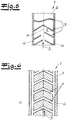
- a vent channel 1 for the discharge of gas from the cavity is connected, wherein the vent channel 1 has a in a flow direction S of the vent passage 1 extending free flow cross section 2.
- venting channel 1 outside of the free flow cross-section 2 on an inner wall has a plurality of successive ribs 3 in the flow direction.
- the vent channel 1 may be formed of a front part and a rear part, which extend in the flow direction S, wherein the front part of an inner wall portion in the form of a front wall 4 and the rear part of an inner wall portion in the form of a Form the back wall 5.
- the front wall 4 and the rear wall 5 are each provided with ribs 3, which are seen in the flow direction S arranged alternately with an offset to each other.
- ribs 3 have a contour.
- the individual ribs 3 in the flow direction S are V-shaped and have a pointing in the flow direction S tip with two adjoining laterally sloping legs.
- venting channel 1 is preferably arranged perpendicular or at least approximately perpendicular.
- the collected oil can drain to the sides and collect there.
- the Fig. 3 shows a cross section, according to which the venting channel 1 has a rectangular shape.
- the side walls 6 between the front wall 4 and the rear wall 5 can be provided with ribs 3 ', which are not shown in the other figures for reasons of clarity.
- the ribs 3 'of the side walls 6 may also be V-shaped or else run obliquely between the mutually offset ribs on the front wall 4 and the rear wall 5.
- the lateral limbs of the ribs 3 may, for example, have an angle ⁇ between 10 ° and 45 ° with respect to a cross-sectional plane ( Fig. 4 ) to allow the described outflow of oil.
- ribs 3 In the Fig. 5 is indicated that basically different shapes of ribs 3 come into consideration. In addition to a V-shape, for example, a waveform is possible. In addition, the ribs 3 may also be formed of not connected, obliquely extending legs.
- ribs and grooves 7 may be provided on the inner wall of the vent passage 1 to retain oil and can be derived. It is crucial in the context of the invention that the inner wall of the venting channel 1 has a structuring with collecting spaces for the oil.
- a rib structure is present when the inwardly projecting surfaces amount to less than 50% of the total area. With a larger proportion of the protruding areas, the recesses resulting therefrom are referred to as grooves 7.
- a free flow cross-section 2 which occupies at least 80%, preferably at least 90%, of a maximum internal cross-section of the ventilation channel 1 always remains within the ventilation channel 1.
Landscapes
- Engineering & Computer Science (AREA)
- Mechanical Engineering (AREA)
- General Engineering & Computer Science (AREA)
- Lubrication Details And Ventilation Of Internal Combustion Engines (AREA)
Description
- Die Erfindung betrifft eine ölgeschmierte Arbeitsmaschine, insbesondere einen Verbrennungsmotor, umfassend einen mit partikelhaltigem, insbesondere ölhaltigem Gas gefüllten Hohlraum und einen an den Hohlraum angeschlossenen Entlüftungskanal zur Ableitung von Gas aus dem Hohlraum, wobei der Entlüftungskanal einen sich in einer Strömungsrichtung des Entlüftungskanals erstreckenden freien Strömungsquerschnitt aufweist und gegenüber einer horizontalen Ebene in einem Winkel zwischen 45° und 90° angeordnet ist.
Bei einer ölgeschmierten Arbeitsmaschine ist an beweglichen Teilen wie Kolben, Ventilen, Wellen oder dergleichen die Schmierung mit einem dünnen Ölfilm vorgesehen. Häufig verbleibt aber auch ein mit Gas gefüllter Hohlraum, der zu entlüften ist.
Bei Verbrennungsmotoren wird Luft angesaugt, verdichtet und dann mit einem Kraftstoff verbrannt, um einen in einem Zylinder geführten Kolben anzutreiben. Bei einem üblichen Verbrennungsmotor entstehen im Bereich des Zylinders Leckgase, die auch als Blowby-Gas bezeichnet werden und die zur Vermeidung eines Überdrucks abgeführt werden. Das Blowby-Gas wird dazu einem Luftansaugkanal des Verbrennungsmotors zugeführt. - Um einen übermäßigen Verlust an Öl und erhöhte Emission zu vermeiden, wird das Blowby-Gas üblicherweise durch eine Ölabscheideeinrichtung geleitet, welche zumindest einen Teil des in dem Blowby-Gas in Form von einem Nebel oder Tröpfchen enthaltenen Öl abscheidet und zurückgewinnt. Je nach Ausgestaltung und Anordnung der Ölabscheideeinrichtung wird das abgeschiedene Öl direkt in den mit Gas gefüllten Hohlraum, also beispielsweise dem Zylinderkopf oder das Kurbelwellengehäuse, oder in einer Auffangwanne des Ölkreislaufs zurückgeführt.
- Aus dem Stand der Technik sind Ölabscheideeinrichtungen bekannt, die ein Labyrinth, eine Prallplatte, einen Abscheidering oder einen Drallerzeuger aufweisen. Eine besonders kompakte Bauweise der Ölabscheideeinrichtung ist insbesondere dann möglich, wenn diese in eine Nockenwelle eingesetzt ist.
- Ölabscheideeinrichtungen mit einem Prallabscheider sind beispielsweise aus
WO 01/92690 A1 DE 100 51 307 A1 ,EP 1 068 890 A1 undDE 7 036 376 U1 bekannt. - Ein Labyrinth als Abscheideeinrichtung ist aus der
US 4 667 647 bekannt. - Schließlich offenbart die
WO 2007/000281 A1 eine Ölabscheideeinrichtung, die eine Blende mit Durchtrittsöffnungen aufweist. - Zur Entlüftung eines Nockenwellengehäuses kann eine Ölabscheideeinrichtung auch in eine Nockenwelle integriert werden. Entsprechende Ausgestaltungen sind aus
WO 2006/119737 A1 ,JP 8-284634 US 4 651 704 bekannt. - Die
US 4 329 968 beschreibt einen Zentrifugal-Ölabscheider, der innerhalb eines Kurbelwellengehäuses angeordnet ist. - Die beschriebenen Ölabscheideeinrichtungen erlauben eine weitgehende Reinigung des Blowby-Gases, wobei jedoch auch in dem gereinigten Gas noch Restmengen von Öl enthalten sind und dann nachfolgend verbrannt werden. Aus ökonomischen Gründen wird deshalb in der Praxis versucht, eine vorgegebene Reinheit des gereinigten Blowby-Gases mit möglichst einfachen Mitteln zu erreichen. Abhängig von solchen Vorgabewerten unterscheiden sich also die konstruktive Ausgestaltung und der konstruktive Aufwand verschiedener Ölabscheideeinrichtungen, wobei auch die Kombination verschiedener Abscheideprinzipien (siehe
WO 2006/119737 A1 ) möglich ist. Aus derDE 10 2011 102 538 A1 ist eine ölgeschmierte Arbeitsmaschine bekannt, bei der die Abscheidung von Blow-by-Gas durch einen Labyrinth-Abscheider erfolgt, wobei an der Decke einer horizontalen Strömungskammer eine Rippenstruktur vorgesehen ist. Die Ölabscheidekammer ist oberhalb einer Nockenwelle angeordnet und verläuft entsprechend horizontal. Entsprechend bildet sich durch die Abscheidung von Öl aus dem Blow-by-Gas ein im Wesentlichen gleichmäßiger Film aus, der an den Rippen nach unten abtropfen kann. Aus derJP 2006 063803 A - Vor diesem Hintergrund liegt der vorliegenden Erfindung die Aufgabe zugrunde, mit besonders einfachen Mitteln eine verbesserte Abscheidung von Partikeln und Kondensat, insbesondere Öl zu erreichen.
- Ausgehend von einer ölgeschmierten Arbeitsmaschine, insbesondere einem Verbrennungsmotor mit den eingangs beschriebenen Merkmalen wird die Aufgabe erfindungsgemäß dadurch gelöst, dass der Entlüftungskanal außerhalb des freien Strömungsquerschnittes an einer Innenwand eine Vielzahl von in Strömungsrichtung aufeinanderfolgenden Rippen oder Nuten aufweist.
- Der vorliegenden Erfindung liegt die Erkenntnis zugrunde, dass durch die Ausgestaltung des üblicherweise einer separaten Ölabscheideeinrichtung nachgelagerten Entlüftungskanals die Abscheideleistung von Partikeln und Kondensat wesentlich verbessert werden kann, auch wenn der Entlüftungskanal einen sich in Strömungsrichtung erstreckenden freien Strömungsquerschnitt aufweist und damit frei von Einbauten in Form von Labyrinthen, Prallplatten, Blenden oder dergleichen ist.
- Der vorliegenden Erfindung liegt des Weiteren die Erkenntnis zugrunde, dass sich zumindest über einen gewissen Betriebszeitraum an der Innenwand des Entlüftungskanals, durch das Abscheiden von Kondensat und/oder die Anlagerung von Partikeln wie Öltröpfchen ein Film bilden kann. Bei einem herkömmlichen Entlüftungskanal mit glatten Wänden kann ein solcher Film, insbesondere ein Ölfilm durch das strömende Gas mitgerissen werden und beispielsweise mit verbrannt werden, wenn das Blowby-Gas bei einem Verbrennungsmotor einem Luftansaugkanal zugeführt wird.
- Erfindungsgemäß erfolgt eine Trennung der an der Innenwand niedergeschlagenen Partikel sowie des abgeschiedenen Kondensats von der Strömung des Gases. Einerseits wird durch die Strukturierung der Innenwand durch Rippen oder Nuten eine gleichmäßige Strömung des Gases unmittelbar an der Innenwand behindert, ohne dass der gesamte Strömungswiderstand wesentlich ansteigt. Üblicherweise ist der größte Teil des Innenraumes des Entlüftungskanals von dem freien Strömungsquerschnitt gebildet.
- Darüber hinaus stellen die Rippen oder Nuten eine Barriere für einen von dem strömenden Gas mitgerissenen Film von Partikeln und/oder Kondensat dar, so dass diese Stoffe zurückgehalten werden. Schließlich bilden sich in den Nuten bzw. an den Rippen von der Strömung des Gases abgeschattete Bereiche, in denen sich die Partikel und/oder das Kondensat, als insbesondere Öl, sammeln können.
- Zumindest das an der Innenwand des Entlüftungskanals angelagerte Kondensat bzw. die angelagerten Partikel können so zurückgehalten werden, wodurch insgesamt die Abscheideleistung verbessert wird, auch wenn dem Entlüftungskanal gemäß einer bevorzugten Ausgestaltung der Erfindung eine an sich bekannte Ölabscheideeinrichtung vorgelagert ist. Bei gegenüber dem Stand der Technik unveränderten Vorgabewerten hinsichtlich der Ölabscheidung bzw. Partikel- und Kondensatabscheidung kann im Rahmen einer solchen Ausgestaltung der konstruktive Aufwand der vorgelagerten Ölabscheideeinrichtung reduziert werden.
- Erfindungsgemäß weist der Entlüftungskanal einen freien Strömungsquerschnitt auf und ist demnach nicht mit Prallplatten oder dergleichen versehen. Eine vorgelagerte Ölabscheideeinrichtung kann jedoch in einem Zuführkanal angeordnet sein, der unmittelbar in den Entlüftungskanal übergeht. Insbesondere können ein solcher Zuführkanal und der erfindungsgemäße Entlüftungskanal einstückig ineinander übergehen, wobei dann der Zuführkanal und der Entlüftungskanal Abschnitte eines kompakten, zusammenhängenden Elementes bilden. Die Aufteilung in Zuführkanal und Entlüftungskanal ergibt sich dann aus der Funktion und Ausgestaltung, wobei der Zuführkanal eine geeignete Abschneideeinrichtung aufnimmt und wobei der daran anschließende Entlüftungskanal wie beschrieben einen freien Strömungsquerschnitt aufweist.
- Der Entlüftungskanal ist gegenüber einer horizontalen Ebene in einem Winkel zwischen 45° und 90° angeordnet. Bei einer solchen Anordnung können dann das an den Rippen bzw. Nuten abgeschiedene Kondensat und Partikel in Form von Tröpfchen wie Öl durch die Schwerkraft entgegen der Strömungsrichtung des Gases abgeführt werden. Je nach Ausgestaltung des Entlüftungskanals und der Menge des abgeleiteten Gases kann ein Zurückfließen sowohl bei dem Betrieb der Arbeitsmaschine entgegen der Strömung des Gases oder zumindest bei einem Wegfall der Strömung des Gases in einer Betriebspause erfolgen.
- Der angegebene Winkel gegenüber der Horizontalen bezieht sich auf die eingebaute Arbeitsmaschine oder auf die vorgesehene Einbaulage der Arbeitsmaschine bzw. des Entlüftungskanals. Der Entlüftungskanal kann dabei ohne Einschränkung innerhalb eines Gehäuses der Arbeitsmaschine verlaufen oder an dem Gehäuse befestigt bzw. an das Gehäuse angeschlossen sein.
- Im Rahmen der Erfindung ist es nicht ausgeschlossen, dass die in Strömungsrichtung aufeinander folgenden Rippen oder Nuten von einem spiralförmig an der Innenwand in Strömungsrichtung verlaufenden Vorsprung oder einer spiralförmig verlaufenden Vertiefung gebildet sind, wobei dann die in Strömungsrichtung aufeinander folgenden Rippen bzw. Nuten Abschnitte einer solchen Spirale sind. Im Rahmen einer solchen Ausgestaltung können sich die abgeschiedenen Stoffe wie Öl entlang der Spirale sammeln und entlang der Spirale abfließen.
- Erfindungsgemäß sind die in Längsrichtung aufeinander folgenden Rippen oder Nuten nicht miteinander verbunden. Insbesondere verlaufen die Rippen oder Nuten in Strömungsrichtung oder entgegen der Strömungsrichtung V-förmig. Die Rippen oder Nuten weisen in bzw. entgegen der Strömungsrichtung weisende Spitzen mit zwei daran anschließenden, seitlich abfallenden bzw. ansteigenden Schenkeln auf. Grundsätzlich sind auch andere Formen wie eine Wellenform oder nicht miteinander verbundene Schenkel möglich.
- Wenn die Rippen V-förmig oder in Form von untereinander nicht verbundenen, geraden Schenkeln ausgebildet sind, kann der Winkel der Schenkel gegenüber einer Querschnittsebene beispielsweise zwischen 10° und 45° betragen. Die abgeschiedenen Stoffe wie beispielsweise Öl können dann entlang der Stege bzw. Nuten abfließen und sammeln sich an den Enden der Schenkel, beispielsweise in Ecken des Strömungsquerschnittes. Es bilden sich dort größere Stoffansammlungen, insbesondere Ölansammlungen, die in ihrer Menge über einen dünnen Film hinausgehen und so leichter aufgrund der Schwerkraft und entgegen der Strömung des Gases innerhalb des Entlüftungskanals abfließen können. Eine solche Ausgestaltung ist insbesondere dann zweckmäßig, wenn der Entlüftungskanal gemäß einer besonders bevorzugten Ausgestaltung der Erfindung einen rechteckigen oder einen im Wesentlichen rechteckigen Querschnitt aufweist.
- Wie bereits zuvor erläutert, sollen die Rippen oder Nuten unmittelbar an der Innenwand des Entlüftungskanals abgeschiedene Stoffe zurückhalten, jedoch den Strömungswiderstand für das Gas nicht wesentlich erhöhen. Gemäß einer bevorzugten Weiterbildung der Erfindung ist deshalb vorgesehen, dass der freie Strömungsquerschnitt zumindest 80 %, besonders bevorzugt zumindest 90 % eines maximalen Innenquerschnitts des Entlüftungskanals einnimmt. Der maximale Innenquerschnitt wird bei einer Ausgestaltung mit Rippen ausgehend von der Innenwand bestimmt, von der die Rippen abstehen. Bei einer Ausgestaltung mit Nuten wird der maximale Innenquerschnitt ausgehend von dem Fuß der Nuten bestimmt.
- Der Entlüftungskanal kann einander gegenüberliegende Innenwandabschnitte aufweisen, wobei die Rippen bzw. die Nuten an den gegenüberliegenden Innenwandabschnitten in Strömungsrichtung gesehen wechselweise mit einem Versatz zueinander angeordnet sind. Durch eine solche Anordnung können die Strömung behindernde Engstellen vermieden werden.
- Insbesondere kann der Entlüftungskanal aus einem Vorderteil und einem Hinterteil, die in Strömungsrichtung verlaufen, gebildet sein, wobei das Vorderteil einen Innenwandabschnitt in Form einer Vorderwand und das Hinterteil einen Innenwandabschnitt in Form einer Hinterwand bilden.
- Die Herstellung des Entlüftungskanals aus zumindest zwei Teilen ermöglicht eine einfache Ausbildung der Rippen bzw. Nuten. Die beiden Teile können ohne Einschränkung kraft-/form- und/oder stoffschlüssig miteinander verbunden sein, wobei gerade auch bei einer Verbindung durch Kraft- und Formschluss die Verbindungsstelle mit einer Dichtung versehen werden kann.
- Der Entlüftungskanal kann insbesondere aus Metall oder Kunststoff gefertigt werden, wobei Kunststoff hinsichtlich der Verarbeitbarkeit und der Materialkosten bevorzugt ist.
- Wenn der Entlüftungskanal aus zumindest zwei Teilen gebildet ist, so können diese auf besonders einfache Weise miteinander verklebt oder verschweißt werden, um eine sichere und dauerhafte Verbindung zu ermöglichen.
- Die Erfindung wird im Folgenden anhand einer lediglich ein Ausführungsbeispiel darstellenden Zeichnung erläutert. Es zeigen:
- Fig. 1
- einen Längsschnitt durch einen Entlüftungskanal einer ölgeschmierten Arbeitsmaschine,
- Fig. 2
- eine Ausschnittsvergrößerung der
Fig. 1 , - Fig. 3
- einen Querschnitt durch einen Entlüftungskanal,
- Fig. 4
- einen Längsschnitt durch einen Entlüftungskanal in einer um 90° zu der
Fig. 1 gedrehten Darstellung, - Fig. 5
- einen Entlüftungskanal mit einer unterschiedlichen Ausgestaltung von Rippen,
- Fig. 6
- eine alternative Ausgestaltung des Entlüftungskanals in einer Ansicht gemäß der
Fig. 4 . - Die vorliegende Erfindung betrifft eine ölgeschmierte Arbeitsmaschine, insbesondere einen Verbrennungsmotor umfassend einen mit ölhaltigem Gas gefüllten Hohlraum, wobei es sich insbesondere um einen Zylinderkopf bzw. ein Nockenwellengehäuse oder ein Kurbelwellengehäuse handeln kann. Es versteht sich, dass neben Öl auch andere Stoffe in Form von Partikeln oder von Kondensat in dem Gas enthalten sein können, die genau wie das Öl abgetrennt werden. Zur einfachen Erläuterung wird aber im beschriebenen Ausführungsbeispiel auf Öl Bezug genommen, welches gerade bei Kraftfahrzeug-Verbrennungsmotoren zur Vermeidung von Emissionen und eines Ölverlustes aus dem Gas abgeschieden werden soll. An den Hohlraum ist ein Entlüftungskanal 1 zur Ableitung von Gas aus dem Hohlraum angeschlossen, wobei der Entlüftungskanal 1 einen sich in einer Strömungsrichtung S des Entlüftungskanals 1 erstreckenden freien Strömungsquerschnitt 2 aufweist.
- In der
Fig. 1 ist zu erkennen, dass der Entlüftungskanal 1 außerhalb des freien Strömungsquerschnittes 2 an einer Innenwand eine Vielzahl von in Strömungsrichtung aufeinander folgenden Rippen 3 aufweist. Der Entlüftungskanal 1 kann aus einem Vorderteil und einem Hinterteil gebildet sein, die in Strömungsrichtung S verlaufen, wobei das Vorderteil einen Innenwandabschnitt in Form einer Vorderwand 4 und das Hinterteil einen Innenwandabschnitt in Form einer Hinterwand 5 bilden. Die Vorderwand 4 und die Hinterwand 5 sind jeweils mit Rippen 3 versehen, die in Strömungsrichtung S gesehen wechselweise mit einem Versatz zueinander angeordnet sind. - Aus der
Fig. 1 sowie insbesondere der Detailansicht derFig. 2 ist zu ersehen, dass die Rippen 3 eine Kontur aufweisen. So ist in einer um 90° gedrehten Darstellung gemäß derFig. 4 zu erkennen, dass die einzelnen Rippen 3 in der Strömungsrichtung S V-förmig verlaufen und eine in Strömungsrichtung S weisende Spitze mit zwei daran anschließenden seitlich abfallenden Schenkeln aufweisen. - Gemäß der Darstellung der
Fig. 4 ist der Entlüftungskanal 1 vorzugsweise senkrecht oder zumindest in etwa senkrecht angeordnet. - Wenn der Entlüftungskanal 1 mit einem ölhaltigen Gas durchströmt wird, bildet sich an der Innenwand des Entlüftungskanals 1 und insbesondere auch an der Vorderwand 4 sowie an der Hinterwand 5 ein Ölfilm. Durch die erfindungsgemäß vorgesehenen Rippen 3 ist einerseits die Strömung des durch den Entlüftungskanal geleiteten Gases unmittelbar am Rand reduziert. Darüber hinaus stellen die Rippen 3 eine Barriere für den Ölfilm dar, so dass dieser nicht durch das Gas mitgerissen werden kann. Schließlich ist gerade auch der Detailansicht der
Fig. 4 zu entnehmen, dass sich in Strömungsrichtung S gesehen unmittelbar vor und hinter den Rippen 3 von der Gasdurchströmung abgeschattete Bereiche ergeben, in denen sich das Öl sammeln kann. - Gemäß der
Fig. 4 kann das gesammelte Öl aufgrund der V-Form der Rippen 3 zu den Seiten ablaufen und sich dort sammeln. - Die
Fig. 3 zeigt einen Querschnitt, wonach der Entlüftungskanal 1 eine Rechteckform aufweist. In derFig. 3 ist des Weiteren zu erkennen, dass auch die Seitenwände 6 zwischen der Vorderwand 4 und der Hinterwand 5 mit Rippen 3' versehen werden können, die aus Gründen der Übersichtlichkeit in den übrigen Figuren nicht dargestellt sind. Die Rippen 3' der Seitenwände 6 können auch V-förmig verlaufen oder aber auch schräg zwischen den zueinander versetzten Rippen an der Vorderwand 4 sowie der Hinterwand 5 verlaufen. - Unter Berücksichtigung der in
Fig. 4 dargestellten V-Form der Rippen wird das an der Innenwand gesammelte Öl zu den Ecken des Entlüftungskanals 1 geleitet, wobei dann größere Mengen an Öl auch gegen die Strömung des Gases in Strömungsrichtung S abfließen können. - Die seitlichen Schenkel der Rippen 3 können gegenüber einer Querschnittsebene beispielsweise einen Winkel α zwischen 10° und 45° aufweisen (
Fig. 4 ), um den beschriebenen Abfluss von Öl zu ermöglichen. - In der
Fig. 5 ist angedeutet, dass grundsätzlich verschiedene Formen von Rippen 3 in Betracht kommen. Neben einer V-Form ist beispielsweise auch eine Wellenform möglich. Darüber hinaus können die Rippen 3 auch aus miteinander nicht verbundenen, schräg verlaufenden Schenkeln gebildet sein. - In der
Fig. 6 ist schließlich dargestellt, dass anstelle von Rippen auch Nuten 7 an der Innenwand des Entlüftungskanals 1 vorgesehen sein können, um Öl zurückhalten und ableiten zu können. Ausschlaggebend ist im Rahmen der Erfindung, dass die Innenwand des Entlüftungskanals 1 eine Strukturierung mit Sammelräumen für das Öl aufweist. - Im Rahmen der Erfindung liegt eine Rippenstruktur vor, wenn die nach innen vorstehenden Flächen weniger als 50 % der Gesamtfläche betragen. Bei einem größeren Anteil der vorstehenden Bereiche werden die davon ausgehenden Vertiefungen als Nuten 7 bezeichnet.
- Wesentlich ist auch, dass die Rippen 3, 3' bzw. Nuten 7 lediglich die Strömung unmittelbar an der Innenwand beeinflussen, um dort das Sammeln und Abführen von Öl zu ermöglichen. Es verbleibt stets innerhalb des Entlüftungskanals 1 ein freier Strömungsquerschnitt 2, der zumindest 80 %, vorzugsweise zumindest 90 % eines maximalen Innenquerschnitts des Entlüftungskanals 1 einnimmt.
Claims (9)
- Ölgeschmierte Arbeitsmaschine, insbesondere Kraftfahrzeug-Verbrennungsmotor, umfassend einen mit partikel- und/oder kondensathaltigem Gas gefüllten Hohlraum und einen an den Hohlraum angeschlossenen Entlüftungskanal (1 ) zur Ableitung von Gas aus dem Hohlraum, wobei der Entlüftungskanal (1 ) einen sich in einer Strömungsrichtung (S) des Entlüftungskanals (1 ) erstreckenden freien Strömungsquerschnitt (2) aufweist und gegenüber einer horizontalen Ebene in einem Winkel zwischen 45° und 90° angeordnet ist, wobei der Entlüftungskanal (1 ) außerhalb des freien Strömungsquerschnittes (2) an einer Innenwand eine Vielzahl von in Strömungsrichtung (S) aufeinander folgenden Rippen (3, 3') oder Nuten (7) aufweist, die nicht miteinander verbunden sind und in Strömungsrichtung (S) oder entgegen der Strömungsrichtung (S) V-förmig verlaufen und in bzw. entgegen der Strömungsrichtung (S) weisende Spitzen mit zwei daran anschließenden, seitlich abfallenden bzw. ansteigenden Schenkeln aufweisen, wobei der Winkel der Schenkel gegenüber einer Querschnittsebene zwischen 10° und 45° beträgt.
- Ölgeschmierte Arbeitsmaschine nach Anspruch 1 , dadurch gekennzeichnet, dass zwischen dem mit partikel- und/oder kondensathaltigem Gas gefüllten Hohlraum und dem Entlüftungskanal (1 ) eine Ölabscheideeinrichtung angeordnet ist.
- Ölgeschmierte Arbeitsmaschine nach Anspruch 2, dadurch gekennzeichnet, dass die Ölabscheideeinrichtung in einem Zuführkanal angeordnet ist, der unmittelbar in den Entlüftungskanal (1 ) übergeht.
- Ölgeschmierte Arbeitsmaschine nach einem der Ansprüche 1 bis 3, dadurch gekennzeichnet, dass der freie Strömungsquerschnitt (2) zumindest 80 %, vorzugsweise zumindest 90 % eines maximalen Innenquerschnitts des Entlüftungskanals (1 ) einnimmt.
- Ölgeschmierte Arbeitsmaschine nach einem der Ansprüche 1 bis 4, dadurch gekennzeichnet, dass der Entlüftungskanal (1 ) aneinander gegenüberliegende Innenwandabschnitte aufweist, wobei die Rippen (3, 3') bzw. Nuten (7) an den gegenüberliegenden Innenwandabschnitten in Strömungsrichtung (S) gesehen wechselweise mit einem Versatz zueinander angeordnet sind.
- Ölgeschmierte Arbeitsmaschine nach einem der Ansprüche 1 bis 5, dadurch gekennzeichnet, dass der Entlüftungskanal (1 ) einen rechteckigen Querschnitt aufweist.
- Ölgeschmierte Arbeitsmaschine nach einem der Ansprüche 1 bis 6, dadurch gekennzeichnet, dass der Entlüftungskanal (1 ) in einen Luftansaugkanal der Arbeitsmaschine mündet.
- Ölgeschmierte Arbeitsmaschine nach einem der Ansprüche 1 bis 7, dadurch gekennzeichnet, dass der Entlüftungskanal (1 ) aus einem Vorderteil und einem Hinterteil, die in Strömungsrichtung (S) verlaufen, gebildet ist, wobei das Vorderteil einen Innenwandabschnitt in Form einer Vorderwand (4) und das Hinterteil einen Innenwandabschnitt in Form einer Hinterwand (5) bilden.
- Ölgeschmierte Arbeitsmaschine nach einem der Ansprüche 1 bis 8, dadurch gekennzeichnet, dass der Entlüftungskanal (1 ) aus Kunststoff gebildet ist.
Applications Claiming Priority (2)
| Application Number | Priority Date | Filing Date | Title |
|---|---|---|---|
| DE102013102858.6A DE102013102858A1 (de) | 2013-03-20 | 2013-03-20 | Ölgeschmierte Arbeitsmaschine |
| PCT/EP2014/055487 WO2014147115A1 (de) | 2013-03-20 | 2014-03-19 | Ölgeschmierte arbeitsmaschine |
Publications (2)
| Publication Number | Publication Date |
|---|---|
| EP2976513A1 EP2976513A1 (de) | 2016-01-27 |
| EP2976513B1 true EP2976513B1 (de) | 2017-06-07 |
Family
ID=50289682
Family Applications (1)
| Application Number | Title | Priority Date | Filing Date |
|---|---|---|---|
| EP14710909.4A Active EP2976513B1 (de) | 2013-03-20 | 2014-03-19 | Ölgeschmierte arbeitsmaschine |
Country Status (3)
| Country | Link |
|---|---|
| EP (1) | EP2976513B1 (de) |
| DE (1) | DE102013102858A1 (de) |
| WO (1) | WO2014147115A1 (de) |
Families Citing this family (2)
| Publication number | Priority date | Publication date | Assignee | Title |
|---|---|---|---|---|
| DE102022105818A1 (de) | 2022-03-14 | 2023-09-14 | Schaeffler Technologies AG & Co. KG | Getriebegehäuse mit Labyrinth-Entlüftung |
| CN118934155B (zh) * | 2024-07-26 | 2026-04-03 | 沪东重机有限公司 | 一种应用于船舶柴油机曲柄箱的油气分离器 |
Family Cites Families (16)
| Publication number | Priority date | Publication date | Assignee | Title |
|---|---|---|---|---|
| JPS4214838Y1 (de) * | 1964-03-26 | 1967-08-24 | ||
| FR2068285A5 (de) | 1969-10-01 | 1971-08-20 | Katashi Aoki | |
| JPS585044Y2 (ja) | 1979-04-16 | 1983-01-28 | 日産自動車株式会社 | 内燃機関のブロ−バイガス環元装置用オイルセパレ−タ |
| JPS56111255U (de) * | 1980-01-29 | 1981-08-28 | ||
| JPS60192821A (ja) | 1984-03-15 | 1985-10-01 | Honda Motor Co Ltd | 内燃機関のクランクケ−スベンチレ−シヨン装置 |
| JPS61175213A (ja) | 1985-01-30 | 1986-08-06 | Honda Motor Co Ltd | エンジンにおけるカムケ−スのブリ−ザ装置 |
| JPS62721U (de) * | 1985-06-19 | 1987-01-06 | ||
| JPH08284634A (ja) | 1995-04-07 | 1996-10-29 | Suzuki Motor Corp | ブローバイガスの気液分離装置 |
| US6290738B1 (en) | 1999-07-16 | 2001-09-18 | Nelson Industries, Inc. | Inertial gas-liquid separator having an inertial collector spaced from a nozzle structure |
| DE20009605U1 (de) | 2000-05-30 | 2001-10-18 | Ing. Walter Hengst GmbH & Co. KG, 48147 Münster | Vorrichtung zur Entölung von Kurbelgehäuse-Entlüftungsgasen einer Brennkraftmaschine |
| DE10051307B4 (de) | 2000-10-17 | 2008-07-31 | Robert Bosch Gmbh | Vorrichtung zur Trennung von Gas und Flüssigkeit-Festkörperpartikeln aus einem in einer Leitung strömenden Gas-Flüssigkeit-Festkörperpartikelgemisch und Verfahren zur Trennung derselben |
| JP2006063803A (ja) * | 2004-08-24 | 2006-03-09 | Hino Motors Ltd | エンジンのブローバイガス還元装置 |
| DE112006000356A5 (de) | 2005-05-10 | 2007-11-22 | Mahle International Gmbh | In eine axial hohle Welle eines Verbrennungsmotors integrierte Zentrifugal-Ölnebelabscheidereinrichtung |
| DE202005009990U1 (de) | 2005-06-25 | 2006-11-02 | Hengst Gmbh & Co.Kg | Vorrichtung zum Abscheiden von Ölteilchen aus dem Kurbelgehäuseentlüftungsgas einer Brennkraftmaschine |
| JP5488251B2 (ja) * | 2010-06-24 | 2014-05-14 | マツダ株式会社 | エンジンのオイル分離装置 |
| DE102010030718B4 (de) * | 2010-06-30 | 2014-11-20 | Lisa Dräxlmaier GmbH | Rohrverbindung und Verfahren zur Herstellung einer solchen Rohrverbindung |
-
2013
- 2013-03-20 DE DE102013102858.6A patent/DE102013102858A1/de not_active Ceased
-
2014
- 2014-03-19 EP EP14710909.4A patent/EP2976513B1/de active Active
- 2014-03-19 WO PCT/EP2014/055487 patent/WO2014147115A1/de not_active Ceased
Also Published As
| Publication number | Publication date |
|---|---|
| WO2014147115A1 (de) | 2014-09-25 |
| EP2976513A1 (de) | 2016-01-27 |
| DE102013102858A1 (de) | 2014-09-25 |
Similar Documents
| Publication | Publication Date | Title |
|---|---|---|
| EP3652419B1 (de) | Zylinderkopfölabscheider für einen verbrennungsmotor (strömungsgeführter ölabscheider) | |
| EP2021592B1 (de) | Einrichtung für die entlüftung eines kurbelgehäuses | |
| EP2021591B1 (de) | Zylinderkopf eines verbrennungsmotors | |
| EP2052136B1 (de) | Vorrichtung zur abscheidung von flüssigkeiten aus gasen | |
| EP1167743A2 (de) | Ansaugsystem mit Wasserabscheider | |
| DE112016001921B4 (de) | Kurbelgehäuseentlüftungssysteme, die rotierende Tropfenabscheidervorrichtungen verwenden | |
| DE112016001218T5 (de) | Abnehmbarer und reversibler vorabscheider für filteranordnung | |
| DE202012005909U1 (de) | Abdecksystem | |
| DE10105435A1 (de) | Ölauffangvorrichtung für eine Brennkraftmaschine | |
| EP3011150A1 (de) | Ölabscheideeinrichtung, insbesondere für eine kurbelgehäuseentlüftung einer brennkraftmaschine | |
| DE102013221611B4 (de) | Ölnebelabscheider | |
| EP1094204A1 (de) | Entlüftungsvorrichtung mit Ölabscheider für ein Kurbelgehäuse einer Brennkraftmaschine | |
| EP3011149A1 (de) | Olabscheideeinrichtung, insbesondere für eine kurbelgehäuseentlüftung einer brennkraftmaschine | |
| WO2014147115A1 (de) | Ölgeschmierte arbeitsmaschine | |
| DE19642218C2 (de) | Ölabscheidevorrichtung | |
| DE202007013327U1 (de) | Vorrichtung zur Abscheidung von Öl aus einem Luftstrom | |
| DE102004041110B4 (de) | Brennkraftmaschine und zugehörige Zylinderkopfhaube | |
| DE102005027415B4 (de) | Ölabscheider für ein Kurbelgehäuse einer Brennkraftmaschine | |
| DE102016012209B3 (de) | Brennkraftmaschine mit einem Zylinderkurbelgehäuse | |
| DE102013105521A1 (de) | Wellenanordnung für eine ölgeschmierte Arbeitsmaschine sowie ölgeschmierte Arbeitsmaschine | |
| DE10026341B4 (de) | Zentrifugalabscheidung zur Kurbelgehäuse-Entlüftung | |
| DE202008007635U1 (de) | Luftaufbereitungsvorrichtung, insbesondere einer Luftdruckbremsanlage mit einem Abscheider für flüssige Fluide | |
| DE102014220236A1 (de) | Ölabscheider zum Abscheiden von Öl von einem Blow-By-Gas einer Brennkraftmaschine | |
| DE102005023227A1 (de) | Ölabscheidersystem | |
| DE102010051729A1 (de) | Reinigbarer Partikelabscheider |
Legal Events
| Date | Code | Title | Description |
|---|---|---|---|
| PUAI | Public reference made under article 153(3) epc to a published international application that has entered the european phase |
Free format text: ORIGINAL CODE: 0009012 |
|
| 17P | Request for examination filed |
Effective date: 20150803 |
|
| AK | Designated contracting states |
Kind code of ref document: A1 Designated state(s): AL AT BE BG CH CY CZ DE DK EE ES FI FR GB GR HR HU IE IS IT LI LT LU LV MC MK MT NL NO PL PT RO RS SE SI SK SM TR |
|
| AX | Request for extension of the european patent |
Extension state: BA ME |
|
| DAX | Request for extension of the european patent (deleted) | ||
| GRAP | Despatch of communication of intention to grant a patent |
Free format text: ORIGINAL CODE: EPIDOSNIGR1 |
|
| INTG | Intention to grant announced |
Effective date: 20170215 |
|
| GRAS | Grant fee paid |
Free format text: ORIGINAL CODE: EPIDOSNIGR3 |
|
| AK | Designated contracting states |
Kind code of ref document: B1 Designated state(s): AL AT BE BG CH CY CZ DE DK EE ES FI FR GB GR HR HU IE IS IT LI LT LU LV MC MK MT NL NO PL PT RO RS SE SI SK SM TR |
|
| REG | Reference to a national code |
Ref country code: GB Ref legal event code: FG4D Free format text: NOT ENGLISH |
|
| GRAA | (expected) grant |
Free format text: ORIGINAL CODE: 0009210 |
|
| REG | Reference to a national code |
Ref country code: CH Ref legal event code: EP Ref country code: AT Ref legal event code: REF Ref document number: 899396 Country of ref document: AT Kind code of ref document: T Effective date: 20170615 |
|
| REG | Reference to a national code |
Ref country code: IE Ref legal event code: FG4D Free format text: LANGUAGE OF EP DOCUMENT: GERMAN |
|
| REG | Reference to a national code |
Ref country code: DE Ref legal event code: R096 Ref document number: 502014004095 Country of ref document: DE |
|
| REG | Reference to a national code |
Ref country code: NL Ref legal event code: MP Effective date: 20170607 |
|
| REG | Reference to a national code |
Ref country code: LT Ref legal event code: MG4D |
|
| PG25 | Lapsed in a contracting state [announced via postgrant information from national office to epo] |
Ref country code: HR Free format text: LAPSE BECAUSE OF FAILURE TO SUBMIT A TRANSLATION OF THE DESCRIPTION OR TO PAY THE FEE WITHIN THE PRESCRIBED TIME-LIMIT Effective date: 20170607 Ref country code: FI Free format text: LAPSE BECAUSE OF FAILURE TO SUBMIT A TRANSLATION OF THE DESCRIPTION OR TO PAY THE FEE WITHIN THE PRESCRIBED TIME-LIMIT Effective date: 20170607 Ref country code: NO Free format text: LAPSE BECAUSE OF FAILURE TO SUBMIT A TRANSLATION OF THE DESCRIPTION OR TO PAY THE FEE WITHIN THE PRESCRIBED TIME-LIMIT Effective date: 20170907 Ref country code: LT Free format text: LAPSE BECAUSE OF FAILURE TO SUBMIT A TRANSLATION OF THE DESCRIPTION OR TO PAY THE FEE WITHIN THE PRESCRIBED TIME-LIMIT Effective date: 20170607 Ref country code: ES Free format text: LAPSE BECAUSE OF FAILURE TO SUBMIT A TRANSLATION OF THE DESCRIPTION OR TO PAY THE FEE WITHIN THE PRESCRIBED TIME-LIMIT Effective date: 20170607 Ref country code: GR Free format text: LAPSE BECAUSE OF FAILURE TO SUBMIT A TRANSLATION OF THE DESCRIPTION OR TO PAY THE FEE WITHIN THE PRESCRIBED TIME-LIMIT Effective date: 20170908 |
|
| PG25 | Lapsed in a contracting state [announced via postgrant information from national office to epo] |
Ref country code: RS Free format text: LAPSE BECAUSE OF FAILURE TO SUBMIT A TRANSLATION OF THE DESCRIPTION OR TO PAY THE FEE WITHIN THE PRESCRIBED TIME-LIMIT Effective date: 20170607 Ref country code: BG Free format text: LAPSE BECAUSE OF FAILURE TO SUBMIT A TRANSLATION OF THE DESCRIPTION OR TO PAY THE FEE WITHIN THE PRESCRIBED TIME-LIMIT Effective date: 20170907 Ref country code: SE Free format text: LAPSE BECAUSE OF FAILURE TO SUBMIT A TRANSLATION OF THE DESCRIPTION OR TO PAY THE FEE WITHIN THE PRESCRIBED TIME-LIMIT Effective date: 20170607 Ref country code: LV Free format text: LAPSE BECAUSE OF FAILURE TO SUBMIT A TRANSLATION OF THE DESCRIPTION OR TO PAY THE FEE WITHIN THE PRESCRIBED TIME-LIMIT Effective date: 20170607 Ref country code: NL Free format text: LAPSE BECAUSE OF FAILURE TO SUBMIT A TRANSLATION OF THE DESCRIPTION OR TO PAY THE FEE WITHIN THE PRESCRIBED TIME-LIMIT Effective date: 20170607 |
|
| PG25 | Lapsed in a contracting state [announced via postgrant information from national office to epo] |
Ref country code: RO Free format text: LAPSE BECAUSE OF FAILURE TO SUBMIT A TRANSLATION OF THE DESCRIPTION OR TO PAY THE FEE WITHIN THE PRESCRIBED TIME-LIMIT Effective date: 20170607 Ref country code: CZ Free format text: LAPSE BECAUSE OF FAILURE TO SUBMIT A TRANSLATION OF THE DESCRIPTION OR TO PAY THE FEE WITHIN THE PRESCRIBED TIME-LIMIT Effective date: 20170607 Ref country code: SK Free format text: LAPSE BECAUSE OF FAILURE TO SUBMIT A TRANSLATION OF THE DESCRIPTION OR TO PAY THE FEE WITHIN THE PRESCRIBED TIME-LIMIT Effective date: 20170607 Ref country code: EE Free format text: LAPSE BECAUSE OF FAILURE TO SUBMIT A TRANSLATION OF THE DESCRIPTION OR TO PAY THE FEE WITHIN THE PRESCRIBED TIME-LIMIT Effective date: 20170607 |
|
| PG25 | Lapsed in a contracting state [announced via postgrant information from national office to epo] |
Ref country code: PL Free format text: LAPSE BECAUSE OF FAILURE TO SUBMIT A TRANSLATION OF THE DESCRIPTION OR TO PAY THE FEE WITHIN THE PRESCRIBED TIME-LIMIT Effective date: 20170607 Ref country code: IT Free format text: LAPSE BECAUSE OF FAILURE TO SUBMIT A TRANSLATION OF THE DESCRIPTION OR TO PAY THE FEE WITHIN THE PRESCRIBED TIME-LIMIT Effective date: 20170607 Ref country code: SM Free format text: LAPSE BECAUSE OF FAILURE TO SUBMIT A TRANSLATION OF THE DESCRIPTION OR TO PAY THE FEE WITHIN THE PRESCRIBED TIME-LIMIT Effective date: 20170607 Ref country code: IS Free format text: LAPSE BECAUSE OF FAILURE TO SUBMIT A TRANSLATION OF THE DESCRIPTION OR TO PAY THE FEE WITHIN THE PRESCRIBED TIME-LIMIT Effective date: 20171007 |
|
| REG | Reference to a national code |
Ref country code: DE Ref legal event code: R097 Ref document number: 502014004095 Country of ref document: DE |
|
| REG | Reference to a national code |
Ref country code: FR Ref legal event code: PLFP Year of fee payment: 5 |
|
| PLBE | No opposition filed within time limit |
Free format text: ORIGINAL CODE: 0009261 |
|
| STAA | Information on the status of an ep patent application or granted ep patent |
Free format text: STATUS: NO OPPOSITION FILED WITHIN TIME LIMIT |
|
| PG25 | Lapsed in a contracting state [announced via postgrant information from national office to epo] |
Ref country code: DK Free format text: LAPSE BECAUSE OF FAILURE TO SUBMIT A TRANSLATION OF THE DESCRIPTION OR TO PAY THE FEE WITHIN THE PRESCRIBED TIME-LIMIT Effective date: 20170607 |
|
| 26N | No opposition filed |
Effective date: 20180308 |
|
| PG25 | Lapsed in a contracting state [announced via postgrant information from national office to epo] |
Ref country code: SI Free format text: LAPSE BECAUSE OF FAILURE TO SUBMIT A TRANSLATION OF THE DESCRIPTION OR TO PAY THE FEE WITHIN THE PRESCRIBED TIME-LIMIT Effective date: 20170607 |
|
| PG25 | Lapsed in a contracting state [announced via postgrant information from national office to epo] |
Ref country code: MT Free format text: LAPSE BECAUSE OF FAILURE TO SUBMIT A TRANSLATION OF THE DESCRIPTION OR TO PAY THE FEE WITHIN THE PRESCRIBED TIME-LIMIT Effective date: 20170607 |
|
| REG | Reference to a national code |
Ref country code: CH Ref legal event code: PL |
|
| PG25 | Lapsed in a contracting state [announced via postgrant information from national office to epo] |
Ref country code: MC Free format text: LAPSE BECAUSE OF FAILURE TO SUBMIT A TRANSLATION OF THE DESCRIPTION OR TO PAY THE FEE WITHIN THE PRESCRIBED TIME-LIMIT Effective date: 20170607 |
|
| REG | Reference to a national code |
Ref country code: BE Ref legal event code: MM Effective date: 20180331 |
|
| REG | Reference to a national code |
Ref country code: IE Ref legal event code: MM4A |
|
| PG25 | Lapsed in a contracting state [announced via postgrant information from national office to epo] |
Ref country code: LU Free format text: LAPSE BECAUSE OF NON-PAYMENT OF DUE FEES Effective date: 20180319 |
|
| PG25 | Lapsed in a contracting state [announced via postgrant information from national office to epo] |
Ref country code: IE Free format text: LAPSE BECAUSE OF NON-PAYMENT OF DUE FEES Effective date: 20180319 |
|
| PG25 | Lapsed in a contracting state [announced via postgrant information from national office to epo] |
Ref country code: CH Free format text: LAPSE BECAUSE OF NON-PAYMENT OF DUE FEES Effective date: 20180331 Ref country code: LI Free format text: LAPSE BECAUSE OF NON-PAYMENT OF DUE FEES Effective date: 20180331 Ref country code: BE Free format text: LAPSE BECAUSE OF NON-PAYMENT OF DUE FEES Effective date: 20180331 |
|
| PG25 | Lapsed in a contracting state [announced via postgrant information from national office to epo] |
Ref country code: TR Free format text: LAPSE BECAUSE OF FAILURE TO SUBMIT A TRANSLATION OF THE DESCRIPTION OR TO PAY THE FEE WITHIN THE PRESCRIBED TIME-LIMIT Effective date: 20170607 |
|
| PG25 | Lapsed in a contracting state [announced via postgrant information from national office to epo] |
Ref country code: PT Free format text: LAPSE BECAUSE OF FAILURE TO SUBMIT A TRANSLATION OF THE DESCRIPTION OR TO PAY THE FEE WITHIN THE PRESCRIBED TIME-LIMIT Effective date: 20170607 |
|
| PG25 | Lapsed in a contracting state [announced via postgrant information from national office to epo] |
Ref country code: HU Free format text: LAPSE BECAUSE OF FAILURE TO SUBMIT A TRANSLATION OF THE DESCRIPTION OR TO PAY THE FEE WITHIN THE PRESCRIBED TIME-LIMIT; INVALID AB INITIO Effective date: 20140319 Ref country code: MK Free format text: LAPSE BECAUSE OF NON-PAYMENT OF DUE FEES Effective date: 20170607 Ref country code: CY Free format text: LAPSE BECAUSE OF FAILURE TO SUBMIT A TRANSLATION OF THE DESCRIPTION OR TO PAY THE FEE WITHIN THE PRESCRIBED TIME-LIMIT Effective date: 20170607 |
|
| PG25 | Lapsed in a contracting state [announced via postgrant information from national office to epo] |
Ref country code: AL Free format text: LAPSE BECAUSE OF FAILURE TO SUBMIT A TRANSLATION OF THE DESCRIPTION OR TO PAY THE FEE WITHIN THE PRESCRIBED TIME-LIMIT Effective date: 20170607 |
|
| REG | Reference to a national code |
Ref country code: AT Ref legal event code: MM01 Ref document number: 899396 Country of ref document: AT Kind code of ref document: T Effective date: 20190319 |
|
| PG25 | Lapsed in a contracting state [announced via postgrant information from national office to epo] |
Ref country code: AT Free format text: LAPSE BECAUSE OF NON-PAYMENT OF DUE FEES Effective date: 20190319 |
|
| P01 | Opt-out of the competence of the unified patent court (upc) registered |
Effective date: 20230530 |
|
| PGFP | Annual fee paid to national office [announced via postgrant information from national office to epo] |
Ref country code: DE Payment date: 20250319 Year of fee payment: 12 |
|
| PGFP | Annual fee paid to national office [announced via postgrant information from national office to epo] |
Ref country code: FR Payment date: 20250325 Year of fee payment: 12 |
|
| PGFP | Annual fee paid to national office [announced via postgrant information from national office to epo] |
Ref country code: GB Payment date: 20250321 Year of fee payment: 12 |