EP2976121B1 - Dispositif de distribution de produit fluide - Google Patents
Dispositif de distribution de produit fluide Download PDFInfo
- Publication number
- EP2976121B1 EP2976121B1 EP14720644.5A EP14720644A EP2976121B1 EP 2976121 B1 EP2976121 B1 EP 2976121B1 EP 14720644 A EP14720644 A EP 14720644A EP 2976121 B1 EP2976121 B1 EP 2976121B1
- Authority
- EP
- European Patent Office
- Prior art keywords
- dose
- fluid
- indicator
- reservoir
- dispensed
- Prior art date
- Legal status (The legal status is an assumption and is not a legal conclusion. Google has not performed a legal analysis and makes no representation as to the accuracy of the status listed.)
- Active
Links
- 239000012530 fluid Substances 0.000 title claims description 41
- 230000000873 masking effect Effects 0.000 claims description 4
- 238000009826 distribution Methods 0.000 description 30
- 238000006073 displacement reaction Methods 0.000 description 4
- 239000007921 spray Substances 0.000 description 3
- 206010033296 Overdoses Diseases 0.000 description 1
- 206010057362 Underdose Diseases 0.000 description 1
- 239000003814 drug Substances 0.000 description 1
- 229940079593 drug Drugs 0.000 description 1
- 230000000694 effects Effects 0.000 description 1
- 238000004519 manufacturing process Methods 0.000 description 1
- 239000000463 material Substances 0.000 description 1
- 230000004048 modification Effects 0.000 description 1
- 238000012986 modification Methods 0.000 description 1
- 238000004513 sizing Methods 0.000 description 1
- 238000011144 upstream manufacturing Methods 0.000 description 1
- 230000000007 visual effect Effects 0.000 description 1
Images

Classifications
-
- B—PERFORMING OPERATIONS; TRANSPORTING
- B65—CONVEYING; PACKING; STORING; HANDLING THIN OR FILAMENTARY MATERIAL
- B65D—CONTAINERS FOR STORAGE OR TRANSPORT OF ARTICLES OR MATERIALS, e.g. BAGS, BARRELS, BOTTLES, BOXES, CANS, CARTONS, CRATES, DRUMS, JARS, TANKS, HOPPERS, FORWARDING CONTAINERS; ACCESSORIES, CLOSURES, OR FITTINGS THEREFOR; PACKAGING ELEMENTS; PACKAGES
- B65D83/00—Containers or packages with special means for dispensing contents
- B65D83/0005—Containers or packages provided with a piston or with a movable bottom or partition having approximately the same section as the container
-
- A—HUMAN NECESSITIES
- A61—MEDICAL OR VETERINARY SCIENCE; HYGIENE
- A61M—DEVICES FOR INTRODUCING MEDIA INTO, OR ONTO, THE BODY; DEVICES FOR TRANSDUCING BODY MEDIA OR FOR TAKING MEDIA FROM THE BODY; DEVICES FOR PRODUCING OR ENDING SLEEP OR STUPOR
- A61M11/00—Sprayers or atomisers specially adapted for therapeutic purposes
- A61M11/006—Sprayers or atomisers specially adapted for therapeutic purposes operated by applying mechanical pressure to the liquid to be sprayed or atomised
- A61M11/007—Syringe-type or piston-type sprayers or atomisers
-
- A—HUMAN NECESSITIES
- A61—MEDICAL OR VETERINARY SCIENCE; HYGIENE
- A61M—DEVICES FOR INTRODUCING MEDIA INTO, OR ONTO, THE BODY; DEVICES FOR TRANSDUCING BODY MEDIA OR FOR TAKING MEDIA FROM THE BODY; DEVICES FOR PRODUCING OR ENDING SLEEP OR STUPOR
- A61M15/00—Inhalators
- A61M15/0065—Inhalators with dosage or measuring devices
-
- A—HUMAN NECESSITIES
- A61—MEDICAL OR VETERINARY SCIENCE; HYGIENE
- A61M—DEVICES FOR INTRODUCING MEDIA INTO, OR ONTO, THE BODY; DEVICES FOR TRANSDUCING BODY MEDIA OR FOR TAKING MEDIA FROM THE BODY; DEVICES FOR PRODUCING OR ENDING SLEEP OR STUPOR
- A61M15/00—Inhalators
- A61M15/08—Inhaling devices inserted into the nose
-
- B—PERFORMING OPERATIONS; TRANSPORTING
- B05—SPRAYING OR ATOMISING IN GENERAL; APPLYING FLUENT MATERIALS TO SURFACES, IN GENERAL
- B05B—SPRAYING APPARATUS; ATOMISING APPARATUS; NOZZLES
- B05B11/00—Single-unit hand-held apparatus in which flow of contents is produced by the muscular force of the operator at the moment of use
- B05B11/01—Single-unit hand-held apparatus in which flow of contents is produced by the muscular force of the operator at the moment of use characterised by the means producing the flow
- B05B11/02—Membranes or pistons acting on the contents inside the container, e.g. follower pistons
- B05B11/025—Membranes or pistons acting on the contents inside the container, e.g. follower pistons with stepwise advancement of the piston, e.g. for spraying a predetermined quantity of content
-
- B—PERFORMING OPERATIONS; TRANSPORTING
- B05—SPRAYING OR ATOMISING IN GENERAL; APPLYING FLUENT MATERIALS TO SURFACES, IN GENERAL
- B05B—SPRAYING APPARATUS; ATOMISING APPARATUS; NOZZLES
- B05B11/00—Single-unit hand-held apparatus in which flow of contents is produced by the muscular force of the operator at the moment of use
- B05B11/01—Single-unit hand-held apparatus in which flow of contents is produced by the muscular force of the operator at the moment of use characterised by the means producing the flow
- B05B11/10—Pump arrangements for transferring the contents from the container to a pump chamber by a sucking effect and forcing the contents out through the dispensing nozzle
- B05B11/1042—Components or details
- B05B11/108—Means for counting the number of dispensing strokes
-
- A—HUMAN NECESSITIES
- A61—MEDICAL OR VETERINARY SCIENCE; HYGIENE
- A61M—DEVICES FOR INTRODUCING MEDIA INTO, OR ONTO, THE BODY; DEVICES FOR TRANSDUCING BODY MEDIA OR FOR TAKING MEDIA FROM THE BODY; DEVICES FOR PRODUCING OR ENDING SLEEP OR STUPOR
- A61M15/00—Inhalators
- A61M15/0028—Inhalators using prepacked dosages, one for each application, e.g. capsules to be perforated or broken-up
- A61M15/003—Inhalators using prepacked dosages, one for each application, e.g. capsules to be perforated or broken-up using capsules, e.g. to be perforated or broken-up
- A61M15/0033—Details of the piercing or cutting means
- A61M15/0035—Piercing means
- A61M15/0036—Piercing means hollow piercing means
-
- A—HUMAN NECESSITIES
- A61—MEDICAL OR VETERINARY SCIENCE; HYGIENE
- A61M—DEVICES FOR INTRODUCING MEDIA INTO, OR ONTO, THE BODY; DEVICES FOR TRANSDUCING BODY MEDIA OR FOR TAKING MEDIA FROM THE BODY; DEVICES FOR PRODUCING OR ENDING SLEEP OR STUPOR
- A61M15/00—Inhalators
- A61M15/0028—Inhalators using prepacked dosages, one for each application, e.g. capsules to be perforated or broken-up
- A61M15/003—Inhalators using prepacked dosages, one for each application, e.g. capsules to be perforated or broken-up using capsules, e.g. to be perforated or broken-up
- A61M15/0033—Details of the piercing or cutting means
- A61M15/004—Details of the piercing or cutting means with fixed piercing or cutting means
-
- A—HUMAN NECESSITIES
- A61—MEDICAL OR VETERINARY SCIENCE; HYGIENE
- A61M—DEVICES FOR INTRODUCING MEDIA INTO, OR ONTO, THE BODY; DEVICES FOR TRANSDUCING BODY MEDIA OR FOR TAKING MEDIA FROM THE BODY; DEVICES FOR PRODUCING OR ENDING SLEEP OR STUPOR
- A61M2205/00—General characteristics of the apparatus
- A61M2205/58—Means for facilitating use, e.g. by people with impaired vision
- A61M2205/583—Means for facilitating use, e.g. by people with impaired vision by visual feedback
- A61M2205/584—Means for facilitating use, e.g. by people with impaired vision by visual feedback having a color code
-
- B—PERFORMING OPERATIONS; TRANSPORTING
- B65—CONVEYING; PACKING; STORING; HANDLING THIN OR FILAMENTARY MATERIAL
- B65D—CONTAINERS FOR STORAGE OR TRANSPORT OF ARTICLES OR MATERIALS, e.g. BAGS, BARRELS, BOTTLES, BOXES, CANS, CARTONS, CRATES, DRUMS, JARS, TANKS, HOPPERS, FORWARDING CONTAINERS; ACCESSORIES, CLOSURES, OR FITTINGS THEREFOR; PACKAGING ELEMENTS; PACKAGES
- B65D2203/00—Decoration means, markings, information elements, contents indicators
- B65D2203/12—Audible, olfactory or visual signalling means
Definitions
- the present invention relates to a fluid dispenser device, and more particularly to a bidose type device.
- bidose-type dispensing device a device containing two doses of fluid to be dispensed during two successive actuations of the dispensing device.
- Bidose type devices are well known in the state of the art. These devices generally comprise a reservoir containing the two doses of fluid to be dispensed, and a dispensing member, which is generally a piston, which is slidably mounted in said reservoir, and which is moved to dispense the fluid contained in said reservoir.
- a dispensing member which is generally a piston, which is slidably mounted in said reservoir, and which is moved to dispense the fluid contained in said reservoir.
- the movement of the piston is done in two successive actuation strokes, so that a first dose is dispensed during a first actuation and a second dose is dispensed during a second actuation.
- this type of bidose type device it is sometimes difficult for the user to know if he has distributed one or two dose (s) with his device.
- the bidose type device is intended to dispense a respective dose into each nostril, it is generally not desirable for both doses to be dispensed into the same nostril.
- a user who has used the device to distribute a first dose in his first nostril, and who would have then rested or who would have been distracted would risk, if it is not certain to have already used the device a first time, to distribute the second dose in the same nostril as the first dose. This is not usually desirable.
- the present invention aims to provide a fluid dispensing device that does not reproduce the aforementioned drawbacks.
- the present invention also aims to provide such a fluid dispenser device that is simple and inexpensive to manufacture and assemble.
- the present invention therefore relates to a fluid dispenser device comprising a reservoir containing at least two doses of fluid, a dispensing member, such as a piston, slidably mounted in said reservoir for dispensing fluid, a head dispensing nozzle provided with a dispensing orifice, said head being displaceable relative to said reservoir for moving said actuating member in said reservoir and thus dispensing fluid through said dispensing orifice, said dispensing head having at least two windows display, said device comprising a movable indicator together with said reservoir, said indicator cooperating after each actuation of the device with a respective viewing window.
- a dispensing member such as a piston
- a head dispensing nozzle provided with a dispensing orifice
- said head being displaceable relative to said reservoir for moving said actuating member in said reservoir and thus dispensing fluid through said dispensing orifice
- said dispensing head having at least two windows display
- said device comprising a movable indicator together with said reservoir, said
- said indicator cooperates with a first viewing window after distribution of the first dose of fluid, and with a second viewing window after distribution of the second dose of fluid.
- said indicator comprises at least one color indication zone, said indication zone appearing in said first viewing window after distribution. the first dose of fluid and in the second viewing window after distribution of the second dose of fluid.
- said indicator is adapted to mask color indication zones provided in said dispensing head, said indicator masking a color indication zone in said first viewing window after distribution of the first dose of product fluid and masking a color indication area in said second viewing window after dispensing the second dose of fluid product.
- said indicator cooperates with the two viewing windows.
- said indicator is formed on a body attached to said reservoir.
- said indicator is adapted to indicate an incomplete dose distribution through at least one viewing window.
- FIGS. 1, 2 and 3 are schematic cross-sectional views of a fluid dispensing device according to a first advantageous embodiment of the present invention, respectively before distribution of the first dose, after distribution of the first dose, and after distribution of the second dose ,
- the figure 4 is an enlarged view of detail A of the figure 2 ,
- the figure 5 is an enlarged view of detail B of the figure 3 .
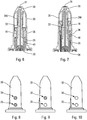
- the Figures 8 to 10 are schematic side views of the distribution head of the Figures 6 and 7 , showing the visual indication visible to the user, respectively before distribution of the first dose, after distribution of the first dose, and after distribution of the second dose.
- the dispensing device is a bidose which comprises a reservoir 10 containing two doses of fluid.
- a dispensing member such as a piston 20, is slidably mounted in said reservoir 10. In the position before actuation of the device, shown in FIG. figure 1 said piston 20 serves as a plug by isolating the contents of the reservoir 10.
- a dispensing head 30 is assembled on said reservoir 10 by being axially displaceable relative thereto.
- an axial displacement of the dispensing head 30 relative to the reservoir 10 causes the displacement of the piston 20 in the reservoir 10 and thus the distribution of the fluid contained in said reservoir.
- the dispensing head 30 has a dispensing channel 33 which leads from a piercing point 34 to the dispensing orifice 31 of the dispensing head 30. Upstream of the dispensing orifice 31, a dispensing channel 31 can be provided.
- spray profile 39 which may be of any known type and which is not shown in more detail in the drawings, for dispensing the fluid product in spray form.
- the dispensing head 30 has a lower side skirt 32 adapted to cooperate with an actuating member 60.
- a finger rest member 80 may be assembled around said dispensing head 30, or alternatively be formed integrally therewith.
- Said actuating member 60 is axially displaceable inside said lateral skirt 32 of the dispensing head 30 to perform the successive actuations of the device.
- the actuating member 60 comprises at least one inclined lug 61 which is adapted to cooperate with projections 51, 52 of the body 50 to perform the successive actuations.
- the device After dispensing the first dose, the device is in the position shown on the figure 2 and when the user releases the actuating member 60, the spring 70 will bring it back to its starting position. During this return of the actuating member 60, the reservoir and the body 50 do not return back, because these two components remain held in said dispensing head 30.
- the dispensing head 30 may comprise anti-rotation means. return to prevent a return of said body 50 and / or said tank 10 back.
- the actuating member 60 returns under the effect of the return spring 70 to its rest position, the tabs 61 will snap under the second projection 52 of the body 50 which will allow the user to operate a second time the device to dispense the second dose of fluid.
- this indicator 40 comprises at least one colored zone which will come to appear behind the viewing windows 35, 36 after the successive actuations of the device.
- the indicator 40 After dispensing the first dose, as shown in FIG. figure 2 , the indicator 40 has moved relative to the dispensing head 30 to be placed behind the first viewing window 35.
- the colored zone, typically red, of the indicator 40 will therefore indicate to the In the first viewing window 35, the user has a red display that the first dose has been dispensed, while the display in the second viewing window 36 remains unchanged.
- said indicator 40 After distribution of the second dose, said indicator 40 has continued its axial displacement relative to the dispensing head 30 to be positioned behind the second viewing window 36.
- the indicator cooperates advantageously with the two viewing windows 35, 36, that is to say that the user will see the colored area in the two windows 35, 36.
- the two viewing windows 35, 36 have a display that appears blank, for example in white. After dispensing the first dose, the first viewing window 35 becomes red, while the second viewing window 36 is still blank. After the distribution of the second dose, the two viewing windows 35, 36 are in red. The user therefore has no difficulty in seeing very quickly whether or not he has distributed the first and / or second dose, and therefore will not over-dose and / or under-dose the product, for example in distributing the product twice in the same nostril.
- the indicator 40 hides the first viewing window 35, so that only the second viewing window 36 displays a colored dot, as visible on the figure 9 .
- the indicator 40 hides the two viewing windows 35 and 36, so that no viewing window no longer displays a colored dot, as shown in FIG. figure 10 .
- the indicator 40 also makes it possible to indicate an incomplete distribution, in particular by appropriately sizing the viewing windows 35, 36.
- the indicator 40 only complete dose distributions allow the indicator to completely fill the surface of said windows. Incomplete distribution will therefore be detectable by the user with only partial indication in the viewing window concerned.
Landscapes
- Health & Medical Sciences (AREA)
- Engineering & Computer Science (AREA)
- Life Sciences & Earth Sciences (AREA)
- General Health & Medical Sciences (AREA)
- Public Health (AREA)
- Veterinary Medicine (AREA)
- Anesthesiology (AREA)
- Biomedical Technology (AREA)
- Heart & Thoracic Surgery (AREA)
- Hematology (AREA)
- Animal Behavior & Ethology (AREA)
- Bioinformatics & Cheminformatics (AREA)
- Pulmonology (AREA)
- Mechanical Engineering (AREA)
- Otolaryngology (AREA)
- Biophysics (AREA)
- Containers And Packaging Bodies Having A Special Means To Remove Contents (AREA)
- Feeding, Discharge, Calcimining, Fusing, And Gas-Generation Devices (AREA)
- Medical Preparation Storing Or Oral Administration Devices (AREA)
Description
- La présente invention concerne un dispositif de distribution de produit fluide, et plus particulièrement un dispositif de type bidose.
- Par dispositif de distribution de type bidose, on entend un dispositif contenant deux doses de produit fluide à distribuer lors de deux actionnements successifs du dispositif de distribution.
- Les dispositifs de type bidose sont bien connus dans l'état de la technique. Ces dispositifs comportent généralement un réservoir contenant les deux doses de produit fluide à distribuer, et un organe de distribution, qui est généralement un piston, qui est monté coulissant dans ledit réservoir, et qui est déplacé pour distribuer le produit fluide contenu dans ledit réservoir. Lorsque le dispositif est un bidose, le déplacement du piston se fait en deux courses d'actionnement successives, de sorte qu'une première dose est distribuée lors d'un premier actionnement et une seconde dose est distribuée lors d'un deuxième actionnement. Avec ce type de dispositif de type bidose, il est parfois difficile pour l'utilisateur de savoir s'il a distribué une ou deux dose(s) avec son dispositif. Or, selon le type de produit fluide qui est distribué par le dispositif, notamment lorsqu'il s'agit d'un médicament, il peut être important d'éviter tout risque de sous-dosage et/ou de surdosage. Ainsi, par exemple, si le dispositif de type bidose est destiné à distribuer une dose respective dans chaque narine, il n'est généralement pas souhaitable que les deux doses soient distribuées dans la même narine. Or, un utilisateur qui aurait utilisé le dispositif pour distribuer une première dose dans sa première narine, et qui l'aurait ensuite reposé ou qui aurait été distrait, risquerait, s'il n'est pas certain d'avoir déjà utilisé le dispositif une première fois, de distribuer la seconde dose dans la même narine que la première dose. Ceci n'est généralement pas souhaitable. Ainsi, si l'on expulse deux fois le produit dans la même narine, l'excédent d'actif ne sera pas correctement absorbé par les tissus, voire repartira immédiatement de la narine en coulant, avec une perte évidente d'efficacité. De plus, aucune dose ne sera alors disponible pour la seconde narine. Les documents
EP 0 254 391 ,FR 2 625 981 US 6 708 846 ,EP 0 580 897 etUS 2005/015051 décrivent des dispositifs de l'état de la technique. - La présente invention a pour but de fournir un dispositif de distribution de produit fluide qui ne reproduit pas les inconvénients susmentionnés.
- La présente invention a ainsi pour but de fournir un dispositif de distribution de produit fluide qui indique de manière fiable à l'utilisateur le nombre de doses distribuées.
- La présente invention a également pour but de fournir un tel dispositif de distribution de produit fluide qui soit simple et peu coûteux à fabriquer et à assembler.
- La présente invention a donc pour objet un dispositif de distribution de produit fluide comportant un réservoir contenant au moins deux doses de produit fluide, un organe de distribution, tel qu'un piston, monté coulissant dans ledit réservoir pour distribuer du produit fluide, une tête de distribution pourvue d'un orifice de distribution, ladite tête étant déplaçable par rapport audit réservoir pour déplacer ledit organe d'actionnement dans ledit réservoir et ainsi distribuer du produit fluide à travers ledit orifice de distribution, ladite tête de distribution comportant au moins deux fenêtres de visualisation, ledit dispositif comportant un indicateur mobile ensemble avec ledit réservoir, ledit indicateur coopérant après chaque actionnement du dispositif avec une fenêtre de visualisation respective.
- Avantageusement, le réservoir contient deux doses de produit fluide, distribuées lors de deux actionnements successifs du dispositif, ladite tête de distribution comportant deux fenêtres de visualisation.
- Avantageusement, ledit indicateur coopère avec une première fenêtre de visualisation après distribution de la première dose de produit fluide, et avec une seconde fenêtre de visualisation après distribution de la seconde dose de produit fluide.
- Selon une première variante avantageuse, ledit indicateur comporte au moins une zone d'indication en couleur, ladite zone d'indication apparaissant dans ladite première fenêtre de visualisation après distribution de la première dose de produit fluide et dans la seconde fenêtre de visualisation après distribution de la seconde dose de produit fluide.
- Selon une seconde variante avantageuse, ledit indicateur est adapté à masquer des zones d'indication en couleur prévues dans ladite tête de distribution, ledit indicateur masquant une zone d'indication en couleur dans ladite première fenêtre de visualisation après distribution de la première dose de produit fluide et masquant une zone d'indication en couleur dans ladite seconde fenêtre de visualisation après distribution de la seconde dose de produit fluide.
- Avantageusement, après distribution de la seconde dose de produit fluide, ledit indicateur coopère avec les deux fenêtres de visualisation.
- Avantageusement, ledit indicateur est formé sur un corps fixé audit réservoir.
- Avantageusement, ledit indicateur est adapté à indiquer une distribution de dose incomplète à travers au moins une fenêtre de visualisation.
- Ces avantages et caractéristiques et d'autres de la présente invention apparaîtront plus clairement au cours de la description détaillée suivante, faite en référence aux dessins joints, donnés à titre d'exemples non limitatifs, et sur lesquels
- Les
figures 1, 2 et 3 sont des vues schématiques en section transversale d'un dispositif de distribution de produit fluide selon une première variante de réalisation avantageuse de la présente invention, respectivement avant distribution de la première dose, après distribution de la première dose, et après distribution de la seconde dose, - La
figure 4 est une vue agrandie du détail A de lafigure 2 , - La
figure 5 est une vue agrandie du détail B de lafigure 3 , - Les
figures 6 et 7 sont des vues schématiques partiellement en section transversale d'une seconde variante de réalisation de l'invention, respectivement après distribution de la première dose et après distribution de la seconde dose, et - Les
figures 8 à 10 sont des vues schématiques de côté de la tête de distribution desfigures 6 et 7 , montrant l'indication visuelle visible par l'utilisateur, respectivement avant distribution de la première dose, après distribution de la première dose, et après distribution de la seconde dose. - La présente invention sera décrite ci-après en référence à un exemple de réalisation qui est un bidose, c'est-à-dire un dispositif contenant deux doses de produit fluide à distribuer lors de deux actionnements successifs du dispositif.
- En se référant aux
figures 1 à 3 , le dispositif de distribution est un bidose qui comporte un réservoir 10 contenant deux doses de produit fluide. Un organe de distribution, tel qu'un piston 20, est monté coulissant dans ledit réservoir 10. Dans la position avant actionnement du dispositif, représentée sur lafigure 1 , ledit piston 20 fait office de bouchon en isolant le contenu du réservoir 10. - Une tête de distribution 30 est assemblée sur ledit réservoir 10 en étant déplaçable axialement par rapport à celui-ci. En particulier, un déplacement axial de la tête de distribution 30 par rapport au réservoir 10 provoque le déplacement du piston 20 dans le réservoir 10 et ainsi la distribution du produit fluide contenu dans ledit réservoir. La tête de distribution 30 comporte un canal de distribution 33 qui mène depuis une pointe de percement 34 jusqu'à l'orifice de distribution 31 de la tête de distribution 30. En amont de l'orifice de distribution 31, il peut être prévu un profil de pulvérisation 39, qui peut être d'un quelconque type connu et qui n'est pas représenté plus en détail sur les dessins, pour distribuer le produit fluide sous forme de spray.
- Plus précisément, dans l'exemple représenté, le réservoir 10 est fixé dans un corps 50, qui est donc solidaire dudit réservoir 10, et qui se déplace ensemble avec lui.
- La tête de distribution 30 comporte une jupe latérale inférieure 32 adaptée à coopérer avec un organe d'actionnement 60. Un élément repose-doigts 80 peut être assemblé autour de ladite tête de distribution 30, ou en variante être formé de manière monobloc avec elle.
- Ledit organe d'actionnement 60 est axialement déplaçable à l'intérieur de ladite jupe latérale 32 de la tête de distribution 30 pour réaliser les actionnements successifs de dispositif. Comme visible notamment sur la
figure 1 , l'organe d'actionnement 60 comporte au moins une patte inclinée 61 qui est adaptée à coopérer avec des projections 51, 52 du corps 50 pour réaliser les actionnements successifs. - Un ressort de rappel 70 est monté entre l'organe d'actionnement 60 et la tête de distribution 30 pour ramener ledit organe d'actionnement 60 dans sa position de départ après chaque actionnement.
- Le fonctionnement du dispositif représenté sur les
figures 1 à 3 est le suivant. Dans la position de repos de lafigure 1 , le piston bouchon 20 isole le contenu du réservoir 10 de l'atmosphère. Lorsque l'utilisateur appuie simultanément sur le repose-doigt 80 et sur l'organe d'actionnement 60, il va déplacer ledit organe d'actionnement 60 à l'intérieur de la jupe latérale 32 de la tête de distribution 30. Ceci va pousser le corps 50 axialement vers le haut à partir de la position représentée sur lafigure 1 , par l'intermédiaire des pattes 61 qui vont pousser sur l'épaulement 51 dudit corps. Ceci va comprimer le ressort 70 et déplacer le réservoir 10 par rapport à la tête de distribution 30. Lorsque le réservoir 10 va commencer à se déplacer par rapport à la tête de distribution 30, l'extrémité de percement 34 du canal de distribution 33 va venir percer le piston de bouchon 20 pour faire communiquer l'intérieur du réservoir 10 avec ledit canal d'expulsion 33. Une poursuite de l'actionnement va provoquer un déplacement du piston 20 à l'intérieur du réservoir et donc une distribution de la première dose. Le produit fluide est donc poussé par ledit piston 20 à travers l'extrémité de percement 34 dans le canal de distribution 33, puis via le profil de pulvérisation 39, hors du dispositif à travers l'orifice de distribution 31. - Après distribution de la première dose, le dispositif est dans la position représentée sur la
figure 2 , et lorsque l'utilisateur relâche l'organe d'actionnement 60, le ressort 70 va ramener celui-ci vers sa position de départ. Pendant ce retour de l'organe d'actionnement 60, le réservoir et le corps 50 ne reviennent pas en arrière, car ces deux composants restent maintenus dans ladite tête de distribution 30. Eventuellement, la tête de distribution 30 peut comporter des moyens anti-retour pour empêcher un retour dudit corps 50 et/ou dudit réservoir 10 en arrière. Lorsque l'organe d'actionnement 60 revient sous l'effet du ressort de rappel 70 vers sa position de repos, les pattes 61 vont venir s'encliqueter sous la deuxième projection 52 du corps 50 ce qui va permettre à l'utilisateur d'actionner une deuxième fois le dispositif pour distribuer la deuxième dose de produit fluide. - La
figure 3 représente la position après distribution de la deuxième dose. - Selon l'invention, le dispositif de distribution comporte un indicateur 40 pour indiquer à l'utilisateur la distribution de la première dose et la distribution de la deuxième dose. De cette manière, l'utilisateur sait exactement où il en est et si la première dose a ou non été distribuée. Cet indicateur 40 est adapté à coopérer avec des fenêtres de visualisation 35, 36 formées dans ladite tête de distribution 30. Avantageusement, ces fenêtres de visualisation 35, 36 sont formées dans une paroi latérale de la tête bien visible de l'utilisateur lorsqu'il tient le dispositif dans sa main. Bien entendu, si le nombre de doses de produit fluide contenues dans le réservoir est différent de deux alors le nombre de fenêtres de visualisation sera également différent de deux. Ces fenêtres de visualisation peuvent notamment être réalisées sous la forme de trous traversants à travers la paroi de la tête de distribution 30, comme illustré sur les figures.
- Avantageusement, ledit indicateur 40 est formé sur ledit corps 50 qui est fixé au réservoir 10. Toutefois, en variante on pourrait imaginer un indicateur 40 formé directement sur le réservoir 10.
- Selon une première variante avantageuse, cet indicateur 40 comporte au moins une zone colorée qui va venir s'afficher derrière les fenêtres de visualisation 35, 36 après les actionnements successifs du dispositif.
- Ainsi, comme visible sur la
figure 1 , avant actionnement, aucune partie de l'indicateur 40 n'est visible derrière les fenêtres de visualisation 35, 36. Après distribution de la première dose, comme représenté sur lafigure 2 , l'indicateur 40 s'est déplacé par rapport à la tête de distribution 30 pour venir se placer derrière la première fenêtre de visualisation 35. Avantageusement, la zone colorée, typiquement en rouge, de l'indicateur 40 va donc indiquer à l'utilisateur par un affichage rouge dans la première fenêtre de visualisation 35 que la première dose a été distribuée, alors que l'affichage dans la seconde fenêtre de visualisation 36 reste inchangé. Après distribution de la seconde dose, ledit indicateur 40 a poursuivi son déplacement axial par rapport à la tête de distribution 30 pour venir se positionner derrière la seconde fenêtre de visualisation 36. Dans cette mise en oeuvre, après distribution de la deuxième dose, l'indicateur coopère avantageusement avec les deux fenêtres de visualisation 35, 36, c'est-à-dire que l'utilisateur verra la zone colorée dans les deux fenêtres 35, 36. - Ainsi pour résumer, avant le premier actionnement du dispositif, les deux fenêtres de visualisation 35, 36 ont un affichage qui apparaît vierge, par exemple en blanc. Après distribution de la première dose, la première fenêtre de visualisation 35 devient rouge, alors que la seconde fenêtre de visualisation 36 est toujours vierge. Après la distribution de la deuxième dose, les deux fenêtres de visualisation 35, 36 sont en rouge. L'utilisateur n'a donc aucune difficulté à voir très rapidement s'il a ou non distribué la première et/ou la seconde dose, et ne risquera donc pas de sur-doser et/ou sous-doser le produit, par exemple en distribuant le produit deux fois dans la même narine.
- Selon une seconde variante avantageuse, l'indicateur 40 ne comporte pas de zone coloré, mais est au contraire réalisé avec la même couleur que la tête de distribution 30. Dans cette seconde variante, l'indicateur 40 est adapté à masquer des zones d'indication en couleur visibles à travers les fenêtres de visualisation 35, 36 avant actionnement. Ainsi, les zones d'indication en couleur peuvent être prévues sur une pièce solidaire de la tête de distribution, notamment sur l'élément de tige 390 qui est en contact avec le piston 20. En particulier, cet élément de tige 390 peut être entièrement réalisé en matériau coloré. Le réservoir 10 est alors avantageusement transparent pour permettre la visualisation desdites zones d'indication en couleur dans les fenêtres de visualisation 35, 36 avant actionnement. Avant le premier actionnement, les deux fenêtres de visualisation 35 et 36 affichent un point coloré, comme visible sur la
figure 8 . Après le premier actionnement, l'indicateur 40 masque la première fenêtre de visualisation 35, de sorte que seule la seconde fenêtre de visualisation 36 affiche un point coloré, comme visible sur lafigure 9 . Après le second actionnement, l'indicateur 40 masque les deux fenêtres de visualisation 35 et 36, de sorte qu'aucune fenêtre de visualisation n'affiche plus de point coloré, comme représenté sur lafigure 10 . - Ainsi pour résumer, avant le premier actionnement du dispositif, les deux fenêtres de visualisation 35, 36 ont un affichage coloré, par exemple en rouge ou en bleu. Après distribution de la première dose, la zone colorée derrière la première fenêtre de visualisation 35 est masqué, alors que l'affichage de la seconde fenêtre de visualisation 36 reste inchangé. Après la distribution de la deuxième dose, les zones colorées derrière les deux fenêtres de visualisation 35, 36 sont masquées par l'indicateur 40. L'utilisateur n'a donc aucune difficulté à voir très rapidement s'il a ou non distribué la première et/ou la seconde dose, et ne risquera donc pas de sur-doser et/ou sous-doser le produit, par exemple en distribuant le produit deux fois dans la même narine.
- Avantageusement, l'indicateur 40 permet aussi d'indiquer une distribution incomplète, notamment en dimensionnant de manière appropriée les fenêtres de visualisation 35, 36. Ainsi, seule des distributions de doses complètes permettent à l'indicateur de remplir complètement la surface desdites fenêtres. Une distribution incomplète sera donc détectable par l'utilisateur grâce à une indication seulement partielle dans la fenêtre de visualisation concernée.
- Bien entendu, la présente invention a été décrite en référence à deux variantes de réalisation, qui ne sont pas limitatives, et toute modification utile peut être apportée à la présente invention sans sortir du cadre de celle-ci tel que défini par les revendications annexées.
Claims (7)
- Dispositif de distribution de produit fluide comportant un réservoir (10) contenant deux doses de produit fluide, un organe de distribution (20), formé par un piston, monté coulissant dans ledit réservoir (10) pour distribuer du produit fluide, ledit piston étant déplaçable par rapport audit réservoir entre une position de repos, avant distribution de la première dose, et une position finale, après distribution de la seconde dose, une tête de distribution (30) pourvue d'un orifice de distribution (31), ladite tête étant déplaçable par rapport audit réservoir (10) pour déplacer ledit organe d'actionnement (20) dans ledit réservoir (10) et ainsi distribuer du produit fluide à travers ledit orifice de distribution (31), caractérisé en ce que ladite tête de distribution (30) comporte deux fenêtres de visualisation (35, 36), ledit dispositif comportant un indicateur (40) mobile ensemble avec ledit réservoir (10), ledit indicateur (40) coopérant après chaque actionnement du dispositif avec une fenêtre de visualisation respective (35, 36).
- Dispositif selon la revendication 1, dans lequel ledit indicateur (40) coopère avec une première fenêtre de visualisation (35) après distribution de la première dose de produit fluide, et avec une seconde fenêtre de visualisation (36) après distribution de la seconde dose de produit fluide.
- Dispositif selon la revendication 2, dans lequel ledit indicateur (40) comporte au moins une zone d'indication en couleur, ladite zone d'indication apparaissant dans ladite première fenêtre de visualisation (35) après distribution de la première dose de produit fluide et dans la seconde fenêtre de visualisation (36) après distribution de la seconde dose de produit fluide.
- Dispositif selon la revendication 2, dans lequel ledit indicateur (40) est adapté à masquer des zones d'indication en couleur prévues dans ladite tête de distribution (30), ledit indicateur (40) masquant une zone d'indication en couleur dans ladite première fenêtre de visualisation (35) après distribution de la première dose de produit fluide et masquant une zone d'indication en couleur dans ladite seconde fenêtre de visualisation (36) après distribution de la seconde dose de produit fluide.
- Dispositif selon l'une quelconque des revendications 2 à 4, dans lequel, après distribution de la seconde dose de produit fluide, ledit indicateur (40) coopère avec les deux fenêtres de visualisation (35, 36).
- Dispositif selon l'une quelconque des revendications précédentes, dans lequel ledit indicateur (40) est formé sur un corps (50) fixé audit réservoir.
- Dispositif selon l'une quelconque des revendications précédentes, dans lequel ledit indicateur (40) est adapté à indiquer une distribution de dose incomplète à travers au moins une fenêtre de visualisation (35, 36).
Applications Claiming Priority (2)
| Application Number | Priority Date | Filing Date | Title |
|---|---|---|---|
| FR1352460A FR3003481B1 (fr) | 2013-03-19 | 2013-03-19 | Dispositif de distribution de produit fluide. |
| PCT/FR2014/050618 WO2014147329A1 (fr) | 2013-03-19 | 2014-03-18 | Dispositif de distribution de produit fluide |
Publications (2)
| Publication Number | Publication Date |
|---|---|
| EP2976121A1 EP2976121A1 (fr) | 2016-01-27 |
| EP2976121B1 true EP2976121B1 (fr) | 2017-07-26 |
Family
ID=48795668
Family Applications (1)
| Application Number | Title | Priority Date | Filing Date |
|---|---|---|---|
| EP14720644.5A Active EP2976121B1 (fr) | 2013-03-19 | 2014-03-18 | Dispositif de distribution de produit fluide |
Country Status (6)
| Country | Link |
|---|---|
| US (1) | US9555950B2 (fr) |
| EP (1) | EP2976121B1 (fr) |
| JP (1) | JP6337084B2 (fr) |
| CN (1) | CN105050644B (fr) |
| FR (1) | FR3003481B1 (fr) |
| WO (1) | WO2014147329A1 (fr) |
Cited By (1)
| Publication number | Priority date | Publication date | Assignee | Title |
|---|---|---|---|---|
| WO2022171969A1 (fr) * | 2021-02-15 | 2022-08-18 | Aptar France Sas | Tête de distribution pour dispositif de distribution nasale d'un produit fluide ou pulvérulent |
Families Citing this family (33)
| Publication number | Priority date | Publication date | Assignee | Title |
|---|---|---|---|---|
| WO2016058124A1 (fr) * | 2014-10-14 | 2016-04-21 | The Procter & Gamble Company | Article de distribution comprenant un piston avec élément indicateur |
| US10940274B2 (en) * | 2015-12-01 | 2021-03-09 | Cipla Limited | Nasal spray assembly |
| FR3050984B1 (fr) * | 2016-05-04 | 2020-05-15 | Aptar France Sas | Dispositif de distribution de produit fluide. |
| FR3052691B1 (fr) | 2016-06-20 | 2021-01-22 | Aptar France Sas | Dispositif de distribution de produit fluide. |
| EP3528872A2 (fr) * | 2016-10-21 | 2019-08-28 | Sanofi-Aventis Deutschland GmbH | Dispositif d'administration de médicament liquide |
| JP6558392B2 (ja) * | 2017-04-04 | 2019-08-14 | ニプロ株式会社 | シリンジ型噴出装置 |
| AT520006B1 (de) * | 2017-06-07 | 2021-08-15 | Primetals Technologies Austria GmbH | Kühlmitteldüse zum kühlen eines metallischen strangs in einer stranggussanlage |
| FR3068624B1 (fr) | 2017-07-06 | 2021-01-22 | Aptar France Sas | Dispositif de distribution de produit fluide. |
| US20200009081A1 (en) | 2017-09-13 | 2020-01-09 | Janssen Pharmaceutica N.V. | Delivery Of Esketamine For The Treatment Of Depression |
| FR3075650B1 (fr) | 2017-12-22 | 2020-01-03 | Aptar France Sas | Dispositif de distribution de produit fluide. |
| WO2019182745A1 (fr) | 2018-03-19 | 2019-09-26 | Bryn Pharma, LLC | Formulations pour la pulvérisation d'épinéphrine |
| CH714774B1 (de) * | 2018-05-08 | 2019-09-13 | Akroswiss Ag | Bi-Dosis Nasenspray. |
| EP4382149A3 (fr) * | 2018-05-08 | 2024-08-07 | Akroswiss AG | Pulvérisation nasale bi-dose |
| FR3081104B1 (fr) | 2018-05-18 | 2020-05-15 | Aptar France Sas | Dispositif de distribution de produit fluide. |
| FR3083721B1 (fr) * | 2018-07-12 | 2020-12-18 | Aptar France Sas | Dispositif de distribution de produit fluide et son procede de remplissage et de bouchage. |
| FR3088224B1 (fr) * | 2018-11-14 | 2023-01-13 | Aptar France Sas | Dispositif de distribution de produit fluide. |
| FR3101619B1 (fr) | 2019-10-07 | 2021-12-17 | Aptar France Sas | Procédé de remplissage d’un dispositif de distribution de produit fluide |
| MX2022005262A (es) * | 2019-11-01 | 2022-08-25 | Janssen Pharmaceutica Nv | Dispositivos de entrenamiento y métodos para simular el suministro intranasal de fármacos. |
| FR3102934B1 (fr) | 2019-11-12 | 2022-06-03 | Aptar France Sas | Dispositif de distribution de produit fluide |
| AU2021210405A1 (en) | 2020-01-22 | 2022-08-25 | Seelos Therapeutics, Inc. | Reducing side effects of NMDA antagonists |
| US11607216B2 (en) | 2020-05-06 | 2023-03-21 | Janssen Pharmaceuticals, Inc. | Adaptive responses from smart packaging of drug delivery absorbable adjuncts |
| US12051495B2 (en) | 2020-05-06 | 2024-07-30 | Janssen Pharmaceuticals, Inc. | Patient monitoring using drug administration devices |
| US12062423B2 (en) | 2020-05-06 | 2024-08-13 | Janssen Pharmaceuticals, Inc. | Drug administration devices that communicate with surgical hubs |
| FR3112292A1 (fr) | 2020-07-07 | 2022-01-14 | Aptar France Sas | Tête de pulvérisation et dispositif de distribution de produit fluide comportant une telle tête |
| US20240100267A1 (en) | 2020-09-01 | 2024-03-28 | Janssen Pharmaceutica Nv | Drug delivery devices with a multi-dispensing head |
| US20230263972A1 (en) | 2020-09-01 | 2023-08-24 | Janssen Pharmaceutica Nv | Drug delivery devices with on-board drug destruction |
| EP4208229A1 (fr) | 2020-09-01 | 2023-07-12 | JANSSEN Pharmaceutica NV | Dispositifs d'administration de médicament avec verrouillage avant l'administration du médicament |
| WO2022049136A1 (fr) | 2020-09-01 | 2022-03-10 | Janssen Pharmaceutica Nv | Systèmes et procédés d'administration de médicament et médicaments |
| FR3115210B1 (fr) | 2020-10-20 | 2024-05-17 | Aptar France Sas | Dispositif de distribution de produit fluide |
| FR3116203B1 (fr) | 2020-11-13 | 2023-01-13 | Aptar France Sas | Dispositif de distribution de produit fluide |
| FR3120534B1 (fr) | 2021-03-09 | 2023-06-30 | Aptar France Sas | Tête de distribution nasale de produit fluide et dispositif comportant une telle tête |
| US20240261236A1 (en) | 2021-05-14 | 2024-08-08 | Seelos Therapeutics, Inc. | Methods of using nmda receptor antagonists |
| FR3129304B1 (fr) | 2021-11-24 | 2023-11-10 | Aptar France Sas | Dispositif de distribution de produit fluide |
Family Cites Families (18)
| Publication number | Priority date | Publication date | Assignee | Title |
|---|---|---|---|---|
| GB8610121D0 (en) * | 1986-04-25 | 1986-05-29 | Glaxo Group Ltd | Medical aerosol devices |
| AU598250B2 (en) * | 1986-04-25 | 1990-06-21 | Glaxo Group Limited | Indicating device |
| FR2625981B1 (fr) * | 1988-01-15 | 1990-04-27 | Valois Sa | Dispositif de pulverisation du contenu d'une ampoule cylindrique |
| FR2652981A1 (fr) | 1989-10-05 | 1991-04-12 | Centre Nat Rech Scient | Generateur de plasma a cathode creuse pour le traitement de poudres par plasma. |
| DK544589D0 (da) * | 1989-11-01 | 1989-11-01 | Novo Nordisk As | Manuel betjent apparat til dispensering af en forudbestemt maengde af et pulverformet stof |
| IT1260526B (it) * | 1992-06-03 | 1996-04-09 | Andrea Marelli | Erogatore nasale monodose di farmaci liquidi polverizzati |
| DE69918267T2 (de) * | 1998-01-16 | 2005-07-28 | 1263152 Ontario Inc., London | Anzeigevorrichtung zur verwendung mit einer abgabevorrichtung |
| US6142339A (en) * | 1998-01-16 | 2000-11-07 | 1263152 Ontario Inc. | Aerosol dispensing device |
| US6708846B1 (en) * | 1999-02-14 | 2004-03-23 | Ing. Erich Pfeiffer Gmbh | Dispenser for flowable media |
| IT1312426B1 (it) * | 1999-06-30 | 2002-04-17 | Microspray Delta Spa | Distributore di dosi di un liquido,con dispositivo per il conteggio di un elevato numero di dosi erogate |
| US6382204B1 (en) * | 1999-10-14 | 2002-05-07 | Becton Dickinson And Company | Drug delivery system including holder and drug container |
| GB0210605D0 (en) * | 2002-05-09 | 2002-06-19 | Glaxo Group Ltd | A fluid dispensing device |
| DE10323603A1 (de) * | 2003-05-20 | 2004-12-30 | Ing. Erich Pfeiffer Gmbh | Dosiervorrichtung mit einer Pumpeinrichtung |
| US7882982B2 (en) * | 2004-04-29 | 2011-02-08 | Valois Sas | Indicator for a device for dispensing a liquid or powdery product |
| FR2879574B1 (fr) * | 2004-12-17 | 2011-01-21 | Valois Sas | Dispositif de distribution de produit fluide. |
| CA2741281A1 (fr) * | 2008-11-03 | 2010-06-03 | Schering Corporation | Contenant bloquant la lumiere et comportant une fenetre de visualisation pour composes photosensibles |
| DE202008017185U1 (de) * | 2008-12-30 | 2010-05-12 | Siegfried Generics International Ag | Dosiervorrichtung |
| FR2952042B1 (fr) * | 2009-11-03 | 2012-01-20 | Valois Sas | Dispositif de distribution de produit fluide. |
-
2013
- 2013-03-19 FR FR1352460A patent/FR3003481B1/fr active Active
-
2014
- 2014-03-18 CN CN201480016656.0A patent/CN105050644B/zh active Active
- 2014-03-18 JP JP2016503704A patent/JP6337084B2/ja active Active
- 2014-03-18 EP EP14720644.5A patent/EP2976121B1/fr active Active
- 2014-03-18 WO PCT/FR2014/050618 patent/WO2014147329A1/fr active Application Filing
- 2014-03-18 US US14/765,907 patent/US9555950B2/en active Active
Non-Patent Citations (1)
| Title |
|---|
| None * |
Cited By (2)
| Publication number | Priority date | Publication date | Assignee | Title |
|---|---|---|---|---|
| WO2022171969A1 (fr) * | 2021-02-15 | 2022-08-18 | Aptar France Sas | Tête de distribution pour dispositif de distribution nasale d'un produit fluide ou pulvérulent |
| FR3119772A1 (fr) * | 2021-02-15 | 2022-08-19 | Aptar France Sas | Tête de distribution pour dispositif de distribution nasale d’un produit fluide ou pulvérulent |
Also Published As
| Publication number | Publication date |
|---|---|
| FR3003481B1 (fr) | 2020-05-15 |
| CN105050644B (zh) | 2018-01-02 |
| JP2016516500A (ja) | 2016-06-09 |
| WO2014147329A1 (fr) | 2014-09-25 |
| US20160068326A1 (en) | 2016-03-10 |
| US9555950B2 (en) | 2017-01-31 |
| CN105050644A (zh) | 2015-11-11 |
| FR3003481A1 (fr) | 2014-09-26 |
| JP6337084B2 (ja) | 2018-06-06 |
| EP2976121A1 (fr) | 2016-01-27 |
Similar Documents
| Publication | Publication Date | Title |
|---|---|---|
| EP2976121B1 (fr) | Dispositif de distribution de produit fluide | |
| EP1315576B1 (fr) | Dispositif de distribution de produit fluide de type multidose | |
| EP4232127B1 (fr) | Dispositif de distribution de produit fluide | |
| EP1476253B1 (fr) | Dispositif de pulverisation a actionnement lateral | |
| EP1954403B1 (fr) | Pompe de distribution de produit fluide | |
| EP1456098B1 (fr) | Dispositif de pulverisation a actionnement lateral | |
| EP3648897B1 (fr) | Dispositif de distribution de produit fluide. | |
| EP3727534B1 (fr) | Dispositif de distribution de produit fluide | |
| FR3036966A1 (fr) | Autoinjecteur | |
| FR3109887A1 (fr) | Dispositif de distribution de produit fluide | |
| EP2496296B1 (fr) | Dispositif de distribution de produit fluide | |
| WO2003041872A1 (fr) | Dispositif de distribution de produit fluide | |
| WO2020099766A1 (fr) | Dispositif de distribution de produit fluide | |
| EP1497039B1 (fr) | Pompe de distribution de produit fluide | |
| EP3927403B1 (fr) | Dispositif de distribution de produit fluide | |
| EP3888797B1 (fr) | Dispositif de distribution de produit fluide | |
| FR2847834A1 (fr) | Dispositif de distribution de produit fluide | |
| FR3129304A1 (fr) | Dispositif de distribution de produit fluide | |
| FR3130623A1 (fr) | Dispositif de distribution de produit fluide |
Legal Events
| Date | Code | Title | Description |
|---|---|---|---|
| PUAI | Public reference made under article 153(3) epc to a published international application that has entered the european phase |
Free format text: ORIGINAL CODE: 0009012 |
|
| 17P | Request for examination filed |
Effective date: 20151016 |
|
| AK | Designated contracting states |
Kind code of ref document: A1 Designated state(s): AL AT BE BG CH CY CZ DE DK EE ES FI FR GB GR HR HU IE IS IT LI LT LU LV MC MK MT NL NO PL PT RO RS SE SI SK SM TR |
|
| AX | Request for extension of the european patent |
Extension state: BA ME |
|
| DAX | Request for extension of the european patent (deleted) | ||
| GRAP | Despatch of communication of intention to grant a patent |
Free format text: ORIGINAL CODE: EPIDOSNIGR1 |
|
| GRAJ | Information related to disapproval of communication of intention to grant by the applicant or resumption of examination proceedings by the epo deleted |
Free format text: ORIGINAL CODE: EPIDOSDIGR1 |
|
| INTG | Intention to grant announced |
Effective date: 20161116 |
|
| GRAP | Despatch of communication of intention to grant a patent |
Free format text: ORIGINAL CODE: EPIDOSNIGR1 |
|
| INTG | Intention to grant announced |
Effective date: 20161124 |
|
| INTG | Intention to grant announced |
Effective date: 20161129 |
|
| GRAJ | Information related to disapproval of communication of intention to grant by the applicant or resumption of examination proceedings by the epo deleted |
Free format text: ORIGINAL CODE: EPIDOSDIGR1 |
|
| INTG | Intention to grant announced |
Effective date: 20161209 |
|
| GRAP | Despatch of communication of intention to grant a patent |
Free format text: ORIGINAL CODE: EPIDOSNIGR1 |
|
| INTG | Intention to grant announced |
Effective date: 20161220 |
|
| GRAJ | Information related to disapproval of communication of intention to grant by the applicant or resumption of examination proceedings by the epo deleted |
Free format text: ORIGINAL CODE: EPIDOSDIGR1 |
|
| INTG | Intention to grant announced |
Effective date: 20170113 |
|
| GRAP | Despatch of communication of intention to grant a patent |
Free format text: ORIGINAL CODE: EPIDOSNIGR1 |
|
| INTC | Intention to grant announced (deleted) | ||
| INTG | Intention to grant announced |
Effective date: 20170216 |
|
| RIN1 | Information on inventor provided before grant (corrected) |
Inventor name: LE MANER, FRANCOIS Inventor name: CARRICO, SILVIO Inventor name: WOCHELE, MATTHIAS Inventor name: GREINER-PERTH, JUERGEN |
|
| GRAS | Grant fee paid |
Free format text: ORIGINAL CODE: EPIDOSNIGR3 |
|
| GRAA | (expected) grant |
Free format text: ORIGINAL CODE: 0009210 |
|
| AK | Designated contracting states |
Kind code of ref document: B1 Designated state(s): AL AT BE BG CH CY CZ DE DK EE ES FI FR GB GR HR HU IE IS IT LI LT LU LV MC MK MT NL NO PL PT RO RS SE SI SK SM TR |
|
| REG | Reference to a national code |
Ref country code: GB Ref legal event code: FG4D Free format text: NOT ENGLISH |
|
| REG | Reference to a national code |
Ref country code: CH Ref legal event code: EP |
|
| REG | Reference to a national code |
Ref country code: AT Ref legal event code: REF Ref document number: 911886 Country of ref document: AT Kind code of ref document: T Effective date: 20170815 |
|
| REG | Reference to a national code |
Ref country code: IE Ref legal event code: FG4D Free format text: LANGUAGE OF EP DOCUMENT: FRENCH |
|
| REG | Reference to a national code |
Ref country code: DE Ref legal event code: R096 Ref document number: 602014012265 Country of ref document: DE |
|
| REG | Reference to a national code |
Ref country code: NL Ref legal event code: MP Effective date: 20170726 |
|
| REG | Reference to a national code |
Ref country code: LT Ref legal event code: MG4D |
|
| REG | Reference to a national code |
Ref country code: AT Ref legal event code: MK05 Ref document number: 911886 Country of ref document: AT Kind code of ref document: T Effective date: 20170726 |
|
| PG25 | Lapsed in a contracting state [announced via postgrant information from national office to epo] |
Ref country code: SE Free format text: LAPSE BECAUSE OF FAILURE TO SUBMIT A TRANSLATION OF THE DESCRIPTION OR TO PAY THE FEE WITHIN THE PRESCRIBED TIME-LIMIT Effective date: 20170726 Ref country code: NO Free format text: LAPSE BECAUSE OF FAILURE TO SUBMIT A TRANSLATION OF THE DESCRIPTION OR TO PAY THE FEE WITHIN THE PRESCRIBED TIME-LIMIT Effective date: 20171026 Ref country code: NL Free format text: LAPSE BECAUSE OF FAILURE TO SUBMIT A TRANSLATION OF THE DESCRIPTION OR TO PAY THE FEE WITHIN THE PRESCRIBED TIME-LIMIT Effective date: 20170726 Ref country code: LT Free format text: LAPSE BECAUSE OF FAILURE TO SUBMIT A TRANSLATION OF THE DESCRIPTION OR TO PAY THE FEE WITHIN THE PRESCRIBED TIME-LIMIT Effective date: 20170726 Ref country code: FI Free format text: LAPSE BECAUSE OF FAILURE TO SUBMIT A TRANSLATION OF THE DESCRIPTION OR TO PAY THE FEE WITHIN THE PRESCRIBED TIME-LIMIT Effective date: 20170726 Ref country code: HR Free format text: LAPSE BECAUSE OF FAILURE TO SUBMIT A TRANSLATION OF THE DESCRIPTION OR TO PAY THE FEE WITHIN THE PRESCRIBED TIME-LIMIT Effective date: 20170726 Ref country code: AT Free format text: LAPSE BECAUSE OF FAILURE TO SUBMIT A TRANSLATION OF THE DESCRIPTION OR TO PAY THE FEE WITHIN THE PRESCRIBED TIME-LIMIT Effective date: 20170726 |
|
| PG25 | Lapsed in a contracting state [announced via postgrant information from national office to epo] |
Ref country code: LV Free format text: LAPSE BECAUSE OF FAILURE TO SUBMIT A TRANSLATION OF THE DESCRIPTION OR TO PAY THE FEE WITHIN THE PRESCRIBED TIME-LIMIT Effective date: 20170726 Ref country code: GR Free format text: LAPSE BECAUSE OF FAILURE TO SUBMIT A TRANSLATION OF THE DESCRIPTION OR TO PAY THE FEE WITHIN THE PRESCRIBED TIME-LIMIT Effective date: 20171027 Ref country code: BG Free format text: LAPSE BECAUSE OF FAILURE TO SUBMIT A TRANSLATION OF THE DESCRIPTION OR TO PAY THE FEE WITHIN THE PRESCRIBED TIME-LIMIT Effective date: 20171026 Ref country code: ES Free format text: LAPSE BECAUSE OF FAILURE TO SUBMIT A TRANSLATION OF THE DESCRIPTION OR TO PAY THE FEE WITHIN THE PRESCRIBED TIME-LIMIT Effective date: 20170726 Ref country code: IS Free format text: LAPSE BECAUSE OF FAILURE TO SUBMIT A TRANSLATION OF THE DESCRIPTION OR TO PAY THE FEE WITHIN THE PRESCRIBED TIME-LIMIT Effective date: 20171126 Ref country code: PL Free format text: LAPSE BECAUSE OF FAILURE TO SUBMIT A TRANSLATION OF THE DESCRIPTION OR TO PAY THE FEE WITHIN THE PRESCRIBED TIME-LIMIT Effective date: 20170726 Ref country code: RS Free format text: LAPSE BECAUSE OF FAILURE TO SUBMIT A TRANSLATION OF THE DESCRIPTION OR TO PAY THE FEE WITHIN THE PRESCRIBED TIME-LIMIT Effective date: 20170726 |
|
| REG | Reference to a national code |
Ref country code: FR Ref legal event code: PLFP Year of fee payment: 5 |
|
| PG25 | Lapsed in a contracting state [announced via postgrant information from national office to epo] |
Ref country code: RO Free format text: LAPSE BECAUSE OF FAILURE TO SUBMIT A TRANSLATION OF THE DESCRIPTION OR TO PAY THE FEE WITHIN THE PRESCRIBED TIME-LIMIT Effective date: 20170726 Ref country code: CZ Free format text: LAPSE BECAUSE OF FAILURE TO SUBMIT A TRANSLATION OF THE DESCRIPTION OR TO PAY THE FEE WITHIN THE PRESCRIBED TIME-LIMIT Effective date: 20170726 Ref country code: DK Free format text: LAPSE BECAUSE OF FAILURE TO SUBMIT A TRANSLATION OF THE DESCRIPTION OR TO PAY THE FEE WITHIN THE PRESCRIBED TIME-LIMIT Effective date: 20170726 |
|
| REG | Reference to a national code |
Ref country code: DE Ref legal event code: R097 Ref document number: 602014012265 Country of ref document: DE |
|
| PG25 | Lapsed in a contracting state [announced via postgrant information from national office to epo] |
Ref country code: EE Free format text: LAPSE BECAUSE OF FAILURE TO SUBMIT A TRANSLATION OF THE DESCRIPTION OR TO PAY THE FEE WITHIN THE PRESCRIBED TIME-LIMIT Effective date: 20170726 Ref country code: SM Free format text: LAPSE BECAUSE OF FAILURE TO SUBMIT A TRANSLATION OF THE DESCRIPTION OR TO PAY THE FEE WITHIN THE PRESCRIBED TIME-LIMIT Effective date: 20170726 Ref country code: SK Free format text: LAPSE BECAUSE OF FAILURE TO SUBMIT A TRANSLATION OF THE DESCRIPTION OR TO PAY THE FEE WITHIN THE PRESCRIBED TIME-LIMIT Effective date: 20170726 |
|
| PLBE | No opposition filed within time limit |
Free format text: ORIGINAL CODE: 0009261 |
|
| STAA | Information on the status of an ep patent application or granted ep patent |
Free format text: STATUS: NO OPPOSITION FILED WITHIN TIME LIMIT |
|
| 26N | No opposition filed |
Effective date: 20180430 |
|
| PG25 | Lapsed in a contracting state [announced via postgrant information from national office to epo] |
Ref country code: SI Free format text: LAPSE BECAUSE OF FAILURE TO SUBMIT A TRANSLATION OF THE DESCRIPTION OR TO PAY THE FEE WITHIN THE PRESCRIBED TIME-LIMIT Effective date: 20170726 |
|
| PG25 | Lapsed in a contracting state [announced via postgrant information from national office to epo] |
Ref country code: MT Free format text: LAPSE BECAUSE OF FAILURE TO SUBMIT A TRANSLATION OF THE DESCRIPTION OR TO PAY THE FEE WITHIN THE PRESCRIBED TIME-LIMIT Effective date: 20170726 |
|
| REG | Reference to a national code |
Ref country code: CH Ref legal event code: PL |
|
| PG25 | Lapsed in a contracting state [announced via postgrant information from national office to epo] |
Ref country code: MC Free format text: LAPSE BECAUSE OF FAILURE TO SUBMIT A TRANSLATION OF THE DESCRIPTION OR TO PAY THE FEE WITHIN THE PRESCRIBED TIME-LIMIT Effective date: 20170726 |
|
| REG | Reference to a national code |
Ref country code: BE Ref legal event code: MM Effective date: 20180331 |
|
| REG | Reference to a national code |
Ref country code: IE Ref legal event code: MM4A |
|
| PG25 | Lapsed in a contracting state [announced via postgrant information from national office to epo] |
Ref country code: LU Free format text: LAPSE BECAUSE OF NON-PAYMENT OF DUE FEES Effective date: 20180318 |
|
| PG25 | Lapsed in a contracting state [announced via postgrant information from national office to epo] |
Ref country code: IE Free format text: LAPSE BECAUSE OF NON-PAYMENT OF DUE FEES Effective date: 20180318 |
|
| PG25 | Lapsed in a contracting state [announced via postgrant information from national office to epo] |
Ref country code: BE Free format text: LAPSE BECAUSE OF NON-PAYMENT OF DUE FEES Effective date: 20180331 Ref country code: CH Free format text: LAPSE BECAUSE OF NON-PAYMENT OF DUE FEES Effective date: 20180331 Ref country code: LI Free format text: LAPSE BECAUSE OF NON-PAYMENT OF DUE FEES Effective date: 20180331 |
|
| PG25 | Lapsed in a contracting state [announced via postgrant information from national office to epo] |
Ref country code: TR Free format text: LAPSE BECAUSE OF FAILURE TO SUBMIT A TRANSLATION OF THE DESCRIPTION OR TO PAY THE FEE WITHIN THE PRESCRIBED TIME-LIMIT Effective date: 20170726 |
|
| PG25 | Lapsed in a contracting state [announced via postgrant information from national office to epo] |
Ref country code: PT Free format text: LAPSE BECAUSE OF FAILURE TO SUBMIT A TRANSLATION OF THE DESCRIPTION OR TO PAY THE FEE WITHIN THE PRESCRIBED TIME-LIMIT Effective date: 20170726 |
|
| PG25 | Lapsed in a contracting state [announced via postgrant information from national office to epo] |
Ref country code: MK Free format text: LAPSE BECAUSE OF NON-PAYMENT OF DUE FEES Effective date: 20170726 Ref country code: CY Free format text: LAPSE BECAUSE OF FAILURE TO SUBMIT A TRANSLATION OF THE DESCRIPTION OR TO PAY THE FEE WITHIN THE PRESCRIBED TIME-LIMIT Effective date: 20170726 Ref country code: HU Free format text: LAPSE BECAUSE OF FAILURE TO SUBMIT A TRANSLATION OF THE DESCRIPTION OR TO PAY THE FEE WITHIN THE PRESCRIBED TIME-LIMIT; INVALID AB INITIO Effective date: 20140318 |
|
| PG25 | Lapsed in a contracting state [announced via postgrant information from national office to epo] |
Ref country code: AL Free format text: LAPSE BECAUSE OF FAILURE TO SUBMIT A TRANSLATION OF THE DESCRIPTION OR TO PAY THE FEE WITHIN THE PRESCRIBED TIME-LIMIT Effective date: 20170726 |
|
| P01 | Opt-out of the competence of the unified patent court (upc) registered |
Effective date: 20230526 |
|
| REG | Reference to a national code |
Ref country code: DE Ref legal event code: R082 Ref document number: 602014012265 Country of ref document: DE Representative=s name: SONNENBERG HARRISON PARTNERSCHAFT MBB PATENT- , DE |
|
| PGFP | Annual fee paid to national office [announced via postgrant information from national office to epo] |
Ref country code: DE Payment date: 20240307 Year of fee payment: 11 Ref country code: GB Payment date: 20240325 Year of fee payment: 11 |
|
| PGFP | Annual fee paid to national office [announced via postgrant information from national office to epo] |
Ref country code: IT Payment date: 20240312 Year of fee payment: 11 Ref country code: FR Payment date: 20240328 Year of fee payment: 11 |