EP2975351A1 - Additive manufactured surface finnish - Google Patents
Additive manufactured surface finnish Download PDFInfo
- Publication number
- EP2975351A1 EP2975351A1 EP15176665.6A EP15176665A EP2975351A1 EP 2975351 A1 EP2975351 A1 EP 2975351A1 EP 15176665 A EP15176665 A EP 15176665A EP 2975351 A1 EP2975351 A1 EP 2975351A1
- Authority
- EP
- European Patent Office
- Prior art keywords
- surface finish
- recited
- component
- heat transfer
- combustor
- Prior art date
- Legal status (The legal status is an assumption and is not a legal conclusion. Google has not performed a legal analysis and makes no representation as to the accuracy of the status listed.)
- Granted
Links
Images




Classifications
-
- F—MECHANICAL ENGINEERING; LIGHTING; HEATING; WEAPONS; BLASTING
- F28—HEAT EXCHANGE IN GENERAL
- F28F—DETAILS OF HEAT-EXCHANGE AND HEAT-TRANSFER APPARATUS, OF GENERAL APPLICATION
- F28F3/00—Plate-like or laminated elements; Assemblies of plate-like or laminated elements
- F28F3/02—Elements or assemblies thereof with means for increasing heat-transfer area, e.g. with fins, with recesses, with corrugations
- F28F3/04—Elements or assemblies thereof with means for increasing heat-transfer area, e.g. with fins, with recesses, with corrugations the means being integral with the element
-
- B—PERFORMING OPERATIONS; TRANSPORTING
- B22—CASTING; POWDER METALLURGY
- B22F—WORKING METALLIC POWDER; MANUFACTURE OF ARTICLES FROM METALLIC POWDER; MAKING METALLIC POWDER; APPARATUS OR DEVICES SPECIALLY ADAPTED FOR METALLIC POWDER
- B22F10/00—Additive manufacturing of workpieces or articles from metallic powder
- B22F10/20—Direct sintering or melting
- B22F10/25—Direct deposition of metal particles, e.g. direct metal deposition [DMD] or laser engineered net shaping [LENS]
-
- B—PERFORMING OPERATIONS; TRANSPORTING
- B22—CASTING; POWDER METALLURGY
- B22F—WORKING METALLIC POWDER; MANUFACTURE OF ARTICLES FROM METALLIC POWDER; MAKING METALLIC POWDER; APPARATUS OR DEVICES SPECIALLY ADAPTED FOR METALLIC POWDER
- B22F10/00—Additive manufacturing of workpieces or articles from metallic powder
- B22F10/20—Direct sintering or melting
- B22F10/28—Powder bed fusion, e.g. selective laser melting [SLM] or electron beam melting [EBM]
-
- B—PERFORMING OPERATIONS; TRANSPORTING
- B22—CASTING; POWDER METALLURGY
- B22F—WORKING METALLIC POWDER; MANUFACTURE OF ARTICLES FROM METALLIC POWDER; MAKING METALLIC POWDER; APPARATUS OR DEVICES SPECIALLY ADAPTED FOR METALLIC POWDER
- B22F10/00—Additive manufacturing of workpieces or articles from metallic powder
- B22F10/60—Treatment of workpieces or articles after build-up
- B22F10/66—Treatment of workpieces or articles after build-up by mechanical means
-
- F—MECHANICAL ENGINEERING; LIGHTING; HEATING; WEAPONS; BLASTING
- F23—COMBUSTION APPARATUS; COMBUSTION PROCESSES
- F23R—GENERATING COMBUSTION PRODUCTS OF HIGH PRESSURE OR HIGH VELOCITY, e.g. GAS-TURBINE COMBUSTION CHAMBERS
- F23R3/00—Continuous combustion chambers using liquid or gaseous fuel
- F23R3/002—Wall structures
-
- F—MECHANICAL ENGINEERING; LIGHTING; HEATING; WEAPONS; BLASTING
- F28—HEAT EXCHANGE IN GENERAL
- F28F—DETAILS OF HEAT-EXCHANGE AND HEAT-TRANSFER APPARATUS, OF GENERAL APPLICATION
- F28F13/00—Arrangements for modifying heat-transfer, e.g. increasing, decreasing
- F28F13/18—Arrangements for modifying heat-transfer, e.g. increasing, decreasing by applying coatings, e.g. radiation-absorbing, radiation-reflecting; by surface treatment, e.g. polishing
- F28F13/185—Heat-exchange surfaces provided with microstructures or with porous coatings
-
- B—PERFORMING OPERATIONS; TRANSPORTING
- B22—CASTING; POWDER METALLURGY
- B22F—WORKING METALLIC POWDER; MANUFACTURE OF ARTICLES FROM METALLIC POWDER; MAKING METALLIC POWDER; APPARATUS OR DEVICES SPECIALLY ADAPTED FOR METALLIC POWDER
- B22F5/00—Manufacture of workpieces or articles from metallic powder characterised by the special shape of the product
- B22F5/009—Manufacture of workpieces or articles from metallic powder characterised by the special shape of the product of turbine components other than turbine blades
-
- F—MECHANICAL ENGINEERING; LIGHTING; HEATING; WEAPONS; BLASTING
- F05—INDEXING SCHEMES RELATING TO ENGINES OR PUMPS IN VARIOUS SUBCLASSES OF CLASSES F01-F04
- F05B—INDEXING SCHEME RELATING TO WIND, SPRING, WEIGHT, INERTIA OR LIKE MOTORS, TO MACHINES OR ENGINES FOR LIQUIDS COVERED BY SUBCLASSES F03B, F03D AND F03G
- F05B2230/00—Manufacture
- F05B2230/30—Manufacture with deposition of material
-
- F—MECHANICAL ENGINEERING; LIGHTING; HEATING; WEAPONS; BLASTING
- F05—INDEXING SCHEMES RELATING TO ENGINES OR PUMPS IN VARIOUS SUBCLASSES OF CLASSES F01-F04
- F05D—INDEXING SCHEME FOR ASPECTS RELATING TO NON-POSITIVE-DISPLACEMENT MACHINES OR ENGINES, GAS-TURBINES OR JET-PROPULSION PLANTS
- F05D2230/00—Manufacture
- F05D2230/30—Manufacture with deposition of material
-
- F—MECHANICAL ENGINEERING; LIGHTING; HEATING; WEAPONS; BLASTING
- F23—COMBUSTION APPARATUS; COMBUSTION PROCESSES
- F23R—GENERATING COMBUSTION PRODUCTS OF HIGH PRESSURE OR HIGH VELOCITY, e.g. GAS-TURBINE COMBUSTION CHAMBERS
- F23R2900/00—Special features of, or arrangements for continuous combustion chambers; Combustion processes therefor
- F23R2900/00018—Manufacturing combustion chamber liners or subparts
-
- F—MECHANICAL ENGINEERING; LIGHTING; HEATING; WEAPONS; BLASTING
- F23—COMBUSTION APPARATUS; COMBUSTION PROCESSES
- F23R—GENERATING COMBUSTION PRODUCTS OF HIGH PRESSURE OR HIGH VELOCITY, e.g. GAS-TURBINE COMBUSTION CHAMBERS
- F23R2900/00—Special features of, or arrangements for continuous combustion chambers; Combustion processes therefor
- F23R2900/03042—Film cooled combustion chamber walls or domes
-
- F—MECHANICAL ENGINEERING; LIGHTING; HEATING; WEAPONS; BLASTING
- F23—COMBUSTION APPARATUS; COMBUSTION PROCESSES
- F23R—GENERATING COMBUSTION PRODUCTS OF HIGH PRESSURE OR HIGH VELOCITY, e.g. GAS-TURBINE COMBUSTION CHAMBERS
- F23R2900/00—Special features of, or arrangements for continuous combustion chambers; Combustion processes therefor
- F23R2900/03044—Impingement cooled combustion chamber walls or subassemblies
-
- F—MECHANICAL ENGINEERING; LIGHTING; HEATING; WEAPONS; BLASTING
- F28—HEAT EXCHANGE IN GENERAL
- F28F—DETAILS OF HEAT-EXCHANGE AND HEAT-TRANSFER APPARATUS, OF GENERAL APPLICATION
- F28F2255/00—Heat exchanger elements made of materials having special features or resulting from particular manufacturing processes
- F28F2255/18—Heat exchanger elements made of materials having special features or resulting from particular manufacturing processes sintered
-
- F—MECHANICAL ENGINEERING; LIGHTING; HEATING; WEAPONS; BLASTING
- F28—HEAT EXCHANGE IN GENERAL
- F28F—DETAILS OF HEAT-EXCHANGE AND HEAT-TRANSFER APPARATUS, OF GENERAL APPLICATION
- F28F2260/00—Heat exchangers or heat exchange elements having special size, e.g. microstructures
-
- Y—GENERAL TAGGING OF NEW TECHNOLOGICAL DEVELOPMENTS; GENERAL TAGGING OF CROSS-SECTIONAL TECHNOLOGIES SPANNING OVER SEVERAL SECTIONS OF THE IPC; TECHNICAL SUBJECTS COVERED BY FORMER USPC CROSS-REFERENCE ART COLLECTIONS [XRACs] AND DIGESTS
- Y02—TECHNOLOGIES OR APPLICATIONS FOR MITIGATION OR ADAPTATION AGAINST CLIMATE CHANGE
- Y02P—CLIMATE CHANGE MITIGATION TECHNOLOGIES IN THE PRODUCTION OR PROCESSING OF GOODS
- Y02P10/00—Technologies related to metal processing
- Y02P10/25—Process efficiency
-
- Y—GENERAL TAGGING OF NEW TECHNOLOGICAL DEVELOPMENTS; GENERAL TAGGING OF CROSS-SECTIONAL TECHNOLOGIES SPANNING OVER SEVERAL SECTIONS OF THE IPC; TECHNICAL SUBJECTS COVERED BY FORMER USPC CROSS-REFERENCE ART COLLECTIONS [XRACs] AND DIGESTS
- Y02—TECHNOLOGIES OR APPLICATIONS FOR MITIGATION OR ADAPTATION AGAINST CLIMATE CHANGE
- Y02T—CLIMATE CHANGE MITIGATION TECHNOLOGIES RELATED TO TRANSPORTATION
- Y02T50/00—Aeronautics or air transport
- Y02T50/60—Efficient propulsion technologies, e.g. for aircraft
Definitions
- the present disclosure relates to a gas turbine engine and, more particularly, to additive manufacturing control of a surface finish therefor.
- Gas turbine engines such as those that power modem commercial and military aircraft, generally include a compressor section to pressurize an airflow, a combustor section to burn a hydrocarbon fuel in the presence of the pressurized air, and a turbine section to extract energy from the resultant combustion gases.
- Combustors are subject to high thermal loads for prolonged time periods. Historically, combustors have implemented various cooling arrangements to cool the combustor liner assemblies. Among these is a double-walled assembly approach where liner panels directly adjacent to the combustion gases are cooled via impingement on the backside and film cooled on the gas side to maintain temperatures within material limits.
- liner panels are constructed of high-temperature alloys, e.g. nickel, cobalt, in the form of investment castings or elaborate sheet metal fabrications.
- the temperatures in the combustor often may exceed the temperature of the base metal so liner panels accommodate cooling holes to provide film cooling.
- the combustor shell may also include impingement cooling holes that introduce cooling air jets onto a back surface of the liner panels.
- surface augmentation on the back surface in the form of very small features such as pins, cylinders, pyramids and/or rectangular geometries may also be provided. These features offer an effective area increase for heat transfer. Optimization of features such as these is currently limited by reliability, accuracy, and cost of conventional manufacturing methods/tooling.
- An additively manufactured component according to one disclosed non-limiting embodiment of the present disclosure includes, a heat transfer augmentation feature with a surface finish between about 125 - 900 micro inches.
- a further embodiment of the present disclosure includes wherein the heat transfer augmentation feature may be a pin.
- the heat transfer augmentation feature is a fin.
- the surface finish includes a chevron.
- the surface finish includes a bump.
- the surface finish includes a hollow.
- the surface finish includes a dimple.
- the heat transfer augmentation feature includes a passage.
- the surface finish is arranged with respect to an airflow.
- An component according to another disclosed non-limiting embodiment of the present disclosure and which the Applicant expressly reserves the right to claim, includes an additively manufactured surface finish, said surface finish including a defined contour.
- the surface finish may be about between about 125 - 900 micro inches.
- the surface finish is on a heat transfer augmentation feature of the additively manufactured component.
- the surface finish may be on a heat transfer augmentation feature of the additively manufactured component.
- a method of manufacturing a component according to another disclosed non-limiting embodiment of the present disclosure includes an additively manufacturing a component with a surface finish having a defined contour.
- a further embodiment of the foregoing embodiment of the present disclosure includes applying the surface finish to a heat transfer augmentation feature of the additively manufactured component.
- a further embodiment of any of the foregoing embodiments of the present disclosure includes applying the surface finish to a fin of the additively manufactured component.
- a further embodiment of any of the foregoing embodiments of the present disclosure includes controlling the surface finish with respect to an airflow.
- a further embodiment of any of the foregoing embodiments of the present disclosure includes applying the surface finish within a passage.
- a further embodiment of any of the foregoing embodiments of the present disclosure includes controlling the surface finish to be within about 125 - 900 micro inches.
- FIG. 1 schematically illustrates a gas turbine engine 20.
- the gas turbine engine 20 is disclosed herein as a two-spool turbo fan that generally incorporates a fan section 22, a compressor section 24, a combustor section 26 and a turbine section 28.
- the fan section 22 drives air along a bypass flowpath and a core flowpath.
- the compressor section 24 compresses the air along the core flowpath for communication into the combustor section 26, then expansion through the turbine section 28.
- turbofan depicted as a turbofan in the disclosed non-limiting embodiment, it should be understood that the concepts described herein are not limited to use with turbofans as the teachings may be applied to other types of turbine engines such as a turbojets, turboshafts, and three-spool (plus fan) turbofans.
- the engine 20 generally includes a low spool 30 and a high spool 32 mounted for rotation about an engine central longitudinal axis A relative to an engine static structure 36.
- the low spool 30 generally includes an inner shaft 40 that interconnects a fan 42, a low pressure compressor (“LPC”) 44 and a low pressure turbine (“LPT”) 46.
- the inner shaft 40 drives the fan 42 directly or through a geared architecture 48 to drive the fan 42 at a lower speed than the low spool 30.
- An exemplary reduction transmission is an epicyclic transmission, namely a planetary or star gear system.
- the high spool 32 includes an outer shaft 50 that interconnects a high pressure compressor (“HPC”) 52 and high pressure turbine (“HPT”) 54.
- a combustor 56 is arranged between the HPC 52 and the HPT 54.
- the inner shaft 40 and the outer shaft 50 are concentric and rotate about the engine central longitudinal axis A.
- Core airflow is compressed by the LPC 44 then the HPC 52, mixed with the fuel and burned in the combustor 56, then expanded through the HPT 54 and the LPT 46.
- the LPT 46 and the HPT 54 rotationally drive the respective low spool 30 and high spool 32 in response to the expansion.
- the combustor 56 generally includes an outer combustor wall assembly 60, an inner combustor wall assembly 62 and a diffuser case module 64.
- the outer combustor wall assembly 60 and the inner combustor wall assembly 62 are spaced apart such that a combustion chamber 66 is defined therebetween.
- the combustion chamber 66 is generally annular in shape.
- the outer combustor wall assembly 60 is spaced radially inward from an outer diffuser case 64A of the diffuser case module 64 to define an outer annular plenum 76.
- the inner combustor wall assembly 62 is spaced radially outward from an inner diffuser case 64B of the diffuser case module 64 to define an inner annular plenum 78. It should be understood that although a particular combustor is illustrated, other combustor types with various combustor liner arrangements will also benefit herefrom.
- the combustor liner assemblies 60, 62 contain the combustion products for direction toward the turbine section 28.
- Each combustor wall assembly 60, 62 generally includes a respective support shell 68, 70 that supports one or more liner panels 72, 74 mounted to a hot side of the respective support shell 68, 70.
- Each of the liner panels 72, 74 may be generally rectilinear and manufactured of, for example, a nickel based super alloy, ceramic or other temperature resistant material and are arranged to form a liner array.
- the liner array includes a multiple of forward liner panels 72A and a multiple of aft liner panels 72B that are circumferentially staggered to line the hot side of the outer shell 68 (also shown in Figure 3 ).
- a multiple of forward liner panels 74A and a multiple of aft liner panels 74B are circumferentially staggered to line the hot side of the inner shell 70.
- the combustor 56 further includes a forward assembly 80 immediately downstream of the compressor section 24 to receive compressed airflow therefrom.
- the forward assembly 80 generally includes an annular hood 82, a bulkhead assembly 84, a multiple of fuel nozzles 86 (one shown) and a multiple of fuel nozzle guides 90 (one shown).
- Each of the fuel nozzle guides 90 is circumferentially aligned with one of the hood ports 94 to project through the bulkhead assembly 84.
- Each bulkhead assembly 84 includes a bulkhead support shell 96 secured to the combustor liner assemblies 60, 62, and a multiple of circumferentially distributed bulkhead liner panels 98 secured to the bulkhead support shell 96 around the central opening 92.
- the annular hood 82 extends radially between, and is secured to, the forwardmost ends of the combustor liner assemblies 60, 62.
- the annular hood 82 includes a multiple of circumferentially distributed hood ports 94 that accommodate the respective fuel nozzle 86 and introduce air into the forward end of the combustion chamber 66 through a central opening 92.
- Each fuel nozzle 86 may be secured to the diffuser case module 64 and project through one of the hood ports 94 and through the central opening 92 within the respective fuel nozzle guide 90.
- the forward assembly 80 introduces core combustion air into the forward section of the combustion chamber 66 while the remainder enters the outer annular plenum 76 and the inner annular plenum 78.
- the multiple of fuel nozzles 86 and adjacent structure generate a blended fuel-air mixture that supports stable combustion in the combustion chamber 66.
- the outer and inner support shells 68, 70 are mounted to a first row of Nozzle Guide Vanes (NGVs) 54A in the HPT 54.
- NGVs 54A are static engine components which direct core airflow combustion gases onto the turbine blades of the first turbine rotor in the turbine section 28 to facilitate the conversion of pressure energy into kinetic energy.
- the core airflow combustion gases are also accelerated by the NGVs 54A because of their convergent shape and are typically given a "spin” or a "swirl” in the direction of HPT rotor rotation.
- a multiple of studs 100 extend from the liner panels 72, 74 so as to permit the liner panels 72, 74 to be mounted to their respective support shells 68, 70 with fasteners 102 such as nuts. That is, the studs 100 project rigidly from the liner panels 72, 74 and through the respective support shells 68, 70 to receive the fasteners 102 at a threaded distal end section thereof.
- a multiple of cooling impingement holes 104 penetrate through the support shells 68, 70 to allow air from the respective annular plenums 76, 78 to enter cavities 106A, 106B formed in the combustor liner assemblies 60, 62 between the respective support shells 68, 70 and liner panels 72, 74.
- the cooling impingement holes 104 are generally normal to the surface of the liner panels 72, 74.
- the air in the cavities 106A, 106B provides backside impingement cooling of the liner panels 72, 74 that is generally defined herein as heat removal via internal convection.
- a multiple of cooling film holes 108 penetrate through each of the liner panels 72, 74.
- the geometry of the film holes e.g, diameter, shape, density, surface angle, incidence angle, etc., as well as the location of the holes with respect to the high temperature main flow also contributes to effusion film cooling.
- the combination of impingement holes 104 and film holes 108 may be referred to as an Impingement Film Floatwall assembly.
- the cooling film holes 108 allow the air to pass from the cavities 106A, 106B defined in part by a cold side 110 of the liner panels 72, 74 to a hot side 112 of the liner panels 72, 74 and thereby facilitate the formation of a film of cooling air along the hot side 112.
- the cooling film holes 108 are generally more numerous than the impingement holes 104 to promote the development of a film cooling along the hot side 112 to sheath the liner panels 72, 74.
- Film cooling as defined herein is the introduction of a relatively cooler airflow at one or more discrete locations along a surface exposed to a high temperature environment to protect that surface in the immediate region of the airflow injection as well as downstream thereof.
- a multiple of dilution holes 116 penetrate through both the respective support shells 68, 70 and liner panels 72, 74 along a common axis to quench or otherwise effect the hot gases by direct supply of cooling air into the combustion chamber 66.
- a multiple of heat transfer augmentation feature 118 extends from the cold side 110 of each liner panel 72, 74.
- Various shapes, heights, widths and lengths of heat transfer augmentation features 118 may be utilized.
- various distributions and combination of the heat transfer augmentation features 118 may be utilized in either or both the circumferential or spanwise direction.
- the support shells 68, 70 and liner panels 72, 74 are manufactured via an additive manufacturing process that beneficially permits incorporation of the relatively small heat transfer augmentation features 118 as well as the cooling impingement holes 104, the cooling film holes 108 and/or dilution holes 116 during manufacture.
- the additive manufacturing process includes, but is not limited to, Direct Selective Laser Sintering (DSLS), Electron Beam Sintering (EBS), Electron Beam Melting (EBM), Laser Engineered Net Shaping (LENS), Laser Net Shape Manufacturing (LNSM), Direct Metal Deposition (DMD) and Laser Powder Bed Fusion (LPBF).
- the additive manufacturing process sequentially builds-up layers of atomized alloy and/or ceramic powder material that include but are not limited to, 625 Alloy, 718 Alloy, 230 Alloy, stainless steel, tool steel, cobalt chrome, titanium, nickel, aluminum, Waspaloy, Stellite, Titanium, Steels, Stainless Steels, Cobalt Chrome, Hastalloy X, and others. Alloys such as 625, 718 and 230 may have specific benefit for parts that operate in high temperature environments, such as, for example, environments typically encountered by aerospace and gas turbine engine components.
- the heat transfer augmentation features 118 be they pins, cylinders, pyramids, rectangular and/or other geometries, as well as the holes 104, 108, 116 are thereby embedded in or inherent to the layered metal fabrication architecture.
- the heat transfer augmentation features 118 in one disclosed non-limiting embodiment, are between about 0.01" - 1.0" (0.254 - 25.4mm) in thickness or diameter. It should be appreciated that various geometries for what is generically defined herein as heat transfer augmentation features 118 will also benefit herefrom.
- the aforementioned techniques have the "print resolution" to melt, sinter or weld the powered metal in specific area and at target dimensions to provide the requisite heat transfer augmentation features 118.
- These techniques have layer resolution on the order of 20-50 microns which in adequate to generate well-defined shapes that have benefits as heat transfer augmentation features 118.
- Direct Metal Laser Sintering is a free form fabrication, powder-bed manufacturing process. Hardware is built up in a layer-by-layer fashion with a process that starts by slicing a CAD file into 20 ⁇ m (0.8 mils) or larger layers. This altered CAD file is loaded into the DMLS machine which builds the hardware one layer at a time, as defined by the new CAD file.
- Electron beam melting is a powder bed additive manufacturing process.
- EBM uses an electron beam to melt powdered metal deposited layer by layer in a vacuum to build up three dimensional parts.
- a CAD file is sliced into 50 ⁇ m or 70 ⁇ m (2.0 mils or 2.8 mils) thick layers, stored as STL files, which are then loaded into the EBM machine.
- An electron beam is generated by running a current through a tungsten filament, then creating a potential across it to rip off the electrons. The electrons are steered and focused to the build plate by magnetic fields. The lack of moving parts allows for very fast scanning speeds up to 8000 m/s.
- the surface finish 140 defines a surface roughness of texture that is a measure of the finer surface irregularities in the surface texture and is composed of three components: roughness, waviness and form. These are the result of the manufacturing process, here an additive manufacturing process, employed to create the surface.
- Surface roughness average (Ra) also know as arithmetic average (AA) is rated as the arithmetic average deviation of the surface valleys and peaks expressed in micro inches or micro meters.
- the desired surface finish 140 may be controlled via the additive manufacturing process. That is, for example, the heat transfer augmentation features 118 may be additively manufactured with a specific surface finish 140. Through control of the surface finish 140, the surface area is selectively controlled to thereby control airflow turbulence to tailor the heat transfer in a localized, or generalized manner.
- the surface finish 140 is controlled to be within about 125 - 900 micro inches.
- the desired surface finish 140 may be of a defined contours 142 such as fins ( Figure 6 ), pins ( Figure 7 ), hooks ( Figure 8 ), chevrons ( Figure 9 ), bumps ( Figure 10 ), dimples ( Figure 11 ), etc., that are defined with respect to an airflow ( Figure ).
- the surface finish 140 is applied within a passage 144.
- the surface finish 140 may be localized such as adjacent to a bend 146 to facilitate a flow therethrough.
- the surface finish 140 is applied to a fin 150.
- the fin 150 manufactured via additive manufacturing, may be about 0.02 inches (0.5mm) thick. It should be appreciated although one fin 150 is illustrated, numerous such fins may be additively manufactured as typical of a heat exchanger or other such device.
- Additively manufactured surface finish control is operable to, for example, optimized heat transfer, reduces manufacturing costs, reduce operations, increase part life, control local flow, control local turbulence and/or other structural benefits. It should be appreciated that although described herein with respect to particular components additive manufacturing control of a surface finish is readily applicable to any industry - aerospace, HVAC, automotive and industrial, power generation, motors, missiles/rockets, defense, electronic thermal management, etc.
Landscapes
- Engineering & Computer Science (AREA)
- Chemical & Material Sciences (AREA)
- Mechanical Engineering (AREA)
- General Engineering & Computer Science (AREA)
- Physics & Mathematics (AREA)
- Manufacturing & Machinery (AREA)
- Materials Engineering (AREA)
- Thermal Sciences (AREA)
- Combustion & Propulsion (AREA)
- Crystallography & Structural Chemistry (AREA)
- Plasma & Fusion (AREA)
- Turbine Rotor Nozzle Sealing (AREA)
- Powder Metallurgy (AREA)
Abstract
Description
- The present disclosure relates to a gas turbine engine and, more particularly, to additive manufacturing control of a surface finish therefor.
- Gas turbine engines, such as those that power modem commercial and military aircraft, generally include a compressor section to pressurize an airflow, a combustor section to burn a hydrocarbon fuel in the presence of the pressurized air, and a turbine section to extract energy from the resultant combustion gases.
- Combustors are subject to high thermal loads for prolonged time periods. Historically, combustors have implemented various cooling arrangements to cool the combustor liner assemblies. Among these is a double-walled assembly approach where liner panels directly adjacent to the combustion gases are cooled via impingement on the backside and film cooled on the gas side to maintain temperatures within material limits.
- Given the harsh thermal and operating environment, liner panels are constructed of high-temperature alloys, e.g. nickel, cobalt, in the form of investment castings or elaborate sheet metal fabrications. The temperatures in the combustor often may exceed the temperature of the base metal so liner panels accommodate cooling holes to provide film cooling. The combustor shell may also include impingement cooling holes that introduce cooling air jets onto a back surface of the liner panels.
- To still further increase cooling effectiveness, surface augmentation on the back surface in the form of very small features such as pins, cylinders, pyramids and/or rectangular geometries may also be provided. These features offer an effective area increase for heat transfer. Optimization of features such as these is currently limited by reliability, accuracy, and cost of conventional manufacturing methods/tooling.
- An additively manufactured component according to one disclosed non-limiting embodiment of the present disclosure includes, a heat transfer augmentation feature with a surface finish between about 125 - 900 micro inches.
- A further embodiment of the present disclosure includes wherein the heat transfer augmentation feature may be a pin.
- In a further embodiment of any of the foregoing embodiments of the present disclosure includes the heat transfer augmentation feature is a fin.
- In a further embodiment of any of the foregoing embodiments of the present disclosure includes wherein the surface finish includes a defined contour.
- In a further embodiment of any of the foregoing embodiments of the present disclosure, the surface finish includes a chevron.
- In a further embodiment of any of the foregoing embodiments of the present disclosure, the surface finish includes a bump.
- In a further embodiment of any of the foregoing embodiments of the present disclosure, the surface finish includes a hollow.
- In a further embodiment of any of the foregoing embodiments of the present disclosure, the surface finish includes a dimple.
- In a further embodiment of any of the foregoing embodiments of the present disclosure, the heat transfer augmentation feature includes a passage.
- In a further embodiment of any of the foregoing embodiments of the present disclosure, the surface finish is arranged with respect to an airflow.
- An component according to another disclosed non-limiting embodiment of the present disclosure and which the Applicant expressly reserves the right to claim, includes an additively manufactured surface finish, said surface finish including a defined contour.
- In an embodiment the foregoing embodiments of the present disclosure the surface finish may be about between about 125 - 900 micro inches.
- In a further embodiment of any of the foregoing embodiments of the present disclosure, the surface finish is on a heat transfer augmentation feature of the additively manufactured component.
- In a further embodiment of any of the foregoing embodiments of the present disclosure includes, the surface finish may be on a heat transfer augmentation feature of the additively manufactured component.
- A method of manufacturing a component according to another disclosed non-limiting embodiment of the present disclosure includes an additively manufacturing a component with a surface finish having a defined contour.
- A further embodiment of the foregoing embodiment of the present disclosure includes applying the surface finish to a heat transfer augmentation feature of the additively manufactured component.
- A further embodiment of any of the foregoing embodiments of the present disclosure includes applying the surface finish to a fin of the additively manufactured component.
- A further embodiment of any of the foregoing embodiments of the present disclosure includes controlling the surface finish with respect to an airflow.
- A further embodiment of any of the foregoing embodiments of the present disclosure includes applying the surface finish within a passage.
- A further embodiment of any of the foregoing embodiments of the present disclosure includes controlling the surface finish to be within about 125 - 900 micro inches.
- The foregoing features and elements may be combined in various combinations without exclusivity, unless expressly indicated otherwise. These features and elements as well as the operation of the invention will become more apparent in light of the following description and the accompanying drawings. It should be understood, however, the following description and drawings are intended to be exemplary in nature and non-limiting.
- Various features will become apparent to those skilled in the art from the following detailed description of the disclosed non-limiting embodiment. The drawings that accompany the detailed description can be briefly described as follows:
-
Figure 1 is a schematic cross-section of a gas turbine engine; -
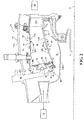
Figure 2 is an expanded longitudinal schematic sectional view of a combustor section according to one non-limiting embodiment that may be used with the gas turbine engine shown inFigure 1 ; -
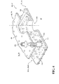
Figure 3 is an expanded perspective view of a liner panel array from a cold side; -
Figure 4 is an exploded view of a wall assembly of the combustor; -
Figure 5 is an expanded perspective view of an example surface finish; -
Figures 6-11 are schematic views of example surface finish contours for an additively manufactured component; -
Figure 12 is a schematic view of a passage with a localized additively manufactured surface finish; and -
Figure 13 is a schematic view of a heat transfer augmentation feature with an additively manufactured surface finish. -
Figure 1 schematically illustrates agas turbine engine 20. Thegas turbine engine 20 is disclosed herein as a two-spool turbo fan that generally incorporates afan section 22, acompressor section 24, acombustor section 26 and aturbine section 28. Thefan section 22 drives air along a bypass flowpath and a core flowpath. Thecompressor section 24 compresses the air along the core flowpath for communication into thecombustor section 26, then expansion through theturbine section 28. Although depicted as a turbofan in the disclosed non-limiting embodiment, it should be understood that the concepts described herein are not limited to use with turbofans as the teachings may be applied to other types of turbine engines such as a turbojets, turboshafts, and three-spool (plus fan) turbofans. - The
engine 20 generally includes alow spool 30 and ahigh spool 32 mounted for rotation about an engine central longitudinal axis A relative to an enginestatic structure 36. Thelow spool 30 generally includes aninner shaft 40 that interconnects afan 42, a low pressure compressor ("LPC") 44 and a low pressure turbine ("LPT") 46. Theinner shaft 40 drives thefan 42 directly or through a gearedarchitecture 48 to drive thefan 42 at a lower speed than thelow spool 30. An exemplary reduction transmission is an epicyclic transmission, namely a planetary or star gear system. - The
high spool 32 includes anouter shaft 50 that interconnects a high pressure compressor ("HPC") 52 and high pressure turbine ("HPT") 54. Acombustor 56 is arranged between the HPC 52 and the HPT 54. Theinner shaft 40 and theouter shaft 50 are concentric and rotate about the engine central longitudinal axis A. - Core airflow is compressed by the
LPC 44 then the HPC 52, mixed with the fuel and burned in thecombustor 56, then expanded through the HPT 54 and theLPT 46. TheLPT 46 and the HPT 54 rotationally drive the respectivelow spool 30 andhigh spool 32 in response to the expansion. - With reference to
Figure 2 , thecombustor 56 generally includes an outercombustor wall assembly 60, an innercombustor wall assembly 62 and adiffuser case module 64. The outercombustor wall assembly 60 and the innercombustor wall assembly 62 are spaced apart such that acombustion chamber 66 is defined therebetween. Thecombustion chamber 66 is generally annular in shape. - The outer
combustor wall assembly 60 is spaced radially inward from anouter diffuser case 64A of thediffuser case module 64 to define an outerannular plenum 76. The innercombustor wall assembly 62 is spaced radially outward from aninner diffuser case 64B of thediffuser case module 64 to define an innerannular plenum 78. It should be understood that although a particular combustor is illustrated, other combustor types with various combustor liner arrangements will also benefit herefrom. - The
combustor liner assemblies turbine section 28. Eachcombustor wall assembly respective support shell more liner panels 72, 74 mounted to a hot side of therespective support shell liner panels 72, 74 may be generally rectilinear and manufactured of, for example, a nickel based super alloy, ceramic or other temperature resistant material and are arranged to form a liner array. In one disclosed non-limiting embodiment, the liner array includes a multiple offorward liner panels 72A and a multiple of aft liner panels 72B that are circumferentially staggered to line the hot side of the outer shell 68 (also shown inFigure 3 ). A multiple offorward liner panels 74A and a multiple ofaft liner panels 74B are circumferentially staggered to line the hot side of theinner shell 70. - The
combustor 56 further includes aforward assembly 80 immediately downstream of thecompressor section 24 to receive compressed airflow therefrom. Theforward assembly 80 generally includes anannular hood 82, a bulkhead assembly 84, a multiple of fuel nozzles 86 (one shown) and a multiple of fuel nozzle guides 90 (one shown). Each of the fuel nozzle guides 90 is circumferentially aligned with one of thehood ports 94 to project through the bulkhead assembly 84. Each bulkhead assembly 84 includes abulkhead support shell 96 secured to thecombustor liner assemblies bulkhead support shell 96 around thecentral opening 92. - The
annular hood 82 extends radially between, and is secured to, the forwardmost ends of thecombustor liner assemblies annular hood 82 includes a multiple of circumferentially distributedhood ports 94 that accommodate therespective fuel nozzle 86 and introduce air into the forward end of thecombustion chamber 66 through acentral opening 92. Eachfuel nozzle 86 may be secured to thediffuser case module 64 and project through one of thehood ports 94 and through thecentral opening 92 within the respectivefuel nozzle guide 90. - The
forward assembly 80 introduces core combustion air into the forward section of thecombustion chamber 66 while the remainder enters the outerannular plenum 76 and the innerannular plenum 78. The multiple offuel nozzles 86 and adjacent structure generate a blended fuel-air mixture that supports stable combustion in thecombustion chamber 66. - Opposite the
forward assembly 80, the outer andinner support shells HPT 54. TheNGVs 54A are static engine components which direct core airflow combustion gases onto the turbine blades of the first turbine rotor in theturbine section 28 to facilitate the conversion of pressure energy into kinetic energy. The core airflow combustion gases are also accelerated by theNGVs 54A because of their convergent shape and are typically given a "spin" or a "swirl" in the direction of HPT rotor rotation. - With reference to
Figure 4 , a multiple ofstuds 100 extend from theliner panels 72, 74 so as to permit theliner panels 72, 74 to be mounted to theirrespective support shells fasteners 102 such as nuts. That is, thestuds 100 project rigidly from theliner panels 72, 74 and through therespective support shells fasteners 102 at a threaded distal end section thereof. - A multiple of cooling
impingement holes 104 penetrate through thesupport shells annular plenums cavities combustor liner assemblies respective support shells liner panels 72, 74. The cooling impingement holes 104 are generally normal to the surface of theliner panels 72, 74. The air in thecavities liner panels 72, 74 that is generally defined herein as heat removal via internal convection. - A multiple of cooling film holes 108 penetrate through each of the
liner panels 72, 74. The geometry of the film holes, e.g, diameter, shape, density, surface angle, incidence angle, etc., as well as the location of the holes with respect to the high temperature main flow also contributes to effusion film cooling. The combination of impingement holes 104 and film holes 108 may be referred to as an Impingement Film Floatwall assembly. - The cooling film holes 108 allow the air to pass from the
cavities cold side 110 of theliner panels 72, 74 to ahot side 112 of theliner panels 72, 74 and thereby facilitate the formation of a film of cooling air along thehot side 112. The cooling film holes 108 are generally more numerous than the impingement holes 104 to promote the development of a film cooling along thehot side 112 to sheath theliner panels 72, 74. Film cooling as defined herein is the introduction of a relatively cooler airflow at one or more discrete locations along a surface exposed to a high temperature environment to protect that surface in the immediate region of the airflow injection as well as downstream thereof. - A multiple of dilution holes 116 penetrate through both the
respective support shells liner panels 72, 74 along a common axis to quench or otherwise effect the hot gases by direct supply of cooling air into thecombustion chamber 66. - A multiple of heat
transfer augmentation feature 118 extends from thecold side 110 of eachliner panel 72, 74. Various shapes, heights, widths and lengths of heat transfer augmentation features 118 may be utilized. Furthermore, various distributions and combination of the heat transfer augmentation features 118 may be utilized in either or both the circumferential or spanwise direction. - The
support shells liner panels 72, 74, in this disclosed non-limiting example, are manufactured via an additive manufacturing process that beneficially permits incorporation of the relatively small heat transfer augmentation features 118 as well as the cooling impingement holes 104, the cooling film holes 108 and/or dilution holes 116 during manufacture. - The additive manufacturing process includes, but is not limited to, Direct Selective Laser Sintering (DSLS), Electron Beam Sintering (EBS), Electron Beam Melting (EBM), Laser Engineered Net Shaping (LENS), Laser Net Shape Manufacturing (LNSM), Direct Metal Deposition (DMD) and Laser Powder Bed Fusion (LPBF). The additive manufacturing process sequentially builds-up layers of atomized alloy and/or ceramic powder material that include but are not limited to, 625 Alloy, 718 Alloy, 230 Alloy, stainless steel, tool steel, cobalt chrome, titanium, nickel, aluminum, Waspaloy, Stellite, Titanium, Steels, Stainless Steels, Cobalt Chrome, Hastalloy X, and others. Alloys such as 625, 718 and 230 may have specific benefit for parts that operate in high temperature environments, such as, for example, environments typically encountered by aerospace and gas turbine engine components.
- The heat transfer augmentation features 118, be they pins, cylinders, pyramids, rectangular and/or other geometries, as well as the
holes - In other words, the aforementioned techniques have the "print resolution" to melt, sinter or weld the powered metal in specific area and at target dimensions to provide the requisite heat transfer augmentation features 118. These techniques have layer resolution on the order of 20-50 microns which in adequate to generate well-defined shapes that have benefits as heat transfer augmentation features 118. Direct Metal Laser Sintering (DMLS) is a free form fabrication, powder-bed manufacturing process. Hardware is built up in a layer-by-layer fashion with a process that starts by slicing a CAD file into 20µm (0.8 mils) or larger layers. This altered CAD file is loaded into the DMLS machine which builds the hardware one layer at a time, as defined by the new CAD file. Electron beam melting (EBM) is a powder bed additive manufacturing process. EBM, however, uses an electron beam to melt powdered metal deposited layer by layer in a vacuum to build up three dimensional parts. A CAD file is sliced into 50µm or 70µm (2.0 mils or 2.8 mils) thick layers, stored as STL files, which are then loaded into the EBM machine. An electron beam is generated by running a current through a tungsten filament, then creating a potential across it to rip off the electrons. The electrons are steered and focused to the build plate by magnetic fields. The lack of moving parts allows for very fast scanning speeds up to 8000 m/s.
- Utilization of the additive manufacturing process to manufacture components such as the
support shells liner panels 72, 74 also provides for specific control of a surface finish 140 (Figure 5 ). Thesurface finish 140 defines a surface roughness of texture that is a measure of the finer surface irregularities in the surface texture and is composed of three components: roughness, waviness and form. These are the result of the manufacturing process, here an additive manufacturing process, employed to create the surface. Surface roughness average (Ra), also know as arithmetic average (AA) is rated as the arithmetic average deviation of the surface valleys and peaks expressed in micro inches or micro meters. ISO standards use the term CLA (Center Line Average). As readily understood, 1 micro inch = .000001 inches (1 millionth of an inch). - In one disclosed non-limiting embodiment, the desired
surface finish 140 may be controlled via the additive manufacturing process. That is, for example, the heat transfer augmentation features 118 may be additively manufactured with aspecific surface finish 140. Through control of thesurface finish 140, the surface area is selectively controlled to thereby control airflow turbulence to tailor the heat transfer in a localized, or generalized manner. - While performing additive manufacturing, the
surface finish 140, in one disclosed non-limiting embodiment, is controlled to be within about 125 - 900 micro inches. Further, the desiredsurface finish 140 may be of a defined contours 142 such as fins (Figure 6 ), pins (Figure 7 ), hooks (Figure 8 ), chevrons (Figure 9 ), bumps (Figure 10 ), dimples (Figure 11 ), etc., that are defined with respect to an airflow (Figure ). - With reference to
Figure 12 , in one disclosed non-limiting embodiment, thesurface finish 140 is applied within apassage 144. Thesurface finish 140 may be localized such as adjacent to abend 146 to facilitate a flow therethrough. - With reference to
Figure 13 , in another disclosed non-limiting embodiment, thesurface finish 140 is applied to afin 150. Thefin 150, manufactured via additive manufacturing, may be about 0.02 inches (0.5mm) thick. It should be appreciated although onefin 150 is illustrated, numerous such fins may be additively manufactured as typical of a heat exchanger or other such device. - Additively manufactured surface finish control is operable to, for example, optimized heat transfer, reduces manufacturing costs, reduce operations, increase part life, control local flow, control local turbulence and/or other structural benefits. It should be appreciated that although described herein with respect to particular components additive manufacturing control of a surface finish is readily applicable to any industry - aerospace, HVAC, automotive and industrial, power generation, motors, missiles/rockets, defense, electronic thermal management, etc.
- The use of the terms "a," "an," "the," and similar references in the context of description (especially in the context of the following claims) are to be construed to cover both the singular and the plural, unless otherwise indicated herein or specifically contradicted by context. The modifier "about" used in connection with a quantity is inclusive of the stated value and has the meaning dictated by the context (e.g., it includes the degree of error associated with measurement of the particular quantity). All ranges disclosed herein are inclusive of the endpoints, and the endpoints are independently combinable with each other.
- Although the different non-limiting embodiments have specific illustrated components, the embodiments of this invention are not limited to those particular combinations. It is possible to use some of the components or features from any of the non-limiting embodiments in combination with features or components from any of the other non-limiting embodiments.
- It should be appreciated that like reference numerals identify corresponding or similar elements throughout the several drawings. It should also be appreciated that although a particular component arrangement is disclosed in the illustrated embodiment, other arrangements will benefit herefrom.
- Although particular step sequences are shown, described, and claimed, it should be understood that steps may be performed in any order, separated or combined unless otherwise indicated and will still benefit from the present disclosure.
- The foregoing description is exemplary rather than defined by the limitations within. Various non-limiting embodiments are disclosed herein, however, one of ordinary skill in the art would recognize that various modifications and variations in light of the above teachings will fall within the scope of the appended claims. It is therefore to be appreciated that within the scope of the appended claims, the disclosure may be practiced other than as specifically described. For that reason the appended claims should be studied to determine true scope and content.
Claims (15)
- An additively manufactured component, comprising:a heat transfer augmentation feature (140) with a surface finish between about 125 - 900 micro inches.
- The component as recited in claim 1, wherein said heat transfer augmentation feature is a pin (140B).
- The component as recited in claim 1, wherein said heat transfer augmentation feature is a fin (140A).
- The component as recited in claim 1, wherein said surface finish includes a defined contour.
- The component as recited in claim 4, wherein said surface finish includes a chevron (140D).
- The component as recited in claim 4, wherein said surface finish includes a bump (140E).
- The component as recited in claim 4, wherein said surface finish includes a hollow (140F).
- The component as recited in claim 4, wherein said surface finish includes a dimple (140F).
- The component as recited in any preceding claim, wherein said heat transfer augmentation feature includes a passage (144).
- A method of manufacturing a component, comprising:additively manufacturing a component with a surface finish having a defined contour.
- The method as recited in claim 10, further comprising:applying the surface finish to a heat transfer augmentation feature (140) of the additively manufactured component.
- The method as recited in claim 10 or 11, further comprising:applying the surface finish to a fin (140A) of the additively manufactured component.
- The method as recited in any of claims 10 to 12, further comprising:controlling the surface finish with respect to an airflow.
- The method as recited in any of claims 10 to 13, further comprising:applying the surface finish within a passage (144).
- The method as recited in any of claims 10 to 14, further comprising:controlling the surface finish to be within about 125 - 900 micro inches.
Applications Claiming Priority (1)
| Application Number | Priority Date | Filing Date | Title |
|---|---|---|---|
| US201462024023P | 2014-07-14 | 2014-07-14 |
Publications (2)
| Publication Number | Publication Date |
|---|---|
| EP2975351A1 true EP2975351A1 (en) | 2016-01-20 |
| EP2975351B1 EP2975351B1 (en) | 2023-11-01 |
Family
ID=53938056
Family Applications (1)
| Application Number | Title | Priority Date | Filing Date |
|---|---|---|---|
| EP15176665.6A Active EP2975351B1 (en) | 2014-07-14 | 2015-07-14 | Additive manufactured surface finnish |
Country Status (5)
| Country | Link |
|---|---|
| US (1) | US10807163B2 (en) |
| EP (1) | EP2975351B1 (en) |
| JP (1) | JP6470135B2 (en) |
| CN (1) | CN105258159B (en) |
| AU (1) | AU2015204269B2 (en) |
Cited By (5)
| Publication number | Priority date | Publication date | Assignee | Title |
|---|---|---|---|---|
| EP3056302A1 (en) * | 2015-02-12 | 2016-08-17 | United Technologies Corporation | Anti-deflection feature for additively manufactured thin metal parts and method of additively manufacturing thin metal parts |
| FR3064509A1 (en) * | 2017-03-28 | 2018-10-05 | Safran Aircraft Engines | DEVICE FOR ADDITIVE MANUFACTURING OF TURBOMACHINE PIECE BY DIRECT DEPOSITION OF METAL ON A SUBSTRATE |
| EP3450683A1 (en) * | 2017-09-04 | 2019-03-06 | Siemens Aktiengesellschaft | Component and corresponding method of manucfacturing |
| EP3450684A1 (en) * | 2017-09-04 | 2019-03-06 | Siemens Aktiengesellschaft | Method of manufacturing a component |
| EP3889390A1 (en) * | 2020-03-30 | 2021-10-06 | ITP Engines UK Ltd | Rotatable forged disc for a bladed rotor wheel and a method for manufacturing thereof |
Families Citing this family (37)
| Publication number | Priority date | Publication date | Assignee | Title |
|---|---|---|---|---|
| EP3039340B1 (en) * | 2013-08-30 | 2018-11-28 | United Technologies Corporation | Vena contracta swirling dilution passages for gas turbine engine combustor |
| WO2015030927A1 (en) * | 2013-08-30 | 2015-03-05 | United Technologies Corporation | Contoured dilution passages for a gas turbine engine combustor |
| GB201514390D0 (en) * | 2015-08-13 | 2015-09-30 | Rolls Royce Plc | A combustion chamber and a combustion chamber segment |
| US10174675B2 (en) | 2015-12-30 | 2019-01-08 | General Electric Company | Acoustic liner for gas turbine engine components |
| EP3257659A1 (en) * | 2016-06-13 | 2017-12-20 | Siemens Aktiengesellschaft | Method of processing a surface for additive manufacturing |
| CN206128828U (en) * | 2016-09-19 | 2017-04-26 | 客贝利(厦门)休闲用品有限公司 | Eaves structure of tent |
| CN206128833U (en) * | 2016-10-13 | 2017-04-26 | 客贝利(厦门)休闲用品有限公司 | Take tent structure of eave |
| US10471695B2 (en) * | 2016-10-26 | 2019-11-12 | General Electric Company | Methods and thermal structures for additive manufacturing |
| DE102017200576A1 (en) | 2017-01-16 | 2018-07-19 | Fraunhofer-Gesellschaft zur Förderung der angewandten Forschung e.V. | Process for the preparation of an evaporator and evaporator |
| US10332501B2 (en) | 2017-02-01 | 2019-06-25 | General Electric Company | Continuous degree of freedom acoustic cores |
| US20180244127A1 (en) * | 2017-02-28 | 2018-08-30 | General Electric Company | Thermal management system and method |
| US10175003B2 (en) | 2017-02-28 | 2019-01-08 | General Electric Company | Additively manufactured heat exchanger |
| US11090727B2 (en) * | 2017-04-05 | 2021-08-17 | General Electric Company | Additively manufactured component having surface features for part identification |
| US11242767B2 (en) | 2017-05-01 | 2022-02-08 | General Electric Company | Additively manufactured component including an impingement structure |
| US10234848B2 (en) | 2017-05-24 | 2019-03-19 | Relativity Space, Inc. | Real-time adaptive control of additive manufacturing processes using machine learning |
| WO2019007488A1 (en) | 2017-07-04 | 2019-01-10 | Cleanpart Group Gmbh | Process chamber component and method of forming a surface texture |
| US11059559B2 (en) | 2018-03-05 | 2021-07-13 | General Electric Company | Acoustic liners with oblique cellular structures |
| US20190360759A1 (en) * | 2018-05-25 | 2019-11-28 | Purdue Research Foundation | Permeable membrane microchannel heat sinks and methods of making |
| CA3101061A1 (en) | 2018-06-20 | 2019-12-26 | Digital Alloys Incorporated | Multi-diameter wire feeder |
| US11047304B2 (en) | 2018-08-08 | 2021-06-29 | General Electric Company | Acoustic cores with sound-attenuating protuberances |
| US10823059B2 (en) | 2018-10-03 | 2020-11-03 | General Electric Company | Acoustic core assemblies with mechanically joined acoustic core segments, and methods of mechanically joining acoustic core segments |
| BE1027057B1 (en) * | 2019-02-18 | 2020-09-14 | Safran Aero Boosters Sa | AIR-OIL HEAT EXCHANGER |
| US11434819B2 (en) | 2019-03-29 | 2022-09-06 | General Electric Company | Acoustic liners with enhanced acoustic absorption and reduced drag characteristics |
| DE102019214667A1 (en) * | 2019-09-25 | 2021-03-25 | Siemens Aktiengesellschaft | Component with an area to be cooled and means for the additive manufacture of the same |
| US12392567B2 (en) | 2019-12-11 | 2025-08-19 | Denso International America, Inc. | Heat exchanger with varying surface roughness |
| FR3108967B1 (en) * | 2020-04-02 | 2022-12-23 | Ideal Therm | Heating-cooling walls and ceilings |
| CN113494362B (en) * | 2020-04-08 | 2022-12-16 | 中国航发商用航空发动机有限责任公司 | Ignition electric nozzle mounting assembly, combustion chamber and aircraft engine |
| US11668236B2 (en) | 2020-07-24 | 2023-06-06 | General Electric Company | Acoustic liners with low-frequency sound wave attenuating features |
| CN112324517B (en) * | 2020-10-19 | 2023-03-14 | 中国人民解放军海军工程大学 | Design method of air film cooling hole with Coanda bulge |
| US11970992B2 (en) | 2021-06-03 | 2024-04-30 | General Electric Company | Acoustic cores and tools and methods for forming the same |
| WO2023034291A2 (en) * | 2021-08-30 | 2023-03-09 | Agile Space Industries, Inc. | Systems and methods for design, manufacture, and test of space thruster propulsion systems |
| US12142253B2 (en) | 2021-10-05 | 2024-11-12 | General Electric Company | Solid adhesive film for acoustic liner and method |
| US11965425B2 (en) | 2022-05-31 | 2024-04-23 | General Electric Company | Airfoil for a turbofan engine |
| US20240219027A1 (en) * | 2022-12-09 | 2024-07-04 | Relativity Space, Inc. | Additively Manufactured Combustion Chambers, Manifold Structures and Hybrid Additive Processes Related Thereto |
| US12312969B2 (en) | 2023-01-17 | 2025-05-27 | General Electric Company | Airfoils for turbofan engines |
| US12259194B2 (en) | 2023-07-10 | 2025-03-25 | General Electric Company | Thermal management system |
| US12523173B2 (en) | 2024-05-10 | 2026-01-13 | Rtx Corporation | Supercharged combustor cooling using turbomachinery |
Citations (2)
| Publication number | Priority date | Publication date | Assignee | Title |
|---|---|---|---|---|
| WO2014052966A1 (en) * | 2012-09-28 | 2014-04-03 | United Technologies Corporation | Combustor section of a gas turbine engine |
| WO2014055887A2 (en) * | 2012-10-04 | 2014-04-10 | United Technologies Corporation | Gas turbine engine combustor liner |
Family Cites Families (36)
| Publication number | Priority date | Publication date | Assignee | Title |
|---|---|---|---|---|
| US4132066A (en) | 1977-09-23 | 1979-01-02 | United Technologies Corporation | Combustor liner for gas turbine engine |
| US4498288A (en) | 1978-10-13 | 1985-02-12 | General Electric Company | Fuel injection staged sectoral combustor for burning low-BTU fuel gas |
| US4361010A (en) | 1980-04-02 | 1982-11-30 | United Technologies Corporation | Combustor liner construction |
| US4944151A (en) | 1988-09-26 | 1990-07-31 | Avco Corporation | Segmented combustor panel |
| US5123248A (en) | 1990-03-28 | 1992-06-23 | General Electric Company | Low emissions combustor |
| US5331816A (en) | 1992-10-13 | 1994-07-26 | United Technologies Corporation | Gas turbine engine combustor fiber reinforced glass ceramic matrix liner with embedded refractory ceramic tiles |
| US5524438A (en) | 1994-12-15 | 1996-06-11 | United Technologies Corporation | Segmented bulkhead liner for a gas turbine combustor |
| US6465090B1 (en) * | 1995-11-30 | 2002-10-15 | General Electric Company | Protective coating for thermal barrier coatings and coating method therefor |
| IT1283468B1 (en) | 1996-07-19 | 1998-04-21 | Alcan Alluminio S P A | LAMINATE FOR THE CONSTRUCTION OF HEAT EXCHANGERS AND RELATED PRODUCTION METHOD |
| US5975850A (en) * | 1996-12-23 | 1999-11-02 | General Electric Company | Turbulated cooling passages for turbine blades |
| US6254997B1 (en) * | 1998-12-16 | 2001-07-03 | General Electric Company | Article with metallic surface layer for heat transfer augmentation and method for making |
| US6142734A (en) * | 1999-04-06 | 2000-11-07 | General Electric Company | Internally grooved turbine wall |
| US6468669B1 (en) * | 1999-05-03 | 2002-10-22 | General Electric Company | Article having turbulation and method of providing turbulation on an article |
| US6260359B1 (en) | 1999-11-01 | 2001-07-17 | General Electric Company | Offset dilution combustor liner |
| US6279323B1 (en) | 1999-11-01 | 2001-08-28 | General Electric Company | Low emissions combustor |
| US6438958B1 (en) | 2000-02-28 | 2002-08-27 | General Electric Company | Apparatus for reducing heat load in combustor panels |
| US6402464B1 (en) * | 2000-08-29 | 2002-06-11 | General Electric Company | Enhanced heat transfer surface for cast-in-bump-covered cooling surfaces and methods of enhancing heat transfer |
| US6644388B1 (en) | 2000-10-27 | 2003-11-11 | Alcoa Inc. | Micro-textured heat transfer surfaces |
| US6581285B2 (en) | 2001-06-11 | 2003-06-24 | General Electric Co. | Methods for replacing nuggeted combustor liner panels |
| US6568079B2 (en) | 2001-06-11 | 2003-05-27 | General Electric Company | Methods for replacing combustor liner panels |
| US6655146B2 (en) | 2001-07-31 | 2003-12-02 | General Electric Company | Hybrid film cooled combustor liner |
| DE10159860C2 (en) * | 2001-12-06 | 2003-12-04 | Sdk Technik Gmbh | Heat transfer surface with an electroplated microstructure of protrusions |
| US7093439B2 (en) | 2002-05-16 | 2006-08-22 | United Technologies Corporation | Heat shield panels for use in a combustor for a gas turbine engine |
| US6910620B2 (en) | 2002-10-15 | 2005-06-28 | General Electric Company | Method for providing turbulation on the inner surface of holes in an article, and related articles |
| US6904676B2 (en) | 2002-12-04 | 2005-06-14 | General Electric Company | Methods for replacing a portion of a combustor liner |
| US7368164B2 (en) * | 2004-06-18 | 2008-05-06 | General Electric Company | Smooth outer coating for combustor components and coating method therefor |
| US7810552B2 (en) * | 2006-12-20 | 2010-10-12 | The Boeing Company | Method of making a heat exchanger |
| US8256223B2 (en) | 2007-10-16 | 2012-09-04 | United Technologies Corporation | Ceramic combustor liner panel for a gas turbine engine |
| US20090183850A1 (en) * | 2008-01-23 | 2009-07-23 | Siemens Power Generation, Inc. | Method of Making a Combustion Turbine Component from Metallic Combustion Turbine Subcomponent Greenbodies |
| US20090321045A1 (en) * | 2008-06-30 | 2009-12-31 | Alcatel-Lucent Technologies Inc. | Monolithic structurally complex heat sink designs |
| US8722202B2 (en) * | 2008-12-31 | 2014-05-13 | General Electric Company | Method and system for enhancing heat transfer of turbine engine components |
| US9416728B2 (en) | 2009-02-26 | 2016-08-16 | 8 Rivers Capital, Llc | Apparatus and method for combusting a fuel at high pressure and high temperature, and associated system and device |
| US8448416B2 (en) * | 2009-03-30 | 2013-05-28 | General Electric Company | Combustor liner |
| CN101526228B (en) | 2009-04-07 | 2010-08-11 | 北京航空航天大学 | Reentry type compound cooling structure |
| US8894367B2 (en) * | 2009-08-06 | 2014-11-25 | Siemens Energy, Inc. | Compound cooling flow turbulator for turbine component |
| EP2737965A1 (en) | 2012-12-01 | 2014-06-04 | Alstom Technology Ltd | Method for manufacturing a metallic component by additive laser manufacturing |
-
2015
- 2015-07-09 JP JP2015137362A patent/JP6470135B2/en active Active
- 2015-07-13 AU AU2015204269A patent/AU2015204269B2/en active Active
- 2015-07-14 US US14/798,582 patent/US10807163B2/en active Active
- 2015-07-14 EP EP15176665.6A patent/EP2975351B1/en active Active
- 2015-07-14 CN CN201510561016.4A patent/CN105258159B/en active Active
Patent Citations (2)
| Publication number | Priority date | Publication date | Assignee | Title |
|---|---|---|---|---|
| WO2014052966A1 (en) * | 2012-09-28 | 2014-04-03 | United Technologies Corporation | Combustor section of a gas turbine engine |
| WO2014055887A2 (en) * | 2012-10-04 | 2014-04-10 | United Technologies Corporation | Gas turbine engine combustor liner |
Cited By (10)
| Publication number | Priority date | Publication date | Assignee | Title |
|---|---|---|---|---|
| EP3056302A1 (en) * | 2015-02-12 | 2016-08-17 | United Technologies Corporation | Anti-deflection feature for additively manufactured thin metal parts and method of additively manufacturing thin metal parts |
| US10094240B2 (en) | 2015-02-12 | 2018-10-09 | United Technologies Corporation | Anti-deflection feature for additively manufactured thin metal parts and method of additively manufacturing thin metal parts |
| FR3064509A1 (en) * | 2017-03-28 | 2018-10-05 | Safran Aircraft Engines | DEVICE FOR ADDITIVE MANUFACTURING OF TURBOMACHINE PIECE BY DIRECT DEPOSITION OF METAL ON A SUBSTRATE |
| US10981247B2 (en) | 2017-03-28 | 2021-04-20 | Safran Aircraft Engines | Device for additive manufacturing of a turbomachinery part by direct metal deposition onto a substrate |
| EP3450683A1 (en) * | 2017-09-04 | 2019-03-06 | Siemens Aktiengesellschaft | Component and corresponding method of manucfacturing |
| EP3450684A1 (en) * | 2017-09-04 | 2019-03-06 | Siemens Aktiengesellschaft | Method of manufacturing a component |
| WO2019043229A1 (en) * | 2017-09-04 | 2019-03-07 | Siemens Aktiengesellschaft | Method of manufacturing a component |
| US11458541B2 (en) | 2017-09-04 | 2022-10-04 | Siemens Energy Global GmbH & Co. KG | Method of manufacturing a component |
| EP3889390A1 (en) * | 2020-03-30 | 2021-10-06 | ITP Engines UK Ltd | Rotatable forged disc for a bladed rotor wheel and a method for manufacturing thereof |
| US11530613B2 (en) | 2020-03-30 | 2022-12-20 | Itp Engines Uk Ltd | Rotatable forged disc for a bladed rotor wheel and a method for manufacturing thereof |
Also Published As
| Publication number | Publication date |
|---|---|
| AU2015204269A1 (en) | 2016-01-28 |
| US20160010863A1 (en) | 2016-01-14 |
| US10807163B2 (en) | 2020-10-20 |
| EP2975351B1 (en) | 2023-11-01 |
| AU2015204269B2 (en) | 2019-05-30 |
| CN105258159A (en) | 2016-01-20 |
| CN105258159B (en) | 2019-12-17 |
| JP6470135B2 (en) | 2019-02-13 |
| JP2016020693A (en) | 2016-02-04 |
Similar Documents
| Publication | Publication Date | Title |
|---|---|---|
| EP2975351B1 (en) | Additive manufactured surface finnish | |
| US20160033129A1 (en) | Additive manufactured gas turbine engine combustor liner panel | |
| EP3098513B1 (en) | Additive manufactured combustor heat shield with cooled attachment stud | |
| EP3415718B1 (en) | Gas turbine engine components with air-cooling features, and related methods of manufacturing the same | |
| EP3012436B1 (en) | Additive manufactured ducted heat exchanger system | |
| US9410702B2 (en) | Gas turbine engine combustors with effusion and impingement cooling and methods for manufacturing the same using additive manufacturing techniques | |
| EP3008387B1 (en) | Conductive panel surface cooling augmentation for gas turbine engine combustor | |
| EP2759772B1 (en) | Combustors with complex shaped effusion holes | |
| EP3008386B1 (en) | Gas turbine engine combustor liner panel | |
| EP3086041B1 (en) | Additive manufactured combustor heat shield | |
| EP3047128B1 (en) | Controlled variation of pressure drop through effusion cooling in a double walled combustor of a gas turbine engine | |
| EP3032175B1 (en) | A cooled wall assembly for a combustor and method of design | |
| EP3601748A1 (en) | An additively manufactured mechanical fastener with cooling fluid passageways | |
| EP2999927B1 (en) | Gas turbine engine combustor liner panel | |
| WO2015116937A1 (en) | Gas turbine engine combustor liner panel with synergistic cooling features |
Legal Events
| Date | Code | Title | Description |
|---|---|---|---|
| PUAI | Public reference made under article 153(3) epc to a published international application that has entered the european phase |
Free format text: ORIGINAL CODE: 0009012 |
|
| AK | Designated contracting states |
Kind code of ref document: A1 Designated state(s): AL AT BE BG CH CY CZ DE DK EE ES FI FR GB GR HR HU IE IS IT LI LT LU LV MC MK MT NL NO PL PT RO RS SE SI SK SM TR |
|
| AX | Request for extension of the european patent |
Extension state: BA ME |
|
| 17P | Request for examination filed |
Effective date: 20160720 |
|
| RBV | Designated contracting states (corrected) |
Designated state(s): AL AT BE BG CH CY CZ DE DK EE ES FI FR GB GR HR HU IE IS IT LI LT LU LV MC MK MT NL NO PL PT RO RS SE SI SK SM TR |
|
| RAP1 | Party data changed (applicant data changed or rights of an application transferred) |
Owner name: UNITED TECHNOLOGIES CORPORATION |
|
| STAA | Information on the status of an ep patent application or granted ep patent |
Free format text: STATUS: EXAMINATION IS IN PROGRESS |
|
| 17Q | First examination report despatched |
Effective date: 20190502 |
|
| RAP1 | Party data changed (applicant data changed or rights of an application transferred) |
Owner name: RAYTHEON TECHNOLOGIES CORPORATION |
|
| GRAP | Despatch of communication of intention to grant a patent |
Free format text: ORIGINAL CODE: EPIDOSNIGR1 |
|
| STAA | Information on the status of an ep patent application or granted ep patent |
Free format text: STATUS: GRANT OF PATENT IS INTENDED |
|
| INTG | Intention to grant announced |
Effective date: 20230511 |
|
| GRAS | Grant fee paid |
Free format text: ORIGINAL CODE: EPIDOSNIGR3 |
|
| GRAA | (expected) grant |
Free format text: ORIGINAL CODE: 0009210 |
|
| STAA | Information on the status of an ep patent application or granted ep patent |
Free format text: STATUS: THE PATENT HAS BEEN GRANTED |
|
| AK | Designated contracting states |
Kind code of ref document: B1 Designated state(s): AL AT BE BG CH CY CZ DE DK EE ES FI FR GB GR HR HU IE IS IT LI LT LU LV MC MK MT NL NO PL PT RO RS SE SI SK SM TR |
|
| RAP3 | Party data changed (applicant data changed or rights of an application transferred) |
Owner name: RTX CORPORATION |
|
| REG | Reference to a national code |
Ref country code: GB Ref legal event code: FG4D |
|
| REG | Reference to a national code |
Ref country code: CH Ref legal event code: EP |
|
| REG | Reference to a national code |
Ref country code: IE Ref legal event code: FG4D |
|
| REG | Reference to a national code |
Ref country code: DE Ref legal event code: R096 Ref document number: 602015086309 Country of ref document: DE |
|
| REG | Reference to a national code |
Ref country code: SE Ref legal event code: TRGR |
|
| REG | Reference to a national code |
Ref country code: LT Ref legal event code: MG9D |
|
| REG | Reference to a national code |
Ref country code: NL Ref legal event code: MP Effective date: 20231101 |
|
| PG25 | Lapsed in a contracting state [announced via postgrant information from national office to epo] |
Ref country code: GR Free format text: LAPSE BECAUSE OF FAILURE TO SUBMIT A TRANSLATION OF THE DESCRIPTION OR TO PAY THE FEE WITHIN THE PRESCRIBED TIME-LIMIT Effective date: 20240202 |
|
| PG25 | Lapsed in a contracting state [announced via postgrant information from national office to epo] |
Ref country code: IS Free format text: LAPSE BECAUSE OF FAILURE TO SUBMIT A TRANSLATION OF THE DESCRIPTION OR TO PAY THE FEE WITHIN THE PRESCRIBED TIME-LIMIT Effective date: 20240301 |
|
| PG25 | Lapsed in a contracting state [announced via postgrant information from national office to epo] |
Ref country code: LT Free format text: LAPSE BECAUSE OF FAILURE TO SUBMIT A TRANSLATION OF THE DESCRIPTION OR TO PAY THE FEE WITHIN THE PRESCRIBED TIME-LIMIT Effective date: 20231101 |
|
| REG | Reference to a national code |
Ref country code: AT Ref legal event code: MK05 Ref document number: 1627650 Country of ref document: AT Kind code of ref document: T Effective date: 20231101 |
|
| PG25 | Lapsed in a contracting state [announced via postgrant information from national office to epo] |
Ref country code: NL Free format text: LAPSE BECAUSE OF FAILURE TO SUBMIT A TRANSLATION OF THE DESCRIPTION OR TO PAY THE FEE WITHIN THE PRESCRIBED TIME-LIMIT Effective date: 20231101 |
|
| PG25 | Lapsed in a contracting state [announced via postgrant information from national office to epo] |
Ref country code: AT Free format text: LAPSE BECAUSE OF FAILURE TO SUBMIT A TRANSLATION OF THE DESCRIPTION OR TO PAY THE FEE WITHIN THE PRESCRIBED TIME-LIMIT Effective date: 20231101 |
|
| PG25 | Lapsed in a contracting state [announced via postgrant information from national office to epo] |
Ref country code: ES Free format text: LAPSE BECAUSE OF FAILURE TO SUBMIT A TRANSLATION OF THE DESCRIPTION OR TO PAY THE FEE WITHIN THE PRESCRIBED TIME-LIMIT Effective date: 20231101 |
|
| PG25 | Lapsed in a contracting state [announced via postgrant information from national office to epo] |
Ref country code: NL Free format text: LAPSE BECAUSE OF FAILURE TO SUBMIT A TRANSLATION OF THE DESCRIPTION OR TO PAY THE FEE WITHIN THE PRESCRIBED TIME-LIMIT Effective date: 20231101 Ref country code: LT Free format text: LAPSE BECAUSE OF FAILURE TO SUBMIT A TRANSLATION OF THE DESCRIPTION OR TO PAY THE FEE WITHIN THE PRESCRIBED TIME-LIMIT Effective date: 20231101 Ref country code: IS Free format text: LAPSE BECAUSE OF FAILURE TO SUBMIT A TRANSLATION OF THE DESCRIPTION OR TO PAY THE FEE WITHIN THE PRESCRIBED TIME-LIMIT Effective date: 20240301 Ref country code: GR Free format text: LAPSE BECAUSE OF FAILURE TO SUBMIT A TRANSLATION OF THE DESCRIPTION OR TO PAY THE FEE WITHIN THE PRESCRIBED TIME-LIMIT Effective date: 20240202 Ref country code: ES Free format text: LAPSE BECAUSE OF FAILURE TO SUBMIT A TRANSLATION OF THE DESCRIPTION OR TO PAY THE FEE WITHIN THE PRESCRIBED TIME-LIMIT Effective date: 20231101 Ref country code: BG Free format text: LAPSE BECAUSE OF FAILURE TO SUBMIT A TRANSLATION OF THE DESCRIPTION OR TO PAY THE FEE WITHIN THE PRESCRIBED TIME-LIMIT Effective date: 20240201 Ref country code: AT Free format text: LAPSE BECAUSE OF FAILURE TO SUBMIT A TRANSLATION OF THE DESCRIPTION OR TO PAY THE FEE WITHIN THE PRESCRIBED TIME-LIMIT Effective date: 20231101 Ref country code: PT Free format text: LAPSE BECAUSE OF FAILURE TO SUBMIT A TRANSLATION OF THE DESCRIPTION OR TO PAY THE FEE WITHIN THE PRESCRIBED TIME-LIMIT Effective date: 20240301 |
|
| PG25 | Lapsed in a contracting state [announced via postgrant information from national office to epo] |
Ref country code: RS Free format text: LAPSE BECAUSE OF FAILURE TO SUBMIT A TRANSLATION OF THE DESCRIPTION OR TO PAY THE FEE WITHIN THE PRESCRIBED TIME-LIMIT Effective date: 20231101 Ref country code: PL Free format text: LAPSE BECAUSE OF FAILURE TO SUBMIT A TRANSLATION OF THE DESCRIPTION OR TO PAY THE FEE WITHIN THE PRESCRIBED TIME-LIMIT Effective date: 20231101 Ref country code: NO Free format text: LAPSE BECAUSE OF FAILURE TO SUBMIT A TRANSLATION OF THE DESCRIPTION OR TO PAY THE FEE WITHIN THE PRESCRIBED TIME-LIMIT Effective date: 20240201 Ref country code: LV Free format text: LAPSE BECAUSE OF FAILURE TO SUBMIT A TRANSLATION OF THE DESCRIPTION OR TO PAY THE FEE WITHIN THE PRESCRIBED TIME-LIMIT Effective date: 20231101 Ref country code: HR Free format text: LAPSE BECAUSE OF FAILURE TO SUBMIT A TRANSLATION OF THE DESCRIPTION OR TO PAY THE FEE WITHIN THE PRESCRIBED TIME-LIMIT Effective date: 20231101 |
|
| PG25 | Lapsed in a contracting state [announced via postgrant information from national office to epo] |
Ref country code: DK Free format text: LAPSE BECAUSE OF FAILURE TO SUBMIT A TRANSLATION OF THE DESCRIPTION OR TO PAY THE FEE WITHIN THE PRESCRIBED TIME-LIMIT Effective date: 20231101 |
|
| PG25 | Lapsed in a contracting state [announced via postgrant information from national office to epo] |
Ref country code: CZ Free format text: LAPSE BECAUSE OF FAILURE TO SUBMIT A TRANSLATION OF THE DESCRIPTION OR TO PAY THE FEE WITHIN THE PRESCRIBED TIME-LIMIT Effective date: 20231101 |
|
| PG25 | Lapsed in a contracting state [announced via postgrant information from national office to epo] |
Ref country code: SK Free format text: LAPSE BECAUSE OF FAILURE TO SUBMIT A TRANSLATION OF THE DESCRIPTION OR TO PAY THE FEE WITHIN THE PRESCRIBED TIME-LIMIT Effective date: 20231101 |
|
| PG25 | Lapsed in a contracting state [announced via postgrant information from national office to epo] |
Ref country code: SM Free format text: LAPSE BECAUSE OF FAILURE TO SUBMIT A TRANSLATION OF THE DESCRIPTION OR TO PAY THE FEE WITHIN THE PRESCRIBED TIME-LIMIT Effective date: 20231101 Ref country code: SK Free format text: LAPSE BECAUSE OF FAILURE TO SUBMIT A TRANSLATION OF THE DESCRIPTION OR TO PAY THE FEE WITHIN THE PRESCRIBED TIME-LIMIT Effective date: 20231101 Ref country code: RO Free format text: LAPSE BECAUSE OF FAILURE TO SUBMIT A TRANSLATION OF THE DESCRIPTION OR TO PAY THE FEE WITHIN THE PRESCRIBED TIME-LIMIT Effective date: 20231101 Ref country code: IT Free format text: LAPSE BECAUSE OF FAILURE TO SUBMIT A TRANSLATION OF THE DESCRIPTION OR TO PAY THE FEE WITHIN THE PRESCRIBED TIME-LIMIT Effective date: 20231101 Ref country code: EE Free format text: LAPSE BECAUSE OF FAILURE TO SUBMIT A TRANSLATION OF THE DESCRIPTION OR TO PAY THE FEE WITHIN THE PRESCRIBED TIME-LIMIT Effective date: 20231101 Ref country code: DK Free format text: LAPSE BECAUSE OF FAILURE TO SUBMIT A TRANSLATION OF THE DESCRIPTION OR TO PAY THE FEE WITHIN THE PRESCRIBED TIME-LIMIT Effective date: 20231101 Ref country code: CZ Free format text: LAPSE BECAUSE OF FAILURE TO SUBMIT A TRANSLATION OF THE DESCRIPTION OR TO PAY THE FEE WITHIN THE PRESCRIBED TIME-LIMIT Effective date: 20231101 |
|
| REG | Reference to a national code |
Ref country code: DE Ref legal event code: R097 Ref document number: 602015086309 Country of ref document: DE |
|
| PLBE | No opposition filed within time limit |
Free format text: ORIGINAL CODE: 0009261 |
|
| STAA | Information on the status of an ep patent application or granted ep patent |
Free format text: STATUS: NO OPPOSITION FILED WITHIN TIME LIMIT |
|
| 26N | No opposition filed |
Effective date: 20240802 |
|
| PG25 | Lapsed in a contracting state [announced via postgrant information from national office to epo] |
Ref country code: SI Free format text: LAPSE BECAUSE OF FAILURE TO SUBMIT A TRANSLATION OF THE DESCRIPTION OR TO PAY THE FEE WITHIN THE PRESCRIBED TIME-LIMIT Effective date: 20231101 |
|
| PG25 | Lapsed in a contracting state [announced via postgrant information from national office to epo] |
Ref country code: SI Free format text: LAPSE BECAUSE OF FAILURE TO SUBMIT A TRANSLATION OF THE DESCRIPTION OR TO PAY THE FEE WITHIN THE PRESCRIBED TIME-LIMIT Effective date: 20231101 |
|
| PG25 | Lapsed in a contracting state [announced via postgrant information from national office to epo] |
Ref country code: MC Free format text: LAPSE BECAUSE OF FAILURE TO SUBMIT A TRANSLATION OF THE DESCRIPTION OR TO PAY THE FEE WITHIN THE PRESCRIBED TIME-LIMIT Effective date: 20231101 |
|
| REG | Reference to a national code |
Ref country code: CH Ref legal event code: PL |
|
| PG25 | Lapsed in a contracting state [announced via postgrant information from national office to epo] |
Ref country code: LU Free format text: LAPSE BECAUSE OF NON-PAYMENT OF DUE FEES Effective date: 20240714 |
|
| PG25 | Lapsed in a contracting state [announced via postgrant information from national office to epo] |
Ref country code: LU Free format text: LAPSE BECAUSE OF NON-PAYMENT OF DUE FEES Effective date: 20240714 |
|
| PG25 | Lapsed in a contracting state [announced via postgrant information from national office to epo] |
Ref country code: CH Free format text: LAPSE BECAUSE OF NON-PAYMENT OF DUE FEES Effective date: 20240731 Ref country code: BE Free format text: LAPSE BECAUSE OF NON-PAYMENT OF DUE FEES Effective date: 20240731 |
|
| REG | Reference to a national code |
Ref country code: BE Ref legal event code: MM Effective date: 20240731 |
|
| PGFP | Annual fee paid to national office [announced via postgrant information from national office to epo] |
Ref country code: GB Payment date: 20250619 Year of fee payment: 11 |
|
| PGFP | Annual fee paid to national office [announced via postgrant information from national office to epo] |
Ref country code: FR Payment date: 20250620 Year of fee payment: 11 |
|
| PG25 | Lapsed in a contracting state [announced via postgrant information from national office to epo] |
Ref country code: IE Free format text: LAPSE BECAUSE OF NON-PAYMENT OF DUE FEES Effective date: 20240714 |
|
| PGFP | Annual fee paid to national office [announced via postgrant information from national office to epo] |
Ref country code: SE Payment date: 20250619 Year of fee payment: 11 |
|
| PG25 | Lapsed in a contracting state [announced via postgrant information from national office to epo] |
Ref country code: FI Free format text: LAPSE BECAUSE OF FAILURE TO SUBMIT A TRANSLATION OF THE DESCRIPTION OR TO PAY THE FEE WITHIN THE PRESCRIBED TIME-LIMIT Effective date: 20231101 |
|
| PGFP | Annual fee paid to national office [announced via postgrant information from national office to epo] |
Ref country code: DE Payment date: 20250620 Year of fee payment: 11 |
|
| PG25 | Lapsed in a contracting state [announced via postgrant information from national office to epo] |
Ref country code: CY Free format text: LAPSE BECAUSE OF FAILURE TO SUBMIT A TRANSLATION OF THE DESCRIPTION OR TO PAY THE FEE WITHIN THE PRESCRIBED TIME-LIMIT; INVALID AB INITIO Effective date: 20150714 |
|
| P01 | Opt-out of the competence of the unified patent court (upc) registered |
Free format text: CASE NUMBER: UPC_APP_0016752_2975351/2025 Effective date: 20251210 |
|
| PG25 | Lapsed in a contracting state [announced via postgrant information from national office to epo] |
Ref country code: HU Free format text: LAPSE BECAUSE OF FAILURE TO SUBMIT A TRANSLATION OF THE DESCRIPTION OR TO PAY THE FEE WITHIN THE PRESCRIBED TIME-LIMIT; INVALID AB INITIO Effective date: 20150714 |