EP2975272A1 - Actuator controller - Google Patents
Actuator controller Download PDFInfo
- Publication number
- EP2975272A1 EP2975272A1 EP14763234.3A EP14763234A EP2975272A1 EP 2975272 A1 EP2975272 A1 EP 2975272A1 EP 14763234 A EP14763234 A EP 14763234A EP 2975272 A1 EP2975272 A1 EP 2975272A1
- Authority
- EP
- European Patent Office
- Prior art keywords
- actuator
- piston
- control
- command value
- control device
- Prior art date
- Legal status (The legal status is an assumption and is not a legal conclusion. Google has not performed a legal analysis and makes no representation as to the accuracy of the status listed.)
- Granted
Links
Images



Classifications
-
- F—MECHANICAL ENGINEERING; LIGHTING; HEATING; WEAPONS; BLASTING
- F02—COMBUSTION ENGINES; HOT-GAS OR COMBUSTION-PRODUCT ENGINE PLANTS
- F02C—GAS-TURBINE PLANTS; AIR INTAKES FOR JET-PROPULSION PLANTS; CONTROLLING FUEL SUPPLY IN AIR-BREATHING JET-PROPULSION PLANTS
- F02C9/00—Controlling gas-turbine plants; Controlling fuel supply in air- breathing jet-propulsion plants
- F02C9/16—Control of working fluid flow
- F02C9/20—Control of working fluid flow by throttling; by adjusting vanes
-
- F—MECHANICAL ENGINEERING; LIGHTING; HEATING; WEAPONS; BLASTING
- F15—FLUID-PRESSURE ACTUATORS; HYDRAULICS OR PNEUMATICS IN GENERAL
- F15B—SYSTEMS ACTING BY MEANS OF FLUIDS IN GENERAL; FLUID-PRESSURE ACTUATORS, e.g. SERVOMOTORS; DETAILS OF FLUID-PRESSURE SYSTEMS, NOT OTHERWISE PROVIDED FOR
- F15B11/00—Servomotor systems without provision for follow-up action; Circuits therefor
- F15B11/16—Servomotor systems without provision for follow-up action; Circuits therefor with two or more servomotors
-
- F—MECHANICAL ENGINEERING; LIGHTING; HEATING; WEAPONS; BLASTING
- F15—FLUID-PRESSURE ACTUATORS; HYDRAULICS OR PNEUMATICS IN GENERAL
- F15B—SYSTEMS ACTING BY MEANS OF FLUIDS IN GENERAL; FLUID-PRESSURE ACTUATORS, e.g. SERVOMOTORS; DETAILS OF FLUID-PRESSURE SYSTEMS, NOT OTHERWISE PROVIDED FOR
- F15B2211/00—Circuits for servomotor systems
- F15B2211/60—Circuit components or control therefor
- F15B2211/63—Electronic controllers
- F15B2211/6303—Electronic controllers using input signals
- F15B2211/6336—Electronic controllers using input signals representing a state of the output member, e.g. position, speed or acceleration
-
- F—MECHANICAL ENGINEERING; LIGHTING; HEATING; WEAPONS; BLASTING
- F15—FLUID-PRESSURE ACTUATORS; HYDRAULICS OR PNEUMATICS IN GENERAL
- F15B—SYSTEMS ACTING BY MEANS OF FLUIDS IN GENERAL; FLUID-PRESSURE ACTUATORS, e.g. SERVOMOTORS; DETAILS OF FLUID-PRESSURE SYSTEMS, NOT OTHERWISE PROVIDED FOR
- F15B2211/00—Circuits for servomotor systems
- F15B2211/70—Output members, e.g. hydraulic motors or cylinders or control therefor
- F15B2211/71—Multiple output members, e.g. multiple hydraulic motors or cylinders
- F15B2211/7107—Multiple output members, e.g. multiple hydraulic motors or cylinders the output members being mechanically linked
-
- F—MECHANICAL ENGINEERING; LIGHTING; HEATING; WEAPONS; BLASTING
- F15—FLUID-PRESSURE ACTUATORS; HYDRAULICS OR PNEUMATICS IN GENERAL
- F15B—SYSTEMS ACTING BY MEANS OF FLUIDS IN GENERAL; FLUID-PRESSURE ACTUATORS, e.g. SERVOMOTORS; DETAILS OF FLUID-PRESSURE SYSTEMS, NOT OTHERWISE PROVIDED FOR
- F15B2211/00—Circuits for servomotor systems
- F15B2211/70—Output members, e.g. hydraulic motors or cylinders or control therefor
- F15B2211/76—Control of force or torque of the output member
Definitions
- the present invention relates to an actuator control device for a dual-control actuator which adjusts the angles of variable stator vanes used in a fan, a compressor, a turbine, or the like of a jet engine.
- variable stator vanes 101 A fan, a compressor, or a turbine of a jet engine is provided with variable stator vanes 101.
- the variable stator vanes 101 are configured such that the angles thereof can be changed in accordance with load status.
- a first (master-side) hydraulic cylinder 104 as a first actuator
- a second (slave-side) hydraulic cylinder 105 as a second actuator are used.
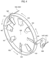
- the first hydraulic cylinder 104 and the second hydraulic cylinder 105 are connected to a link 103 to face each other across a rotation axis 102, and give the link 103 turning forces in the same direction. It should be noted that in Fig.
- 106 denotes a piston of the hydraulic cylinder 104
- 107 denotes a piston of the hydraulic cylinder 105.
- One end of a bell crank 108 is connected to a tip of the piston 106
- one end of a bell crank 109 is connected to a tip of the piston 107.
- Other ends of the bell cranks 108 and 109 are connected to the link 103.
- the bell cranks 108 and 109 are rotatably supported by fixing members (not shown). Accordingly, when the bell cranks 108 and 109 rotate in conjunction with the ejection and retraction of the pistons 106 and 107, the link 103 rotates about the central axis 102. As a result, the angles of rotation of the variable stator vanes 101 are adjusted.
- arrows in Fig. 4 indicate the movement of the bell cranks 108 and 109, the link 103, and the variable stator vanes 101 for the case where the pistons 106 and 107 are displaced in directions (directions of extension) in which the pistons 106 and 107 are pushed out.
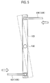
- Fig. 5 shows a modeled link mechanism for the variable stator vanes 101.
- the link 103 is represented as a rod-shaped coaxial synchronous link.
- a central portion of the link 103 is pivotally supported about the rotation axis 102
- the piston 106 of the first hydraulic cylinder 104 is connected to one end of the link 103
- the piston 107 of the second hydraulic cylinder 105 is connected to other end of the link 103 in an opposite direction.
- arrows in Fig. 5 indicate the movement of the link 103 for the case where the pistons 106 and 107 are displaced in directions (directions of extension) in which the pistons 106 and 107 are pushed out.
- Fig. 6 is a block diagram of a conventional actuator control device for controlling the angle of rotation of a modeled synchronous link 2.
- This conventional actuator control device employs a one-servo valve active-standby configuration.
- fluid (working fluid) for driving each hydraulic cylinder is simultaneously supplied to or discharged from the hydraulic cylinders 4 and 5 as actuators through a single servo valve 8.
- Psup denotes supply paths of fluid to the servo valve 8
- Pret denotes return paths of fluid
- Qh denotes flow paths of fluid to respective piston head chambers Ph of the hydraulic cylinders 4 and 5
- Qr denotes flow paths of fluid to respective piston rod chambers Pr of the hydraulic cylinders 4 and 5.
- Displacement sensors F_A and F_B are installed in the pistons 6 and 7 of the hydraulic cylinders 4 and 5, and detect the displacement positions of the pistons 6 and 7 to provide feedback.
- the displacement sensor F_A feeds back a detected displacement value XVSVFB_A indicating the displacement position of the piston 6 of the hydraulic cylinder 4 for driving one end (end A) of the synchronous link 2
- the displacement sensor F_B feeds back a detected displacement value XVSVFB_B indicating the displacement position of the piston 7 of the hydraulic cylinder 5 for driving other end (end B) of the synchronous link 2.
- the single servo valve 8 drives a spool 9 using dual redundant coils T/M_A and T/M_B of a torque motor to perform supply/return operating mode switching and flow rate adjustment. Further, driving currents passed through the dual redundant coils T/M_A and T/M_B of the servo valve 8 are controlled by a control unit 10.
- a servo valve driver 15 receives a control current command from the control unit 10, and performs control so that a torque motor driving current may be passed through one of the dual redundant coils T/M_A and T/M_B which has received the command. This causes the torque motor to rotate by a predetermined angle and causes the spool 9 of the servo valve 8 to move by a predetermined amount of travel.
- the control unit 10 alternately turns on (close) and off (open) current supply switches SW_A and SW_B in order to select a properly operating one of the two systems in the case where a malfunction occurs in one of the two systems, or in order to alternately the activate system A or the system B at every start-up time even when these systems are properly operating.
- a description will be made of feedback control operation for the case where system A is active (ATV) and where system B is standby (STB).
- Control position target values XVSVREF_A and XVSVREF_B (these are generally common values of independent operations) are inputted to plus-signed terminals of subtractors 11 and 12, and the detected displacement values XVSVFB_A and XVSVFB_B of the displacement sensors F_A and F_B are fed back to minus-signed terminals of the subtractors 11 and 12. Further, the subtractors 11 and 12 perform subtractions on these input quantities, and output difference values as controlled variables.
- PID controllers 13 and 14 perform PID operations on the difference values outputted from the subtractors 11 and 12, and output calculation results as current command values.
- the gains of the PID controllers 13 and 14 are K.
- the current command value outputted from the PID controller 13 is inputted to the servo valve driver 15, and the servo valve driver 15 passes a current in accordance with the current command value through the dual redundant coil T/M_A of system A to rotate the torque motor.
- the spool 9 is driven by the rotation of the torque motor to simultaneously supply fluid to the piston head chambers Ph of the two hydraulic cylinders 4 and 5 and simultaneously collect fluid from the piston rod chambers Pr thereof, or to simultaneously supply fluid to the piston rod chambers Pr of the two hydraulic cylinders 4 and 5 and simultaneously collect fluid from the piston head chambers Ph thereof.
- this causes the pistons 6 and 7 of the two hydraulic cylinders 4 and 5 to be pushed out or pulled back by the same amount of displacement, and this produces driving forces which rotate the synchronous link 2 in a forward direction (counterclockwise direction in Fig. 6 ) or in a reverse direction (clockwise direction in Fig. 6 ) by a predetermined angle.
- This is the feedback control of the synchronous link 2 by a conventional actuator control device employing a one-servo valve active-standby configuration.
- a conventional actuator control device employing a one-servo valve active-active configuration has also been known.
- the configuration thereof is shown in Fig. 7 .
- components identical with or similar to those of the conventional actuator control device shown in Fig. 6 are denoted by the same or like reference signs.
- the current supply switches SW_A and SW_B of system A and system B are simultaneously turned on and made active, and a control current is simultaneously passed through the dual redundant coils T/M_A and T/M_B of the torque motor in accordance with results of feedback PID control operations of the PID controllers 13 and 14 to control the servo valve 8.
- both of outputs of the PID controllers 13 and 14 are valid (both are used). Accordingly, the gains of the PID controllers 13 and 14 are set to K/2 in order to obtain the same control performance as that of the configuration of Fig. 6 .
- an actuator control device employing a two-servo valve active-active configuration such as shown in Fig. 8 has also been known. It should be noted that in the actuator control device of Fig. 8 , components identical with or similar to those of the conventional actuator control devices shown in Figs. 6 and 7 are denoted by the same or like reference signs.
- two servo valves 81 and 82 individually drive the two hydraulic cylinders 4 and 5, and turning forces are respectively applied to two opposite ends of the synchronous link 2. These turning forces are simultaneously and individually adjusted in system A and system B by feedback control.
- feedback control in each of system A and system B employs an active-standby configuration. Specifically, when a malfunction occurs in each system, the actuator control device selects a properly operating switch from the current supply switches SW_A1 and SW_A2 of system A, and selects a properly operating switch from the current supply switches SW_B1 and SW_B2 of system B.
- the actuator control device alternately turns on and off the current supply switches SW_A1 and SW_A2 of system A and alternately turns on and off the current supply switches SW_B1 and SW_B2 of system B at every start-up time.
- the gains of the PID controllers 13A and 14A of system A and the PID controllers 13B and 14B of system B are K/2.
- feedback loops for the servo valves 81 and 82 can be formed individually for system A and system B. Accordingly, the lengths of fluid flow paths in system A and system B can be made equal.
- An object of the present invention is to provide an actuator control device which performs the feedback control of the angle of rotation of a synchronous link using two servo valves, which reduces force fighting caused by first and second actuators, and which can accurately control the angle of rotation of the synchronous link.
- An aspect of the present invention is an actuator control device for controlling first and second actuators comprising first and second pistons respectively connected to points of application of forces on a coaxial synchronous link, the points of application being located on opposite sides of a center of rotation of the coaxial synchronous link, the actuator control device comprising: a first servo valve for driving ejection and retraction of the first piston; a second servo valve for driving ejection and retraction of the second piston independently of the first servo valve; displacement sensors for detecting displacement positions of the first and second pistons, respectively; force sensors for measuring forces generated in the first and second actuators, respectively; and a control unit for controlling the first and second servo valves, the control unit configured to: detect the displacement position of the first piston, control the first servo valve by feedback control so that a position of the first piston matches a target position command value, measure both of forces generated in the first and second actuators, correct a target position command value for the second piston in accordance with an amount of imbalance between the forces; and control the second
- the control unit may be configured to measure both of forces generated in the first and second actuators by use of a feedback value of the displacement position of the first piston instead of the target position command value for the second actuator as a target position command value, correct the target position command value for the piston of the second actuator in accordance with an amount of imbalance between the forces, and control the second servo valve in accordance with a difference between the corrected command value and a feedback value of the displacement position of the piston of the second actuator so that the position of the piston of the second actuator matches the corrected command value.
- the displacement of the piston is detected, and the first actuator is controlled by feedback control.
- the second actuator both of forces generated in the first and second actuators are measured, a target position command value is corrected in accordance with an amount of imbalance between the forces, and the second actuator is controlled in accordance with the difference between the corrected command value and a feedback value of the displacement position of the second actuator. Accordingly, force fighting can be avoided, and the angle of rotation of the synchronous link can be accurately controlled.
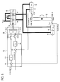
- the actuator control device of the present embodiment employs two-servo valve active-active control.
- the actuator control device includes servo valves 81 and 82 for individually driving hydraulic cylinders 4 and 5 as actuators, and adjusts turning forces applied to two ends of a synchronous link 2 by feedback control simultaneously and individually in system A and system B.
- the actuator control device employs an active-standby configuration. Accordingly, in the case where a malfunction occurs in system A, the actuator control device selects a properly operating switch between current supply switches SW_A1 and SW_A2 of system A.
- the actuator control device selects a properly operating switch between the current supply switches SW_B1 and SW_B2 of system B. Moreover, even in the case where no malfunction occurs, the actuator control device alternately turns on and off the current supply switches SW_A1 and SW_A2 and alternately turns on and off the current supply switches SW_B1 and SW_B2 in system A and system B at every start-up time.
- the gains of PID controllers 13A and 14A of system A and PID controllers 13B and 14B of system B are K/2. It should be noted that in Fig. 1 , components identical with or similar to those of the actuator control device of Fig. 8 are denoted by the same or like reference signs.
- the feedback control of system B in the present embodiment is the same as that of the conventional example shown in Fig. 8 .
- system A in the present embodiment a control command value is corrected in accordance with the amount of imbalance between forces of the hydraulic cylinders 4 and 5, and feedback control is performed using the corrected control command value as in system B.
- the hydraulic cylinder 5 of system B corresponds to a first actuator
- the hydraulic cylinder 4 of system A corresponds to a second actuator.
- a pressure sensor 21A is installed in a piston head chamber Ph of the hydraulic cylinder 4, and a pressure sensor 22A is installed in a piston rod chamber Pr thereof.
- a pressure sensor 21B is installed in a piston head chamber Ph of the hydraulic cylinder 5, and a pressure sensor 22B is installed in a piston rod chamber Pr thereof.
- a pressure sensor may be a differential pressure sensor for measuring the difference between the piston head chamber Ph and the piston rod chamber Pr of each hydraulic piston cylinder.
- the actuator control device of the present embodiment includes force calculators 23 and 24.
- the force calculator 23 calculates a force (Pha*Ah-Pra*Ar) acting on a piston head of the hydraulic cylinder 4 of system A.
- the force calculator 24 calculates a force (Phb*Ah-Prb*Ar) acting on a piston head of the hydraulic cylinder 5 of system B.
- a subtractor 25 receives calculation results from the force calculators 23 and 24, and subtracts the force of system B from the force of system A to output the amount of force imbalance ⁇ FP.
- the amount of force imbalance ⁇ FP is attenuated by an attenuator 26, integrated with respect to time by an integrator 27 to be converted to a unit of distance, and then fed back to minus-signed terminals of subtractors 28 and 29 newly disposed in a feedback loop of system A as a correction value ⁇ Ft of the amount of force imbalance.
- Each of the plus-signed terminals of the subtractors 28 and 29 receives a control position target value XVSVREF_A for a servo valve 81. Accordingly, outputs of the subtractors 28 and 29 are values calculated from (control position target value XVSVREF_A-correction quantity ⁇ Ft), and are passed to plus-signed terminals of feedback subtractors 11A and 12A of system A.
- Detected displacement values XVSVFB_A and XVSVFB_B indicating piston displacement positions detected by displacement sensors F_A and F_B are fed back to minus-signed terminals of the subtractors 11A and 12A of system A and minus-signed terminals of subtractors 11B and 12B of system B.
- control position target values XVSVREF_A and XVSVREF_B are externally inputted to system A and system B, respectively.
- System B controls the hydraulic cylinder 5 as a first actuator.
- the displacement sensor F_B detects the position displacement of the piston (first piston) of the hydraulic cylinder 5, and outputs a detected displacement value XVSVFB_B to provide feedback to the subtractors 11B and 12B of a control unit 10B.
- the subtractors 11B and 12B subtract the detected displacement value XVSVFB_B as a feedback value from the control position target value XVSVREF_B, and input the difference value ⁇ SV_B to the PID controllers 13B and 14B.
- the PID controllers 13B and 14B perform PID control operations on the inputted difference value ⁇ SV_B, and output a current manipulated variable ⁇ SVI_B. Since the current supply switch SW_B1 of the current supply switches SW_B1 and SW_B2 is on, the current manipulated variable ⁇ SVI_B is inputted to the servo valve driver 15B through the current supply switch SW_B1 hereafter.
- the servo valve driver 15B Upon receiving the current manipulated variable, the servo valve driver 15B passes a current of the current manipulated variable ⁇ SVI_B through the dual redundant coils T/M_B1 to rotate a torque motor in a predetermined direction in accordance with the current by a predetermined angle.
- This causes a spool 92 to move by a predetermined amount, causes fluid to be supplied to the piston head chamber Ph of the hydraulic cylinder 5 by a predetermined amount in accordance with the amount of travel of the spool 92 or causes fluid to be supplied to the piston rod chamber Pr by a predetermined amount in accordance with the amount of travel of the spool 92, and causes the piston 7 in a forward or reverse direction by a required amount.
- control is performed so that the position of the piston 7 may match the control position target value (target position command value) XVSVREF_B. Further, this control is repeated with a control period.
- This control causes one end (end B) of the synchronous link 2 connected to the piston 7 to be pushed out or pulled back and rotate to a predetermined angle.
- System A controls the hydraulic cylinder 4 as a second actuator.
- position-based force correction control is performed.
- the pressure sensor 21A detects the pressure in the piston head chamber Ph of the hydraulic cylinder 4, and outputs the detected pressure value Pha to the force calculator 23.
- the pressure sensor 22A detects the pressure in the piston rod chamber Pr, and outputs the detected pressure value Pra to the force calculator 23.
- the force calculator 23 calculates the pressure difference between the piston head chamber Ph and the piston rod chamber Pr, and outputs the pressure difference to the plus-signed terminal of the subtractor 25.
- the pressure difference is obtained from the expression (Pha*Ah-Pra*Ar), where Ah is the cross-sectional area of the piston head chamber Ph, and Ar is the cross-sectional area of the piston rod chamber Pr.
- the pressure difference between the piston head chamber Ph and the piston rod chamber Pr is obtained as in system A.
- the pressure sensor 21B detects the pressure in the piston head chamber Ph of the hydraulic cylinder 5, and outputs the detected pressure value Phb to the force calculator 24.
- the pressure sensor 22B detects the pressure in the piston rod chamber Pr, and outputs the detected pressure value Prb to the force calculator 24.
- the force calculator 24 calculates the pressure difference between the piston head chamber Ph and the piston rod chamber Pr, and outputs the pressure difference to a minus-signed terminal of the subtractor 25.
- the pressure difference is obtained from the expression (Phb*Ah-Prb*Ar), where Ah is the cross-sectional area of the piston head chamber Ph, and Ar is the cross-sectional area of the piston rod chamber Pr. It should be noted that since the two hydraulic cylinders 4 and 5 are built to the same specifications, the cross-sectional areas Ah and Ar have the same value.
- the piston head of the piston 6 in the hydraulic cylinder 4 is subject to a force.
- the piston head of the piston 7 in the hydraulic cylinder 5 is subject to a force.
- the subtractor 25 of a control unit 10A calculates and outputs the amount of imbalance ⁇ FP as a deviation of these forces.
- the attenuator 26 attenuates the amount of imbalance ⁇ FP.
- the integrator 27 integrates the amount of imbalance ⁇ FP attenuated by the attenuator 26 with respect to time, and outputs a correction value ⁇ Ft.
- the time integration by the integrator 27 is performed for conversion to a unit of distance by force ⁇ time.
- the correction value ⁇ Ft outputted from the integrator 27 is inputted to the minus-signed terminals of the subtractors 28 and 29.
- the subtractors 28 and 29 subtract the correction value ⁇ Ft of the amount of force imbalance ⁇ FP from the control position target value (target position command value) XVSVREF_A, and output the corrected control position target value (corrected target position command value) XVSVREF_A' obtained by the subtraction to the subtractors 11A and 12A. Similar to the feedback control in system B, the subtractors 11A and 12A subtract a detected displacement value XVSVFB_A of the displacement sensor F_A as a feedback value from the corrected control position target value XVSVREF_A', and input the difference value ⁇ SV_A obtained by the subtraction to the PID controllers 13A and 14A.
- the PID controllers 13A and 14A perform PID control operations on the inputted difference value ⁇ SV_A, and output the current manipulated variable ⁇ SVI_A.
- the current manipulated variable ⁇ SVI_A is inputted to the servo valve driver 15A through the current supply switch SW_A1.
- the servo valve driver 15A Upon receiving the current manipulated variable ⁇ SVI_A, the servo valve driver 15A passes a current corresponding to the current manipulated variable ⁇ SVI_A through the dual redundant coil T/M_A1 to rotate a torque motor in a forward or reverse direction by a predetermined angle. This causes a spool 91 to move by a predetermined amount, causes fluid to be supplied to the piston head chamber Ph or the piston rod chamber Pr of the hydraulic cylinder 4 by a predetermined amount in accordance with the amount of travel of the spool 91, and causes the piston 6 to move in a forward or reverse direction by a required amount.
- control is performed so that the position of the piston 6 may match the control position target value XVSVREF_A' corrected with the amount of force imbalance ⁇ FP. Further, this control is repeated with a control period.
- This control causes other end (end A) of the synchronous link 2 connected to the piston 6 to be pushed out or pulled back and rotate to a predetermined angle.
- the actuator control device employs an active-standby configuration in which the current supply switches SW_A1 and SW_A2 of system A and the current supply switches SW_B1 and SW_B2 of system B are alternately turned on/off (switch to be used is switched) every time a malfunction in one system (system including a current supply switch) or start-up occurs.
- the actuator control device may also employ an active-active configuration instead of the foregoing configuration in each of system A and system B as shown in Fig. 7 . In that case, the gains of the PID controllers 13A, 13B, 14A, and 14B are set to K/4.
- PI control with high control performance may also be employed.
- a force correction controller including the attenuator 26 and the integrator 27 may also employ P control with fast responsiveness instead of I control.
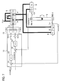
- Fig. 2 shows an actuator control device of a second embodiment.
- values given to the plus-signed terminals of the subtractors 28 and 29 are the control position target value XVSVREF_A externally supplied as a control command value for system A for controlling the hydraulic cylinder 4 corresponding to a second actuator.
- the detected displacement value XVSVFB_B of the displacement sensor F_B of system B for controlling the hydraulic cylinder 5 corresponding to a first actuator is given to the plus-signed terminals of the subtractors 28 and 29.
- the configuration of the second embodiment is the same as that of the first embodiment.
- the actuator control device of the present embodiment operates as follows. This explanation assumes a situation in which a malfunction occurs in one system of system A and system B or a situation in which the actuator control device is started up. Specifically, the following is assumed: in system A, the current supply switch SW_A1 is on, and the current supply switch SW_A2 is off; and, in system B, the current supply switch SW_B1 is on, and the current supply switch SW_B2 is off.
- control position target value XVSVREF_B is externally inputted to the plus-signed terminals of the subtractors 11B and 12B.
- the detected displacement value XVSVFB_B of the displacement sensor F_B which is a feedback value from system B, is inputted to the plus-signed terminals of the subtractors 28 and 29 as a control position target value.
- Control in system B is similar to the feedback control in system B of the first embodiment shown in Fig. 1 .
- This control causes one end (end B) of the synchronous link 2 connected to the piston 7 to be pushed out or pulled back and rotate to a predetermined angle.
- position-based force correction control is performed on the feedback value from system B.
- a correction value ⁇ Ft for force imbalance inputted to the minus-signed terminals of the subtractors 28 and 29 is calculated as in the first embodiment.
- the subtractors 28 and 29 subtract the correction value ⁇ Ft for the amount of force imbalance from the detected displacement value XVSVFB_B, and output the corrected detected displacement value XVSVFB_B' to the subtractors 11A and 12A. Similar to the feedback control in system B, these subtractors 11A and 12A subtract the detected displacement value XVSVFB_A of the displacement sensor F_A as a feedback value from the corrected detected displacement value XVSVFB_B', and input the difference value ⁇ SV_A to the PID controllers 13A and 14A. The PID controllers 13A and 14A perform PID control operations based on the inputted difference value ⁇ SV_A, and output a current manipulated variable ⁇ SVI_A. Since SW_A1 of the current supply switches SW_A1 and SW_A2 is on, the current manipulated variable ⁇ SVI_A is inputted to the servo valve driver 15A through the current supply switch SW_A1.
- the servo valve driver 15A Upon receiving the current manipulated variable ⁇ SVI_A, the servo valve driver 15A passes a current of the current manipulated variable ⁇ SVI_A through the dual redundant coils T/M_A1 to rotate a torque motor in a forward or reverse direction by a predetermined angle. This causes the spool 91 to move by a predetermined amount, causes fluid to be supplied to the piston head chamber Ph or the piston rod chamber Pr of the hydraulic cylinder 4 by a predetermined amount in accordance with the amount of travel of the spool 91, and causes the piston 6 to move in a forward or reverse direction by a required amount.
- control is performed so that the position of the piston 6 may match the control position target value XVSVREF_A' corrected with the amount of force imbalance ⁇ FP. Further, this control is repeated with a control period.
- This control causes other end (end A) of the synchronous link 2 connected to the piston 6 to be pushed out or pulled back and rotate to a predetermined angle.
- imbalance between pushing or pulling forces of the pistons 6 and 7 in the hydraulic cylinders 4 and 5 is absorbed in advance by feedback control in system A as in the first embodiment. Accordingly, though the hydraulic cylinders 4 and 5 are individually controlled in system A and system B, force imbalance between the two is not created. As a result, forces acting on two opposite ends of the synchronous link 2 match, and the angle of rotation of the synchronous link 2 can be controlled in a state in which force fighting does not occur. Moreover, since the detected displacement value XVSVFB_B of system B is used as a control target value of system A, the amount of force imbalance can be corrected, and feedback control can be performed based on the difference between feedback values of system A and system B. As a result, compared to the first embodiment, forces acting on two opposite ends of the synchronous link 2 and the amounts of travel thereof can be matched better, and force fighting can be more effectively reduced.
- the actuator control device employs an active-standby configuration in which the current supply switches SW_A1 and SW_A2 of system A and the current supply switches SW_B1 and SW_B2 of system B are alternately turned on/off at every start-up time (switch to be used is switched), but may be employ an active-active configuration in each of system A and system B as shown in Fig. 7 instead.
- the gains of the PID controllers 13A, 13B, 14A, and 14B are set to K/4.
- PI control with high control performance may also be employed.
- a force correction controller including the attenuator 26 and the integrator 27 may also employ P control with fast responsiveness instead of I control.
- Fig. 3 (a) shows response characteristics of a conventional actuator control device employing a two-servo valve active-active configuration shown in Fig. 8 .
- Fig. 3 (b) shows response characteristics of an actuator control device employing two-servo valve active-active position-based force control of the second embodiment shown in Fig. 2 .
- curve A represents the angle of rotation of the synchronous link 2 in system A
- curve B represents the angle of rotation of the synchronous link 2 in system B
- the overlap between the two curves indicates that the positions of the two actuators coincide.
- the conventional example since there is a difference between the angles of rotation in system A and system B, a deflection occurs in the synchronous link 2.
- angles by which system A and system B attempt to perform rotation approximately match. Accordingly, forces acting from the hydraulic cylinders 4 and 5 on the synchronous link 2 are similar, and it can be understood that there occurs little force fighting.
- a strain gauge may be provided in an actuator as a force sensor.
Landscapes
- Engineering & Computer Science (AREA)
- Physics & Mathematics (AREA)
- Fluid Mechanics (AREA)
- Chemical & Material Sciences (AREA)
- Combustion & Propulsion (AREA)
- Mechanical Engineering (AREA)
- General Engineering & Computer Science (AREA)
- Servomotors (AREA)
Abstract
Description
- The present invention relates to an actuator control device for a dual-control actuator which adjusts the angles of variable stator vanes used in a fan, a compressor, a turbine, or the like of a jet engine.
- A fan, a compressor, or a turbine of a jet engine is provided with
variable stator vanes 101. As shown inFig. 4 , thevariable stator vanes 101 are configured such that the angles thereof can be changed in accordance with load status. To change the angles of thevariable stator vanes 101, a first (master-side)hydraulic cylinder 104 as a first actuator and a second (slave-side)hydraulic cylinder 105 as a second actuator are used. The firsthydraulic cylinder 104 and the secondhydraulic cylinder 105 are connected to alink 103 to face each other across arotation axis 102, and give thelink 103 turning forces in the same direction. It should be noted that inFig. 4 , 106 denotes a piston of thehydraulic cylinder hydraulic cylinder 105. One end of abell crank 108 is connected to a tip of thepiston 106, and one end of abell crank 109 is connected to a tip of thepiston 107. Other ends of thebell cranks link 103. Thebell cranks bell cranks pistons link 103 rotates about thecentral axis 102. As a result, the angles of rotation of thevariable stator vanes 101 are adjusted. It should be noted that arrows inFig. 4 indicate the movement of thebell cranks link 103, and the variable stator vanes 101 for the case where thepistons pistons -
Fig. 5 shows a modeled link mechanism for thevariable stator vanes 101. By modeling, thelink 103 is represented as a rod-shaped coaxial synchronous link. In this model, a central portion of thelink 103 is pivotally supported about therotation axis 102, thepiston 106 of the firsthydraulic cylinder 104 is connected to one end of thelink 103, and thepiston 107 of the secondhydraulic cylinder 105 is connected to other end of thelink 103 in an opposite direction. When thepistons link 103. It should be noted that arrows inFig. 5 indicate the movement of thelink 103 for the case where thepistons pistons -
Fig. 6 is a block diagram of a conventional actuator control device for controlling the angle of rotation of a modeledsynchronous link 2. This conventional actuator control device employs a one-servo valve active-standby configuration. In this configuration, fluid (working fluid) for driving each hydraulic cylinder is simultaneously supplied to or discharged from thehydraulic cylinders single servo valve 8. Psup denotes supply paths of fluid to theservo valve 8, Pret denotes return paths of fluid, Qh denotes flow paths of fluid to respective piston head chambers Ph of thehydraulic cylinders hydraulic cylinders pistons hydraulic cylinders pistons Fig. 6 , the displacement sensor F_A feeds back a detected displacement value XVSVFB_A indicating the displacement position of thepiston 6 of thehydraulic cylinder 4 for driving one end (end A) of thesynchronous link 2, and the displacement sensor F_B feeds back a detected displacement value XVSVFB_B indicating the displacement position of thepiston 7 of thehydraulic cylinder 5 for driving other end (end B) of thesynchronous link 2. - Moreover, in the actuator control device of
Fig. 6 , thesingle servo valve 8 drives aspool 9 using dual redundant coils T/M_A and T/M_B of a torque motor to perform supply/return operating mode switching and flow rate adjustment. Further, driving currents passed through the dual redundant coils T/M_A and T/M_B of theservo valve 8 are controlled by acontrol unit 10. Aservo valve driver 15 receives a control current command from thecontrol unit 10, and performs control so that a torque motor driving current may be passed through one of the dual redundant coils T/M_A and T/M_B which has received the command. This causes the torque motor to rotate by a predetermined angle and causes thespool 9 of theservo valve 8 to move by a predetermined amount of travel. - The
control unit 10 alternately turns on (close) and off (open) current supply switches SW_A and SW_B in order to select a properly operating one of the two systems in the case where a malfunction occurs in one of the two systems, or in order to alternately the activate system A or the system B at every start-up time even when these systems are properly operating. In the following, for convenience of explanation, a description will be made of feedback control operation for the case where system A is active (ATV) and where system B is standby (STB). Control position target values XVSVREF_A and XVSVREF_B (these are generally common values of independent operations) are inputted to plus-signed terminals ofsubtractors subtractors subtractors PID controllers subtractors PID controllers - As shown in
Fig. 6 , when system A and system B are respectively set to active and standby, and the current supply switch SW_A and the current supply switch SW_B are respectively on and off, the current command value outputted from thePID controller 13 is inputted to theservo valve driver 15, and theservo valve driver 15 passes a current in accordance with the current command value through the dual redundant coil T/M_A of system A to rotate the torque motor. Thespool 9 is driven by the rotation of the torque motor to simultaneously supply fluid to the piston head chambers Ph of the twohydraulic cylinders hydraulic cylinders pistons hydraulic cylinders synchronous link 2 in a forward direction (counterclockwise direction inFig. 6 ) or in a reverse direction (clockwise direction inFig. 6 ) by a predetermined angle. This is the feedback control of thesynchronous link 2 by a conventional actuator control device employing a one-servo valve active-standby configuration. - Moreover, a conventional actuator control device employing a one-servo valve active-active configuration has also been known. The configuration thereof is shown in
Fig. 7 . In the actuator control device ofFig. 7 , components identical with or similar to those of the conventional actuator control device shown inFig. 6 are denoted by the same or like reference signs. - In the conventional actuator control device shown in
Fig. 7 , in thecontrol unit 10, the current supply switches SW_A and SW_B of system A and system B are simultaneously turned on and made active, and a control current is simultaneously passed through the dual redundant coils T/M_A and T/M_B of the torque motor in accordance with results of feedback PID control operations of thePID controllers servo valve 8. In this configuration, both of outputs of thePID controllers PID controllers Fig. 6 . - These conventional actuator control devices perform the operation of simultaneously supplying or collecting fluid to/from the piston head chambers Ph and the piston rod chambers Pr through the
single servo valve 8 and the flow paths Qh and Qr. It is impossible to perform control so that thepistons hydraulic cylinders hydraulic cylinders single servo valve 8 to thehydraulic cylinders synchronous link 2 and junctions. Accordingly, turning forces acting on two opposite ends of thesynchronous link 2 do not strictly match, and may create an imbalance. In that case, there has been a problem that so-called force fighting occurs which applies an excessive force to thesynchronous link 2. - As an actuator control device which solves this, an actuator control device employing a two-servo valve active-active configuration such as shown in
Fig. 8 has also been known. It should be noted that in the actuator control device ofFig. 8 , components identical with or similar to those of the conventional actuator control devices shown inFigs. 6 and7 are denoted by the same or like reference signs. - In this configuration shown in
Fig. 8 , twoservo valves hydraulic cylinders synchronous link 2. These turning forces are simultaneously and individually adjusted in system A and system B by feedback control. Moreover, feedback control in each of system A and system B employs an active-standby configuration. Specifically, when a malfunction occurs in each system, the actuator control device selects a properly operating switch from the current supply switches SW_A1 and SW_A2 of system A, and selects a properly operating switch from the current supply switches SW_B1 and SW_B2 of system B. Moreover, even in a normal case, the actuator control device alternately turns on and off the current supply switches SW_A1 and SW_A2 of system A and alternately turns on and off the current supply switches SW_B1 and SW_B2 of system B at every start-up time. It should be noted that the gains of thePID controllers PID controllers - In the case of the conventional example of this type, feedback loops for the
servo valves synchronous link 2 is not sufficiently eliminated. -
- [PTL1]
Japanese Patent Application Publication No. 2011-127639 - [PTL 2]
Japanese Patent No. 4209037 - [PTL 3]
Japanese Patent No. 3994208 - [PTL 4]
Japanese Patent Application Publication No. 2008-090692 - [PTL 5] International Publication No.
WO07/141839 - An object of the present invention is to provide an actuator control device which performs the feedback control of the angle of rotation of a synchronous link using two servo valves, which reduces force fighting caused by first and second actuators, and which can accurately control the angle of rotation of the synchronous link.
- An aspect of the present invention is an actuator control device for controlling first and second actuators comprising first and second pistons respectively connected to points of application of forces on a coaxial synchronous link, the points of application being located on opposite sides of a center of rotation of the coaxial synchronous link, the actuator control device comprising: a first servo valve for driving ejection and retraction of the first piston; a second servo valve for driving ejection and retraction of the second piston independently of the first servo valve; displacement sensors for detecting displacement positions of the first and second pistons, respectively; force sensors for measuring forces generated in the first and second actuators, respectively; and a control unit for controlling the first and second servo valves, the control unit configured to: detect the displacement position of the first piston, control the first servo valve by feedback control so that a position of the first piston matches a target position command value, measure both of forces generated in the first and second actuators, correct a target position command value for the second piston in accordance with an amount of imbalance between the forces; and control the second servo valve in accordance with a difference between the corrected command value and a feedback value of the displacement position of the second piston so that a position of the second piston matches the corrected command value.
- The control unit may be configured to measure both of forces generated in the first and second actuators by use of a feedback value of the displacement position of the first piston instead of the target position command value for the second actuator as a target position command value, correct the target position command value for the piston of the second actuator in accordance with an amount of imbalance between the forces, and control the second servo valve in accordance with a difference between the corrected command value and a feedback value of the displacement position of the piston of the second actuator so that the position of the piston of the second actuator matches the corrected command value.
- In the actuator control device of the present invention, for the first actuator, the displacement of the piston is detected, and the first actuator is controlled by feedback control. For the second actuator, both of forces generated in the first and second actuators are measured, a target position command value is corrected in accordance with an amount of imbalance between the forces, and the second actuator is controlled in accordance with the difference between the corrected command value and a feedback value of the displacement position of the second actuator. Accordingly, force fighting can be avoided, and the angle of rotation of the synchronous link can be accurately controlled.
- Moreover, in the control of the second actuator, by using a feedback value of the displacement position of the first actuator as a target position command value, correcting the command value in accordance with the amount of imbalance between forces generated in the first and second actuators, and controlling the second actuator in accordance with the difference between the corrected command value and the feedback value of the displacement position of the second actuator, force fighting can be avoided, and the angle of rotation of the synchronous link can be accurately controlled.
-
- [
Fig. 1 ]
Fig. 1 is a control block diagram of an actuator control device of a first embodiment of the present invention. - [
Fig. 2 ]
Fig. 2 is a control block diagram of an actuator control device of a second embodiment of the present invention. - [
Fig. 3 ]
Fig. 3 (a) is a graph showing control characteristics of an actuator control device of a conventional example, andFig. 3 (b) is a graph showing control characteristics of the actuator control device of the above-described second embodiment. - [
Fig. 4 ]
Fig. 4 is a view for explaining a mechanism for driving variable stator vanes of a fan of a jet engine. - [
Fig. 5 ]
Fig. 5 is an explanatory diagram of a modeled mechanism for driving the above-described variable stator vanes. - [
Fig. 6 ]
Fig. 6 is a control block diagram of a conventional actuator control device employing a one-servo valve active-standby configuration. - [
Fig. 7 ]
Fig. 7 is a control block diagram of a conventional actuator control device employing a one-servo valve active-active configuration. - [
Fig. 8 ]
Fig. 8 is a control block diagram of a conventional actuator control device employing a two-servo valve active-active configuration. - Hereinafter, embodiments of the present invention will be described in detail with reference to drawings.
- An actuator control device of a first embodiment shown in
Fig. 1 will be described. The actuator control device of the present embodiment employs two-servo valve active-active control. The actuator control device includesservo valves hydraulic cylinders synchronous link 2 by feedback control simultaneously and individually in system A and system B. Moreover, with regard to the feedback control in each of system A and system B, the actuator control device employs an active-standby configuration. Accordingly, in the case where a malfunction occurs in system A, the actuator control device selects a properly operating switch between current supply switches SW_A1 and SW_A2 of system A. Alternatively, in the case where a malfunction occurs in system B, the actuator control device selects a properly operating switch between the current supply switches SW_B1 and SW_B2 of system B. Moreover, even in the case where no malfunction occurs, the actuator control device alternately turns on and off the current supply switches SW_A1 and SW_A2 and alternately turns on and off the current supply switches SW_B1 and SW_B2 in system A and system B at every start-up time. The gains ofPID controllers PID controllers Fig. 1 , components identical with or similar to those of the actuator control device ofFig. 8 are denoted by the same or like reference signs. - The feedback control of system B in the present embodiment is the same as that of the conventional example shown in
Fig. 8 . Meanwhile, in system A in the present embodiment, a control command value is corrected in accordance with the amount of imbalance between forces of thehydraulic cylinders hydraulic cylinder 5 of system B corresponds to a first actuator, and thehydraulic cylinder 4 of system A corresponds to a second actuator. - In the actuator control device of the present embodiment, in order to calculate a correction value in accordance with the amount of force imbalance in system A, a
pressure sensor 21A is installed in a piston head chamber Ph of thehydraulic cylinder 4, and apressure sensor 22A is installed in a piston rod chamber Pr thereof. Moreover, apressure sensor 21B is installed in a piston head chamber Ph of thehydraulic cylinder 5, and apressure sensor 22B is installed in a piston rod chamber Pr thereof. It should be noted that a pressure sensor may be a differential pressure sensor for measuring the difference between the piston head chamber Ph and the piston rod chamber Pr of each hydraulic piston cylinder. - The actuator control device of the present embodiment includes
force calculators force calculator 23 calculates a force (Pha*Ah-Pra*Ar) acting on a piston head of thehydraulic cylinder 4 of system A. Theforce calculator 24 calculates a force (Phb*Ah-Prb*Ar) acting on a piston head of thehydraulic cylinder 5 of system B. A subtractor 25 receives calculation results from theforce calculators attenuator 26, integrated with respect to time by anintegrator 27 to be converted to a unit of distance, and then fed back to minus-signed terminals ofsubtractors subtractors servo valve 81. Accordingly, outputs of thesubtractors feedback subtractors subtractors subtractors - Next, an operation for controlling the
servo valves synchronous link 2 by the actuator control device having the above-described configuration will be described. In this description, the following is assumed: at the time of start-up, in system A, the current supply switch SW_A1 is on, and the current supply switch SW_A2 is off; and, in system B, the current supply switch SW_B1 is on, and the current supply switch SW_B2 is off. It should be noted that at the time of next start-up, the on and off of the switches are inversed. Moreover, this feedback control loop is repeated with a predetermined short period on the order of µsec or msec. Accordingly, time integration by theintegrator 27 is equal to this control period. - In the state shown in
Fig. 1 , control position target values XVSVREF_A and XVSVREF_B are externally inputted to system A and system B, respectively. - First, control in system B will be described. System B controls the
hydraulic cylinder 5 as a first actuator. The displacement sensor F_B detects the position displacement of the piston (first piston) of thehydraulic cylinder 5, and outputs a detected displacement value XVSVFB_B to provide feedback to thesubtractors control unit 10B. Thesubtractors PID controllers PID controllers servo valve driver 15B through the current supply switch SW_B1 hereafter. - Upon receiving the current manipulated variable, the
servo valve driver 15B passes a current of the current manipulated variable ΔSVI_B through the dual redundant coils T/M_B1 to rotate a torque motor in a predetermined direction in accordance with the current by a predetermined angle. This causes aspool 92 to move by a predetermined amount, causes fluid to be supplied to the piston head chamber Ph of thehydraulic cylinder 5 by a predetermined amount in accordance with the amount of travel of thespool 92 or causes fluid to be supplied to the piston rod chamber Pr by a predetermined amount in accordance with the amount of travel of thespool 92, and causes thepiston 7 in a forward or reverse direction by a required amount. In other words, control is performed so that the position of thepiston 7 may match the control position target value (target position command value) XVSVREF_B. Further, this control is repeated with a control period. This control causes one end (end B) of thesynchronous link 2 connected to thepiston 7 to be pushed out or pulled back and rotate to a predetermined angle. - Next, control in system A will be described. System A controls the
hydraulic cylinder 4 as a second actuator. In system A, position-based force correction control is performed. Thepressure sensor 21A detects the pressure in the piston head chamber Ph of thehydraulic cylinder 4, and outputs the detected pressure value Pha to theforce calculator 23. Thepressure sensor 22A detects the pressure in the piston rod chamber Pr, and outputs the detected pressure value Pra to theforce calculator 23. Theforce calculator 23 calculates the pressure difference between the piston head chamber Ph and the piston rod chamber Pr, and outputs the pressure difference to the plus-signed terminal of thesubtractor 25. The pressure difference is obtained from the expression (Pha*Ah-Pra*Ar), where Ah is the cross-sectional area of the piston head chamber Ph, and Ar is the cross-sectional area of the piston rod chamber Pr. - In system B, again, the pressure difference between the piston head chamber Ph and the piston rod chamber Pr is obtained as in system A. The
pressure sensor 21B detects the pressure in the piston head chamber Ph of thehydraulic cylinder 5, and outputs the detected pressure value Phb to theforce calculator 24. Thepressure sensor 22B detects the pressure in the piston rod chamber Pr, and outputs the detected pressure value Prb to theforce calculator 24. Theforce calculator 24 calculates the pressure difference between the piston head chamber Ph and the piston rod chamber Pr, and outputs the pressure difference to a minus-signed terminal of thesubtractor 25. The pressure difference is obtained from the expression (Phb*Ah-Prb*Ar), where Ah is the cross-sectional area of the piston head chamber Ph, and Ar is the cross-sectional area of the piston rod chamber Pr. It should be noted that since the twohydraulic cylinders - The piston head of the
piston 6 in thehydraulic cylinder 4 is subject to a force. Similarly, the piston head of thepiston 7 in thehydraulic cylinder 5 is subject to a force. Thesubtractor 25 of acontrol unit 10A calculates and outputs the amount of imbalance ΔFP as a deviation of these forces. Theattenuator 26 attenuates the amount of imbalance ΔFP. Then, theintegrator 27 integrates the amount of imbalance ΔFP attenuated by theattenuator 26 with respect to time, and outputs a correction value ΔFt. The time integration by theintegrator 27 is performed for conversion to a unit of distance by force×time. The correction value ΔFt outputted from theintegrator 27 is inputted to the minus-signed terminals of thesubtractors - The
subtractors subtractors subtractors PID controllers PID controllers servo valve driver 15A through the current supply switch SW_A1. - Upon receiving the current manipulated variable ΔSVI_A, the
servo valve driver 15A passes a current corresponding to the current manipulated variable ΔSVI_A through the dual redundant coil T/M_A1 to rotate a torque motor in a forward or reverse direction by a predetermined angle. This causes aspool 91 to move by a predetermined amount, causes fluid to be supplied to the piston head chamber Ph or the piston rod chamber Pr of thehydraulic cylinder 4 by a predetermined amount in accordance with the amount of travel of thespool 91, and causes thepiston 6 to move in a forward or reverse direction by a required amount. In other words, control is performed so that the position of thepiston 6 may match the control position target value XVSVREF_A' corrected with the amount of force imbalance ΔFP. Further, this control is repeated with a control period. This control causes other end (end A) of thesynchronous link 2 connected to thepiston 6 to be pushed out or pulled back and rotate to a predetermined angle. - In the case of the present embodiment, imbalance between pushing or pulling forces of the
pistons hydraulic cylinders hydraulic cylinders synchronous link 2 match, and the angle of rotation of thesynchronous link 2 can be controlled in a state in which force fighting does not occur. - It should be noted that the actuator control device according to this first embodiment employs an active-standby configuration in which the current supply switches SW_A1 and SW_A2 of system A and the current supply switches SW_B1 and SW_B2 of system B are alternately turned on/off (switch to be used is switched) every time a malfunction in one system (system including a current supply switch) or start-up occurs. However, the actuator control device may also employ an active-active configuration instead of the foregoing configuration in each of system A and system B as shown in
Fig. 7 . In that case, the gains of thePID controllers PID controllers attenuator 26 and theintegrator 27 may also employ P control with fast responsiveness instead of I control. -
Fig. 2 shows an actuator control device of a second embodiment. In the first embodiment shown inFig. 1 , values given to the plus-signed terminals of thesubtractors hydraulic cylinder 4 corresponding to a second actuator. In the second embodiment, instead of the control position target value XVSVREF_A, the detected displacement value XVSVFB_B of the displacement sensor F_B of system B for controlling thehydraulic cylinder 5 corresponding to a first actuator is given to the plus-signed terminals of thesubtractors - The actuator control device of the present embodiment operates as follows. This explanation assumes a situation in which a malfunction occurs in one system of system A and system B or a situation in which the actuator control device is started up. Specifically, the following is assumed: in system A, the current supply switch SW_A1 is on, and the current supply switch SW_A2 is off; and, in system B, the current supply switch SW_B1 is on, and the current supply switch SW_B2 is off.
- In the state shown in
Fig. 2 , in system B, the control position target value XVSVREF_B is externally inputted to the plus-signed terminals of thesubtractors subtractors - Control in system B is similar to the feedback control in system B of the first embodiment shown in
Fig. 1 . This control causes one end (end B) of thesynchronous link 2 connected to thepiston 7 to be pushed out or pulled back and rotate to a predetermined angle. - In system A, position-based force correction control is performed on the feedback value from system B. A correction value ΔFt for force imbalance inputted to the minus-signed terminals of the
subtractors - The
subtractors subtractors subtractors PID controllers PID controllers servo valve driver 15A through the current supply switch SW_A1. - Upon receiving the current manipulated variable ΔSVI_A, the
servo valve driver 15A passes a current of the current manipulated variable ΔSVI_A through the dual redundant coils T/M_A1 to rotate a torque motor in a forward or reverse direction by a predetermined angle. This causes thespool 91 to move by a predetermined amount, causes fluid to be supplied to the piston head chamber Ph or the piston rod chamber Pr of thehydraulic cylinder 4 by a predetermined amount in accordance with the amount of travel of thespool 91, and causes thepiston 6 to move in a forward or reverse direction by a required amount. In other words, control is performed so that the position of thepiston 6 may match the control position target value XVSVREF_A' corrected with the amount of force imbalance ΔFP. Further, this control is repeated with a control period. This control causes other end (end A) of thesynchronous link 2 connected to thepiston 6 to be pushed out or pulled back and rotate to a predetermined angle. - In the present embodiment, imbalance between pushing or pulling forces of the
pistons hydraulic cylinders hydraulic cylinders synchronous link 2 match, and the angle of rotation of thesynchronous link 2 can be controlled in a state in which force fighting does not occur. Moreover, since the detected displacement value XVSVFB_B of system B is used as a control target value of system A, the amount of force imbalance can be corrected, and feedback control can be performed based on the difference between feedback values of system A and system B. As a result, compared to the first embodiment, forces acting on two opposite ends of thesynchronous link 2 and the amounts of travel thereof can be matched better, and force fighting can be more effectively reduced. - It should be noted that the actuator control device according to this second embodiment employs an active-standby configuration in which the current supply switches SW_A1 and SW_A2 of system A and the current supply switches SW_B1 and SW_B2 of system B are alternately turned on/off at every start-up time (switch to be used is switched), but may be employ an active-active configuration in each of system A and system B as shown in
Fig. 7 instead. In that case, the gains of thePID controllers PID controllers attenuator 26 and theintegrator 27 may also employ P control with fast responsiveness instead of I control. -
Fig. 3 (a) shows response characteristics of a conventional actuator control device employing a two-servo valve active-active configuration shown inFig. 8 . Moreover,Fig. 3 (b) shows response characteristics of an actuator control device employing two-servo valve active-active position-based force control of the second embodiment shown inFig. 2 . In both of the graphs, curve A represents the angle of rotation of thesynchronous link 2 in system A, curve B represents the angle of rotation of thesynchronous link 2 in system B, and the overlap between the two curves indicates that the positions of the two actuators coincide. In the case of the conventional example, since there is a difference between the angles of rotation in system A and system B, a deflection occurs in thesynchronous link 2. Meanwhile, in the case of the present embodiment, angles by which system A and system B attempt to perform rotation approximately match. Accordingly, forces acting from thehydraulic cylinders synchronous link 2 are similar, and it can be understood that there occurs little force fighting. - It should be noted that the present invention is not limited to the above-described embodiments, but can be changed or modified without departing from the technical scope of the invention defined by the appended claims. For example, a strain gauge may be provided in an actuator as a force sensor.
Claims (4)
- An actuator control device for controlling first and second actuators comprising first and second pistons respectively connected to points of application of forces on a coaxial synchronous link, the points of application being located on opposite sides of a center of rotation of the coaxial synchronous link, the actuator control device comprising:a first servo valve for driving ejection and retraction of the first piston;a second servo valve for driving ejection and retraction of the second piston independently of the first servo valve;displacement sensors for detecting displacement positions of the first and second pistons, respectively;force sensors for measuring forces generated in the first and second actuators, respectively; anda control unit for controlling the first and second servo valves, the control unit configured to:detect the displacement position of the first piston, control the first servo valve by feedback control so that a position of the first piston matches a target position command value,
measure both of forces generated in the first and second actuators,
correct a target position command value for the second piston in accordance with an amount of imbalance between the forces, and
control the second servo valve in accordance with a difference between the corrected command value and a feedback value of the displacement position of the second piston so that a position of the second piston matches the corrected command value. - The actuator control device according to claim 1, wherein the control unit is configured to:measure both of forces generated in the first and second actuators by use of a feedback value of the displacement position of the first piston instead of the target position command value for the second actuator as a target position command value,correct the target position command value for the piston of the second actuator in accordance with an amount of imbalance between the forces, andcontrol the second servo valve in accordance with a difference between the corrected command value and a feedback value of the displacement position of the piston of the second actuator so that the position of the piston of the second actuator matches the corrected command value.
- The actuator control device according to any one of claims 1 and 2, wherein the control unit is configured to:control each of the first actuator and the second actuator by employing an active-standby configuration, andalternately activate systems every time any one of start-up and a malfunction in one of the systems occurs.
- The actuator control device according to any one of claims 1 and 2, wherein the control unit is configured to:control each of the first actuator and the second actuator by employing an active-active configuration, andalternately activate systems every time any one of start-up and a malfunction in one of the systems occurs.
Applications Claiming Priority (2)
| Application Number | Priority Date | Filing Date | Title |
|---|---|---|---|
| JP2013051635A JP6036420B2 (en) | 2013-03-14 | 2013-03-14 | Actuator control device |
| PCT/JP2014/055582 WO2014141961A1 (en) | 2013-03-14 | 2014-03-05 | Actuator controller |
Publications (3)
| Publication Number | Publication Date |
|---|---|
| EP2975272A1 true EP2975272A1 (en) | 2016-01-20 |
| EP2975272A4 EP2975272A4 (en) | 2016-11-23 |
| EP2975272B1 EP2975272B1 (en) | 2018-07-04 |
Family
ID=51536627
Family Applications (1)
| Application Number | Title | Priority Date | Filing Date |
|---|---|---|---|
| EP14763234.3A Active EP2975272B1 (en) | 2013-03-14 | 2014-03-05 | Actuator controller |
Country Status (4)
| Country | Link |
|---|---|
| US (1) | US9752512B2 (en) |
| EP (1) | EP2975272B1 (en) |
| JP (1) | JP6036420B2 (en) |
| WO (1) | WO2014141961A1 (en) |
Families Citing this family (2)
| Publication number | Priority date | Publication date | Assignee | Title |
|---|---|---|---|---|
| JP6638915B2 (en) * | 2015-08-05 | 2020-02-05 | 東芝機械株式会社 | Spindle head elevating device and machine tool |
| US10247762B2 (en) * | 2015-12-14 | 2019-04-02 | General Electric Company | Method to quantify closed loop position control health |
Family Cites Families (15)
| Publication number | Priority date | Publication date | Assignee | Title |
|---|---|---|---|---|
| JPS6288802A (en) * | 1985-10-16 | 1987-04-23 | Hitachi Ltd | fluid control device |
| US4887214A (en) * | 1987-10-27 | 1989-12-12 | The Boeing Company | Flight control system employing two dual controllers operating a dual actuator |
| JPH01216101A (en) * | 1988-02-22 | 1989-08-30 | Sumitomo Heavy Ind Ltd | Cylinder actuator |
| US5656903A (en) * | 1993-10-01 | 1997-08-12 | The Ohio State University Research Foundation | Master-slave position and motion control system |
| JP3994208B2 (en) | 1998-05-14 | 2007-10-17 | 株式会社Ihi | Actuator control device |
| GB2346456B (en) * | 1999-02-04 | 2003-05-21 | Moog Inc | Hydraulic logic cross-coupling between separate redundant servoactutaors |
| US6446432B1 (en) | 1999-02-04 | 2002-09-10 | Moog Inc. | Hydraulic logic cross-coupling between physically-separate redundant servoactuators |
| JP4209037B2 (en) | 1999-06-02 | 2009-01-14 | 三菱重工業株式会社 | Control surface actuator control / redundancy management device |
| JP4268431B2 (en) * | 2003-03-28 | 2009-05-27 | 住友重機械工業株式会社 | Fluid pressure actuator |
| DE10327371B4 (en) * | 2003-06-18 | 2005-07-14 | Festo Ag & Co. | Position control device for an electro-fluid power drive and method for position control |
| JP4241747B2 (en) * | 2006-02-28 | 2009-03-18 | 豊興工業株式会社 | Servo control device |
| JP4793444B2 (en) * | 2006-06-05 | 2011-10-12 | 株式会社島津製作所 | Test apparatus and drive control method of test apparatus |
| JP4827678B2 (en) | 2006-10-04 | 2011-11-30 | 株式会社ハーモニック・ドライブ・システムズ | Actuator position fluctuation suppression method |
| JP5504871B2 (en) * | 2009-12-15 | 2014-05-28 | 株式会社Ihi | Double control actuator device |
| FR2966124B1 (en) * | 2010-10-18 | 2013-08-09 | Sagem Defense Securite | MOTORIZED DISPLACEMENT SYSTEM OF A MOBILE ELEMENT, METHOD FOR CONTROLLING SUCH A SYSTEM, AND METHOD FOR TESTING SUCH A SYSTEM |
-
2013
- 2013-03-14 JP JP2013051635A patent/JP6036420B2/en active Active
-
2014
- 2014-03-05 EP EP14763234.3A patent/EP2975272B1/en active Active
- 2014-03-05 WO PCT/JP2014/055582 patent/WO2014141961A1/en not_active Ceased
-
2015
- 2015-09-09 US US14/849,126 patent/US9752512B2/en active Active
Also Published As
| Publication number | Publication date |
|---|---|
| WO2014141961A1 (en) | 2014-09-18 |
| JP2014177983A (en) | 2014-09-25 |
| EP2975272A4 (en) | 2016-11-23 |
| JP6036420B2 (en) | 2016-11-30 |
| US9752512B2 (en) | 2017-09-05 |
| EP2975272B1 (en) | 2018-07-04 |
| US20150377147A1 (en) | 2015-12-31 |
Similar Documents
| Publication | Publication Date | Title |
|---|---|---|
| EP2894335B1 (en) | Tilt angle control device | |
| EP1669613A1 (en) | Hydraulic control circuit and method thereof | |
| US7089733B1 (en) | Hydraulic control valve system with electronic load sense control | |
| US8534599B2 (en) | Redundant two stage electro-hydraulic servo actuator control | |
| JP2013217466A5 (en) | ||
| KR20170021241A (en) | Method of controlling velocity of a hydraulic actuator in over-center linkage systems | |
| JP2008303813A (en) | Variable displacement pump control device | |
| JP2019094973A (en) | Hydraulic control circuit of construction machine | |
| EP2975272B1 (en) | Actuator controller | |
| EP4170161B1 (en) | Variable displacement pumps | |
| US11933331B2 (en) | Control device and hydraulic system including the same | |
| JP7124626B2 (en) | Redundant controller | |
| JPH04151083A (en) | Control circuit for poppet valve | |
| JP5504871B2 (en) | Double control actuator device | |
| CN115151734B (en) | Control device and hydraulic system equipped with the control device | |
| JP6057662B2 (en) | Control device for mechanical device, gas turbine, and control method for mechanical device | |
| US20230021491A1 (en) | Displacement pump pressure feedback control and method of control | |
| JP6991005B2 (en) | Model-based bumpless movement between passive and active mode operation of three-way check valves for liquid fuel delivery of gas turbine systems | |
| US10338539B1 (en) | Actuator control system with transient reduction after redundancy level changes | |
| JP2001050418A (en) | Valve positioner | |
| JPS6288802A (en) | fluid control device | |
| JP2006281849A (en) | Power steering device | |
| JP2010248985A (en) | Electronically controlled engine | |
| JPH04136301U (en) | Hydraulic actuator control device |
Legal Events
| Date | Code | Title | Description |
|---|---|---|---|
| PUAI | Public reference made under article 153(3) epc to a published international application that has entered the european phase |
Free format text: ORIGINAL CODE: 0009012 |
|
| 17P | Request for examination filed |
Effective date: 20151006 |
|
| AK | Designated contracting states |
Kind code of ref document: A1 Designated state(s): AL AT BE BG CH CY CZ DE DK EE ES FI FR GB GR HR HU IE IS IT LI LT LU LV MC MK MT NL NO PL PT RO RS SE SI SK SM TR |
|
| AX | Request for extension of the european patent |
Extension state: BA ME |
|
| DAX | Request for extension of the european patent (deleted) | ||
| A4 | Supplementary search report drawn up and despatched |
Effective date: 20161025 |
|
| RIC1 | Information provided on ipc code assigned before grant |
Ipc: F15B 20/00 20060101ALI20161019BHEP Ipc: F15B 11/16 20060101ALN20161019BHEP Ipc: F02C 9/20 20060101ALN20161019BHEP Ipc: F15B 9/09 20060101AFI20161019BHEP |
|
| GRAP | Despatch of communication of intention to grant a patent |
Free format text: ORIGINAL CODE: EPIDOSNIGR1 |
|
| STAA | Information on the status of an ep patent application or granted ep patent |
Free format text: STATUS: GRANT OF PATENT IS INTENDED |
|
| RIC1 | Information provided on ipc code assigned before grant |
Ipc: F15B 9/09 20060101AFI20180130BHEP Ipc: F15B 11/16 20060101ALN20180130BHEP Ipc: F15B 20/00 20060101ALI20180130BHEP Ipc: F02C 9/20 20060101ALN20180130BHEP |
|
| INTG | Intention to grant announced |
Effective date: 20180219 |
|
| GRAS | Grant fee paid |
Free format text: ORIGINAL CODE: EPIDOSNIGR3 |
|
| GRAA | (expected) grant |
Free format text: ORIGINAL CODE: 0009210 |
|
| STAA | Information on the status of an ep patent application or granted ep patent |
Free format text: STATUS: THE PATENT HAS BEEN GRANTED |
|
| AK | Designated contracting states |
Kind code of ref document: B1 Designated state(s): AL AT BE BG CH CY CZ DE DK EE ES FI FR GB GR HR HU IE IS IT LI LT LU LV MC MK MT NL NO PL PT RO RS SE SI SK SM TR |
|
| REG | Reference to a national code |
Ref country code: GB Ref legal event code: FG4D |
|
| REG | Reference to a national code |
Ref country code: CH Ref legal event code: EP |
|
| REG | Reference to a national code |
Ref country code: AT Ref legal event code: REF Ref document number: 1014818 Country of ref document: AT Kind code of ref document: T Effective date: 20180715 |
|
| REG | Reference to a national code |
Ref country code: IE Ref legal event code: FG4D |
|
| REG | Reference to a national code |
Ref country code: DE Ref legal event code: R096 Ref document number: 602014027902 Country of ref document: DE |
|
| REG | Reference to a national code |
Ref country code: NL Ref legal event code: MP Effective date: 20180704 |
|
| REG | Reference to a national code |
Ref country code: LT Ref legal event code: MG4D |
|
| REG | Reference to a national code |
Ref country code: AT Ref legal event code: MK05 Ref document number: 1014818 Country of ref document: AT Kind code of ref document: T Effective date: 20180704 |
|
| PG25 | Lapsed in a contracting state [announced via postgrant information from national office to epo] |
Ref country code: NL Free format text: LAPSE BECAUSE OF FAILURE TO SUBMIT A TRANSLATION OF THE DESCRIPTION OR TO PAY THE FEE WITHIN THE PRESCRIBED TIME-LIMIT Effective date: 20180704 |
|
| PG25 | Lapsed in a contracting state [announced via postgrant information from national office to epo] |
Ref country code: IS Free format text: LAPSE BECAUSE OF FAILURE TO SUBMIT A TRANSLATION OF THE DESCRIPTION OR TO PAY THE FEE WITHIN THE PRESCRIBED TIME-LIMIT Effective date: 20181104 Ref country code: RS Free format text: LAPSE BECAUSE OF FAILURE TO SUBMIT A TRANSLATION OF THE DESCRIPTION OR TO PAY THE FEE WITHIN THE PRESCRIBED TIME-LIMIT Effective date: 20180704 Ref country code: PL Free format text: LAPSE BECAUSE OF FAILURE TO SUBMIT A TRANSLATION OF THE DESCRIPTION OR TO PAY THE FEE WITHIN THE PRESCRIBED TIME-LIMIT Effective date: 20180704 Ref country code: BG Free format text: LAPSE BECAUSE OF FAILURE TO SUBMIT A TRANSLATION OF THE DESCRIPTION OR TO PAY THE FEE WITHIN THE PRESCRIBED TIME-LIMIT Effective date: 20181004 Ref country code: SE Free format text: LAPSE BECAUSE OF FAILURE TO SUBMIT A TRANSLATION OF THE DESCRIPTION OR TO PAY THE FEE WITHIN THE PRESCRIBED TIME-LIMIT Effective date: 20180704 Ref country code: AT Free format text: LAPSE BECAUSE OF FAILURE TO SUBMIT A TRANSLATION OF THE DESCRIPTION OR TO PAY THE FEE WITHIN THE PRESCRIBED TIME-LIMIT Effective date: 20180704 Ref country code: LT Free format text: LAPSE BECAUSE OF FAILURE TO SUBMIT A TRANSLATION OF THE DESCRIPTION OR TO PAY THE FEE WITHIN THE PRESCRIBED TIME-LIMIT Effective date: 20180704 Ref country code: CZ Free format text: LAPSE BECAUSE OF FAILURE TO SUBMIT A TRANSLATION OF THE DESCRIPTION OR TO PAY THE FEE WITHIN THE PRESCRIBED TIME-LIMIT Effective date: 20180704 Ref country code: FI Free format text: LAPSE BECAUSE OF FAILURE TO SUBMIT A TRANSLATION OF THE DESCRIPTION OR TO PAY THE FEE WITHIN THE PRESCRIBED TIME-LIMIT Effective date: 20180704 Ref country code: NO Free format text: LAPSE BECAUSE OF FAILURE TO SUBMIT A TRANSLATION OF THE DESCRIPTION OR TO PAY THE FEE WITHIN THE PRESCRIBED TIME-LIMIT Effective date: 20181004 Ref country code: GR Free format text: LAPSE BECAUSE OF FAILURE TO SUBMIT A TRANSLATION OF THE DESCRIPTION OR TO PAY THE FEE WITHIN THE PRESCRIBED TIME-LIMIT Effective date: 20181005 |
|
| PG25 | Lapsed in a contracting state [announced via postgrant information from national office to epo] |
Ref country code: HR Free format text: LAPSE BECAUSE OF FAILURE TO SUBMIT A TRANSLATION OF THE DESCRIPTION OR TO PAY THE FEE WITHIN THE PRESCRIBED TIME-LIMIT Effective date: 20180704 Ref country code: ES Free format text: LAPSE BECAUSE OF FAILURE TO SUBMIT A TRANSLATION OF THE DESCRIPTION OR TO PAY THE FEE WITHIN THE PRESCRIBED TIME-LIMIT Effective date: 20180704 Ref country code: AL Free format text: LAPSE BECAUSE OF FAILURE TO SUBMIT A TRANSLATION OF THE DESCRIPTION OR TO PAY THE FEE WITHIN THE PRESCRIBED TIME-LIMIT Effective date: 20180704 Ref country code: LV Free format text: LAPSE BECAUSE OF FAILURE TO SUBMIT A TRANSLATION OF THE DESCRIPTION OR TO PAY THE FEE WITHIN THE PRESCRIBED TIME-LIMIT Effective date: 20180704 |
|
| REG | Reference to a national code |
Ref country code: DE Ref legal event code: R097 Ref document number: 602014027902 Country of ref document: DE |
|
| PG25 | Lapsed in a contracting state [announced via postgrant information from national office to epo] |
Ref country code: RO Free format text: LAPSE BECAUSE OF FAILURE TO SUBMIT A TRANSLATION OF THE DESCRIPTION OR TO PAY THE FEE WITHIN THE PRESCRIBED TIME-LIMIT Effective date: 20180704 Ref country code: IT Free format text: LAPSE BECAUSE OF FAILURE TO SUBMIT A TRANSLATION OF THE DESCRIPTION OR TO PAY THE FEE WITHIN THE PRESCRIBED TIME-LIMIT Effective date: 20180704 Ref country code: EE Free format text: LAPSE BECAUSE OF FAILURE TO SUBMIT A TRANSLATION OF THE DESCRIPTION OR TO PAY THE FEE WITHIN THE PRESCRIBED TIME-LIMIT Effective date: 20180704 |
|
| PLBE | No opposition filed within time limit |
Free format text: ORIGINAL CODE: 0009261 |
|
| STAA | Information on the status of an ep patent application or granted ep patent |
Free format text: STATUS: NO OPPOSITION FILED WITHIN TIME LIMIT |
|
| PG25 | Lapsed in a contracting state [announced via postgrant information from national office to epo] |
Ref country code: SM Free format text: LAPSE BECAUSE OF FAILURE TO SUBMIT A TRANSLATION OF THE DESCRIPTION OR TO PAY THE FEE WITHIN THE PRESCRIBED TIME-LIMIT Effective date: 20180704 Ref country code: SK Free format text: LAPSE BECAUSE OF FAILURE TO SUBMIT A TRANSLATION OF THE DESCRIPTION OR TO PAY THE FEE WITHIN THE PRESCRIBED TIME-LIMIT Effective date: 20180704 Ref country code: DK Free format text: LAPSE BECAUSE OF FAILURE TO SUBMIT A TRANSLATION OF THE DESCRIPTION OR TO PAY THE FEE WITHIN THE PRESCRIBED TIME-LIMIT Effective date: 20180704 |
|
| 26N | No opposition filed |
Effective date: 20190405 |
|
| PG25 | Lapsed in a contracting state [announced via postgrant information from national office to epo] |
Ref country code: SI Free format text: LAPSE BECAUSE OF FAILURE TO SUBMIT A TRANSLATION OF THE DESCRIPTION OR TO PAY THE FEE WITHIN THE PRESCRIBED TIME-LIMIT Effective date: 20180704 |
|
| REG | Reference to a national code |
Ref country code: DE Ref legal event code: R119 Ref document number: 602014027902 Country of ref document: DE |
|
| PG25 | Lapsed in a contracting state [announced via postgrant information from national office to epo] |
Ref country code: MC Free format text: LAPSE BECAUSE OF FAILURE TO SUBMIT A TRANSLATION OF THE DESCRIPTION OR TO PAY THE FEE WITHIN THE PRESCRIBED TIME-LIMIT Effective date: 20180704 |
|
| REG | Reference to a national code |
Ref country code: CH Ref legal event code: PL |
|
| PG25 | Lapsed in a contracting state [announced via postgrant information from national office to epo] |
Ref country code: LU Free format text: LAPSE BECAUSE OF NON-PAYMENT OF DUE FEES Effective date: 20190305 |
|
| REG | Reference to a national code |
Ref country code: BE Ref legal event code: MM Effective date: 20190331 |
|
| PG25 | Lapsed in a contracting state [announced via postgrant information from national office to epo] |
Ref country code: CH Free format text: LAPSE BECAUSE OF NON-PAYMENT OF DUE FEES Effective date: 20190331 Ref country code: IE Free format text: LAPSE BECAUSE OF NON-PAYMENT OF DUE FEES Effective date: 20190305 Ref country code: DE Free format text: LAPSE BECAUSE OF NON-PAYMENT OF DUE FEES Effective date: 20191001 Ref country code: LI Free format text: LAPSE BECAUSE OF NON-PAYMENT OF DUE FEES Effective date: 20190331 |
|
| PG25 | Lapsed in a contracting state [announced via postgrant information from national office to epo] |
Ref country code: BE Free format text: LAPSE BECAUSE OF NON-PAYMENT OF DUE FEES Effective date: 20190331 |
|
| PG25 | Lapsed in a contracting state [announced via postgrant information from national office to epo] |
Ref country code: TR Free format text: LAPSE BECAUSE OF FAILURE TO SUBMIT A TRANSLATION OF THE DESCRIPTION OR TO PAY THE FEE WITHIN THE PRESCRIBED TIME-LIMIT Effective date: 20180704 |
|
| PG25 | Lapsed in a contracting state [announced via postgrant information from national office to epo] |
Ref country code: MT Free format text: LAPSE BECAUSE OF NON-PAYMENT OF DUE FEES Effective date: 20190305 Ref country code: PT Free format text: LAPSE BECAUSE OF FAILURE TO SUBMIT A TRANSLATION OF THE DESCRIPTION OR TO PAY THE FEE WITHIN THE PRESCRIBED TIME-LIMIT Effective date: 20181104 |
|
| PG25 | Lapsed in a contracting state [announced via postgrant information from national office to epo] |
Ref country code: CY Free format text: LAPSE BECAUSE OF FAILURE TO SUBMIT A TRANSLATION OF THE DESCRIPTION OR TO PAY THE FEE WITHIN THE PRESCRIBED TIME-LIMIT Effective date: 20180704 |
|
| PG25 | Lapsed in a contracting state [announced via postgrant information from national office to epo] |
Ref country code: HU Free format text: LAPSE BECAUSE OF FAILURE TO SUBMIT A TRANSLATION OF THE DESCRIPTION OR TO PAY THE FEE WITHIN THE PRESCRIBED TIME-LIMIT; INVALID AB INITIO Effective date: 20140305 |
|
| PG25 | Lapsed in a contracting state [announced via postgrant information from national office to epo] |
Ref country code: MK Free format text: LAPSE BECAUSE OF FAILURE TO SUBMIT A TRANSLATION OF THE DESCRIPTION OR TO PAY THE FEE WITHIN THE PRESCRIBED TIME-LIMIT Effective date: 20180704 |
|
| PGFP | Annual fee paid to national office [announced via postgrant information from national office to epo] |
Ref country code: GB Payment date: 20260219 Year of fee payment: 13 |
|
| PGFP | Annual fee paid to national office [announced via postgrant information from national office to epo] |
Ref country code: FR Payment date: 20260219 Year of fee payment: 13 |