EP2975258A1 - Throttle body assembly with attached bypass control device - Google Patents
Throttle body assembly with attached bypass control device Download PDFInfo
- Publication number
- EP2975258A1 EP2975258A1 EP14762516.4A EP14762516A EP2975258A1 EP 2975258 A1 EP2975258 A1 EP 2975258A1 EP 14762516 A EP14762516 A EP 14762516A EP 2975258 A1 EP2975258 A1 EP 2975258A1
- Authority
- EP
- European Patent Office
- Prior art keywords
- valve
- hole
- throttle body
- throttle
- bypass
- Prior art date
- Legal status (The legal status is an assumption and is not a legal conclusion. Google has not performed a legal analysis and makes no representation as to the accuracy of the status listed.)
- Granted
Links
Images


Classifications
-
- F—MECHANICAL ENGINEERING; LIGHTING; HEATING; WEAPONS; BLASTING
- F02—COMBUSTION ENGINES; HOT-GAS OR COMBUSTION-PRODUCT ENGINE PLANTS
- F02M—SUPPLYING COMBUSTION ENGINES IN GENERAL WITH COMBUSTIBLE MIXTURES OR CONSTITUENTS THEREOF
- F02M69/00—Low-pressure fuel-injection apparatus ; Apparatus with both continuous and intermittent injection; Apparatus injecting different types of fuel
- F02M69/30—Low-pressure fuel-injection apparatus ; Apparatus with both continuous and intermittent injection; Apparatus injecting different types of fuel characterised by means for facilitating the starting-up or idling of engines or by means for enriching fuel charge, e.g. below operational temperatures or upon high power demand of engines
- F02M69/32—Low-pressure fuel-injection apparatus ; Apparatus with both continuous and intermittent injection; Apparatus injecting different types of fuel characterised by means for facilitating the starting-up or idling of engines or by means for enriching fuel charge, e.g. below operational temperatures or upon high power demand of engines with an air by-pass around the air throttle valve or with an auxiliary air passage, e.g. with a variably controlled valve therein
-
- F—MECHANICAL ENGINEERING; LIGHTING; HEATING; WEAPONS; BLASTING
- F02—COMBUSTION ENGINES; HOT-GAS OR COMBUSTION-PRODUCT ENGINE PLANTS
- F02D—CONTROLLING COMBUSTION ENGINES
- F02D9/00—Controlling engines by throttling air or fuel-and-air induction conduits or exhaust conduits
- F02D9/08—Throttle valves specially adapted therefor; Arrangements of such valves in conduits
- F02D9/10—Throttle valves specially adapted therefor; Arrangements of such valves in conduits having pivotally-mounted flaps
- F02D9/1035—Details of the valve housing
-
- F—MECHANICAL ENGINEERING; LIGHTING; HEATING; WEAPONS; BLASTING
- F02—COMBUSTION ENGINES; HOT-GAS OR COMBUSTION-PRODUCT ENGINE PLANTS
- F02D—CONTROLLING COMBUSTION ENGINES
- F02D9/00—Controlling engines by throttling air or fuel-and-air induction conduits or exhaust conduits
- F02D9/08—Throttle valves specially adapted therefor; Arrangements of such valves in conduits
- F02D9/10—Throttle valves specially adapted therefor; Arrangements of such valves in conduits having pivotally-mounted flaps
- F02D9/1035—Details of the valve housing
- F02D9/1055—Details of the valve housing having a fluid by-pass
Definitions
- the present invention relates to an improvement of a throttle body assembly with an attached bypass control device, the throttle body assembly including a throttle body having an air intake path that is opened and closed by a throttle valve, a valve shaft of the throttle valve being rotatably supported on the throttle body, a throttle drum that is operated by an operator and that is linked to one end part of the valve shaft, and a throttle sensor that detects a rotational angle of the other end part of the valve shaft as a degree of opening of the throttle valve and that is mounted on the throttle body, the bypass control device with which the throttle body assembly is equipped including a bypass connected to the air intake path while bypassing the throttle valve, a valve guide hole disposed in the bypass, a control valve slidably and non-rotatably fitted into the valve guide hole and opening and closing the bypass, an electric motor disposed coaxially with the control valve, and a screw mechanism converting rotation of an output shaft of the electric motor into axial movement and transmitting the axial movement to the control valve.
- Patent Document 1 Japanese Patent Application Laid-open No. 2007-332829
- the present invention has been accomplished in light of such circumstances, and it is an object thereof to provide a throttle body assembly with an attached bypass control device that can be easily formed and assembled and that is compact by enabling the bypass control device to be formed and assembled separately from the throttle body assembly.
- a throttle body assembly with an attached bypass control device comprising a throttle body having an air intake path that is opened and closed by a throttle valve, a valve shaft of the throttle valve being rotatably supported on the throttle body, a throttle drum that is operated by an operator and that is linked to one end part of the valve shaft, and a throttle sensor that detects a rotational angle of the other end part of the valve shaft as a degree of opening of the throttle valve and that is mounted on the throttle body
- the bypass control device with which the throttle body assembly is equipped comprising a bypass connected to the air intake path while bypassing the throttle valve, a valve guide hole disposed in the bypass, a control valve slidably and non-rotatably fitted into the valve guide hole and opening and closing the bypass, an electric motor disposed coaxially with the control valve, and a screw mechanism converting rotation of an output shaft of the electric motor into axial movement and transmitting the axial movement to the control valve
- the downstream passage comprises a lengthwise hole that is bent at right angles from a downstream end of the second communication groove and extends toward the air intake path side, a sideways hole bending from a downstream end of the lengthwise hole, and a lengthwise groove bending from a downstream end of the sideways hole and opening in the air intake path, the lengthwise groove being formed in a joining end face of the throttle body to which an air intake tube of an engine is joined.
- the lengthwise hole is disposed so as to overlap the valve shaft in a plan view of the throttle body when viewed from the mounting face side.
- the control base joined to the mounting face formed on one side of the throttle body provided between the throttle drum and the throttle sensor is the control base, which is a separate body from the throttle body.
- the first communication groove which communicates with the downstream end of the upstream passage of the bypass
- the second communication groove which communicates with the upstream end of the downstream passage of the bypass.
- the valve guide hole Formed in the control base are the valve guide hole, the inflow hole, which provides communication between the first communication groove and the valve guide hole, and the metering hole, which provides communication between the second communication groove and the valve guide hole and which is opened and closed by means of the control valve.
- the valve guide hole, the control valve, and the electric motor are provided so that their common axis points in a direction perpendicular to the axis of the air intake path, and the metering hole is formed into an elongated hole shape whose major axis points in the direction of the common axis.
- the bypass is therefore split and formed by machining the throttle body and the control base, and the machining can be carried out easily.
- the bypass control device is formed by incorporating the control valve, the screw mechanism, and the electric motor with the control base, separately from the throttle body assembly, it becomes possible to carry out assembly of the throttle body assembly and the bypass control device in parallel, and after assembling them, the two are joined to thus complete the assembly, thereby making the ease of assembly good and the assembly efficiency high.
- bypass control device is disposed between the throttle drum and the throttle sensor, the amount of the bypass control device protruding from the throttle body assembly can be minimized, thus making the throttle body assembly with the attached bypass control device compact.
- the metering hole is formed into an elongated hole whose major axis points in the direction of the common axis, it is possible to carry out fine control of the amount of bypass air intake by displacement of the control valve.
- the passage midway therebetween is bent, and the metering hole is formed into an elongated hole whose major axis points in the direction of the common axis, even if blow-back gas of the engine enters the lengthwise groove with a strong force and flows backward in the downstream passage, the blow-back gas collides with a plurality of corners while passing through the long flow path until reaching the metering hole, thus damping its energy effectively.
- blow-back gas of the engine that flows back in the downstream passage collides with a plurality of corners while passing through a longer flow path until reaching the metering hole, without increasing the size of the throttle body, its energy is thus damped effectively, and it is possible to prevent clogging of the metering hole due to foreign matter such as soot contained in the blow-back gas or problems due to the foreign matter.
- the lengthwise hole is disposed so as to overlap the valve shaft in a plan view of the throttle body when viewed from the mounting face side, by disposing the valve shaft in the throttle body so as to overlap the lengthwise hole, the distance between the throttle valve and the joining end face, to which the air intake tube of the engine is joined, becomes small, and the space for placing the air intake tube between the engine and the throttle valve therefore increases, thus improving the ease of layout of the air intake tube.
- reference numeral 1 is a throttle body that is to be connected to an air intake tube 35 of, for example, an engine for a two-wheeled motor vehicle, and has in its central part an air intake path 2 communicating with the interior of the air intake tube 35, a valve shaft 3a of a butterfly type throttle valve 3 for opening and closing the air intake path 2 being rotatably supported on the throttle body 1.
- a throttle drum 4 Fixed to one end part of the valve shaft 3a is a throttle drum 4 operated by an operator via a throttle wire, and mounted on the throttle body 1 is a throttle sensor 9 that detects rotation of the other end part of the valve shaft 3a as a degree of opening of the throttle valve 3.
- the above form a throttle body assembly A.
- a mounting face 1a that is parallel to an axis X of the air intake path 2 is formed on one side of the throttle body 1 between the throttle drum 4 and the throttle sensor 9, and a control base 5 of a bypass control device B is superimposed on the mounting face 1a and secured by means of a plurality, in the illustrated example a pair, of bolts 6.
- the throttle body 1 is made of a light alloy and the control base 5 is made of a synthetic resin.
- a bypass 13 is formed so as to extend from the throttle body 1 to the control base 5 while bypassing the throttle valve 3 and being connected to the air intake path 2; the arrangement of the bypass 13 is explained below.
- an upstream passage 14 having its upstream end opening in the air intake path 2 upstream of the throttle valve 3 and a downstream passage 15 having its downstream end opening in the air intake path 2 downstream of the throttle valve 3, and formed in the mounting face 1 a are a first communication groove 16 communicating with the downstream end of the upstream passage 14 and a second communication groove 17 communicating with the upstream end of the downstream passage 15.
- An O ring 23 surrounding each of the first and second communication grooves 16 and 17 is fitted in the mounting face 1a, and is in intimate contact with a joining face of the control base 5.
- the downstream passage 15 is formed from a lengthwise hole 15a bending at right angles downward from the downstream end of the second communication groove 17 and extending toward the air intake path 2 side, a sideways hole 15b bending from the downstream end of the lengthwise hole 15a to the horizontal direction at right angles, and a lengthwise groove 15c extending downward from the downstream end of the sideways hole 15b at right angles and reaching the air intake path 2;
- the lengthwise groove 15c is formed in a joining end face 1b, to which the air intake tube 35 of the engine is joined, of the throttle body 1.
- An O ring 24 surrounding the air intake path 2 and the lengthwise groove 15c is fitted into the joining end face 1b and is in intimate contact with a joining end face of the air intake tube 35.
- a valve guide hole 7 having a rectangular cross-section and having its axis Y pointing in a direction perpendicular to the axis X of the air intake path 2, an inflow hole 11 providing communication between the valve guide hole 7 and the first communication groove 16, and a metering hole 10 providing communication between the valve guide hole 7 and the second communication groove 17.
- the bypass 13 is formed from the upstream passage 14, the first communication groove 16, the inflow hole 11, the valve guide hole 7, the second communication groove 17, and the downstream passage 15 (lengthwise hole 15a, sideways hole 15b, and lengthwise groove 15c).
- the metering hole 10 has an elongated hole shape whose major axis points in the direction of the axis Y of the valve guide hole 7, and a control valve 12 that moves between a fully open position A and a fully closed position B (see upper half and lower half in FIG. 3 ) in order to open and close the metering hole 10 is slidably fitted into the valve guide hole 7.
- the metering hole 10, which is opened and closed by means of the control valve 12, and the downstream end part of the bypass 13, which opens in the air intake path 2, that is, the lengthwise groove 15c, are disposed so as to have an offset S from each other along the axis X of the air intake path 2, and a passage midway therebetween is formed so as bend. Furthermore, the lengthwise hole 15a in an intermediate part of the downstream passage 15 is disposed so as to overlap the valve shaft 3a in a plan view of the throttle body 1 when viewed from the mounting face 1a side of the throttle body 1.
- the control valve 12 is formed from a control wall 12a having a lower face as a control outside face 8b that is in sliding contact with a control inside face 8a of the valve guide hole 7, a pair of side walls 12b and 12b rising from left and right end parts of the control wall 12a and opposing left and right inside faces of the valve guide hole 7, a front end wall 12c rising from the front end, on the bottom part side of the valve guide hole 7, of the control wall 12a and linking front end parts of the two side walls 12b and 12b, and an inward collar 12d projecting inwardly from rear end parts of the control wall 12a and the two side walls 12a and 12a, the control valve 12 forming a box shape with a face on the side opposite to the control wall 12a as an open face 12e.
- the control valve 12 can therefore slide in the axial direction but cannot rotate within the valve guide hole 7, which has a rectangular cross section.
- a motor mounting hole 19 connected to the open end of the valve guide hole 7 via a step part 18 and having a larger diameter than that of the valve guide hole 7 is provided in the control base 5, and a stator 20a of an electric motor 20 is fitted into the motor mounting hole 19.
- a seal member 21, made of an elastic material such as a rubber, that is in intimate contact with an outer peripheral face of an output shaft 20b of the electric motor 20 is held between a front end face of the stator 20a and the step part 18.
- the output shaft 20b of the electric motor 20 is capable of forward and reverse rotation, and the control valve 12 is linked to the output shaft 20b via a screw mechanism 25.
- the screw mechanism 25 is formed from a slide piece 27 that is linked to the control valve 12 via rotation-preventing means and that synchronously opens and closes the control valve 12, and a threaded shaft 29 that is provided so as to be connected to the output shaft 20b of the electric motor 20 and that is screwed into a threaded hole 28 provided in the slide piece 27 along the direction in which the control valve 12 slides.
- the threaded hole 28 is formed into a pouch shape having a dead-end portion 28a.
- the slide piece 27 is formed from a tubular shaft 27a that extends through the interior of the U-shaped inward collar 12d of the control valve 12 and that is disposed within the control valve 12, and a flange 27c that is formed on the outer periphery of a closed end wall 27b at the front end of the tubular shaft 27a, the tubular shaft 27a being provided with the pouch-shaped threaded hole 28 into which the threaded shaft 29 is screwed.
- a coil spring 33 is provided in a compressed state between the outward flange 27c and the inward collar 12d, the control valve 12 being urged rearward with respect to the slide piece 27, that is, toward the electric motor 20, by means of the set load of the coil spring 33, thereby maintaining a state in which the front end wall 12c of the slide piece 27 abuts against the outward flange 27c. This enables the slide piece 27 and the control valve 12 to be linked to each other without rattling in the axial direction.
- the axis Y of the valve guide hole 7 thus serves as a common axis Y for the control valve 12, the electric motor 20, and the screw mechanism 25 and extends in a direction perpendicular to the axis X of the air intake path 2.
- the rotation-preventing means is formed from a key groove 36 that is formed in an outer end face of the closed end wall 27b of the slide piece 27 and a key 37 that is projectingly provided on an inner end face of the front end wall 12c of the control valve 12 and engages with the key groove 36, relative rotation of the slide piece 27 and the control valve 12 being prevented by engagement between the key groove 36 and the key 37.
- an electronic control unit which is not illustrated, controls energization of the electric motor 20 so as to rotate the output shaft 20b of the electric motor 20 forward or in reverse in order to obtain the optimum degree of opening of the control valve 12 corresponding to engine operating conditions, such as when the engine is started, when there is fast idling, when there is normal idling, or when there is engine braking based on information about engine operating conditions such as throttle valve degree of opening, engine intake air negative pressure, intake air temperature, engine temperature, and engine rotational speed.
- the metering hole 10 opened and closed by the control valve 12 has an elongated hole shape having its major axis along the direction in which the control valve 12 slides, it is possible to finely adjust the effective opening area according to sliding of the control valve 12.
- the control base 5 which is a separate body from the throttle body 1.
- the first communication groove 16 which communicates with the downstream end of the upstream passage 14 of the bypass 13
- the second communication groove 17 which communicates with the upstream end of the downstream passage 15 of the bypass 13.
- the valve guide hole 7 Formed in the control base 5 are the valve guide hole 7, the inflow hole 11, which provides communication between the first communication groove 16 and the valve guide hole 7, and the metering hole 10, which provides communication between the second communication groove 17 and the valve guide hole 7 and which is opened and closed by means of the control valve 12.
- the valve guide hole 7, the control valve 12, and the electric motor 20 are provided so that their common axis Y points in a direction perpendicular to the axis X of the air intake path 2, and the metering hole 10 is formed into an elongated hole shape whose major axis points in the direction of the common axis Y.
- the bypass 13 is therefore split and formed by machining the throttle body 1 and the control base 5, and the machining can be carried out easily.
- bypass control device B is formed by incorporating the control valve 12, the screw mechanism 25, and the electric motor 20 with the control base 5, separately from the throttle body assembly A, it becomes possible to carry out assembly of the throttle body assembly A and the bypass control device B in parallel, and after assembling them, the two are joined to thus complete the assembly, thereby making the ease of assembly good and the assembly efficiency high. Furthermore, since the bypass control device B is disposed between the throttle drum 4 and the throttle sensor 9, the amount of the bypass control device B protruding from the throttle body assembly A can be minimized, thus making the throttle body assembly A with the attached bypass control device B compact.
- the metering hole 10 and the lengthwise groove 15c are disposed with an offset S from each other along the axis X of the air intake path 2, and the downstream passage 15 providing a connection therebetween is formed from the lengthwise hole 15a, which bends from the downstream end of the second communication groove 17 at right angles and extends toward the air intake path 2 side, the sideways hole 15b, which bends from the downstream end of the lengthwise hole 15a, and the lengthwise groove 15c, which bends from the downstream end of the sideways hole 15b and opens in the air intake path 2, even if blow-back gas of the engine enters the lengthwise groove 15c with a strong force and flows backward in the downstream passage 15 when for example the throttle valve 3 is closed and the engine is decelerated, the blow-back gas collides with a plurality of corners while passing through the long flow path until reaching the metering hole 10, thus damping its energy effectively.
- the lengthwise hole 15a of the intermediate part of the downstream passage 15 is disposed so as to overlap the valve shaft 3a in a plan view of the throttle body 1 when viewed from the mounting face 1a side of the throttle body 1, by disposing the valve shaft 3a in the throttle body 1 so as to overlap the lengthwise hole 15a, the distance between the throttle valve 3 and the joining end face, to which the air intake tube 35 of the engine is joined, becomes small, and the space for placing the air intake tube between the engine and the throttle valve 3 therefore increases, thus improving the ease of layout of the air intake tube.
Landscapes
- Engineering & Computer Science (AREA)
- Chemical & Material Sciences (AREA)
- Combustion & Propulsion (AREA)
- Mechanical Engineering (AREA)
- General Engineering & Computer Science (AREA)
- Control Of Throttle Valves Provided In The Intake System Or In The Exhaust System (AREA)
Abstract
Description
- The present invention relates to an improvement of a throttle body assembly with an attached bypass control device, the throttle body assembly including a throttle body having an air intake path that is opened and closed by a throttle valve, a valve shaft of the throttle valve being rotatably supported on the throttle body, a throttle drum that is operated by an operator and that is linked to one end part of the valve shaft, and a throttle sensor that detects a rotational angle of the other end part of the valve shaft as a degree of opening of the throttle valve and that is mounted on the throttle body, the bypass control device with which the throttle body assembly is equipped including a bypass connected to the air intake path while bypassing the throttle valve, a valve guide hole disposed in the bypass, a control valve slidably and non-rotatably fitted into the valve guide hole and opening and closing the bypass, an electric motor disposed coaxially with the control valve, and a screw mechanism converting rotation of an output shaft of the electric motor into axial movement and transmitting the axial movement to the control valve.
- Such a throttle body assembly with an attached bypass control device is already known, as disclosed in
Patent Document 1 below. - Patent Document 1:
Japanese Patent Application Laid-open No. 2007-332829 - In such a conventional throttle body assembly with an attached bypass control device, since a bypass and a valve guide hole are formed completely in a throttle body, machining of the throttle body to form the bypass, the valve guide hole, etc. is troublesome, and since a control valve, a screw mechanism, and an electric motor are assembled on the throttle body in sequence, the ease of assembly cannot be said to be good. Furthermore, since it is necessary to increase the dimension of the throttle body in the axial direction of an air intake path in order to increase the length of a bypass downstream passage and prevent foreign matter from entering a valve hole due to blow-back gas, it is difficult to obtain a small-sized throttle body.
- The present invention has been accomplished in light of such circumstances, and it is an object thereof to provide a throttle body assembly with an attached bypass control device that can be easily formed and assembled and that is compact by enabling the bypass control device to be formed and assembled separately from the throttle body assembly.
- In order to attain the above object, according to a first aspect of the present invention, there is provided a throttle body assembly with an attached bypass control device, the throttle body assembly comprising a throttle body having an air intake path that is opened and closed by a throttle valve, a valve shaft of the throttle valve being rotatably supported on the throttle body, a throttle drum that is operated by an operator and that is linked to one end part of the valve shaft, and a throttle sensor that detects a rotational angle of the other end part of the valve shaft as a degree of opening of the throttle valve and that is mounted on the throttle body, the bypass control device with which the throttle body assembly is equipped comprising a bypass connected to the air intake path while bypassing the throttle valve, a valve guide hole disposed in the bypass, a control valve slidably and non-rotatably fitted into the valve guide hole and opening and closing the bypass, an electric motor disposed coaxially with the control valve, and a screw mechanism converting rotation of an output shaft of the electric motor into axial movement and transmitting the axial movement to the control valve, characterized in that a control base, which is a separate body from the throttle body, is joined to a mounting face formed on one side of the throttle body between the throttle drum and the throttle sensor, a first communication groove communicating with a downstream end of an upstream passage of the bypass and a second communication groove communicating with an upstream end of a downstream passage of the bypass are formed in the mounting face, the valve guide hole, an inflow hole providing communication between the first communication groove and the valve guide hole, and a metering hole providing communication between the second communication groove and the valve guide hole and being opened and closed by the control valve are formed in the control base, the valve guide hole, the control valve, and the electric motor are provided so that a common axis thereof points in a direction perpendicular to an axis of the air intake path, the metering hole is formed into an elongated hole shape whose major axis points in the direction of the common axis, and the metering hole and a downstream end part, opening in the air intake path, of the downstream passage are disposed with an offset from each other along the axis of the air intake path, a passage midway therebetween being bent.
- Further, according to a second aspect of the present invention, in addition to the first aspect, the downstream passage comprises a lengthwise hole that is bent at right angles from a downstream end of the second communication groove and extends toward the air intake path side, a sideways hole bending from a downstream end of the lengthwise hole, and a lengthwise groove bending from a downstream end of the sideways hole and opening in the air intake path, the lengthwise groove being formed in a joining end face of the throttle body to which an air intake tube of an engine is joined.
- Furthermore, according to a third aspect of the present invention, in addition to the second aspect, the lengthwise hole is disposed so as to overlap the valve shaft in a plan view of the throttle body when viewed from the mounting face side.
- In accordance with the first aspect of the present invention, joined to the mounting face formed on one side of the throttle body provided between the throttle drum and the throttle sensor is the control base, which is a separate body from the throttle body. Formed in the mounting face are the first communication groove, which communicates with the downstream end of the upstream passage of the bypass, and the second communication groove, which communicates with the upstream end of the downstream passage of the bypass. Formed in the control base are the valve guide hole, the inflow hole, which provides communication between the first communication groove and the valve guide hole, and the metering hole, which provides communication between the second communication groove and the valve guide hole and which is opened and closed by means of the control valve. The valve guide hole, the control valve, and the electric motor are provided so that their common axis points in a direction perpendicular to the axis of the air intake path, and the metering hole is formed into an elongated hole shape whose major axis points in the direction of the common axis. The bypass is therefore split and formed by machining the throttle body and the control base, and the machining can be carried out easily. Moreover, since the bypass control device is formed by incorporating the control valve, the screw mechanism, and the electric motor with the control base, separately from the throttle body assembly, it becomes possible to carry out assembly of the throttle body assembly and the bypass control device in parallel, and after assembling them, the two are joined to thus complete the assembly, thereby making the ease of assembly good and the assembly efficiency high. Furthermore, since the bypass control device is disposed between the throttle drum and the throttle sensor, the amount of the bypass control device protruding from the throttle body assembly can be minimized, thus making the throttle body assembly with the attached bypass control device compact. Moreover, since the metering hole is formed into an elongated hole whose major axis points in the direction of the common axis, it is possible to carry out fine control of the amount of bypass air intake by displacement of the control valve.
- Furthermore, since in the bypass the metering hole and the downstream end part, opening in the air intake path, of the downstream passage are disposed so as to be offset along the axis of the air intake path, the passage midway therebetween is bent, and the metering hole is formed into an elongated hole whose major axis points in the direction of the common axis, even if blow-back gas of the engine enters the lengthwise groove with a strong force and flows backward in the downstream passage, the blow-back gas collides with a plurality of corners while passing through the long flow path until reaching the metering hole, thus damping its energy effectively. Moreover, it is difficult for foreign matter such as soot progressing in a direction perpendicular to the axis of the metering hole and along the minor axis of the metering hole to enter the metering hole; as a result, foreign matter such as soot contained in the blow-back gas is separated en route, and it is possible to prevent clogging of the metering hole due to foreign matter or problems such as lifting of the control valve, which can happen when foreign matter enters the metering hole. Furthermore, since it is difficult for foreign matter such as soot to enter the metering hole, a long flow path before reaching the metering hole is not needed, and the downstream side of the throttle body can be made compact.
- In accordance with the second aspect of the present invention, blow-back gas of the engine that flows back in the downstream passage collides with a plurality of corners while passing through a longer flow path until reaching the metering hole, without increasing the size of the throttle body, its energy is thus damped effectively, and it is possible to prevent clogging of the metering hole due to foreign matter such as soot contained in the blow-back gas or problems due to the foreign matter.
- In accordance with the third aspect of the present invention, since the lengthwise hole is disposed so as to overlap the valve shaft in a plan view of the throttle body when viewed from the mounting face side, by disposing the valve shaft in the throttle body so as to overlap the lengthwise hole, the distance between the throttle valve and the joining end face, to which the air intake tube of the engine is joined, becomes small, and the space for placing the air intake tube between the engine and the throttle valve therefore increases, thus improving the ease of layout of the air intake tube.
-
- [
FIG. 1] FIG. 1 is a rear view of a throttle body assembly with an attached bypass air intake control device related to an embodiment of the present invention. (first embodiment) - [
FIG. 2] FIG. 2 is a sectional view along line 2-2 inFIG. 1 . (first embodiment) - [
FIG. 3] FIG. 3 is a sectional view along line 3-3 inFIG. 1 . (first embodiment) - [
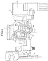
FIG. 4] FIG. 4 is a sectional view along line 4-4 inFIG. 1 . (first embodiment) -
- A
- Throttle body assembly
- B
- Bypass control device
- S
- Offset
- X
- Axis of air intake path
- Y
- Common axis of valve guide hole, control valve, and electric motor
- 1
- Throttle body
- 1a
- Mounting face
- 2
- Air intake path
- 3
- Throttle valve
- 3a
- Valve shaft
- 4
- Throttle drum
- 5
- Control base
- 7
- Valve guide hole
- 9
- Throttle sensor
- 10
- Metering hole
- 11
- Inflow hole
- 12
- Control valve
- 13
- Bypass
- 14
- Upstream passage
- 15
- Downstream passage
- 15a
- Lengthwise hole
- 15b
- Sideways hole
- 15c
- Lengthwise groove
- 16
- First communication groove
- 17
- Second communication groove
- 20
- Electric motor
- 20b
- Output shaft
- 25
- Screw mechanism
- 35
- Air intake tube
- An embodiment of the present invention is explained below by reference to the attached drawings.
- First, in
FIG. 1 to FIG. 3 ,reference numeral 1 is a throttle body that is to be connected to anair intake tube 35 of, for example, an engine for a two-wheeled motor vehicle, and has in its central part anair intake path 2 communicating with the interior of theair intake tube 35, avalve shaft 3a of a butterflytype throttle valve 3 for opening and closing theair intake path 2 being rotatably supported on thethrottle body 1. Fixed to one end part of thevalve shaft 3a is athrottle drum 4 operated by an operator via a throttle wire, and mounted on thethrottle body 1 is athrottle sensor 9 that detects rotation of the other end part of thevalve shaft 3a as a degree of opening of thethrottle valve 3. The above form a throttle body assembly A. - A mounting
face 1a that is parallel to an axis X of theair intake path 2 is formed on one side of thethrottle body 1 between thethrottle drum 4 and thethrottle sensor 9, and acontrol base 5 of a bypass control device B is superimposed on the mountingface 1a and secured by means of a plurality, in the illustrated example a pair, ofbolts 6. Thethrottle body 1 is made of a light alloy and thecontrol base 5 is made of a synthetic resin. - A
bypass 13 is formed so as to extend from thethrottle body 1 to thecontrol base 5 while bypassing thethrottle valve 3 and being connected to theair intake path 2; the arrangement of thebypass 13 is explained below. - Formed in the
throttle body 1 are anupstream passage 14 having its upstream end opening in theair intake path 2 upstream of thethrottle valve 3 and adownstream passage 15 having its downstream end opening in theair intake path 2 downstream of thethrottle valve 3, and formed in the mountingface 1 a are afirst communication groove 16 communicating with the downstream end of theupstream passage 14 and asecond communication groove 17 communicating with the upstream end of thedownstream passage 15. AnO ring 23 surrounding each of the first andsecond communication grooves face 1a, and is in intimate contact with a joining face of thecontrol base 5. - Furthermore, as is clearly shown in
FIG. 2 thedownstream passage 15 is formed from alengthwise hole 15a bending at right angles downward from the downstream end of thesecond communication groove 17 and extending toward theair intake path 2 side, asideways hole 15b bending from the downstream end of thelengthwise hole 15a to the horizontal direction at right angles, and alengthwise groove 15c extending downward from the downstream end of thesideways hole 15b at right angles and reaching theair intake path 2; thelengthwise groove 15c is formed in a joiningend face 1b, to which theair intake tube 35 of the engine is joined, of thethrottle body 1. AnO ring 24 surrounding theair intake path 2 and thelengthwise groove 15c is fitted into the joiningend face 1b and is in intimate contact with a joining end face of theair intake tube 35. - On the other hand, formed in the
control base 5 are avalve guide hole 7 having a rectangular cross-section and having its axis Y pointing in a direction perpendicular to the axis X of theair intake path 2, aninflow hole 11 providing communication between thevalve guide hole 7 and thefirst communication groove 16, and ametering hole 10 providing communication between thevalve guide hole 7 and thesecond communication groove 17. In this way, thebypass 13 is formed from theupstream passage 14, thefirst communication groove 16, theinflow hole 11, thevalve guide hole 7, thesecond communication groove 17, and the downstream passage 15 (lengthwisehole 15a,sideways hole 15b, and lengthwisegroove 15c). - The
metering hole 10 has an elongated hole shape whose major axis points in the direction of the axis Y of thevalve guide hole 7, and acontrol valve 12 that moves between a fully open position A and a fully closed position B (see upper half and lower half inFIG. 3 ) in order to open and close themetering hole 10 is slidably fitted into thevalve guide hole 7. - In this way, the
metering hole 10, which is opened and closed by means of thecontrol valve 12, and the downstream end part of thebypass 13, which opens in theair intake path 2, that is, thelengthwise groove 15c, are disposed so as to have an offset S from each other along the axis X of theair intake path 2, and a passage midway therebetween is formed so as bend. Furthermore, thelengthwise hole 15a in an intermediate part of thedownstream passage 15 is disposed so as to overlap thevalve shaft 3a in a plan view of thethrottle body 1 when viewed from the mountingface 1a side of thethrottle body 1. - The
control valve 12 is formed from acontrol wall 12a having a lower face as a control outsideface 8b that is in sliding contact with a control insideface 8a of thevalve guide hole 7, a pair ofside walls control wall 12a and opposing left and right inside faces of thevalve guide hole 7, afront end wall 12c rising from the front end, on the bottom part side of thevalve guide hole 7, of thecontrol wall 12a and linking front end parts of the twoside walls control wall 12a and the twoside walls control valve 12 forming a box shape with a face on the side opposite to thecontrol wall 12a as anopen face 12e. Thecontrol valve 12 can therefore slide in the axial direction but cannot rotate within thevalve guide hole 7, which has a rectangular cross section. - A
motor mounting hole 19 connected to the open end of thevalve guide hole 7 via astep part 18 and having a larger diameter than that of thevalve guide hole 7 is provided in thecontrol base 5, and astator 20a of anelectric motor 20 is fitted into themotor mounting hole 19. In this arrangement, a seal member 21, made of an elastic material such as a rubber, that is in intimate contact with an outer peripheral face of anoutput shaft 20b of theelectric motor 20 is held between a front end face of thestator 20a and thestep part 18. Theoutput shaft 20b of theelectric motor 20 is capable of forward and reverse rotation, and thecontrol valve 12 is linked to theoutput shaft 20b via ascrew mechanism 25. - The
screw mechanism 25 is formed from aslide piece 27 that is linked to thecontrol valve 12 via rotation-preventing means and that synchronously opens and closes thecontrol valve 12, and a threadedshaft 29 that is provided so as to be connected to theoutput shaft 20b of theelectric motor 20 and that is screwed into a threadedhole 28 provided in theslide piece 27 along the direction in which thecontrol valve 12 slides. The threadedhole 28 is formed into a pouch shape having a dead-end portion 28a. Theslide piece 27 is formed from atubular shaft 27a that extends through the interior of the U-shaped inward collar 12d of thecontrol valve 12 and that is disposed within thecontrol valve 12, and a flange 27c that is formed on the outer periphery of aclosed end wall 27b at the front end of thetubular shaft 27a, thetubular shaft 27a being provided with the pouch-shaped threadedhole 28 into which the threadedshaft 29 is screwed. - A
coil spring 33 is provided in a compressed state between the outward flange 27c and the inward collar 12d, thecontrol valve 12 being urged rearward with respect to theslide piece 27, that is, toward theelectric motor 20, by means of the set load of thecoil spring 33, thereby maintaining a state in which thefront end wall 12c of theslide piece 27 abuts against the outward flange 27c. This enables theslide piece 27 and thecontrol valve 12 to be linked to each other without rattling in the axial direction. - The axis Y of the
valve guide hole 7 thus serves as a common axis Y for thecontrol valve 12, theelectric motor 20, and thescrew mechanism 25 and extends in a direction perpendicular to the axis X of theair intake path 2. - The rotation-preventing means is formed from a
key groove 36 that is formed in an outer end face of theclosed end wall 27b of theslide piece 27 and a key 37 that is projectingly provided on an inner end face of thefront end wall 12c of thecontrol valve 12 and engages with thekey groove 36, relative rotation of theslide piece 27 and thecontrol valve 12 being prevented by engagement between thekey groove 36 and the key 37. The above form the bypass control device B. - The operation of this embodiment is now explained.
- When the
throttle valve 3 is fully closed, an electronic control unit, which is not illustrated, controls energization of theelectric motor 20 so as to rotate theoutput shaft 20b of theelectric motor 20 forward or in reverse in order to obtain the optimum degree of opening of thecontrol valve 12 corresponding to engine operating conditions, such as when the engine is started, when there is fast idling, when there is normal idling, or when there is engine braking based on information about engine operating conditions such as throttle valve degree of opening, engine intake air negative pressure, intake air temperature, engine temperature, and engine rotational speed. When theoutput shaft 20b rotates or in reverse, the rotation is transmitted, while being reduced in speed by means of thescrew mechanism 25, to thecontrol valve 12 via theslide piece 27 as a displacement in the axial direction, and it is therefore possible for thecontrol valve 12 to finely adjust, by means of the axial displacement thereof, the area of themetering hole 10 opening in thevalve guide hole 7. This enables the amount of engine intake air flowing through thebypass 13 to be finely controlled so as to correspond to engine starting, fast idling, normal idling, engine braking, etc. - In particular, since the
metering hole 10 opened and closed by thecontrol valve 12 has an elongated hole shape having its major axis along the direction in which thecontrol valve 12 slides, it is possible to finely adjust the effective opening area according to sliding of thecontrol valve 12. - In this case, acting simultaneously on the
control valve 12 are a pressing force toward the control insideface 8a side by virtue of gravity and an attracting force by virtue of engine intake air negative pressure applied from themetering hole 10 to the control outsideface 8b of thecontrol valve 12, the force putting the control outsideface 8b and the control insideface 8a into intimate contact being increased thereby. - When the
throttle valve 3 is being opened, an amount of intake air corresponding to the degree of opening is supplied to the engine through theair intake path 2, and the engine is shifted to an output operation region. - In such a bypass control device B of the throttle body assembly A, joined to the mounting
face 1a of thethrottle body 1 provided between thethrottle drum 4 and thethrottle sensor 9 is thecontrol base 5, which is a separate body from thethrottle body 1. Formed in the mountingface 1a are thefirst communication groove 16, which communicates with the downstream end of theupstream passage 14 of thebypass 13, and thesecond communication groove 17, which communicates with the upstream end of thedownstream passage 15 of thebypass 13. Formed in thecontrol base 5 are thevalve guide hole 7, theinflow hole 11, which provides communication between thefirst communication groove 16 and thevalve guide hole 7, and themetering hole 10, which provides communication between thesecond communication groove 17 and thevalve guide hole 7 and which is opened and closed by means of thecontrol valve 12. Thevalve guide hole 7, thecontrol valve 12, and theelectric motor 20 are provided so that their common axis Y points in a direction perpendicular to the axis X of theair intake path 2, and themetering hole 10 is formed into an elongated hole shape whose major axis points in the direction of the common axis Y. Thebypass 13 is therefore split and formed by machining thethrottle body 1 and thecontrol base 5, and the machining can be carried out easily. Moreover, since the bypass control device B is formed by incorporating thecontrol valve 12, thescrew mechanism 25, and theelectric motor 20 with thecontrol base 5, separately from the throttle body assembly A, it becomes possible to carry out assembly of the throttle body assembly A and the bypass control device B in parallel, and after assembling them, the two are joined to thus complete the assembly, thereby making the ease of assembly good and the assembly efficiency high. Furthermore, since the bypass control device B is disposed between thethrottle drum 4 and thethrottle sensor 9, the amount of the bypass control device B protruding from the throttle body assembly A can be minimized, thus making the throttle body assembly A with the attached bypass control device B compact. - Furthermore, since, in the
bypass 13, themetering hole 10 and thelengthwise groove 15c are disposed with an offset S from each other along the axis X of theair intake path 2, and thedownstream passage 15 providing a connection therebetween is formed from thelengthwise hole 15a, which bends from the downstream end of thesecond communication groove 17 at right angles and extends toward theair intake path 2 side, thesideways hole 15b, which bends from the downstream end of thelengthwise hole 15a, and thelengthwise groove 15c, which bends from the downstream end of thesideways hole 15b and opens in theair intake path 2, even if blow-back gas of the engine enters thelengthwise groove 15c with a strong force and flows backward in thedownstream passage 15 when for example thethrottle valve 3 is closed and the engine is decelerated, the blow-back gas collides with a plurality of corners while passing through the long flow path until reaching themetering hole 10, thus damping its energy effectively. Moreover, it is difficult for foreign matter such as soot progressing in a direction perpendicular to the axis of themetering hole 10 and along the minor axis of themetering hole 10 to enter themetering hole 10; as a result, foreign matter such as soot contained in the blow-back gas is separated en route, and it is possible to prevent clogging of themetering hole 10 due to foreign matter or problems such as lifting of thecontrol valve 12, which can happen when foreign matter enters themetering hole 10. Furthermore, since it is difficult for foreign matter such as soot to enter themetering hole 10, a long flow path before reaching themetering hole 10 is not needed, and the downstream side of thethrottle body 1 can be made compact. - Furthermore, since the
lengthwise hole 15a of the intermediate part of thedownstream passage 15 is disposed so as to overlap thevalve shaft 3a in a plan view of thethrottle body 1 when viewed from the mountingface 1a side of thethrottle body 1, by disposing thevalve shaft 3a in thethrottle body 1 so as to overlap thelengthwise hole 15a, the distance between thethrottle valve 3 and the joining end face, to which theair intake tube 35 of the engine is joined, becomes small, and the space for placing the air intake tube between the engine and thethrottle valve 3 therefore increases, thus improving the ease of layout of the air intake tube. - The present invention is not limited to the above embodiment and may be modified in a variety of ways as long as the modifications do not depart from the spirit and scope thereof.
Claims (3)
- A throttle body assembly with an attached bypass control device, the throttle body assembly comprising a throttle body (1) having an air intake path (2) that is opened and closed by a throttle valve (3), a valve shaft (3a) of the throttle valve (3) being rotatably supported on the throttle body (1), a throttle drum (4) that is operated by an operator and that is linked to one end part of the valve shaft (3a), and a throttle sensor (9) that detects a rotational angle of the other end part of the valve shaft (3a) as a degree of opening of the throttle valve (3) and that is mounted on the throttle body (1), the bypass control device with which the throttle body assembly is equipped comprising a bypass (13) connected to the air intake path (2) while bypassing the throttle valve (3), a valve guide hole (7) disposed in the bypass (13), a control valve (12) slidably and non-rotatably fitted into the valve guide hole (7) and opening and closing the bypass (13), an electric motor (20) disposed coaxially with the control valve (12), and a screw mechanism (25) converting rotation of an output shaft (20b) of the electric motor (20) into axial movement and transmitting the axial movement to the control valve (12),
characterized in that a control base (5), which is a separate body from the throttle body (1), is joined to a mounting face (1a) formed on one side of the throttle body (1) between the throttle drum (4) and the throttle sensor (9), a first communication groove (16) communicating with a downstream end of an upstream passage (14) of the bypass (13) and a second communication groove (17) communicating with an upstream end of a downstream passage (15) of the bypass (13) are formed in the mounting face (1a), the valve guide hole (7), an inflow hole (11) providing communication between the first communication groove (16) and the valve guide hole (7), and a metering hole (10) providing communication between the second communication groove (17) and the valve guide hole (7) and being opened and closed by the control valve (12) are formed in the control base (5), the valve guide hole (7), the control valve (12), and the electric motor (20) are provided so that a common axis (Y) thereof points in a direction perpendicular to an axis (X) of the air intake path (2), the metering hole (10) is formed into an elongated hole shape whose major axis points in the direction of the common axis (Y), and the metering hole (10) and a downstream end part, opening in the air intake path (2), of the downstream passage (15) are disposed with an offset (S) from each other along the axis (X) of the air intake path (2), a passage midway therebetween being bent. - The throttle body assembly with the attached bypass control device according to Claim 1, wherein
the downstream passage (15) comprises a lengthwise hole (15a) that is bent at right angles from a downstream end of the second communication groove (17) and extends toward the air intake path (2) side, a sideways hole (15b) bending from a downstream end of the lengthwise hole (15a), and a lengthwise groove (15c) bending from a downstream end of the sideways hole (15b) and opening in the air intake path (2), the lengthwise groove (15c) being formed in a joining end face (1b) of the throttle body (1) to which an air intake tube (35) of an engine is joined. - The throttle body assembly with the attached bypass control device according to Claim 2, wherein
the lengthwise hole (15a) is disposed so as to overlap the valve shaft (3a) in a plan view of the throttle body (1) when viewed from the mounting face (1a) side.
Applications Claiming Priority (3)
| Application Number | Priority Date | Filing Date | Title |
|---|---|---|---|
| JP2013052456A JP5963203B2 (en) | 2013-03-14 | 2013-03-14 | Throttle body bypass control device |
| JP2013075680A JP6125297B2 (en) | 2013-04-01 | 2013-04-01 | Throttle body assembly with bypass controller |
| PCT/JP2014/056255 WO2014142093A1 (en) | 2013-03-14 | 2014-03-11 | Throttle body assembly with attached bypass control device |
Publications (3)
| Publication Number | Publication Date |
|---|---|
| EP2975258A1 true EP2975258A1 (en) | 2016-01-20 |
| EP2975258A4 EP2975258A4 (en) | 2016-12-28 |
| EP2975258B1 EP2975258B1 (en) | 2018-05-30 |
Family
ID=51536748
Family Applications (1)
| Application Number | Title | Priority Date | Filing Date |
|---|---|---|---|
| EP14762516.4A Active EP2975258B1 (en) | 2013-03-14 | 2014-03-11 | Throttle body assembly with attached bypass control device |
Country Status (4)
| Country | Link |
|---|---|
| EP (1) | EP2975258B1 (en) |
| CN (1) | CN105008711B (en) |
| BR (1) | BR112015020570B1 (en) |
| WO (1) | WO2014142093A1 (en) |
Families Citing this family (2)
| Publication number | Priority date | Publication date | Assignee | Title |
|---|---|---|---|---|
| JP6963516B2 (en) * | 2018-01-26 | 2021-11-10 | 株式会社ミクニ | Throttle device |
| JP7506629B2 (en) * | 2021-03-25 | 2024-06-26 | 日立Astemo株式会社 | Intake control device |
Family Cites Families (12)
| Publication number | Priority date | Publication date | Assignee | Title |
|---|---|---|---|---|
| JPH0736103Y2 (en) * | 1989-02-01 | 1995-08-16 | 株式会社ユニシアジェックス | Throttle device with air flow meter |
| JPH07247942A (en) * | 1994-03-07 | 1995-09-26 | Aisan Ind Co Ltd | Air volume control device of internal combustion engine |
| JP3974995B2 (en) * | 1998-03-16 | 2007-09-12 | 株式会社ケーヒン | Engine intake air amount control device |
| JP3986850B2 (en) * | 2001-04-27 | 2007-10-03 | 株式会社ケーヒン | Engine intake air amount control device |
| JP4464581B2 (en) * | 2001-05-24 | 2010-05-19 | 本田技研工業株式会社 | Engine intake air amount control device |
| JP3966807B2 (en) * | 2002-12-02 | 2007-08-29 | 株式会社ケーヒン | Engine idle intake control system |
| JP4065281B2 (en) * | 2005-05-20 | 2008-03-19 | 株式会社ケーヒン | Fast idle air volume control device for motorcycle with side stand |
| JP4234121B2 (en) * | 2005-09-02 | 2009-03-04 | 株式会社ケーヒン | Engine intake system |
| JP2007239560A (en) * | 2006-03-07 | 2007-09-20 | Mikuni Corp | Engine control device and motorcycle |
| JP4690950B2 (en) | 2006-06-13 | 2011-06-01 | 株式会社ケーヒン | Engine intake system |
| JP5046736B2 (en) * | 2007-05-09 | 2012-10-10 | 川崎重工業株式会社 | Jet propulsion boat |
| JP4767933B2 (en) * | 2007-11-07 | 2011-09-07 | 株式会社ケーヒン | Bypass intake air amount control device |
-
2014
- 2014-03-11 EP EP14762516.4A patent/EP2975258B1/en active Active
- 2014-03-11 BR BR112015020570-4A patent/BR112015020570B1/en active IP Right Grant
- 2014-03-11 WO PCT/JP2014/056255 patent/WO2014142093A1/en not_active Ceased
- 2014-03-11 CN CN201480013238.6A patent/CN105008711B/en active Active
Also Published As
| Publication number | Publication date |
|---|---|
| BR112015020570A2 (en) | 2017-07-18 |
| BR112015020570B1 (en) | 2022-03-15 |
| EP2975258B1 (en) | 2018-05-30 |
| WO2014142093A1 (en) | 2014-09-18 |
| CN105008711A (en) | 2015-10-28 |
| EP2975258A4 (en) | 2016-12-28 |
| CN105008711B (en) | 2017-11-17 |
Similar Documents
| Publication | Publication Date | Title |
|---|---|---|
| EP1647808A1 (en) | Controller and astride riding type vehicle | |
| EP1647436B1 (en) | Position detection device for an astride riding type vehicle | |
| US7694662B2 (en) | Bypass-intake-flow control apparatus | |
| EP1647435B1 (en) | Position detection device for an astride riding type vehicle | |
| JP2003148303A (en) | Engine intake air control system | |
| EP2975258B1 (en) | Throttle body assembly with attached bypass control device | |
| CN101395360B (en) | Engine control device and two-wheeled vehicle | |
| JP5299390B2 (en) | Turbocharger | |
| EP2957747B1 (en) | Flow volume control device | |
| JP6915495B2 (en) | Actuator | |
| CN104234878A (en) | EGR (Exhaust Gas Recirculation) valve driven by motor | |
| JP5727620B2 (en) | Engine intake control device | |
| EP3845751A1 (en) | Throttle body assembly for unitary combustion chamber | |
| KR101518668B1 (en) | Valve drive apparatus and supercharger having the same | |
| JP5943007B2 (en) | Sensor module | |
| CN104271932B (en) | Mixing valve of an internal combustion engine | |
| JP2009185679A (en) | Electronic throttle device for internal combustion engines | |
| JP6125297B2 (en) | Throttle body assembly with bypass controller | |
| EP1867852B1 (en) | Engine intake system | |
| TW533264B (en) | Seal structure in bypass intake control system | |
| CN101253325B (en) | Air intake device for engine | |
| EP1811153A2 (en) | Air intake system in engine | |
| JP2016020665A (en) | Exhaust control valve | |
| JP4188397B2 (en) | Engine intake system | |
| JP6029208B2 (en) | Engine intake air amount control device |
Legal Events
| Date | Code | Title | Description |
|---|---|---|---|
| PUAI | Public reference made under article 153(3) epc to a published international application that has entered the european phase |
Free format text: ORIGINAL CODE: 0009012 |
|
| 17P | Request for examination filed |
Effective date: 20151006 |
|
| AK | Designated contracting states |
Kind code of ref document: A1 Designated state(s): AL AT BE BG CH CY CZ DE DK EE ES FI FR GB GR HR HU IE IS IT LI LT LU LV MC MK MT NL NO PL PT RO RS SE SI SK SM TR |
|
| AX | Request for extension of the european patent |
Extension state: BA ME |
|
| DAX | Request for extension of the european patent (deleted) | ||
| A4 | Supplementary search report drawn up and despatched |
Effective date: 20161125 |
|
| RIC1 | Information provided on ipc code assigned before grant |
Ipc: F02D 9/10 20060101ALI20161121BHEP Ipc: F02M 69/32 20060101AFI20161121BHEP |
|
| GRAP | Despatch of communication of intention to grant a patent |
Free format text: ORIGINAL CODE: EPIDOSNIGR1 |
|
| STAA | Information on the status of an ep patent application or granted ep patent |
Free format text: STATUS: GRANT OF PATENT IS INTENDED |
|
| INTG | Intention to grant announced |
Effective date: 20171212 |
|
| GRAS | Grant fee paid |
Free format text: ORIGINAL CODE: EPIDOSNIGR3 |
|
| GRAA | (expected) grant |
Free format text: ORIGINAL CODE: 0009210 |
|
| STAA | Information on the status of an ep patent application or granted ep patent |
Free format text: STATUS: THE PATENT HAS BEEN GRANTED |
|
| AK | Designated contracting states |
Kind code of ref document: B1 Designated state(s): AL AT BE BG CH CY CZ DE DK EE ES FI FR GB GR HR HU IE IS IT LI LT LU LV MC MK MT NL NO PL PT RO RS SE SI SK SM TR |
|
| REG | Reference to a national code |
Ref country code: GB Ref legal event code: FG4D |
|
| REG | Reference to a national code |
Ref country code: CH Ref legal event code: EP |
|
| REG | Reference to a national code |
Ref country code: AT Ref legal event code: REF Ref document number: 1003856 Country of ref document: AT Kind code of ref document: T Effective date: 20180615 |
|
| REG | Reference to a national code |
Ref country code: DE Ref legal event code: R096 Ref document number: 602014026285 Country of ref document: DE |
|
| REG | Reference to a national code |
Ref country code: IE Ref legal event code: FG4D |
|
| REG | Reference to a national code |
Ref country code: NL Ref legal event code: MP Effective date: 20180530 |
|
| REG | Reference to a national code |
Ref country code: LT Ref legal event code: MG4D |
|
| PG25 | Lapsed in a contracting state [announced via postgrant information from national office to epo] |
Ref country code: FI Free format text: LAPSE BECAUSE OF FAILURE TO SUBMIT A TRANSLATION OF THE DESCRIPTION OR TO PAY THE FEE WITHIN THE PRESCRIBED TIME-LIMIT Effective date: 20180530 Ref country code: BG Free format text: LAPSE BECAUSE OF FAILURE TO SUBMIT A TRANSLATION OF THE DESCRIPTION OR TO PAY THE FEE WITHIN THE PRESCRIBED TIME-LIMIT Effective date: 20180830 Ref country code: LT Free format text: LAPSE BECAUSE OF FAILURE TO SUBMIT A TRANSLATION OF THE DESCRIPTION OR TO PAY THE FEE WITHIN THE PRESCRIBED TIME-LIMIT Effective date: 20180530 Ref country code: CY Free format text: LAPSE BECAUSE OF FAILURE TO SUBMIT A TRANSLATION OF THE DESCRIPTION OR TO PAY THE FEE WITHIN THE PRESCRIBED TIME-LIMIT Effective date: 20180530 Ref country code: SE Free format text: LAPSE BECAUSE OF FAILURE TO SUBMIT A TRANSLATION OF THE DESCRIPTION OR TO PAY THE FEE WITHIN THE PRESCRIBED TIME-LIMIT Effective date: 20180530 Ref country code: NO Free format text: LAPSE BECAUSE OF FAILURE TO SUBMIT A TRANSLATION OF THE DESCRIPTION OR TO PAY THE FEE WITHIN THE PRESCRIBED TIME-LIMIT Effective date: 20180830 Ref country code: ES Free format text: LAPSE BECAUSE OF FAILURE TO SUBMIT A TRANSLATION OF THE DESCRIPTION OR TO PAY THE FEE WITHIN THE PRESCRIBED TIME-LIMIT Effective date: 20180530 |
|
| PG25 | Lapsed in a contracting state [announced via postgrant information from national office to epo] |
Ref country code: GR Free format text: LAPSE BECAUSE OF FAILURE TO SUBMIT A TRANSLATION OF THE DESCRIPTION OR TO PAY THE FEE WITHIN THE PRESCRIBED TIME-LIMIT Effective date: 20180831 Ref country code: LV Free format text: LAPSE BECAUSE OF FAILURE TO SUBMIT A TRANSLATION OF THE DESCRIPTION OR TO PAY THE FEE WITHIN THE PRESCRIBED TIME-LIMIT Effective date: 20180530 Ref country code: HR Free format text: LAPSE BECAUSE OF FAILURE TO SUBMIT A TRANSLATION OF THE DESCRIPTION OR TO PAY THE FEE WITHIN THE PRESCRIBED TIME-LIMIT Effective date: 20180530 Ref country code: RS Free format text: LAPSE BECAUSE OF FAILURE TO SUBMIT A TRANSLATION OF THE DESCRIPTION OR TO PAY THE FEE WITHIN THE PRESCRIBED TIME-LIMIT Effective date: 20180530 |
|
| REG | Reference to a national code |
Ref country code: AT Ref legal event code: MK05 Ref document number: 1003856 Country of ref document: AT Kind code of ref document: T Effective date: 20180530 |
|
| PG25 | Lapsed in a contracting state [announced via postgrant information from national office to epo] |
Ref country code: NL Free format text: LAPSE BECAUSE OF FAILURE TO SUBMIT A TRANSLATION OF THE DESCRIPTION OR TO PAY THE FEE WITHIN THE PRESCRIBED TIME-LIMIT Effective date: 20180530 |
|
| PG25 | Lapsed in a contracting state [announced via postgrant information from national office to epo] |
Ref country code: SK Free format text: LAPSE BECAUSE OF FAILURE TO SUBMIT A TRANSLATION OF THE DESCRIPTION OR TO PAY THE FEE WITHIN THE PRESCRIBED TIME-LIMIT Effective date: 20180530 Ref country code: EE Free format text: LAPSE BECAUSE OF FAILURE TO SUBMIT A TRANSLATION OF THE DESCRIPTION OR TO PAY THE FEE WITHIN THE PRESCRIBED TIME-LIMIT Effective date: 20180530 Ref country code: CZ Free format text: LAPSE BECAUSE OF FAILURE TO SUBMIT A TRANSLATION OF THE DESCRIPTION OR TO PAY THE FEE WITHIN THE PRESCRIBED TIME-LIMIT Effective date: 20180530 Ref country code: RO Free format text: LAPSE BECAUSE OF FAILURE TO SUBMIT A TRANSLATION OF THE DESCRIPTION OR TO PAY THE FEE WITHIN THE PRESCRIBED TIME-LIMIT Effective date: 20180530 Ref country code: DK Free format text: LAPSE BECAUSE OF FAILURE TO SUBMIT A TRANSLATION OF THE DESCRIPTION OR TO PAY THE FEE WITHIN THE PRESCRIBED TIME-LIMIT Effective date: 20180530 Ref country code: AT Free format text: LAPSE BECAUSE OF FAILURE TO SUBMIT A TRANSLATION OF THE DESCRIPTION OR TO PAY THE FEE WITHIN THE PRESCRIBED TIME-LIMIT Effective date: 20180530 Ref country code: PL Free format text: LAPSE BECAUSE OF FAILURE TO SUBMIT A TRANSLATION OF THE DESCRIPTION OR TO PAY THE FEE WITHIN THE PRESCRIBED TIME-LIMIT Effective date: 20180530 |
|
| PG25 | Lapsed in a contracting state [announced via postgrant information from national office to epo] |
Ref country code: SM Free format text: LAPSE BECAUSE OF FAILURE TO SUBMIT A TRANSLATION OF THE DESCRIPTION OR TO PAY THE FEE WITHIN THE PRESCRIBED TIME-LIMIT Effective date: 20180530 |
|
| REG | Reference to a national code |
Ref country code: DE Ref legal event code: R097 Ref document number: 602014026285 Country of ref document: DE |
|
| PLBE | No opposition filed within time limit |
Free format text: ORIGINAL CODE: 0009261 |
|
| STAA | Information on the status of an ep patent application or granted ep patent |
Free format text: STATUS: NO OPPOSITION FILED WITHIN TIME LIMIT |
|
| 26N | No opposition filed |
Effective date: 20190301 |
|
| PG25 | Lapsed in a contracting state [announced via postgrant information from national office to epo] |
Ref country code: SI Free format text: LAPSE BECAUSE OF FAILURE TO SUBMIT A TRANSLATION OF THE DESCRIPTION OR TO PAY THE FEE WITHIN THE PRESCRIBED TIME-LIMIT Effective date: 20180530 |
|
| PG25 | Lapsed in a contracting state [announced via postgrant information from national office to epo] |
Ref country code: MC Free format text: LAPSE BECAUSE OF FAILURE TO SUBMIT A TRANSLATION OF THE DESCRIPTION OR TO PAY THE FEE WITHIN THE PRESCRIBED TIME-LIMIT Effective date: 20180530 |
|
| REG | Reference to a national code |
Ref country code: CH Ref legal event code: PL |
|
| GBPC | Gb: european patent ceased through non-payment of renewal fee |
Effective date: 20190311 |
|
| PG25 | Lapsed in a contracting state [announced via postgrant information from national office to epo] |
Ref country code: AL Free format text: LAPSE BECAUSE OF FAILURE TO SUBMIT A TRANSLATION OF THE DESCRIPTION OR TO PAY THE FEE WITHIN THE PRESCRIBED TIME-LIMIT Effective date: 20180530 Ref country code: LU Free format text: LAPSE BECAUSE OF NON-PAYMENT OF DUE FEES Effective date: 20190311 |
|
| REG | Reference to a national code |
Ref country code: BE Ref legal event code: MM Effective date: 20190331 |
|
| PG25 | Lapsed in a contracting state [announced via postgrant information from national office to epo] |
Ref country code: GB Free format text: LAPSE BECAUSE OF NON-PAYMENT OF DUE FEES Effective date: 20190311 Ref country code: IE Free format text: LAPSE BECAUSE OF NON-PAYMENT OF DUE FEES Effective date: 20190311 Ref country code: LI Free format text: LAPSE BECAUSE OF NON-PAYMENT OF DUE FEES Effective date: 20190331 Ref country code: CH Free format text: LAPSE BECAUSE OF NON-PAYMENT OF DUE FEES Effective date: 20190331 |
|
| PG25 | Lapsed in a contracting state [announced via postgrant information from national office to epo] |
Ref country code: BE Free format text: LAPSE BECAUSE OF NON-PAYMENT OF DUE FEES Effective date: 20190331 Ref country code: FR Free format text: LAPSE BECAUSE OF NON-PAYMENT OF DUE FEES Effective date: 20190331 |
|
| PG25 | Lapsed in a contracting state [announced via postgrant information from national office to epo] |
Ref country code: TR Free format text: LAPSE BECAUSE OF FAILURE TO SUBMIT A TRANSLATION OF THE DESCRIPTION OR TO PAY THE FEE WITHIN THE PRESCRIBED TIME-LIMIT Effective date: 20180530 |
|
| PG25 | Lapsed in a contracting state [announced via postgrant information from national office to epo] |
Ref country code: PT Free format text: LAPSE BECAUSE OF FAILURE TO SUBMIT A TRANSLATION OF THE DESCRIPTION OR TO PAY THE FEE WITHIN THE PRESCRIBED TIME-LIMIT Effective date: 20181001 Ref country code: MT Free format text: LAPSE BECAUSE OF NON-PAYMENT OF DUE FEES Effective date: 20190311 |
|
| PG25 | Lapsed in a contracting state [announced via postgrant information from national office to epo] |
Ref country code: IS Free format text: LAPSE BECAUSE OF FAILURE TO SUBMIT A TRANSLATION OF THE DESCRIPTION OR TO PAY THE FEE WITHIN THE PRESCRIBED TIME-LIMIT Effective date: 20180930 |
|
| PG25 | Lapsed in a contracting state [announced via postgrant information from national office to epo] |
Ref country code: HU Free format text: LAPSE BECAUSE OF FAILURE TO SUBMIT A TRANSLATION OF THE DESCRIPTION OR TO PAY THE FEE WITHIN THE PRESCRIBED TIME-LIMIT; INVALID AB INITIO Effective date: 20140311 |
|
| REG | Reference to a national code |
Ref country code: DE Ref legal event code: R081 Ref document number: 602014026285 Country of ref document: DE Owner name: HITACHI ASTEMO, LTD., HITACHINAKA-SHI, JP Free format text: FORMER OWNER: KEIHIN CORPORATION, TOKYO, JP |
|
| PG25 | Lapsed in a contracting state [announced via postgrant information from national office to epo] |
Ref country code: MK Free format text: LAPSE BECAUSE OF FAILURE TO SUBMIT A TRANSLATION OF THE DESCRIPTION OR TO PAY THE FEE WITHIN THE PRESCRIBED TIME-LIMIT Effective date: 20180530 |
|
| PGFP | Annual fee paid to national office [announced via postgrant information from national office to epo] |
Ref country code: DE Payment date: 20260128 Year of fee payment: 13 |
|
| PGFP | Annual fee paid to national office [announced via postgrant information from national office to epo] |
Ref country code: IT Payment date: 20260220 Year of fee payment: 13 |