EP2975225A1 - Steam turbine vane manufacturing method - Google Patents
Steam turbine vane manufacturing method Download PDFInfo
- Publication number
- EP2975225A1 EP2975225A1 EP14764425.6A EP14764425A EP2975225A1 EP 2975225 A1 EP2975225 A1 EP 2975225A1 EP 14764425 A EP14764425 A EP 14764425A EP 2975225 A1 EP2975225 A1 EP 2975225A1
- Authority
- EP
- European Patent Office
- Prior art keywords
- steam turbine
- turbine vane
- protective part
- build
- subjected
- Prior art date
- Legal status (The legal status is an assumption and is not a legal conclusion. Google has not performed a legal analysis and makes no representation as to the accuracy of the status listed.)
- Granted
Links
- 238000004519 manufacturing process Methods 0.000 title claims abstract description 69
- 239000000463 material Substances 0.000 claims abstract description 115
- 230000001681 protective effect Effects 0.000 claims abstract description 67
- 238000003466 welding Methods 0.000 claims abstract description 31
- 239000011324 bead Substances 0.000 claims abstract description 29
- 238000005520 cutting process Methods 0.000 claims abstract description 13
- 238000005242 forging Methods 0.000 claims description 40
- 230000032683 aging Effects 0.000 claims description 12
- 239000000758 substrate Substances 0.000 abstract 1
- 238000010438 heat treatment Methods 0.000 description 10
- 229910001347 Stellite Inorganic materials 0.000 description 7
- AHICWQREWHDHHF-UHFFFAOYSA-N chromium;cobalt;iron;manganese;methane;molybdenum;nickel;silicon;tungsten Chemical compound C.[Si].[Cr].[Mn].[Fe].[Co].[Ni].[Mo].[W] AHICWQREWHDHHF-UHFFFAOYSA-N 0.000 description 7
- 230000003628 erosive effect Effects 0.000 description 5
- 238000005219 brazing Methods 0.000 description 4
- 239000002184 metal Substances 0.000 description 4
- 230000000052 comparative effect Effects 0.000 description 3
- 238000005304 joining Methods 0.000 description 3
- 238000005498 polishing Methods 0.000 description 3
- 239000007787 solid Substances 0.000 description 3
- 230000006641 stabilisation Effects 0.000 description 3
- 238000011105 stabilization Methods 0.000 description 3
- 229910000963 austenitic stainless steel Inorganic materials 0.000 description 1
- 230000000694 effects Effects 0.000 description 1
- 239000000945 filler Substances 0.000 description 1
- XLYOFNOQVPJJNP-UHFFFAOYSA-N water Substances O XLYOFNOQVPJJNP-UHFFFAOYSA-N 0.000 description 1
Images



Classifications
-
- F—MECHANICAL ENGINEERING; LIGHTING; HEATING; WEAPONS; BLASTING
- F01—MACHINES OR ENGINES IN GENERAL; ENGINE PLANTS IN GENERAL; STEAM ENGINES
- F01D—NON-POSITIVE DISPLACEMENT MACHINES OR ENGINES, e.g. STEAM TURBINES
- F01D5/00—Blades; Blade-carrying members; Heating, heat-insulating, cooling or antivibration means on the blades or the members
- F01D5/12—Blades
- F01D5/28—Selecting particular materials; Particular measures relating thereto; Measures against erosion or corrosion
- F01D5/288—Protective coatings for blades
-
- B—PERFORMING OPERATIONS; TRANSPORTING
- B23—MACHINE TOOLS; METAL-WORKING NOT OTHERWISE PROVIDED FOR
- B23K—SOLDERING OR UNSOLDERING; WELDING; CLADDING OR PLATING BY SOLDERING OR WELDING; CUTTING BY APPLYING HEAT LOCALLY, e.g. FLAME CUTTING; WORKING BY LASER BEAM
- B23K26/00—Working by laser beam, e.g. welding, cutting or boring
- B23K26/34—Laser welding for purposes other than joining
- B23K26/342—Build-up welding
-
- B—PERFORMING OPERATIONS; TRANSPORTING
- B23—MACHINE TOOLS; METAL-WORKING NOT OTHERWISE PROVIDED FOR
- B23K—SOLDERING OR UNSOLDERING; WELDING; CLADDING OR PLATING BY SOLDERING OR WELDING; CUTTING BY APPLYING HEAT LOCALLY, e.g. FLAME CUTTING; WORKING BY LASER BEAM
- B23K26/00—Working by laser beam, e.g. welding, cutting or boring
- B23K26/36—Removing material
- B23K26/38—Removing material by boring or cutting
-
- B—PERFORMING OPERATIONS; TRANSPORTING
- B23—MACHINE TOOLS; METAL-WORKING NOT OTHERWISE PROVIDED FOR
- B23P—METAL-WORKING NOT OTHERWISE PROVIDED FOR; COMBINED OPERATIONS; UNIVERSAL MACHINE TOOLS
- B23P15/00—Making specific metal objects by operations not covered by a single other subclass or a group in this subclass
- B23P15/04—Making specific metal objects by operations not covered by a single other subclass or a group in this subclass turbine or like blades from several pieces
-
- F—MECHANICAL ENGINEERING; LIGHTING; HEATING; WEAPONS; BLASTING
- F01—MACHINES OR ENGINES IN GENERAL; ENGINE PLANTS IN GENERAL; STEAM ENGINES
- F01D—NON-POSITIVE DISPLACEMENT MACHINES OR ENGINES, e.g. STEAM TURBINES
- F01D5/00—Blades; Blade-carrying members; Heating, heat-insulating, cooling or antivibration means on the blades or the members
- F01D5/12—Blades
- F01D5/14—Form or construction
- F01D5/147—Construction, i.e. structural features, e.g. of weight-saving hollow blades
-
- F—MECHANICAL ENGINEERING; LIGHTING; HEATING; WEAPONS; BLASTING
- F01—MACHINES OR ENGINES IN GENERAL; ENGINE PLANTS IN GENERAL; STEAM ENGINES
- F01D—NON-POSITIVE DISPLACEMENT MACHINES OR ENGINES, e.g. STEAM TURBINES
- F01D5/00—Blades; Blade-carrying members; Heating, heat-insulating, cooling or antivibration means on the blades or the members
- F01D5/12—Blades
- F01D5/28—Selecting particular materials; Particular measures relating thereto; Measures against erosion or corrosion
- F01D5/286—Particular treatment of blades, e.g. to increase durability or resistance against corrosion or erosion
-
- F—MECHANICAL ENGINEERING; LIGHTING; HEATING; WEAPONS; BLASTING
- F01—MACHINES OR ENGINES IN GENERAL; ENGINE PLANTS IN GENERAL; STEAM ENGINES
- F01D—NON-POSITIVE DISPLACEMENT MACHINES OR ENGINES, e.g. STEAM TURBINES
- F01D9/00—Stators
- F01D9/02—Nozzles; Nozzle boxes; Stator blades; Guide conduits, e.g. individual nozzles
-
- B—PERFORMING OPERATIONS; TRANSPORTING
- B23—MACHINE TOOLS; METAL-WORKING NOT OTHERWISE PROVIDED FOR
- B23K—SOLDERING OR UNSOLDERING; WELDING; CLADDING OR PLATING BY SOLDERING OR WELDING; CUTTING BY APPLYING HEAT LOCALLY, e.g. FLAME CUTTING; WORKING BY LASER BEAM
- B23K2101/00—Articles made by soldering, welding or cutting
- B23K2101/001—Turbines
-
- F—MECHANICAL ENGINEERING; LIGHTING; HEATING; WEAPONS; BLASTING
- F05—INDEXING SCHEMES RELATING TO ENGINES OR PUMPS IN VARIOUS SUBCLASSES OF CLASSES F01-F04
- F05D—INDEXING SCHEME FOR ASPECTS RELATING TO NON-POSITIVE-DISPLACEMENT MACHINES OR ENGINES, GAS-TURBINES OR JET-PROPULSION PLANTS
- F05D2220/00—Application
- F05D2220/30—Application in turbines
- F05D2220/31—Application in turbines in steam turbines
-
- F—MECHANICAL ENGINEERING; LIGHTING; HEATING; WEAPONS; BLASTING
- F05—INDEXING SCHEMES RELATING TO ENGINES OR PUMPS IN VARIOUS SUBCLASSES OF CLASSES F01-F04
- F05D—INDEXING SCHEME FOR ASPECTS RELATING TO NON-POSITIVE-DISPLACEMENT MACHINES OR ENGINES, GAS-TURBINES OR JET-PROPULSION PLANTS
- F05D2230/00—Manufacture
- F05D2230/10—Manufacture by removing material
-
- F—MECHANICAL ENGINEERING; LIGHTING; HEATING; WEAPONS; BLASTING
- F05—INDEXING SCHEMES RELATING TO ENGINES OR PUMPS IN VARIOUS SUBCLASSES OF CLASSES F01-F04
- F05D—INDEXING SCHEME FOR ASPECTS RELATING TO NON-POSITIVE-DISPLACEMENT MACHINES OR ENGINES, GAS-TURBINES OR JET-PROPULSION PLANTS
- F05D2230/00—Manufacture
- F05D2230/20—Manufacture essentially without removing material
- F05D2230/25—Manufacture essentially without removing material by forging
-
- F—MECHANICAL ENGINEERING; LIGHTING; HEATING; WEAPONS; BLASTING
- F05—INDEXING SCHEMES RELATING TO ENGINES OR PUMPS IN VARIOUS SUBCLASSES OF CLASSES F01-F04
- F05D—INDEXING SCHEME FOR ASPECTS RELATING TO NON-POSITIVE-DISPLACEMENT MACHINES OR ENGINES, GAS-TURBINES OR JET-PROPULSION PLANTS
- F05D2230/00—Manufacture
- F05D2230/30—Manufacture with deposition of material
-
- F—MECHANICAL ENGINEERING; LIGHTING; HEATING; WEAPONS; BLASTING
- F05—INDEXING SCHEMES RELATING TO ENGINES OR PUMPS IN VARIOUS SUBCLASSES OF CLASSES F01-F04
- F05D—INDEXING SCHEME FOR ASPECTS RELATING TO NON-POSITIVE-DISPLACEMENT MACHINES OR ENGINES, GAS-TURBINES OR JET-PROPULSION PLANTS
- F05D2230/00—Manufacture
- F05D2230/30—Manufacture with deposition of material
- F05D2230/31—Layer deposition
-
- F—MECHANICAL ENGINEERING; LIGHTING; HEATING; WEAPONS; BLASTING
- F05—INDEXING SCHEMES RELATING TO ENGINES OR PUMPS IN VARIOUS SUBCLASSES OF CLASSES F01-F04
- F05D—INDEXING SCHEME FOR ASPECTS RELATING TO NON-POSITIVE-DISPLACEMENT MACHINES OR ENGINES, GAS-TURBINES OR JET-PROPULSION PLANTS
- F05D2230/00—Manufacture
- F05D2230/90—Coating; Surface treatment
-
- F—MECHANICAL ENGINEERING; LIGHTING; HEATING; WEAPONS; BLASTING
- F05—INDEXING SCHEMES RELATING TO ENGINES OR PUMPS IN VARIOUS SUBCLASSES OF CLASSES F01-F04
- F05D—INDEXING SCHEME FOR ASPECTS RELATING TO NON-POSITIVE-DISPLACEMENT MACHINES OR ENGINES, GAS-TURBINES OR JET-PROPULSION PLANTS
- F05D2240/00—Components
- F05D2240/10—Stators
- F05D2240/12—Fluid guiding means, e.g. vanes
-
- F—MECHANICAL ENGINEERING; LIGHTING; HEATING; WEAPONS; BLASTING
- F05—INDEXING SCHEMES RELATING TO ENGINES OR PUMPS IN VARIOUS SUBCLASSES OF CLASSES F01-F04
- F05D—INDEXING SCHEME FOR ASPECTS RELATING TO NON-POSITIVE-DISPLACEMENT MACHINES OR ENGINES, GAS-TURBINES OR JET-PROPULSION PLANTS
- F05D2240/00—Components
- F05D2240/20—Rotors
- F05D2240/30—Characteristics of rotor blades, i.e. of any element transforming dynamic fluid energy to or from rotational energy and being attached to a rotor
- F05D2240/303—Characteristics of rotor blades, i.e. of any element transforming dynamic fluid energy to or from rotational energy and being attached to a rotor related to the leading edge of a rotor blade
-
- F—MECHANICAL ENGINEERING; LIGHTING; HEATING; WEAPONS; BLASTING
- F05—INDEXING SCHEMES RELATING TO ENGINES OR PUMPS IN VARIOUS SUBCLASSES OF CLASSES F01-F04
- F05D—INDEXING SCHEME FOR ASPECTS RELATING TO NON-POSITIVE-DISPLACEMENT MACHINES OR ENGINES, GAS-TURBINES OR JET-PROPULSION PLANTS
- F05D2240/00—Components
- F05D2240/20—Rotors
- F05D2240/30—Characteristics of rotor blades, i.e. of any element transforming dynamic fluid energy to or from rotational energy and being attached to a rotor
- F05D2240/307—Characteristics of rotor blades, i.e. of any element transforming dynamic fluid energy to or from rotational energy and being attached to a rotor related to the tip of a rotor blade
Definitions
- the present invention relates to a steam turbine vane manufacturing method and in particular, to a steam turbine vane manufacturing method which is utilized when producing a steam turbine vane with which a steam turbine is provided.
- a steam turbine which generates power by receiving high-temperature and high-pressure steam in a steam turbine vane. Water droplets contained in the steam come into contact with the steam turbine vane, whereby erosion sometimes occurs (refer to PTL 1).
- a measure against erosion which prevents erosion of a main body portion of a steam turbine vane by forming a protective part at a portion of the steam turbine vane. It is desirable to appropriately manufacture the steam turbine vane with such a measure against erosion applied thereto.
- An object of the present invention is to provide a steam turbine vane manufacturing method of appropriately manufacturing a steam turbine vane.
- a steam turbine vane manufacturing method including: a groove processing step of forming a protective part joint surface in a steam turbine vane material; a build-up welding step of forming a protective part build-up bead on the protective part joint surface by build-up welding; and a processing step of processing the steam turbine vane material into a steam turbine vane by cutting the protective part build-up bead along with the steam turbine vane material.
- the steam turbine vane material is larger than a steam turbine vane material after finishing processing in which a steam turbine vane material has been subjected to finishing processing, and thus is not easily deformed by heat input due to build-up welding, as compared to the steam turbine vane material after finishing processing.
- a steam turbine vane manufacturing method as compared to another steam turbine vane manufacturing method in which a protective part build-up bead is formed after a steam turbine vane material is subjected to finishing processing, it is possible to reduce the deformation amount of the steam turbine vane material which is deformed by build-up welding, and thus it is possible to appropriately manufacture a steam turbine vane.
- the steam turbine vane manufacturing method further includes: a forging step of manufacturing the steam turbine vane material by forging.
- the steam turbine vane material manufactured by forging is larger than a steam turbine vane material after rough processing formed by performing cutting on a forged part, and thus is not easily deformed by heat input due to build-up welding. For this reason, in such a steam turbine vane manufacturing method, as compared to another steam turbine vane manufacturing method in which a protective part build-up bead is formed on a protective part joint surface which is formed in the steam turbine vane material after rough processing, it is possible to reduce the deformation amount of the steam turbine vane material which is deformed by build-up welding, and thus it is possible to appropriately manufacture a steam turbine vane.
- the steam turbine vane manufacturing method further includes: an aging treatment step of performing aging treatment on the steam turbine vane material along with the protective part build-up bead before the processing step is carried out.
- the steam turbine vane material is hardened by being subjected to aging treatment, and thus it is possible to easily perform straightening on the steam turbine vane material before it is cut, and thus it is possible to easily manufacture a steam turbine vane.
- a steam turbine vane which is manufactured by carrying out the steam turbine vane manufacturing method according to the present invention.
- a steam turbine vane which is manufactured by carrying out the steam turbine vane manufacturing method according to the present invention.
- a protective part build-up bead is formed after a steam turbine vane material is subjected to finishing processing, it is possible to reduce the deformation amount of the steam turbine vane material which is deformed by build-up welding, and thus it is possible to appropriately manufacture the steam turbine vane.
- a steam turbine vane 1 is utilized in a steam turbine and provided with a root section 2 and an aerofoil profile section 3, as shown in Fig. 1 .
- the root section 2 is mounted on a rotor of a steam turbine.
- the aerofoil profile section 3 is formed in an aerofoil profile and fixed to the root section 2. The aerofoil profile section 3 is exposed to steam flowing through the steam turbine when the root section 2 is mounted on the rotor of the steam turbine.
- the aerofoil profile section 3 is provided with a main body portion 5 and a protective part 6.
- the main body portion 5 is formed in a substantially aerofoil profile and formed integrally with the root section 2, thereby being fixed to the root section 2.
- the protective part 6 is formed of Stellite (registered trademark). The protective part 6 is joined to the main body portion 5 so as to form a leading edge portion of an airfoil tip of the aerofoil profile section 3.
- An embodiment of a steam turbine vane manufacturing method is utilized when manufacturing the steam turbine vane 1.
- a steam turbine vane material after forging is manufactured by forging a solid metal blank (Step S1).
- the steam turbine vane material after forging is formed in a predetermined shape with high accuracy by being further subjected to coining.
- the steam turbine vane material after forging is formed in a predetermined shape with higher accuracy by being subjected to hot straightening (Step S2).
- the steam turbine vane material after forging is subjected to solution heat treatment. After the solution heat treatment, the steam turbine vane material after forging is subjected to stabilization heat treatment (Step S3). After the heat treatment, the steam turbine vane material after forging is further subjected to aging treatment, thereby being hardened (Step S4).
- the steam turbine vane material after forging is subjected to straightening so as to be formed in a predetermined shape. After the straightening, the steam turbine vane material after forging is subjected to cutting, thereby being formed into a steam turbine vane material after rough processing (Step S5). As shown in Fig. 3 , most of the surface formed in a steam turbine vane material after forging 12 is removed by cutting, and thus a steam turbine vane material after rough processing 11 is smaller than the steam turbine vane material after forging 12.
- the steam turbine vane material after rough processing 11 is further subjected to cutting, whereby a protective part joint surface 14 is formed (Step S6).
- the protective part joint surface 14 is formed in an area corresponding to a leading edge portion of the steam turbine vane 1, of the steam turbine vane material after rough processing 11, and formed to be concave.
- the protective part build-up bead 15 is formed by the build-up welding (Step S7).
- the protective part build-up bead 15 is formed of Stellite (registered trademark) and solidly joined to the protective part joint surface 14.
- the protective part build-up bead 15 is formed in an area corresponding to the leading edge portion of the steam turbine vane 1, of the steam turbine vane material after rough processing 11, and formed as a projection.
- the steam turbine vane material after rough processing 11 is subjected to straightening so as to be formed in a predetermined shape. After the straightening, the steam turbine vane material after rough processing 11 is subjected to cutting, thereby being formed into a steam turbine vane material after finishing processing 16 (Step S8).
- the steam turbine vane material after finishing processing 16 is formed such that most of the surface of the steam turbine vane material after rough processing 11 is removed and such that most of the surface of the protective part build-up bead 15 is removed. For this reason, the steam turbine vane material after finishing processing 16 is smaller than the steam turbine vane material after rough processing 11.
- the steam turbine vane material after finishing processing 16 is subjected to polishing, thereby being formed into the steam turbine vane 1 (Step S9).
- the steam turbine vane 1 is manufactured in this manner, whereby a portion of the protective part build-up bead 15 is formed into the protective part 6.
- the steam turbine vane 1 is manufactured by joining a Stellite plate to the protective part joint surface 14 of the steam turbine vane material after finishing processing 16 by brazing.
- the protective part joint surface 14 it is necessary for the protective part joint surface 14 to be sufficiently heated, and thus it is necessary to heat the surface on the side opposite to the protective part joint surface 14, of a base material. For this reason, the amount of heat which is input to the base material due to the brazing is relatively large.
- the protective part build-up bead 15 is formed by build-up welding, whereby it is not necessary to heat the surface on the side opposite to the protective part joint surface 14, of the steam turbine vane material after rough processing 11. For this reason, in this steam turbine vane manufacturing method, as compared to the steam turbine vane manufacturing method of the comparative example in which the steam turbine vane is manufactured by joining the Stellite plate to the protective part joint surface 14 by brazing, it is possible to reduce the amount of heat which is input to the steam turbine vane material after rough processing 11. As a result, in this steam turbine vane manufacturing method, as compared to the comparative example, it is possible to reduce the deformation amount of the steam turbine vane material after rough processing 11, and thus it is possible to more appropriately manufacture the steam turbine vane 1.
- the deformation amount of a relatively large base material which is deformed by build-up welding is smaller than the deformation amount of a relatively small base material which is deformed by build-up welding.
- the protective part build-up bead 15 is formed on the protective part joint surface 14 of the steam turbine vane material after rough processing 11, whereby the deformation amount of the base material can be reduced, as compared to a case of forming the protective part build-up bead 15 on the protective part joint surface 14 of the steam turbine vane material after finishing processing 16.
- this steam turbine vane manufacturing method it is possible to more appropriately manufacture the steam turbine vane 1, as compared to another steam turbine vane manufacturing method in which build-up welding is performed on the steam turbine vane material after finishing processing 16.
- Fig. 4 shows another embodiment of the steam turbine vane manufacturing method according to the present invention.
- a steam turbine vane material after forging is manufactured by forging a solid metal blank (Step S11) and then subjected to coining and hot straightening (Step S12).
- a steam turbine vane material after forging 21 is subjected to cutting, as shown in Fig. 5 , whereby a protective part joint surface 22 is formed (Step S13).
- the protective part joint surface 22 is subjected to build-up welded, whereby a protective part build-up bead 23 is formed (Step S14).
- the steam turbine vane material after forging 21 is subjected to solution heat treatment and subjected to stabilization heat treatment (Step S15). After the heat treatment, the steam turbine vane material after forging 21 is subjected to straightening so as to be formed in a predetermined shape. After the straightening, the steam turbine vane material after forging 21 is subjected to cutting, thereby being formed into a steam turbine vane material after rough processing 24 (Step S16).
- the steam turbine vane material after rough processing 24 is subjected to aging treatment (Step S17). After the aging treatment, the steam turbine vane material after rough processing 24 is subjected to straightening so as to be formed in a predetermined shape. After the straightening, the steam turbine vane material after rough processing 24 is subjected to cutting, thereby being formed into a steam turbine vane material after finishing processing 25 (Step S18). The steam turbine vane material after finishing processing 25 is subjected to polishing, thereby being formed into the steam turbine vane 1 (Step S19). The steam turbine vane 1 is manufactured in this manner, whereby a portion of the protective part build-up bead 23 is formed into the protective part 6.
- the steam turbine vane material after forging 21 with the protective part joint surface 22 formed therein a portion of the surface formed by forging remains, and thus the steam turbine vane material after forging 21 is larger than the steam turbine vane material after rough processing 11 in the above-described embodiment. For this reason, the deformation amount of the steam turbine vane material after forging 21 which is deformed by build-up welding is smaller than the deformation amount of the steam turbine vane material after rough processing 11 which is deformed by build-up welding.
- this steam turbine vane manufacturing method as compared to the steam turbine vane manufacturing method in the above-described embodiment, it is possible to more appropriately manufacture the steam turbine vane 1.
- Fig. 6 shows still another embodiment of the steam turbine vane manufacturing method according to the present invention.
- the steam turbine vane manufacturing method first, in the same manner as in the steam turbine vane manufacturing method shown in Fig. 4 , the steam turbine vane material after forging 21 is manufactured by forging a solid metal blank (Step S21) and then subjected to coining and hot straightening (Step S22), whereby the protective part joint surface 22 is formed (Step S23).
- the steam turbine vane material after forging 21 is subjected to solution heat treatment and subjected to stabilization heat treatment (Step S24).
- the protective part joint surface 22 is subjected to build-up welding, whereby the protective part build-up bead 23 is formed (Step S25).
- the steam turbine vane material after forging 21 is subjected to aging treatment (Step S26). After the aging treatment, the steam turbine vane material after forging 21 is subjected to straightening so as to be formed in a predetermined shape. After the straightening, the steam turbine vane material after forging 21 is subjected to cutting, thereby being formed into the steam turbine vane material after rough processing 24 (Step S27).
- the steam turbine vane material after rough processing 24 is subjected to straightening so as to be formed in a predetermined shape. After the straightening, the steam turbine vane material after rough processing 24 is subjected to cutting, thereby being formed into the steam turbine vane material after finishing processing 25 (Step S28). The steam turbine vane material after finishing processing 25 is subjected to polishing, thereby being formed into the steam turbine vane 1 (Step S29). The steam turbine vane 1 is manufactured in this manner, whereby a portion of the protective part build-up bead 23 is formed into the protective part 6.
- this steam turbine vane manufacturing method it is possible to appropriately manufacture the steam turbine vane 1, in the same manner as in the above-described steam turbine vane manufacturing method shown in Fig. 4 .
- the steam turbine vane material after forging 21 is subjected to aging treatment and then subjected to straightening so as to be formed in a predetermined shape, whereby the hardness of the steam turbine vane material after forging 21 immediately before it is subjected to rough processing is higher, as compared to the above-described steam turbine vane manufacturing method shown in Fig. 4 .
- this steam turbine vane manufacturing method it is possible to more easily manufacture the steam turbine vane 1, as compared to the steam turbine vane manufacturing method shown in Fig. 4 .
- the protective part 6 can be formed of a material which is different from Stellite (registered trademark).
- the material is a material having superior erosion resistance to a material for forming the main body portion 5, and for example, austenitic stainless steel is exemplified. Also in a steam turbine vane manufacturing method in which such a material is utilized, it is possible to more easily manufacture the steam turbine vane 1, in the same manner as in the steam turbine vane manufacturing methods in the above-described embodiments.
- the laser beam which is utilized in the build-up welding can be replaced by another laser beam which is emitted from a laser oscillator which is different from the CO 2 laser.
- a laser oscillator a YAG laser, a laser diode (LD), or the like is exemplified.
- the build-up welding can also be carried out by welding which is different from laser welding.
- TIG welding is exemplified. Also in a steam turbine vane manufacturing method to which such welding is applied, it is possible to appropriately manufacture the steam turbine vane 1, in the same manner as in the steam turbine vane manufacturing methods in the above-described embodiments.
Landscapes
- Engineering & Computer Science (AREA)
- Mechanical Engineering (AREA)
- Optics & Photonics (AREA)
- Physics & Mathematics (AREA)
- General Engineering & Computer Science (AREA)
- Plasma & Fusion (AREA)
- Chemical & Material Sciences (AREA)
- Materials Engineering (AREA)
- Architecture (AREA)
- Forging (AREA)
- Laser Beam Processing (AREA)
- Turbine Rotor Nozzle Sealing (AREA)
- Butt Welding And Welding Of Specific Article (AREA)
Abstract
Description
- The present invention relates to a steam turbine vane manufacturing method and in particular, to a steam turbine vane manufacturing method which is utilized when producing a steam turbine vane with which a steam turbine is provided.
- A steam turbine is known which generates power by receiving high-temperature and high-pressure steam in a steam turbine vane. Water droplets contained in the steam come into contact with the steam turbine vane, whereby erosion sometimes occurs (refer to PTL 1).
-
- [PTL 1]
Japanese Unexamined Patent Application Publication No. 2008-190039 - A measure against erosion is known which prevents erosion of a main body portion of a steam turbine vane by forming a protective part at a portion of the steam turbine vane. It is desirable to appropriately manufacture the steam turbine vane with such a measure against erosion applied thereto.
- An object of the present invention is to provide a steam turbine vane manufacturing method of appropriately manufacturing a steam turbine vane.
- According to a first aspect of the present invention, there is provided a steam turbine vane manufacturing method including: a groove processing step of forming a protective part joint surface in a steam turbine vane material; a build-up welding step of forming a protective part build-up bead on the protective part joint surface by build-up welding; and a processing step of processing the steam turbine vane material into a steam turbine vane by cutting the protective part build-up bead along with the steam turbine vane material.
- At this time, the steam turbine vane material is larger than a steam turbine vane material after finishing processing in which a steam turbine vane material has been subjected to finishing processing, and thus is not easily deformed by heat input due to build-up welding, as compared to the steam turbine vane material after finishing processing. For this reason, in such a steam turbine vane manufacturing method, as compared to another steam turbine vane manufacturing method in which a protective part build-up bead is formed after a steam turbine vane material is subjected to finishing processing, it is possible to reduce the deformation amount of the steam turbine vane material which is deformed by build-up welding, and thus it is possible to appropriately manufacture a steam turbine vane.
- The steam turbine vane manufacturing method according to the first aspect further includes: a forging step of manufacturing the steam turbine vane material by forging.
- The steam turbine vane material manufactured by forging is larger than a steam turbine vane material after rough processing formed by performing cutting on a forged part, and thus is not easily deformed by heat input due to build-up welding. For this reason, in such a steam turbine vane manufacturing method, as compared to another steam turbine vane manufacturing method in which a protective part build-up bead is formed on a protective part joint surface which is formed in the steam turbine vane material after rough processing, it is possible to reduce the deformation amount of the steam turbine vane material which is deformed by build-up welding, and thus it is possible to appropriately manufacture a steam turbine vane.
- The steam turbine vane manufacturing method according to the first aspect further includes: an aging treatment step of performing aging treatment on the steam turbine vane material along with the protective part build-up bead before the processing step is carried out.
- According to such a steam turbine vane manufacturing method, the steam turbine vane material is hardened by being subjected to aging treatment, and thus it is possible to easily perform straightening on the steam turbine vane material before it is cut, and thus it is possible to easily manufacture a steam turbine vane.
- According to a second aspect of the present invention, there is provided a steam turbine vane which is manufactured by carrying out the steam turbine vane manufacturing method according to the present invention. In such a steam turbine vane, as compared to another steam turbine vane in which a protective part build-up bead is formed after a steam turbine vane material is subjected to finishing processing, it is possible to reduce the deformation amount of the steam turbine vane material which is deformed by build-up welding, and thus it is possible to appropriately manufacture the steam turbine vane.
- According to the steam turbine vane manufacturing method according to the present invention, by performing finishing processing on the steam turbine vane material after build-up welding, it is possible to reduce the deformation amount of the steam turbine vane material which is deformed by build-up welding, and thus it is possible to appropriately manufacture a steam turbine vane. Brief Description of Drawings
-
-
Fig. 1 is a perspective view showing a steam turbine vane. -
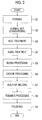
Fig. 2 is a flowchart showing an embodiment of a steam turbine vane manufacturing method. -
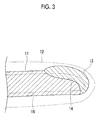
Fig. 3 is a cross-sectional view showing a steam turbine vane material. -
Fig. 4 is a flowchart showing another embodiment of the steam turbine vane manufacturing method. -
Fig. 5 is a cross-sectional view showing another steam turbine vane material. -
Fig. 6 is a flowchart showing still another embodiment of the steam turbine vane manufacturing method. - An embodiment of a steam turbine vane according to the present invention will be described below with reference to the drawings. A steam turbine vane 1 is utilized in a steam turbine and provided with a
root section 2 and anaerofoil profile section 3, as shown inFig. 1 . Theroot section 2 is mounted on a rotor of a steam turbine. Theaerofoil profile section 3 is formed in an aerofoil profile and fixed to theroot section 2. Theaerofoil profile section 3 is exposed to steam flowing through the steam turbine when theroot section 2 is mounted on the rotor of the steam turbine. - The
aerofoil profile section 3 is provided with amain body portion 5 and aprotective part 6. Themain body portion 5 is formed in a substantially aerofoil profile and formed integrally with theroot section 2, thereby being fixed to theroot section 2. Theprotective part 6 is formed of Stellite (registered trademark). Theprotective part 6 is joined to themain body portion 5 so as to form a leading edge portion of an airfoil tip of theaerofoil profile section 3. - An embodiment of a steam turbine vane manufacturing method is utilized when manufacturing the steam turbine vane 1. In the steam turbine vane manufacturing method, first, as shown in
Fig. 2 , a steam turbine vane material after forging is manufactured by forging a solid metal blank (Step S1). The steam turbine vane material after forging is formed in a predetermined shape with high accuracy by being further subjected to coining. After the coining, the steam turbine vane material after forging is formed in a predetermined shape with higher accuracy by being subjected to hot straightening (Step S2). - After the hot straightening, the steam turbine vane material after forging is subjected to solution heat treatment. After the solution heat treatment, the steam turbine vane material after forging is subjected to stabilization heat treatment (Step S3). After the heat treatment, the steam turbine vane material after forging is further subjected to aging treatment, thereby being hardened (Step S4).
- After the aging treatment, the steam turbine vane material after forging is subjected to straightening so as to be formed in a predetermined shape. After the straightening, the steam turbine vane material after forging is subjected to cutting, thereby being formed into a steam turbine vane material after rough processing (Step S5). As shown in
Fig. 3 , most of the surface formed in a steam turbine vane material after forging 12 is removed by cutting, and thus a steam turbine vane material afterrough processing 11 is smaller than the steam turbine vane material after forging 12. - The steam turbine vane material after
rough processing 11 is further subjected to cutting, whereby a protectivepart joint surface 14 is formed (Step S6). The protectivepart joint surface 14 is formed in an area corresponding to a leading edge portion of the steam turbine vane 1, of the steam turbine vane material afterrough processing 11, and formed to be concave. - In the steam turbine vane material after
rough processing 11, after the protectivepart joint surface 14 is formed, filler metal which contains Stellite (registered trademark) is buildup-welded to the protectivepart joint surface 14 by using a laser beam which is emitted from a CO2 laser. In the steam turbine vane material afterrough processing 11, a protective part build-up bead 15 is formed by the build-up welding (Step S7). For this reason, the protective part build-up bead 15 is formed of Stellite (registered trademark) and solidly joined to the protective partjoint surface 14. The protective part build-up bead 15 is formed in an area corresponding to the leading edge portion of the steam turbine vane 1, of the steam turbine vane material afterrough processing 11, and formed as a projection. - After the protective part build-
up bead 15 is formed, the steam turbine vane material afterrough processing 11 is subjected to straightening so as to be formed in a predetermined shape. After the straightening, the steam turbine vane material afterrough processing 11 is subjected to cutting, thereby being formed into a steam turbine vane material after finishing processing 16 (Step S8). The steam turbine vane material afterfinishing processing 16 is formed such that most of the surface of the steam turbine vane material afterrough processing 11 is removed and such that most of the surface of the protective part build-up bead 15 is removed. For this reason, the steam turbine vane material after finishingprocessing 16 is smaller than the steam turbine vane material afterrough processing 11. The steam turbine vane material after finishingprocessing 16 is subjected to polishing, thereby being formed into the steam turbine vane 1 (Step S9). The steam turbine vane 1 is manufactured in this manner, whereby a portion of the protective part build-up bead 15 is formed into theprotective part 6. - In a comparative example of the steam turbine vane manufacturing method, the steam turbine vane 1 is manufactured by joining a Stellite plate to the protective part
joint surface 14 of the steam turbine vane material after finishingprocessing 16 by brazing. In a case of joining the Stellite plate to the protectivepart joint surface 14 by brazing, it is necessary for the protectivepart joint surface 14 to be sufficiently heated, and thus it is necessary to heat the surface on the side opposite to the protectivepart joint surface 14, of a base material. For this reason, the amount of heat which is input to the base material due to the brazing is relatively large. - In this steam turbine vane manufacturing method, the protective part build-up
bead 15 is formed by build-up welding, whereby it is not necessary to heat the surface on the side opposite to the protective partjoint surface 14, of the steam turbine vane material afterrough processing 11. For this reason, in this steam turbine vane manufacturing method, as compared to the steam turbine vane manufacturing method of the comparative example in which the steam turbine vane is manufactured by joining the Stellite plate to the protective partjoint surface 14 by brazing, it is possible to reduce the amount of heat which is input to the steam turbine vane material afterrough processing 11. As a result, in this steam turbine vane manufacturing method, as compared to the comparative example, it is possible to reduce the deformation amount of the steam turbine vane material afterrough processing 11, and thus it is possible to more appropriately manufacture the steam turbine vane 1. - The deformation amount of a relatively large base material which is deformed by build-up welding is smaller than the deformation amount of a relatively small base material which is deformed by build-up welding. For this reason, in this steam turbine vane manufacturing method, the protective part build-up
bead 15 is formed on the protective partjoint surface 14 of the steam turbine vane material afterrough processing 11, whereby the deformation amount of the base material can be reduced, as compared to a case of forming the protective part build-upbead 15 on the protective partjoint surface 14 of the steam turbine vane material after finishingprocessing 16. As a result, in this steam turbine vane manufacturing method, it is possible to more appropriately manufacture the steam turbine vane 1, as compared to another steam turbine vane manufacturing method in which build-up welding is performed on the steam turbine vane material after finishingprocessing 16. -
Fig. 4 shows another embodiment of the steam turbine vane manufacturing method according to the present invention. In the steam turbine vane manufacturing method, first, in the same manner as in the steam turbine vane manufacturing method shown inFig. 2 , a steam turbine vane material after forging is manufactured by forging a solid metal blank (Step S11) and then subjected to coining and hot straightening (Step S12). - After the hot straightening, a steam turbine vane material after forging 21 is subjected to cutting, as shown in
Fig. 5 , whereby a protective partjoint surface 22 is formed (Step S13). In the steam turbine vane material after forging 21, after the protective partjoint surface 22 is formed, the protective partjoint surface 22 is subjected to build-up welded, whereby a protective part build-upbead 23 is formed (Step S14). - After the protective part build-up
bead 23 is formed, the steam turbine vane material after forging 21 is subjected to solution heat treatment and subjected to stabilization heat treatment (Step S15). After the heat treatment, the steam turbine vane material after forging 21 is subjected to straightening so as to be formed in a predetermined shape. After the straightening, the steam turbine vane material after forging 21 is subjected to cutting, thereby being formed into a steam turbine vane material after rough processing 24 (Step S16). - The steam turbine vane material after
rough processing 24 is subjected to aging treatment (Step S17). After the aging treatment, the steam turbine vane material afterrough processing 24 is subjected to straightening so as to be formed in a predetermined shape. After the straightening, the steam turbine vane material afterrough processing 24 is subjected to cutting, thereby being formed into a steam turbine vane material after finishing processing 25 (Step S18). The steam turbine vane material after finishingprocessing 25 is subjected to polishing, thereby being formed into the steam turbine vane 1 (Step S19). The steam turbine vane 1 is manufactured in this manner, whereby a portion of the protective part build-upbead 23 is formed into theprotective part 6. - In the steam turbine vane material after forging 21 with the protective part
joint surface 22 formed therein, a portion of the surface formed by forging remains, and thus the steam turbine vane material after forging 21 is larger than the steam turbine vane material afterrough processing 11 in the above-described embodiment. For this reason, the deformation amount of the steam turbine vane material after forging 21 which is deformed by build-up welding is smaller than the deformation amount of the steam turbine vane material afterrough processing 11 which is deformed by build-up welding. In this steam turbine vane manufacturing method, as compared to the steam turbine vane manufacturing method in the above-described embodiment, it is possible to more appropriately manufacture the steam turbine vane 1. -
Fig. 6 shows still another embodiment of the steam turbine vane manufacturing method according to the present invention. In the steam turbine vane manufacturing method, first, in the same manner as in the steam turbine vane manufacturing method shown inFig. 4 , the steam turbine vane material after forging 21 is manufactured by forging a solid metal blank (Step S21) and then subjected to coining and hot straightening (Step S22), whereby the protective partjoint surface 22 is formed (Step S23). - After the protective part
joint surface 22 is formed, the steam turbine vane material after forging 21 is subjected to solution heat treatment and subjected to stabilization heat treatment (Step S24). After the heat treatment, in the steam turbine vane material after forging 21, the protective partjoint surface 22 is subjected to build-up welding, whereby the protective part build-upbead 23 is formed (Step S25). - After the protective part build-up
bead 23 is formed, the steam turbine vane material after forging 21 is subjected to aging treatment (Step S26). After the aging treatment, the steam turbine vane material after forging 21 is subjected to straightening so as to be formed in a predetermined shape. After the straightening, the steam turbine vane material after forging 21 is subjected to cutting, thereby being formed into the steam turbine vane material after rough processing 24 (Step S27). - The steam turbine vane material after
rough processing 24 is subjected to straightening so as to be formed in a predetermined shape. After the straightening, the steam turbine vane material afterrough processing 24 is subjected to cutting, thereby being formed into the steam turbine vane material after finishing processing 25 (Step S28). The steam turbine vane material after finishingprocessing 25 is subjected to polishing, thereby being formed into the steam turbine vane 1 (Step S29). The steam turbine vane 1 is manufactured in this manner, whereby a portion of the protective part build-upbead 23 is formed into theprotective part 6. - Also in this steam turbine vane manufacturing method, it is possible to appropriately manufacture the steam turbine vane 1, in the same manner as in the above-described steam turbine vane manufacturing method shown in
Fig. 4 . In general, the higher the hardness of the steam turbine vane material after forging 21, the easier the straightening for forming the steam turbine vane material after forging 21 into a predetermined shape. According to this steam turbine vane manufacturing method, the steam turbine vane material after forging 21 is subjected to aging treatment and then subjected to straightening so as to be formed in a predetermined shape, whereby the hardness of the steam turbine vane material after forging 21 immediately before it is subjected to rough processing is higher, as compared to the above-described steam turbine vane manufacturing method shown inFig. 4 . For this reason, according to this steam turbine vane manufacturing method, it is possible to more easily manufacture the steam turbine vane 1, as compared to the steam turbine vane manufacturing method shown inFig. 4 . - In addition, the
protective part 6 can be formed of a material which is different from Stellite (registered trademark). The material is a material having superior erosion resistance to a material for forming themain body portion 5, and for example, austenitic stainless steel is exemplified. Also in a steam turbine vane manufacturing method in which such a material is utilized, it is possible to more easily manufacture the steam turbine vane 1, in the same manner as in the steam turbine vane manufacturing methods in the above-described embodiments. - In addition, the laser beam which is utilized in the build-up welding can be replaced by another laser beam which is emitted from a laser oscillator which is different from the CO2 laser. As the laser oscillator, a YAG laser, a laser diode (LD), or the like is exemplified. In addition, the build-up welding can also be carried out by welding which is different from laser welding. As the welding, TIG welding is exemplified. Also in a steam turbine vane manufacturing method to which such welding is applied, it is possible to appropriately manufacture the steam turbine vane 1, in the same manner as in the steam turbine vane manufacturing methods in the above-described embodiments.
-
- 1:
- steam turbine vane
- 2:
- root section
- 3:
- aerofoil profile section
- 5:
- main body portion
- 6:
- protective part
- 11:
- steam turbine vane material after rough processing
- 12:
- steam turbine vane material after forging
- 14:
- protective part joint surface
- 15:
- protective part build-up bead
- 16:
- steam turbine vane material after finishing processing
- 21:
- steam turbine vane material after forging
- 22:
- protective part joint surface
- 23:
- protective part build-up bead
- 24:
- steam turbine vane material after rough processing
- 25:
- steam turbine vane material after finishing processing
Claims (4)
- A steam turbine vane manufacturing method comprising:a groove processing step of forming a protective part joint surface in a steam turbine vane material;a build-up welding step of forming a protective part build-up bead on the protective part joint surface by build-up welding; anda processing step of processing the steam turbine vane material into a steam turbine vane by cutting the protective part build-up bead along with the steam turbine vane material.
- The steam turbine vane manufacturing method according to Claim 1, further comprising: a forging step of manufacturing the steam turbine vane material by forging.
- The steam turbine vane manufacturing method according to Claim 1 or 2, further comprising: an aging treatment step of performing aging treatment on the steam turbine vane material along with the protective part build-up bead before the processing step is carried out.
- A steam turbine vane which is manufactured by the steam turbine vane manufacturing method according to any one of Claims 1 to 3.
Applications Claiming Priority (2)
| Application Number | Priority Date | Filing Date | Title |
|---|---|---|---|
| JP2013050087A JP6100037B2 (en) | 2013-03-13 | 2013-03-13 | Steam turbine blade manufacturing method |
| PCT/JP2014/051519 WO2014141755A1 (en) | 2013-03-13 | 2014-01-24 | Steam turbine vane manufacturing method |
Publications (3)
| Publication Number | Publication Date |
|---|---|
| EP2975225A1 true EP2975225A1 (en) | 2016-01-20 |
| EP2975225A4 EP2975225A4 (en) | 2016-10-26 |
| EP2975225B1 EP2975225B1 (en) | 2019-01-16 |
Family
ID=51536431
Family Applications (1)
| Application Number | Title | Priority Date | Filing Date |
|---|---|---|---|
| EP14764425.6A Not-in-force EP2975225B1 (en) | 2013-03-13 | 2014-01-24 | Steam turbine vane manufacturing method |
Country Status (6)
| Country | Link |
|---|---|
| US (1) | US10107113B2 (en) |
| EP (1) | EP2975225B1 (en) |
| JP (1) | JP6100037B2 (en) |
| KR (2) | KR20150103113A (en) |
| CN (1) | CN105008674B (en) |
| WO (1) | WO2014141755A1 (en) |
Families Citing this family (5)
| Publication number | Priority date | Publication date | Assignee | Title |
|---|---|---|---|---|
| CN103203543B (en) * | 2013-02-04 | 2015-03-11 | 中国航空工业集团公司北京航空制造工程研究所 | Method and device for injecting water restraint layer of laser shock processing blade |
| JP6320134B2 (en) | 2014-04-07 | 2018-05-09 | 三菱日立パワーシステムズ株式会社 | Rotor blade, method for forming erosion shield, and rotor blade manufacturing method |
| DE102014220483A1 (en) * | 2014-10-09 | 2016-04-14 | Fraunhofer-Gesellschaft zur Förderung der angewandten Forschung e.V. | Construction strategy for a crown bottom of a turbine blade and turbine blade |
| CN104439617B (en) * | 2014-10-27 | 2016-07-27 | 沈阳黎明航空发动机(集团)有限责任公司 | A kind of Turbine Sawtooth Shroud wearing layer preparation method |
| JP6746457B2 (en) * | 2016-10-07 | 2020-08-26 | 三菱日立パワーシステムズ株式会社 | Turbine blade manufacturing method |
Family Cites Families (28)
| Publication number | Priority date | Publication date | Assignee | Title |
|---|---|---|---|---|
| JPS6263101A (en) * | 1985-09-13 | 1987-03-19 | Toshiba Corp | Turbine blade |
| JPH01202389A (en) * | 1988-02-05 | 1989-08-15 | Hitachi Ltd | Method for manufacturing steam turbine long blades |
| JPH0240003A (en) * | 1988-07-29 | 1990-02-08 | Hitachi Ltd | Steam turbine blade |
| JPH0299283A (en) * | 1988-10-03 | 1990-04-11 | Toshiba Corp | Manufacture of turbine bucket |
| JP3057606B2 (en) * | 1990-07-03 | 2000-07-04 | 株式会社東芝 | Method of manufacturing turbine blade made of titanium alloy |
| DE69321298T2 (en) * | 1992-06-05 | 1999-04-08 | Gec Alsthom Electromecanique S.A., Paris | Process for producing an insert on a shaped body to be coated made of steel or titanium alloy |
| US5351395A (en) * | 1992-12-30 | 1994-10-04 | General Electric Company | Process for producing turbine bucket with water droplet erosion protection |
| DE4310896C1 (en) * | 1993-04-02 | 1994-03-24 | Thyssen Industrie | Mfr. process for wear resistant edges on turbine blades, pref. steam turbine blades of chrome steels and/or titanium@ base alloys - by application of a powder layer by plasma spraying or encapsulation, followed by hot isostatic pressing |
| JPH07158402A (en) * | 1993-12-10 | 1995-06-20 | Mitsubishi Heavy Ind Ltd | Turbomachine blades |
| DE69529178T2 (en) * | 1995-09-13 | 2003-10-02 | Boehler Schmiedetechnik Ges.M.B.H. & Co. Kg, Kapfenberg | METHOD FOR PRODUCING A TITANIUM ALLOY TURBINE BLADE AND TITANIUM ALLOY TURBINE BLADE |
| JP2003226943A (en) | 2002-02-06 | 2003-08-15 | Toshiba Corp | High-strength, high-corrosion-resistant steel, method for producing the same, and geothermal turbine blade |
| FR2866821B1 (en) * | 2004-02-27 | 2006-06-09 | Snecma Moteurs | PRESS FOR MAINTAINING AND PRESSING A PIECE |
| JP2006016671A (en) * | 2004-07-02 | 2006-01-19 | Hitachi Ltd | Ni-based alloy member and manufacturing method thereof, turbine engine component, welding material and manufacturing method thereof |
| US20060067830A1 (en) * | 2004-09-29 | 2006-03-30 | Wen Guo | Method to restore an airfoil leading edge |
| GB0504576D0 (en) * | 2005-03-05 | 2005-04-13 | Alstom Technology Ltd | Turbine blades and methods for depositing an erosion resistant coating on the same |
| JP4546318B2 (en) | 2005-04-15 | 2010-09-15 | 株式会社日立製作所 | Ni-based alloy member and manufacturing method thereof, turbine engine component, welding material and manufacturing method thereof |
| US7967924B2 (en) * | 2005-05-17 | 2011-06-28 | General Electric Company | Method for making a compositionally graded gas turbine disk |
| JP4901413B2 (en) | 2006-10-13 | 2012-03-21 | 株式会社東芝 | Erosion prevention method and member with erosion prevention part |
| US20080181808A1 (en) | 2007-01-31 | 2008-07-31 | Samuel Vinod Thamboo | Methods and articles relating to high strength erosion resistant titanium alloy |
| EP2072176A1 (en) | 2007-12-21 | 2009-06-24 | Sulzer Markets and Technology AG | Method of manufacturing an erosion protection steel layer using laser buildup; Component with such an erosion protection steel layer |
| JP4991669B2 (en) | 2008-09-30 | 2012-08-01 | 株式会社日立製作所 | Turbine blade and steam turbine |
| GB0906850D0 (en) * | 2009-04-22 | 2009-06-03 | Rolls Royce Plc | Method of manufacturing an aerofoil |
| JP5854284B2 (en) * | 2010-09-27 | 2016-02-09 | 日立金属株式会社 | Blade material manufacturing method and blade material manufacturing apparatus |
| JP5785376B2 (en) | 2010-10-19 | 2015-09-30 | 株式会社東芝 | Overlay welding method |
| JP5409708B2 (en) * | 2011-06-16 | 2014-02-05 | 株式会社日立製作所 | Precipitation hardening type martensitic stainless steel and steam turbine long blades using the same |
| US9291062B2 (en) * | 2012-09-07 | 2016-03-22 | General Electric Company | Methods of forming blades and method for rendering a blade resistant to erosion |
| CN104718348B (en) * | 2012-09-21 | 2016-09-28 | 三菱日立电力系统株式会社 | Welding method of corrosion-resistant metal material and turbine blade |
| JP6178703B2 (en) * | 2013-11-13 | 2017-08-09 | 三菱日立パワーシステムズ株式会社 | Method for manufacturing steam turbine rotor blade with anticorrosion piece |
-
2013
- 2013-03-13 JP JP2013050087A patent/JP6100037B2/en not_active Expired - Fee Related
-
2014
- 2014-01-24 CN CN201480006374.2A patent/CN105008674B/en not_active Expired - Fee Related
- 2014-01-24 EP EP14764425.6A patent/EP2975225B1/en not_active Not-in-force
- 2014-01-24 US US14/762,341 patent/US10107113B2/en not_active Expired - Fee Related
- 2014-01-24 WO PCT/JP2014/051519 patent/WO2014141755A1/en not_active Ceased
- 2014-01-24 KR KR1020157020193A patent/KR20150103113A/en not_active Ceased
- 2014-01-24 KR KR1020177029829A patent/KR101905355B1/en not_active Expired - Fee Related
Also Published As
| Publication number | Publication date |
|---|---|
| WO2014141755A1 (en) | 2014-09-18 |
| JP6100037B2 (en) | 2017-03-22 |
| KR101905355B1 (en) | 2018-10-05 |
| US20150377043A1 (en) | 2015-12-31 |
| KR20170118978A (en) | 2017-10-25 |
| US10107113B2 (en) | 2018-10-23 |
| CN105008674A (en) | 2015-10-28 |
| JP2014173582A (en) | 2014-09-22 |
| EP2975225B1 (en) | 2019-01-16 |
| EP2975225A4 (en) | 2016-10-26 |
| CN105008674B (en) | 2018-01-12 |
| KR20150103113A (en) | 2015-09-09 |
Similar Documents
| Publication | Publication Date | Title |
|---|---|---|
| US10107113B2 (en) | Steam turbine vane manufacturing method | |
| RU2649105C2 (en) | Method for friction welding a blade onto a turbine engine rotor disc and corresponding integral blade disc | |
| US20140072715A1 (en) | Methods of forming blades and method for rendering a blade resistant to erosion | |
| US20150104323A1 (en) | Method for creating a metal reinforcement with insert for protecting a leading edge made of composite | |
| EP0605152A1 (en) | Process for producing turbine bucket with water droplet erosion protection and realted product | |
| US9500080B2 (en) | Method of replacing damaged aerofoil | |
| JP6562284B2 (en) | Hot forging die | |
| US20110058934A1 (en) | Cooled Turbine Airfoil Fabricated From Sheet Material | |
| JP5535799B2 (en) | Repair method of metal parts and repaired metal parts | |
| JPH09192880A (en) | Method for manufacturing blade of αβ titanium having metastable β titanium insert and blade manufactured by the method | |
| US1829179A (en) | Method of making turbine blades | |
| US20220063028A1 (en) | Method for producing a metal reinforcement for a turbomachine blade | |
| US11724322B2 (en) | Saw blade and method of manufacturing the same | |
| WO2011052903A3 (en) | Stainless steel joining method | |
| RU2019128112A (en) | METHOD FOR PRODUCING PARTS FROM ALLOYS OF METALS OF COMPLEX SHAPE | |
| EP2644310A1 (en) | A method of joining at least two components, a method for rendering a component resistant to erosion, and a turbine blade | |
| US7204677B2 (en) | Countering laser shock peening induced blade twist | |
| US9816382B2 (en) | Turbomachine blade and relative production method | |
| EP3281720B1 (en) | Hot forging die and hot forging method | |
| Richter | Laser material processing in the aero engine industry. Established, cutting-edge and emerging applications | |
| JPH0424525B2 (en) | ||
| JP2849496B2 (en) | Manufacturing method of high and low pressure integrated rotor | |
| JP2016209908A (en) | Mold for hot forging | |
| WO2004065051A1 (en) | Turbine refurbishment |
Legal Events
| Date | Code | Title | Description |
|---|---|---|---|
| PUAI | Public reference made under article 153(3) epc to a published international application that has entered the european phase |
Free format text: ORIGINAL CODE: 0009012 |
|
| 17P | Request for examination filed |
Effective date: 20150727 |
|
| AK | Designated contracting states |
Kind code of ref document: A1 Designated state(s): AL AT BE BG CH CY CZ DE DK EE ES FI FR GB GR HR HU IE IS IT LI LT LU LV MC MK MT NL NO PL PT RO RS SE SI SK SM TR |
|
| AX | Request for extension of the european patent |
Extension state: BA ME |
|
| DAX | Request for extension of the european patent (deleted) | ||
| A4 | Supplementary search report drawn up and despatched |
Effective date: 20160923 |
|
| RIC1 | Information provided on ipc code assigned before grant |
Ipc: B23K 31/00 20060101ALI20160919BHEP Ipc: B23K 9/00 20060101ALI20160919BHEP Ipc: F01D 25/00 20060101AFI20160919BHEP Ipc: B23K 26/34 20140101ALI20160919BHEP Ipc: B23K 26/21 20140101ALI20160919BHEP Ipc: F01D 5/28 20060101ALI20160919BHEP Ipc: B23K 9/04 20060101ALI20160919BHEP |
|
| GRAP | Despatch of communication of intention to grant a patent |
Free format text: ORIGINAL CODE: EPIDOSNIGR1 |
|
| STAA | Information on the status of an ep patent application or granted ep patent |
Free format text: STATUS: GRANT OF PATENT IS INTENDED |
|
| INTG | Intention to grant announced |
Effective date: 20180919 |
|
| GRAS | Grant fee paid |
Free format text: ORIGINAL CODE: EPIDOSNIGR3 |
|
| GRAA | (expected) grant |
Free format text: ORIGINAL CODE: 0009210 |
|
| STAA | Information on the status of an ep patent application or granted ep patent |
Free format text: STATUS: THE PATENT HAS BEEN GRANTED |
|
| AK | Designated contracting states |
Kind code of ref document: B1 Designated state(s): AL AT BE BG CH CY CZ DE DK EE ES FI FR GB GR HR HU IE IS IT LI LT LU LV MC MK MT NL NO PL PT RO RS SE SI SK SM TR |
|
| REG | Reference to a national code |
Ref country code: GB Ref legal event code: FG4D |
|
| REG | Reference to a national code |
Ref country code: CH Ref legal event code: EP |
|
| REG | Reference to a national code |
Ref country code: IE Ref legal event code: FG4D |
|
| REG | Reference to a national code |
Ref country code: DE Ref legal event code: R096 Ref document number: 602014040030 Country of ref document: DE |
|
| REG | Reference to a national code |
Ref country code: AT Ref legal event code: REF Ref document number: 1089854 Country of ref document: AT Kind code of ref document: T Effective date: 20190215 |
|
| REG | Reference to a national code |
Ref country code: NL Ref legal event code: MP Effective date: 20190116 |
|
| REG | Reference to a national code |
Ref country code: LT Ref legal event code: MG4D |
|
| PG25 | Lapsed in a contracting state [announced via postgrant information from national office to epo] |
Ref country code: NL Free format text: LAPSE BECAUSE OF FAILURE TO SUBMIT A TRANSLATION OF THE DESCRIPTION OR TO PAY THE FEE WITHIN THE PRESCRIBED TIME-LIMIT Effective date: 20190116 |
|
| REG | Reference to a national code |
Ref country code: AT Ref legal event code: MK05 Ref document number: 1089854 Country of ref document: AT Kind code of ref document: T Effective date: 20190116 |
|
| PG25 | Lapsed in a contracting state [announced via postgrant information from national office to epo] |
Ref country code: PT Free format text: LAPSE BECAUSE OF FAILURE TO SUBMIT A TRANSLATION OF THE DESCRIPTION OR TO PAY THE FEE WITHIN THE PRESCRIBED TIME-LIMIT Effective date: 20190516 Ref country code: SE Free format text: LAPSE BECAUSE OF FAILURE TO SUBMIT A TRANSLATION OF THE DESCRIPTION OR TO PAY THE FEE WITHIN THE PRESCRIBED TIME-LIMIT Effective date: 20190116 Ref country code: ES Free format text: LAPSE BECAUSE OF FAILURE TO SUBMIT A TRANSLATION OF THE DESCRIPTION OR TO PAY THE FEE WITHIN THE PRESCRIBED TIME-LIMIT Effective date: 20190116 Ref country code: FI Free format text: LAPSE BECAUSE OF FAILURE TO SUBMIT A TRANSLATION OF THE DESCRIPTION OR TO PAY THE FEE WITHIN THE PRESCRIBED TIME-LIMIT Effective date: 20190116 Ref country code: LT Free format text: LAPSE BECAUSE OF FAILURE TO SUBMIT A TRANSLATION OF THE DESCRIPTION OR TO PAY THE FEE WITHIN THE PRESCRIBED TIME-LIMIT Effective date: 20190116 Ref country code: PL Free format text: LAPSE BECAUSE OF FAILURE TO SUBMIT A TRANSLATION OF THE DESCRIPTION OR TO PAY THE FEE WITHIN THE PRESCRIBED TIME-LIMIT Effective date: 20190116 Ref country code: NO Free format text: LAPSE BECAUSE OF FAILURE TO SUBMIT A TRANSLATION OF THE DESCRIPTION OR TO PAY THE FEE WITHIN THE PRESCRIBED TIME-LIMIT Effective date: 20190416 |
|
| PG25 | Lapsed in a contracting state [announced via postgrant information from national office to epo] |
Ref country code: IS Free format text: LAPSE BECAUSE OF FAILURE TO SUBMIT A TRANSLATION OF THE DESCRIPTION OR TO PAY THE FEE WITHIN THE PRESCRIBED TIME-LIMIT Effective date: 20190516 Ref country code: BG Free format text: LAPSE BECAUSE OF FAILURE TO SUBMIT A TRANSLATION OF THE DESCRIPTION OR TO PAY THE FEE WITHIN THE PRESCRIBED TIME-LIMIT Effective date: 20190416 Ref country code: HR Free format text: LAPSE BECAUSE OF FAILURE TO SUBMIT A TRANSLATION OF THE DESCRIPTION OR TO PAY THE FEE WITHIN THE PRESCRIBED TIME-LIMIT Effective date: 20190116 Ref country code: GR Free format text: LAPSE BECAUSE OF FAILURE TO SUBMIT A TRANSLATION OF THE DESCRIPTION OR TO PAY THE FEE WITHIN THE PRESCRIBED TIME-LIMIT Effective date: 20190417 Ref country code: LV Free format text: LAPSE BECAUSE OF FAILURE TO SUBMIT A TRANSLATION OF THE DESCRIPTION OR TO PAY THE FEE WITHIN THE PRESCRIBED TIME-LIMIT Effective date: 20190116 Ref country code: RS Free format text: LAPSE BECAUSE OF FAILURE TO SUBMIT A TRANSLATION OF THE DESCRIPTION OR TO PAY THE FEE WITHIN THE PRESCRIBED TIME-LIMIT Effective date: 20190116 |
|
| REG | Reference to a national code |
Ref country code: CH Ref legal event code: PL |
|
| PG25 | Lapsed in a contracting state [announced via postgrant information from national office to epo] |
Ref country code: LU Free format text: LAPSE BECAUSE OF NON-PAYMENT OF DUE FEES Effective date: 20190124 |
|
| REG | Reference to a national code |
Ref country code: BE Ref legal event code: MM Effective date: 20190131 Ref country code: DE Ref legal event code: R097 Ref document number: 602014040030 Country of ref document: DE |
|
| REG | Reference to a national code |
Ref country code: IE Ref legal event code: MM4A |
|
| PG25 | Lapsed in a contracting state [announced via postgrant information from national office to epo] |
Ref country code: CZ Free format text: LAPSE BECAUSE OF FAILURE TO SUBMIT A TRANSLATION OF THE DESCRIPTION OR TO PAY THE FEE WITHIN THE PRESCRIBED TIME-LIMIT Effective date: 20190116 Ref country code: IT Free format text: LAPSE BECAUSE OF FAILURE TO SUBMIT A TRANSLATION OF THE DESCRIPTION OR TO PAY THE FEE WITHIN THE PRESCRIBED TIME-LIMIT Effective date: 20190116 Ref country code: RO Free format text: LAPSE BECAUSE OF FAILURE TO SUBMIT A TRANSLATION OF THE DESCRIPTION OR TO PAY THE FEE WITHIN THE PRESCRIBED TIME-LIMIT Effective date: 20190116 Ref country code: SK Free format text: LAPSE BECAUSE OF FAILURE TO SUBMIT A TRANSLATION OF THE DESCRIPTION OR TO PAY THE FEE WITHIN THE PRESCRIBED TIME-LIMIT Effective date: 20190116 Ref country code: DK Free format text: LAPSE BECAUSE OF FAILURE TO SUBMIT A TRANSLATION OF THE DESCRIPTION OR TO PAY THE FEE WITHIN THE PRESCRIBED TIME-LIMIT Effective date: 20190116 Ref country code: EE Free format text: LAPSE BECAUSE OF FAILURE TO SUBMIT A TRANSLATION OF THE DESCRIPTION OR TO PAY THE FEE WITHIN THE PRESCRIBED TIME-LIMIT Effective date: 20190116 Ref country code: AT Free format text: LAPSE BECAUSE OF FAILURE TO SUBMIT A TRANSLATION OF THE DESCRIPTION OR TO PAY THE FEE WITHIN THE PRESCRIBED TIME-LIMIT Effective date: 20190116 Ref country code: MC Free format text: LAPSE BECAUSE OF FAILURE TO SUBMIT A TRANSLATION OF THE DESCRIPTION OR TO PAY THE FEE WITHIN THE PRESCRIBED TIME-LIMIT Effective date: 20190116 Ref country code: AL Free format text: LAPSE BECAUSE OF FAILURE TO SUBMIT A TRANSLATION OF THE DESCRIPTION OR TO PAY THE FEE WITHIN THE PRESCRIBED TIME-LIMIT Effective date: 20190116 |
|
| PLBE | No opposition filed within time limit |
Free format text: ORIGINAL CODE: 0009261 |
|
| STAA | Information on the status of an ep patent application or granted ep patent |
Free format text: STATUS: NO OPPOSITION FILED WITHIN TIME LIMIT |
|
| PG25 | Lapsed in a contracting state [announced via postgrant information from national office to epo] |
Ref country code: BE Free format text: LAPSE BECAUSE OF NON-PAYMENT OF DUE FEES Effective date: 20190131 Ref country code: SM Free format text: LAPSE BECAUSE OF FAILURE TO SUBMIT A TRANSLATION OF THE DESCRIPTION OR TO PAY THE FEE WITHIN THE PRESCRIBED TIME-LIMIT Effective date: 20190116 |
|
| 26N | No opposition filed |
Effective date: 20191017 |
|
| GBPC | Gb: european patent ceased through non-payment of renewal fee |
Effective date: 20190416 |
|
| PG25 | Lapsed in a contracting state [announced via postgrant information from national office to epo] |
Ref country code: LI Free format text: LAPSE BECAUSE OF NON-PAYMENT OF DUE FEES Effective date: 20190131 Ref country code: CH Free format text: LAPSE BECAUSE OF NON-PAYMENT OF DUE FEES Effective date: 20190131 |
|
| PG25 | Lapsed in a contracting state [announced via postgrant information from national office to epo] |
Ref country code: IE Free format text: LAPSE BECAUSE OF NON-PAYMENT OF DUE FEES Effective date: 20190124 Ref country code: GB Free format text: LAPSE BECAUSE OF NON-PAYMENT OF DUE FEES Effective date: 20190416 |
|
| PG25 | Lapsed in a contracting state [announced via postgrant information from national office to epo] |
Ref country code: FR Free format text: LAPSE BECAUSE OF NON-PAYMENT OF DUE FEES Effective date: 20190316 Ref country code: SI Free format text: LAPSE BECAUSE OF FAILURE TO SUBMIT A TRANSLATION OF THE DESCRIPTION OR TO PAY THE FEE WITHIN THE PRESCRIBED TIME-LIMIT Effective date: 20190116 |
|
| PG25 | Lapsed in a contracting state [announced via postgrant information from national office to epo] |
Ref country code: TR Free format text: LAPSE BECAUSE OF FAILURE TO SUBMIT A TRANSLATION OF THE DESCRIPTION OR TO PAY THE FEE WITHIN THE PRESCRIBED TIME-LIMIT Effective date: 20190116 |
|
| PG25 | Lapsed in a contracting state [announced via postgrant information from national office to epo] |
Ref country code: MT Free format text: LAPSE BECAUSE OF NON-PAYMENT OF DUE FEES Effective date: 20190124 |
|
| PG25 | Lapsed in a contracting state [announced via postgrant information from national office to epo] |
Ref country code: CY Free format text: LAPSE BECAUSE OF FAILURE TO SUBMIT A TRANSLATION OF THE DESCRIPTION OR TO PAY THE FEE WITHIN THE PRESCRIBED TIME-LIMIT Effective date: 20190116 |
|
| PGFP | Annual fee paid to national office [announced via postgrant information from national office to epo] |
Ref country code: DE Payment date: 20210112 Year of fee payment: 8 |
|
| PG25 | Lapsed in a contracting state [announced via postgrant information from national office to epo] |
Ref country code: HU Free format text: LAPSE BECAUSE OF FAILURE TO SUBMIT A TRANSLATION OF THE DESCRIPTION OR TO PAY THE FEE WITHIN THE PRESCRIBED TIME-LIMIT; INVALID AB INITIO Effective date: 20140124 |
|
| PG25 | Lapsed in a contracting state [announced via postgrant information from national office to epo] |
Ref country code: MK Free format text: LAPSE BECAUSE OF FAILURE TO SUBMIT A TRANSLATION OF THE DESCRIPTION OR TO PAY THE FEE WITHIN THE PRESCRIBED TIME-LIMIT Effective date: 20190116 |
|
| REG | Reference to a national code |
Ref country code: DE Ref legal event code: R119 Ref document number: 602014040030 Country of ref document: DE |
|
| PG25 | Lapsed in a contracting state [announced via postgrant information from national office to epo] |
Ref country code: DE Free format text: LAPSE BECAUSE OF NON-PAYMENT OF DUE FEES Effective date: 20220802 |