EP2974856A1 - Method and device for opening spout attachment portion of a bag - Google Patents
Method and device for opening spout attachment portion of a bag Download PDFInfo
- Publication number
- EP2974856A1 EP2974856A1 EP15002112.9A EP15002112A EP2974856A1 EP 2974856 A1 EP2974856 A1 EP 2974856A1 EP 15002112 A EP15002112 A EP 15002112A EP 2974856 A1 EP2974856 A1 EP 2974856A1
- Authority
- EP
- European Patent Office
- Prior art keywords
- bag
- spout
- attachment portion
- pair
- spout attachment
- Prior art date
- Legal status (The legal status is an assumption and is not a legal conclusion. Google has not performed a legal analysis and makes no representation as to the accuracy of the status listed.)
- Granted
Links
Images




Classifications
-
- B—PERFORMING OPERATIONS; TRANSPORTING
- B65—CONVEYING; PACKING; STORING; HANDLING THIN OR FILAMENTARY MATERIAL
- B65B—MACHINES, APPARATUS OR DEVICES FOR, OR METHODS OF, PACKAGING ARTICLES OR MATERIALS; UNPACKING
- B65B43/00—Forming, feeding, opening or setting-up containers or receptacles in association with packaging
- B65B43/26—Opening or distending bags; Opening, erecting, or setting-up boxes, cartons, or carton blanks
-
- B—PERFORMING OPERATIONS; TRANSPORTING
- B65—CONVEYING; PACKING; STORING; HANDLING THIN OR FILAMENTARY MATERIAL
- B65B—MACHINES, APPARATUS OR DEVICES FOR, OR METHODS OF, PACKAGING ARTICLES OR MATERIALS; UNPACKING
- B65B43/00—Forming, feeding, opening or setting-up containers or receptacles in association with packaging
- B65B43/26—Opening or distending bags; Opening, erecting, or setting-up boxes, cartons, or carton blanks
- B65B43/34—Opening or distending bags; Opening, erecting, or setting-up boxes, cartons, or carton blanks by internal pressure
- B65B43/36—Opening or distending bags; Opening, erecting, or setting-up boxes, cartons, or carton blanks by internal pressure applied pneumatically
-
- B—PERFORMING OPERATIONS; TRANSPORTING
- B31—MAKING ARTICLES OF PAPER, CARDBOARD OR MATERIAL WORKED IN A MANNER ANALOGOUS TO PAPER; WORKING PAPER, CARDBOARD OR MATERIAL WORKED IN A MANNER ANALOGOUS TO PAPER
- B31B—MAKING CONTAINERS OF PAPER, CARDBOARD OR MATERIAL WORKED IN A MANNER ANALOGOUS TO PAPER
- B31B70/00—Making flexible containers, e.g. envelopes or bags
- B31B70/74—Auxiliary operations
- B31B70/81—Forming or attaching accessories, e.g. opening devices, closures or tear strings
- B31B70/84—Forming or attaching means for filling or dispensing contents, e.g. valves or spouts
- B31B70/844—Applying rigid valves, spouts, or filling tubes
-
- B—PERFORMING OPERATIONS; TRANSPORTING
- B31—MAKING ARTICLES OF PAPER, CARDBOARD OR MATERIAL WORKED IN A MANNER ANALOGOUS TO PAPER; WORKING PAPER, CARDBOARD OR MATERIAL WORKED IN A MANNER ANALOGOUS TO PAPER
- B31B—MAKING CONTAINERS OF PAPER, CARDBOARD OR MATERIAL WORKED IN A MANNER ANALOGOUS TO PAPER
- B31B70/00—Making flexible containers, e.g. envelopes or bags
- B31B70/003—Opening or distending bags
-
- B—PERFORMING OPERATIONS; TRANSPORTING
- B65—CONVEYING; PACKING; STORING; HANDLING THIN OR FILAMENTARY MATERIAL
- B65B—MACHINES, APPARATUS OR DEVICES FOR, OR METHODS OF, PACKAGING ARTICLES OR MATERIALS; UNPACKING
- B65B43/00—Forming, feeding, opening or setting-up containers or receptacles in association with packaging
- B65B43/26—Opening or distending bags; Opening, erecting, or setting-up boxes, cartons, or carton blanks
- B65B43/30—Opening or distending bags; Opening, erecting, or setting-up boxes, cartons, or carton blanks by grippers engaging opposed walls, e.g. suction-operated
-
- B—PERFORMING OPERATIONS; TRANSPORTING
- B65—CONVEYING; PACKING; STORING; HANDLING THIN OR FILAMENTARY MATERIAL
- B65B—MACHINES, APPARATUS OR DEVICES FOR, OR METHODS OF, PACKAGING ARTICLES OR MATERIALS; UNPACKING
- B65B43/00—Forming, feeding, opening or setting-up containers or receptacles in association with packaging
- B65B43/26—Opening or distending bags; Opening, erecting, or setting-up boxes, cartons, or carton blanks
- B65B43/34—Opening or distending bags; Opening, erecting, or setting-up boxes, cartons, or carton blanks by internal pressure
-
- B—PERFORMING OPERATIONS; TRANSPORTING
- B65—CONVEYING; PACKING; STORING; HANDLING THIN OR FILAMENTARY MATERIAL
- B65D—CONTAINERS FOR STORAGE OR TRANSPORT OF ARTICLES OR MATERIALS, e.g. BAGS, BARRELS, BOTTLES, BOXES, CANS, CARTONS, CRATES, DRUMS, JARS, TANKS, HOPPERS, FORWARDING CONTAINERS; ACCESSORIES, CLOSURES, OR FITTINGS THEREFOR; PACKAGING ELEMENTS; PACKAGES
- B65D33/00—Details of, or accessories for, sacks or bags
- B65D33/16—End- or aperture-closing arrangements or devices
Definitions
- the present invention relates to a method and device for opening a spout attachment portion formed at the top end of a bag and more particularly to a method and device for opening a spout attachment portion formed by cutting off a corner that is at the top edge and one side edge of a bag.
- the present invention is applicable to, for example, an apparatus that manufactures bags that have spouts.
- Patent Reference 1 discloses how a bag that is equipped with a spout is manufactured.
- a pair of left and right grippers clamp or hold both sides of a spout attachment portion of each one of bags in which the spout attachment portion has been formed by cutting off a corner of the top edge and one side edge of the bag, the bag is hung down so that the spout attachment portion is substantially horizontal, and the thus hung down bags are intermittently conveyed along a specific conveyance path; and at various stop positions along the conveyance path, an opening step, in which the spout attachment portion is opened, a spout insertion and temporary sealing step, in which a spout is inserted into the opened spout attachment portion and then temporarily sealed, and a final sealing step, in which the spout is finally sealed to the spout attachment portion, are performed.
- Patent Reference 1 The bag disclosed in Patent Reference 1 is one that is entirely sealed including the top edge, except for the spout attachment portion.
- Patent Reference 1 describes that the bag is filled with its contents through the spout attachment portion, and this filling is done after opening up the spout attachment portion and before attaching the spout to the spout attachment portion.
- Patent Reference 2 is one in which a spout attachment portion is formed by cutting off a corner that is at the top edge and one side edge of a bag, but neither the spout attachment portion nor the top edge is sealed.
- Patent Reference 2 discloses that after a spout is attached to the spout attachment portion, the top edge (an opening used for filling) of the bag is opened up, and then the bag is filled with a liquid through this opening in the top edge.
- the bag surfaces near the spout attachment portion be suction-held by a pair of opening suction cups, the suctions cups be then retracted to open up the spout attachment portion, and then using a gas blowing member (see Japanese Patent Application Laid-Open (Kokai) No. 2002-128025 , for example) a gas is blown into the bag through the opened spout attachment portion, thus inflating the bag.
- a gas blowing member see Japanese Patent Application Laid-Open (Kokai) No. 2002-128025 , for example
- a bag 1 has a corner-cut spout attachment portion 2; and side edges 3 and 4 and a bottom edge 5 are sealed, and the spout attachment portion 2 and the top edge 6 are not sealed.
- left and right pairs of grippers 7 clamp or hold the side edge 3 and the top edge 6 on both sides of the spout attachment portion 2, and the bag 1 is allowed to be hung down so that the spout attachment portion 2 is made horizontal.
- the grippers 7 are the same as the left and right pairs of grippers disclosed in Patent Reference 1 in that they are moved intermittently along a specific conveyance path and intermittently convey the clamped bag 1 along a specific conveyance path.
- a pair of opening suction cups 8 suction-hold the films on both sides of the bag 1 at a position slightly under the spout attachment portion 2, and then they are retracted (or moved away from each other), thus opening the spout attachment portion 2.
- the grippers 7 are moved closer to each other so as not to hinder the opening of the spout attachment portion 2.
- a gas blowing member 9 disposed above the bag 1 is moved up and down; and when the spout attachment portion 2 is opened, the gas blowing member 9 is descended, the lower end of its head 9a is brought into the opening of the spout attachment portion 2 so as to block off the spout attachment portion 2 substantially completely, and then a pressurized gas is blown into the bag 1.
- the reference numeral 11 is a gas channel formed in the gas blowing member 9, one end of this gas channel opens to the lower end of the head 9a (the pressurized gas blow hole), and the other end of which is connected to a pressurized gas supply 12.
- the reference numeral 13 is an elevator member linked to the gas blowing member 9, and it is moved up and down by an elevator drive source (not shown).
- the bag 1 Since the bag 1 is not sealed at the top edge 6, as seen from FIG. 10 , when pressurized gas is blown down from the gas blowing member 9, the unclosed top edge 6 becomes an escape path for the pressurized gas, the pressurized gas freely flows out of the bag (see the white arrows in FIG. 10 ), the gas does not extend throughout the interior of the bag 1, and the center region 14 of the bag 1 under the spout attachment portion 2 (the region surrounded by the two-dot chain line) is particularly difficult to inflate.
- the region 14 after the opening suction cups 8 are separated from the bag surface, will return to its original closed (or flat) state under the restoration force of the films of the bag 1, which results in a narrowing, deformation, etc., of the opening of the spout attachment portion 2, which means that the opening shape of the spout attachment portion 2 tends to be unstable.
- the above-described restoration force is not exerted symmetrically on both ends of the spout attachment portion 2, and the opening shape of the spout attachment portion 2 tends to be even less stable.
- an object of the present invention to provide a method and device for opening a spout attachment portion formed at top end of a bag that allows a stable opening shape to be obtained even for a bag whose top edge is not sealed, and this method and device is typically employed when left and right pairs of grippers clamp both sides of a spout attachment portion of a bag in which the spout attachment portion is formed by cutting off the corner of the top edge and one of the side edges of the bag, and the bag is conveyed along a specific conveyance path while being hung down, so that on this conveyance path the spout attachment portion is kept substantially horizontal and the spout attachment portion is kept opened.
- the present invention relates to an improvement in a method for opening a spout attachment portion in which left and right pairs of grippers clamp or hold both sides of a spout attachment portion of a bag in which this spout attachment portion is formed by cutting off the corner of the top edge and one of the side edges of the bag, the bag is conveyed along a specific conveyance path while being hung down so that the spout attachment portion is substantially horizontal, and in the course of this conveyance the films on both sides of the spout attachment portion are suction-held by a pair of suction cups, and then the suction cups are moved apart to open up the spout attachment portion, after which a gas is blown into the bag by a gas blowing member to inflate the bag; and in this method, according to the present invention, the bag is one in which the top edge of the bag is not sealed, and when the gas is blown into the bag by the gas blowing member, a position under the grippers on the top edge side of the bag is clampe
- slippage occurs between the films of the bag and the clamping faces of the clamping members when the bag is inflated.
- the device for opening a spout attachment portion of a bag is to carry out the above-described opening method, and it provides such a characteristic configuration as follows:
- the clamping member is provided so that when it opens it is retracted from the conveyance path of the bag.
- the left and right pairs of clamping members are provided so that when they open both are retracted from the conveyance path of the bag.
- the left and right pairs of clamping members are provided so that when they open both are retracted from the conveyance path of the bag.
- the apparatus for manufacturing a bag equipped with a spout according to the present invention is to apply the above-described opening device to a known apparatus for manufacturing a bag that is equipped with a spout.
- a known apparatus for manufacturing a bag equipped with a spout comprises a bag conveyance device provided with a plurality of left and right pairs of grippers that are disposed along a specific conveyance path and moved intermittently along the conveyance path, with the spacing between each other being increased or decreased along the conveyance path, a bag supply device that is disposed near a bag supply position, which is a stop position on the conveyance path, and that supplies empty bags in a substantially vertical orientation to the grippers, an opening device that is installed near an opening position, which is a stop position on the conveyance path, and that opens the spout attachment portion formed in the bag, a spout insertion and temporary sealing device that is installed near a spout insertion and temporary sealing position, which is a stop position on the conveyance path, that has
- a corner cutting position for the bag is set, as a stop position on the conveyance path, between the bag supply position and the opening position.
- a corner cutting device that forms the spout attachment portion by cutting off the corner of a bag is installed near this corner cutting position.
- the spout attachment portion opening step the spout attachment portion is opened by the suction of the pair of suction cups, and pressurized gas is then blown into the bag to inflate the bag, and when the gas is thus blown into the bag, the bag is fully inflated with the pressurized gas even if the bag is of the type that the top edge is not sealed, and the bag is able to have a stable opening shape.
- FIGS. 1 to 9B The method and device for supplying bags equipped with spouts according to the present invention will be described below with reference to FIGS. 1 to 9B .
- FIGS. 1 to 9B those members and components that are substantially the same as those in FIG. 10 are numbered with the same reference numbers.
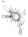
- the rotary type apparatus for manufacturing bags equipped with spouts (spout attachment machine) shown in FIG. 1 includes a bag conveyance device in which a plurality of left and right pairs of grippers 7 are provided around a table 10 that rotates intermittently.
- the grippers 7 are moved intermittently along a circular conveyance path; and while the grippers are thus being moved, the bags clamped or held by the grippers are intermittently conveyed along the circular conveyance path.
- the grippers 7 are moved to come closer to each other and moved away from each other at a specific timing while being moved along the conveyance path.
- the shown rotary apparatus for manufacturing bags each equipped with a spout is what is known as a W type (twin line) apparatus, and thus two pairs of grippers 7 form one set, and two sets of pairs of grippers are provided at a regular spacing along the conveyance path; and various steps for attaching spouts simultaneously to two bags clamped by two pairs of grippers 7 are carried out successively.
- W type twin line
- a bag supply device 15 is disposed near a stop position I (bag supply step position) on the conveyance path.
- the bag supply device 15 is basically the same as the bag supply device illustrated in Figure 1 of Patent Reference 1 (that comprises an empty bag storage device (12), a bag takeout device (13), a first supply device (28), and a second supply device (29)).
- a bag 1A (a square bag with its corner not has been cut) is positioned in a substantially horizontal orientation at the distal end of the bag storage device, and it is taken up and put in a substantially vertical orientation.
- the bag 1 A is then rotated by a specific angle along the bag plane (side surfaces of the bag) and is moved a specific distance along the bag plane to be supplied to the grippers 7.
- the angle ⁇ by which the bag 1A is rotated (see (a) in FIG. 2 ) is determined in advance based on the inclination angle of the spout attachment portion 2 formed in the bag.
- the grippers 7 clamp or hold, at a position that is slightly away from the corner distal end, the top edge 6 and the side edge 3 (see FIG. 10 ).
- the bag supply device 15 supplies two bags 1A at a time.
- a corner cutting device 16 is disposed near a stop position II (comer cutting step position) on the conveyance path.
- the corner cutting device 16 cuts off the corner 17 of the top edge 6 and the side edge 3 of the bag 1A (see (a) of FIG. 2 ) within a horizontal plane to form the spout attachment portion 2 (see (b) of FIG. 2 ).
- the bag with the corner thus cut is a bag 1 (which is the same as that shown in FIG. 10 ).
- An opening device 18 is disposed near a stop position III (opening step position) on the conveyance path.
- the opening device 18 comprises a pair of opening suction cups 8 (only one opening suction cup 8 is depicted) that are disposed to face both sides of the bag 1 and are able to move toward and away from each other, a gas blowing member 9 that is able to move up and down above the bag 1 that has stopped at the stop position III, and a clamping member 19 that can open and close.
- the opening suction cups 8 and the gas blowing member 9 are the same as those shown in FIG. 10 .
- the clamping member 19 has clamping faces that run in the up and down direction; and when it closes, clamp both sides of the bag at a position under the gripper 7 (the right-side gripper in (c) of FIG. 2 ) that are positioned on the top edge 6 side of the bag.
- the force exerted by the clamping member 19 to clamp the bag 1 is set to be enough to produce slippage between the films on both sides of the bag 1 and the clamping faces of the clamping member 19 when the bag lis inflated. Therefore, as the bag 1 is inflated, the films of the bag 1 can shift toward the center of the bag through the clamped portion, and this allows the entire bag 1 to be uniformly and completely inflated, without any distortion.
- a spout supply conveyor 21, a parts feeder 22, and a spout insertion and temporary sealing device 23 are disposed.
- the spout insertion and temporary sealing device 23, as shown in (d) of FIG. 2 inserts a spout 25 that is held by a spout insertion member 24 into the center of the opening of the opened spout attachment portion 2, then the spout 25 is squeezed from the outside of the bag 1 by a pair of spout temporary sealing members 26 (hot plates) so that the spout 25 is sealed temporarily to the films on both sides of the bag 1.
- the grippers 7 are moved away from each other so as to close the opening of the spout attachment portion 2.
- a first sealing device 27 is disposed near the stop position V (first sealing step position) on the conveyance path, a second sealing device 28 is disposed near the stop position VI (second sealing step position), and a third sealing device 29 is disposed near the stop position VII (third sealing step position).
- the first sealing device 27 squeezes the bag 1 and the spout 25 with a pair of hot plates 31 thereof as shown in (e) of FIG. 2 and executes final sealing to the bag 1 and the spout 25 (in which the spout 25 is sealed to the films on both sides of the spout attachment portion 2 of the bag 1, and at the same time the films on both sides of the spout attachment portion 2 of the bag 1 are sealed together).
- This final sealing is performed in the same way by the second sealing device 28 and by the third sealing device 29. Performing the final sealing step just once or many times repeatedly can be selected optionally.
- a cooling device 32 is disposed near the stop position VIII (cooling step position, see FIG. 1 ) on the conveyance path.
- the cooling device 32 squeezes the bag 1 and the spout 25 with a pair of cooling plates 33 to cool the heated sealed portions of the bag 1 and the spout 25.
- a bag discharge device 34 and a conveyor 35 are disposed near the stop position IX (discharge step position) on the conveyance path.
- the grippers 7 are opened (see (f) FIG. 2 ), the bag discharge device 34 receive two finished bags 1B (bags equipped with spouts) together, and then the bag discharge device 34 arranges the bags 1B on the conveyor 35.
- the following bags come in under the preceding bags (see Figure 7 in Japanese Patent Application Laid-Open (Kokai) No. H8-337217 ), and numerous bags 1B are stacked in a state of being offset in the bag width direction by about one-third the bag width.
- the conveyor 35 is a conveyor magazine type conveyor that supplies the bags 1B equipped with spouts to a filling device (not shown), and the numerous stacked bags 1B are supplied "as is" to the filling device.
- the reference numeral 36 is a control device.
- the control device 36 controls all of the devices that make up the apparatus for manufacturing bags having spouts shown in FIG. 1 .
- the control device 36 controls the above-described bag conveyance device (the table 10, the grippers 7, etc.), the bag supply device 15, the corner cutting device 16, the opening device 18, the spout insertion and temporary sealing device 23, etc.
- FIG. 5 shows an example of another type of clamping member of the present invention.
- the clamping member 37 shown in FIG. 5 is the same as the clamping member 19 in that it clamps or holds both sides of the bag 1 at a position under the gripper 7 which is on the top edge 6 side all the way to the side edge 4 of a bag; however, it differs from the clamping member 19 described above in that it is provided at an angle to the horizontal plane so as to be substantially parallel to the top edge 6 of the bag.
- the clamping members of the present invention clamp the bag 1 in any form, so as long as the pressurized gas is prevented to a certain extent from freely flowing out of the bag from the top edge 6 of the bag, and the clamping members help to inflate the bag 1 completely.
- FIGS. 6A through 7B illustrate in time sequence the opening procedure when still another type of clamping members are used.
- left and right pairs of clamping members 38 and 39 are used.
- the bag 1, the opening suction cups 8, and the gas blowing member 9 are the same as those shown in FIGS. 3A through 4B .
- the clamping members 38 and 39 both have clamping faces that run in the up and down direction; and when they close, the right-side clamping member 38 clamps from both sides of the bag 1 at a position under the gripper 7 which is on the top edge 6 side, and the left-side clamping member 39 clamps at a position under the gripper 7 which is on the side edge 3 side.
- the force exerted by the clamping members 38 and 39 when clamping the bag 1 is set to be the same as that of the clamping member 19, so that that force is enough to produce slippage between the films on both sides of the bag 1 and the clamping faces of the clamping members 38 and 39 when the bag 1 is inflated. Therefore, as the region 41 of the bag 1 is inflated, the films of the bag 1 move toward the center through the clamped positions, and this allows the bag 1 to be completely inflated in the region 41 clamped by the clamping members 38 and 39.
- FIGS. 8A through 9B illustrate in time sequence an opening procedure in which a still another type of clamping members are used; and in the opening procedure shown in FIGS. 8A through 9B , left and right pairs of clamping members 42 and 43 are used.
- the bag 1, the opening suction cups 8, and the gas blowing member 9 are the same as those shown in FIGS. 6A through 7B .
- the shape and layout of the clamping members 42 and 43 are substantially the same as those of the clamping members 38 and 39; however, the difference from the clamping members 38 and 39 is that the clamping members 42 and 43 is movable closer to each other and separated from each other.
Landscapes
- Engineering & Computer Science (AREA)
- Mechanical Engineering (AREA)
- Making Paper Articles (AREA)
- Supplying Of Containers To The Packaging Station (AREA)
Abstract
Description
- The present invention relates to a method and device for opening a spout attachment portion formed at the top end of a bag and more particularly to a method and device for opening a spout attachment portion formed by cutting off a corner that is at the top edge and one side edge of a bag. The present invention is applicable to, for example, an apparatus that manufactures bags that have spouts.
-
- Patent Reference 1: Japanese Patent Application Laid-Open (Kokai) No.
2014-80013 - Patent Reference 2: Japanese Patent No.
5,459,114 - Patent Reference 1 discloses how a bag that is equipped with a spout is manufactured. In this art, a pair of left and right grippers clamp or hold both sides of a spout attachment portion of each one of bags in which the spout attachment portion has been formed by cutting off a corner of the top edge and one side edge of the bag, the bag is hung down so that the spout attachment portion is substantially horizontal, and the thus hung down bags are intermittently conveyed along a specific conveyance path; and at various stop positions along the conveyance path, an opening step, in which the spout attachment portion is opened, a spout insertion and temporary sealing step, in which a spout is inserted into the opened spout attachment portion and then temporarily sealed, and a final sealing step, in which the spout is finally sealed to the spout attachment portion, are performed. The bag disclosed in Patent Reference 1 is one that is entirely sealed including the top edge, except for the spout attachment portion. Patent Reference 1 describes that the bag is filled with its contents through the spout attachment portion, and this filling is done after opening up the spout attachment portion and before attaching the spout to the spout attachment portion.
- The bag disclosed in
Patent Reference 2 is one in which a spout attachment portion is formed by cutting off a corner that is at the top edge and one side edge of a bag, but neither the spout attachment portion nor the top edge is sealed.Patent Reference 2 discloses that after a spout is attached to the spout attachment portion, the top edge (an opening used for filling) of the bag is opened up, and then the bag is filled with a liquid through this opening in the top edge. - In a bag that has a corner-cut spout attachment portion and a sealed top edge, when opening the spout attachment portion (see Patent Reference 1), it is preferable that the bag surfaces near the spout attachment portion (more specifically, the films on both sides of the bag) be suction-held by a pair of opening suction cups, the suctions cups be then retracted to open up the spout attachment portion, and then using a gas blowing member (see Japanese Patent Application Laid-Open (Kokai) No.
2002-128025 - On the other hand, for the bag disclosed in Patent Reference 2 (a bag in which the spout attachment portion and the top edge are not sealed), it is difficult to inflate the bag sufficiently even when a gas blowing member is used to keep blowing gas into the bag through the opened spout attachment portion. This aspect will be described with reference to
FIG. 10 . - As shown in
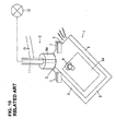
FIG. 10 , a bag 1 has a corner-cutspout attachment portion 2; andside edges 3 and 4 and abottom edge 5 are sealed, and thespout attachment portion 2 and thetop edge 6 are not sealed. As discussed in Patent Reference 1, left and right pairs ofgrippers 7 clamp or hold theside edge 3 and thetop edge 6 on both sides of thespout attachment portion 2, and the bag 1 is allowed to be hung down so that thespout attachment portion 2 is made horizontal. Thegrippers 7 are the same as the left and right pairs of grippers disclosed in Patent Reference 1 in that they are moved intermittently along a specific conveyance path and intermittently convey the clamped bag 1 along a specific conveyance path. - In
FIG. 10 , a pair of opening suction cups 8 (only one opening suction cup 8 is shown) suction-hold the films on both sides of the bag 1 at a position slightly under thespout attachment portion 2, and then they are retracted (or moved away from each other), thus opening thespout attachment portion 2. As is commonly known, when the opening suction cups 8 are retracted, thegrippers 7 are moved closer to each other so as not to hinder the opening of thespout attachment portion 2. Agas blowing member 9 disposed above the bag 1 is moved up and down; and when thespout attachment portion 2 is opened, thegas blowing member 9 is descended, the lower end of itshead 9a is brought into the opening of thespout attachment portion 2 so as to block off thespout attachment portion 2 substantially completely, and then a pressurized gas is blown into the bag 1. The reference numeral 11 is a gas channel formed in thegas blowing member 9, one end of this gas channel opens to the lower end of thehead 9a (the pressurized gas blow hole), and the other end of which is connected to a pressurizedgas supply 12. Thereference numeral 13 is an elevator member linked to thegas blowing member 9, and it is moved up and down by an elevator drive source (not shown). - Since the bag 1 is not sealed at the
top edge 6, as seen fromFIG. 10 , when pressurized gas is blown down from thegas blowing member 9, the unclosedtop edge 6 becomes an escape path for the pressurized gas, the pressurized gas freely flows out of the bag (see the white arrows inFIG. 10 ), the gas does not extend throughout the interior of the bag 1, and thecenter region 14 of the bag 1 under the spout attachment portion 2 (the region surrounded by the two-dot chain line) is particularly difficult to inflate. If thisregion 14 does not inflate completely, theregion 14, after the opening suction cups 8 are separated from the bag surface, will return to its original closed (or flat) state under the restoration force of the films of the bag 1, which results in a narrowing, deformation, etc., of the opening of thespout attachment portion 2, which means that the opening shape of thespout attachment portion 2 tends to be unstable. In particular, when the bag is clamped or held bygrippers 7 at an angle, as in this shown example, the above-described restoration force is not exerted symmetrically on both ends of thespout attachment portion 2, and the opening shape of thespout attachment portion 2 tends to be even less stable. - It is, therefore, an object of the present invention to provide a method and device for opening a spout attachment portion formed at top end of a bag that allows a stable opening shape to be obtained even for a bag whose top edge is not sealed, and this method and device is typically employed when left and right pairs of grippers clamp both sides of a spout attachment portion of a bag in which the spout attachment portion is formed by cutting off the corner of the top edge and one of the side edges of the bag, and the bag is conveyed along a specific conveyance path while being hung down, so that on this conveyance path the spout attachment portion is kept substantially horizontal and the spout attachment portion is kept opened.
- More specifically, the present invention relates to an improvement in a method for opening a spout attachment portion in which
left and right pairs of grippers clamp or hold both sides of a spout attachment portion of a bag in which this spout attachment portion is formed by cutting off the corner of the top edge and one of the side edges of the bag,
the bag is conveyed along a specific conveyance path while being hung down so that the spout attachment portion is substantially horizontal, and
in the course of this conveyance the films on both sides of the spout attachment portion are suction-held by a pair of suction cups, and then
the suction cups are moved apart to open up the spout attachment portion, after which a gas is blown into the bag by a gas blowing member to inflate the bag; and
in this method, according to the present invention,
the bag is one in which the top edge of the bag is not sealed, and
when the gas is blown into the bag by the gas blowing member, a position under the grippers on the top edge side of the bag is clamped from both sides of the bag by clamping members, thus suppressing outflow of the gas blown into the bag from the top edge. - In the present invention, it is preferable that slippage occurs between the films of the bag and the clamping faces of the clamping members when the bag is inflated.
- The device for opening a spout attachment portion of a bag according to the present invention is to carry out the above-described opening method, and it provides such a characteristic configuration as follows:
- (1) The device is comprised of:
- a pair of opening suction cups which are disposed to face both sides of the bag and are moved toward and away from each other,
- a gas blowing member which blows gas into the interior of the bag so as to inflate the bag, and
- a clamping member which open and close;
- Accordingly, it is less likely that the gas blown into the bag freely flows out from the top edge of the bag. The clamping member is provided so that when it opens it is retracted from the conveyance path of the bag.
- (2) The device can be comprised of:
- a pair of opening suction cups which are disposed to face both sides of the bag and are moved toward and away from each other,
- a gas blowing member which blows gas into the interior of the bag to inflate the bag, and
- left and right pairs of clamping members which open and close, the clamping members both having clamping faces that run along the up and down direction and
- Accordingly, it is less likely that the gas blown into the bag freely flows out from the top edge, and the gas can be blown in more efficiently to the lower region of the spout attachment portion so as to inflate this region. The left and right pairs of clamping members are provided so that when they open both are retracted from the conveyance path of the bag.
- (3) In (1) and (2) above, it is preferable that the clamping members clamp the bag with a force that is sufficient to produce slippage between the bag and the clamping faces of the clamping members when the bag is inflated.
- (4) The device is further comprised of:
- a pair of opening suction cups which are disposed to face both sides of the bag and are moved toward and away from each other,
- a gas blowing member which blows gas into the interior of the bag to inflate the bag, and
- left and right pairs of clamping members that open and close with the spacing in between can be increased or decreased,
- Accordingly, it is less likely that the gas blown into the bag freely flows out from the top edge, and the gas can be blown in more efficiently to the lower region of the spout attachment portion so as to inflate this region. The left and right pairs of clamping members are provided so that when they open both are retracted from the conveyance path of the bag.
- (5) In (1) to (4) above, the gas blowing member is moved up and down, are retracted away from the bag at the ascended position, and at the descended position the blow hole at its lower end is inserted into the bag through the spout attachment portion.
- The apparatus for manufacturing a bag equipped with a spout according to the present invention is to apply the above-described opening device to a known apparatus for manufacturing a bag that is equipped with a spout. Such a known apparatus for manufacturing a bag equipped with a spout comprises
a bag conveyance device provided with a plurality of left and right pairs of grippers that are disposed along a specific conveyance path and moved intermittently along the conveyance path, with the spacing between each other being increased or decreased along the conveyance path,
a bag supply device that is disposed near a bag supply position, which is a stop position on the conveyance path, and that supplies empty bags in a substantially vertical orientation to the grippers,
an opening device that is installed near an opening position, which is a stop position on the conveyance path, and that opens the spout attachment portion formed in the bag, a spout insertion and temporary sealing device
that is installed near a spout insertion and temporary sealing position, which is a stop position on the conveyance path,
that has a spout insertion member, which is ascended and descended substantially vertical and supports a spout, and a pair of temporary sealing members, which are disposed opposite to each other and movable toward and away from each other, and
that inserts the spout into the spout attachment portion that has been opened by the opening device and temporarily seal the spout to the spout attachment portion with the temporary sealing member; and
a final sealing device that is installed near a spout final sealing position, which is a stop position on the conveyance path, that has a pair of final sealing members disposed opposite each other and moved toward and away from each other, and that is used for the final sealing of the spout that was temporarily sealed to the spout attachment portion, to the spout attachment portion with the final sealing members. - In the apparatus for manufacturing a bag equipped with a spout according to the present invention, if needed, a corner cutting position for the bag is set, as a stop position on the conveyance path, between the bag supply position and the opening position. A corner cutting device that forms the spout attachment portion by cutting off the corner of a bag is installed near this corner cutting position.
- According to the opening method and device of the present invention, in the spout attachment portion opening step, the spout attachment portion is opened by the suction of the pair of suction cups, and pressurized gas is then blown into the bag to inflate the bag, and when the gas is thus blown into the bag, the bag is fully inflated with the pressurized gas even if the bag is of the type that the top edge is not sealed, and the bag is able to have a stable opening shape.
-
-
FIG. 1 is a top view of an apparatus for manufacturing a bag equipped with a spout according to the present invention; -
FIG. 2 ((a) through (f)) illustrates a series of steps performed by the apparatus for manufacturing a bag equipped with a spout shown inFIG. 1 ; -
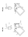
FIG. 3A and FIG. 3B illustrate in time sequence (3A and then 3B) the steps entailed by the opening procedure performed by the apparatus for manufacturing a bag equipped with a spout shown inFIG. 1 ; -
FIG. 4A and FIG. 4B illustrate in time sequence (4A and then 4B) the steps following the opening procedure ofFIG. 3B ; -
FIG. 5 illustrates another example of clamping members used in the opening procedure of the present invention; -
FIG. 6A and FIG. 6B illustrate in time sequence (6A and then 6B) the steps taken in the opening procedure in which the clamping members ofFIG. 5 are used; -
FIG. 7A and FIG. 7B illustrate in time sequence (7A and then 7B) the steps following the opening procedure ofFIG. 6B ; -
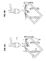
FIG. 8A and FIG. 8B illustrate in time sequence (8A and then 8B) the steps in the opening procedure in which still another type of clamping members is used; -
FIG. 9A and FIG. 9B illustrate in time sequence (9A and then 9B) the steps following the opening procedure ofFIG. 8B ; and -
FIG. 10 illustrates the problems encountered with a conventional opening device. - The method and device for supplying bags equipped with spouts according to the present invention will be described below with reference to
FIGS. 1 to 9B . InFIGS. 1 to 9B , those members and components that are substantially the same as those inFIG. 10 are numbered with the same reference numbers. - The rotary type apparatus for manufacturing bags equipped with spouts (spout attachment machine) shown in
FIG. 1 includes a bag conveyance device in which a plurality of left and right pairs ofgrippers 7 are provided around a table 10 that rotates intermittently. Thegrippers 7 are moved intermittently along a circular conveyance path; and while the grippers are thus being moved, the bags clamped or held by the grippers are intermittently conveyed along the circular conveyance path. Thegrippers 7 are moved to come closer to each other and moved away from each other at a specific timing while being moved along the conveyance path. The shown rotary apparatus for manufacturing bags each equipped with a spout is what is known as a W type (twin line) apparatus, and thus two pairs ofgrippers 7 form one set, and two sets of pairs of grippers are provided at a regular spacing along the conveyance path; and various steps for attaching spouts simultaneously to two bags clamped by two pairs ofgrippers 7 are carried out successively. - As shown in
FIG. 1 , in this apparatus for manufacturing a bag equipped with a spout, abag supply device 15 is disposed near a stop position I (bag supply step position) on the conveyance path. Thebag supply device 15 is basically the same as the bag supply device illustrated inFigure 1 of Patent Reference 1 (that comprises an empty bag storage device (12), a bag takeout device (13), a first supply device (28), and a second supply device (29)). A bag 1A (a square bag with its corner not has been cut) is positioned in a substantially horizontal orientation at the distal end of the bag storage device, and it is taken up and put in a substantially vertical orientation. The bag 1 A is then rotated by a specific angle along the bag plane (side surfaces of the bag) and is moved a specific distance along the bag plane to be supplied to thegrippers 7. The angle θ by which the bag 1A is rotated (see (a) inFIG. 2 ) is determined in advance based on the inclination angle of thespout attachment portion 2 formed in the bag. Thegrippers 7 clamp or hold, at a position that is slightly away from the corner distal end, thetop edge 6 and the side edge 3 (seeFIG. 10 ). In the above configuration, thebag supply device 15 supplies two bags 1A at a time. - A
corner cutting device 16 is disposed near a stop position II (comer cutting step position) on the conveyance path. Thecorner cutting device 16 cuts off the corner 17 of thetop edge 6 and theside edge 3 of the bag 1A (see (a) ofFIG. 2 ) within a horizontal plane to form the spout attachment portion 2 (see (b) ofFIG. 2 ). The bag with the corner thus cut is a bag 1 (which is the same as that shown inFIG. 10 ). - An
opening device 18 is disposed near a stop position III (opening step position) on the conveyance path. As shown in (c) ofFIG. 2 , theopening device 18 comprises a pair of opening suction cups 8 (only one opening suction cup 8 is depicted) that are disposed to face both sides of the bag 1 and are able to move toward and away from each other, agas blowing member 9 that is able to move up and down above the bag 1 that has stopped at the stop position III, and a clampingmember 19 that can open and close. The opening suction cups 8 and thegas blowing member 9 are the same as those shown inFIG. 10 . The clampingmember 19 has clamping faces that run in the up and down direction; and when it closes, clamp both sides of the bag at a position under the gripper 7 (the right-side gripper in (c) ofFIG. 2 ) that are positioned on thetop edge 6 side of the bag. - The steps of the opening procedure of the bag will now be described below in more detail and in time sequence with reference to
FIGS. 3A through FIG. 4B . - (1) As shown in
FIG. 3A , when the bag 1 clamped by thegrippers 7 is stopped at the stop position III, the opening suction cups 8 are moved closer together and suction-hold the films on both sides of the bag 1 near thespout attachment portion 2. At this point thegas blowing member 9 is in its ascended position, and the clampingmember 19 opens and is retracted from the conveyance path of the bag 1. - (2) The opening suction cups 8 are moved apart or away from each other, and at the same time the
grippers 7 are moved closer together (seeFIG. 3B ). As a result, thespout attachment portion 2 is opened. - (3) Then, as shown in
FIG. 4A , thegas blowing member 9 is descended, the lower end of thehead 9a of thegas blowing member 9 goes into the bag through the opening of thespout attachment portion 2, substantially blocking off the opening of thespout attachment portion 2. Either simultaneously with the descending of thegas blowing member 9, or before or after it, the clampingmember 19 closes and lightly clamp the bag 1 from both sides in the up and down direction at a position under thegripper 7 that is on thetop edge 6 side of the bag. Then, pressurized gas is blown into the bag from thegas blowing member 9. The clampingmember 19 clamps at a position under the gripper that is on thetop edge 6 side and all the way to a position that reaches the side edge 4 substantially in the vertical direction of the bag; accordingly, the clamping member makes a situation that the escape path of the pressurized gas (the unsealed top edge 6) is to a large extent blocked off, and the pressurized gas is less likely to flow out of the bag from thetop edge 6, and as a result, the pressurized gas proceeds farther into the interior of the bag 1 (see theregion 14 inFIG. 10 ) and inflates substantially the entire bag 1. - The force exerted by the clamping
member 19 to clamp the bag 1 is set to be enough to produce slippage between the films on both sides of the bag 1 and the clamping faces of the clampingmember 19 when the bag lis inflated. Therefore, as the bag 1 is inflated, the films of the bag 1 can shift toward the center of the bag through the clamped portion, and this allows the entire bag 1 to be uniformly and completely inflated, without any distortion. - (4) When the bag 1 has been inflated, the blowing of the pressurized gas from the
gas blowing member 9 is stopped, and then thegas blowing member 9 is ascended. The suction of the suction cups 8 is stopped, and then the suction cups 8 are retracted to their original positions, and the clampingmember 19 is opened (seeFIG. 4B ) and are retracted from the conveyance path of the bag 1. At this point, the bag 1 is sufficiently inflated; accordingly, the opening shape of thespout attachment portion 2 is stable and kept maintained "as is". Thegrippers 7 are then moved and convey the bag 1 toward the next stop position IV (spout insertion and temporary sealing step position). - Near the stop position IV on the conveyance path (spout insertion and temporary sealing step position), as seen from
FIG.1 , aspout supply conveyor 21, a parts feeder 22, and a spout insertion andtemporary sealing device 23 are disposed. The spout insertion andtemporary sealing device 23, as shown in (d) ofFIG. 2 , inserts aspout 25 that is held by aspout insertion member 24 into the center of the opening of the openedspout attachment portion 2, then thespout 25 is squeezed from the outside of the bag 1 by a pair of spout temporary sealing members 26 (hot plates) so that thespout 25 is sealed temporarily to the films on both sides of the bag 1. After the insertion of thespout 25, thegrippers 7 are moved away from each other so as to close the opening of thespout attachment portion 2. - As seen from
FIG. 1 , afirst sealing device 27 is disposed near the stop position V (first sealing step position) on the conveyance path, asecond sealing device 28 is disposed near the stop position VI (second sealing step position), and athird sealing device 29 is disposed near the stop position VII (third sealing step position). Thefirst sealing device 27 squeezes the bag 1 and thespout 25 with a pair ofhot plates 31 thereof as shown in (e) ofFIG. 2 and executes final sealing to the bag 1 and the spout 25 (in which thespout 25 is sealed to the films on both sides of thespout attachment portion 2 of the bag 1, and at the same time the films on both sides of thespout attachment portion 2 of the bag 1 are sealed together). This final sealing is performed in the same way by thesecond sealing device 28 and by thethird sealing device 29. Performing the final sealing step just once or many times repeatedly can be selected optionally. - A cooling device 32 is disposed near the stop position VIII (cooling step position, see
FIG. 1 ) on the conveyance path. The cooling device 32 squeezes the bag 1 and thespout 25 with a pair of coolingplates 33 to cool the heated sealed portions of the bag 1 and thespout 25. - A
bag discharge device 34 and aconveyor 35 are disposed near the stop position IX (discharge step position) on the conveyance path. Thegrippers 7 are opened (see (f)FIG. 2 ), thebag discharge device 34 receive two finished bags 1B (bags equipped with spouts) together, and then thebag discharge device 34 arranges the bags 1B on theconveyor 35. On theconveyor 35, the following bags come in under the preceding bags (seeFigure 7 in Japanese Patent Application Laid-Open (Kokai) No.H8-337217 conveyor 35 is a conveyor magazine type conveyor that supplies the bags 1B equipped with spouts to a filling device (not shown), and the numerous stacked bags 1B are supplied "as is" to the filling device. - In
FIG. 1 , thereference numeral 36 is a control device. Thecontrol device 36 controls all of the devices that make up the apparatus for manufacturing bags having spouts shown inFIG. 1 . In other words, thecontrol device 36 controls the above-described bag conveyance device (the table 10, thegrippers 7, etc.), thebag supply device 15, thecorner cutting device 16, theopening device 18, the spout insertion andtemporary sealing device 23, etc. -
FIG. 5 shows an example of another type of clamping member of the present invention. - The clamping
member 37 shown inFIG. 5 is the same as the clampingmember 19 in that it clamps or holds both sides of the bag 1 at a position under thegripper 7 which is on thetop edge 6 side all the way to the side edge 4 of a bag; however, it differs from the clampingmember 19 described above in that it is provided at an angle to the horizontal plane so as to be substantially parallel to thetop edge 6 of the bag. - When the clamping
member 37 is used, just as in the case of the clampingmember 19, the escape path of the pressurized gas (the unsealed top edge 6) is blocked off, and it is less likely that the pressurized gas will flow out of the bag from thetop edge 6; and as a result, the pressurized gas proceeds well into the interior of the bag 1 and inflates substantially the entire bag 1. In any case, the clamping members of the present invention clamp the bag 1 in any form, so as long as the pressurized gas is prevented to a certain extent from freely flowing out of the bag from thetop edge 6 of the bag, and the clamping members help to inflate the bag 1 completely. -
FIGS. 6A through 7B illustrate in time sequence the opening procedure when still another type of clamping members are used. In the opening procedure shown inFIGS. 6A through 7B , left and right pairs of clampingmembers gas blowing member 9 are the same as those shown inFIGS. 3A through 4B . The clampingmembers side clamping member 38 clamps from both sides of the bag 1 at a position under thegripper 7 which is on thetop edge 6 side, and the left-side clamping member 39 clamps at a position under thegripper 7 which is on theside edge 3 side. - The steps of bag opening procedure of the clamping
members FIGS. 6A through 7B . - (1) As shown in
FIG. 6A , when the bag 1 clamped by thegrippers 7 stops at the stop position III (seeFIG. 1 ), the opening suction cups 8 are moved closer to each other and suction-hold both side planes (both side surfaces) of the bag 1 near thespout attachment portion 2. At this point, thegas blowing member 9 is in its ascended position, and the clampingmembers - (2) The opening suction cups 8 are moved apart or away from each other, and at the same time the
grippers 7 are moved closer to each other (seeFIG. 6B ) as indicated by arrows. As a result, thespout attachment portion 2 of the bag 1 is opened. - (3) As shown in
FIG. 7A , thegas blowing member 9 is then descended, and the lower end of thehead 9a is inserted into the bag 1 from the opening of the openedspout attachment portion 2, substantially blocking off the opening of thespout attachment portion 2. Either simultaneously with the descending of thegas blowing member 9, or before or after it, the clampingmember 38 closes and the clampingmember 39 also closes, thus lightly clamping the bag 1 from both sides of the bag substantially in the vertical direction, with the clampingmember 38 at a position under the gripper 7 (right side gripper 7) that is on thetop edge 6 side, and the clampingmember 39 at a position under the gripper 7 (left side gripper 7) on theside edge 3 side. The lower end of the clampingmember 38 clamping the bag 1 reaches all the way to the side edge 4 of the bag 1. As to the manner the clampingmembers members spout attachment portion 2. Pressurized gas is then blown into the bag from thegas blowing member 9. The pressurized gas goes into a region 41 (the region directly under the opened spout attachment portion 2) squeezed by the clampingmembers member 38 clamps the position under the gripper on thetop edge 6 side and thereby blocks off to a considerable extent the escape path of the pressurized gas (the unsealed top edge 6), so that the pressurized gas is less likely to flow out of the bag from thetop edge 6, and as a result mainly theregion 41 of the bag is inflated. - The force exerted by the clamping
members member 19, so that that force is enough to produce slippage between the films on both sides of the bag 1 and the clamping faces of the clampingmembers region 41 of the bag 1 is inflated, the films of the bag 1 move toward the center through the clamped positions, and this allows the bag 1 to be completely inflated in theregion 41 clamped by the clampingmembers - (4) The blowing of the pressurized gas from the
gas blowing member 9 is, next, stopped, and then thegas blowing member 9 is ascended, the suction of the suction cups 8 is stopped, the suction cups 8 are retracted to their original positions, and the clampingmembers spout attachment portion 2 is stable and kept maintained. Thegrippers 7 are then moved and convey the bag 1 toward the next stop position IV (spout insertion and temporary sealing step position). -
FIGS. 8A through 9B illustrate in time sequence an opening procedure in which a still another type of clamping members are used; and in the opening procedure shown inFIGS. 8A through 9B , left and right pairs of clampingmembers gas blowing member 9 are the same as those shown inFIGS. 6A through 7B . The shape and layout of the clampingmembers members members members - The steps involved in the opening procedure of the bag 1 will be described below in detail and in time sequence with reference to
FIGS. 8A through 9B . - (1) As shown in
FIG. 8A , when the bag 1 clamped by thegrippers 7 is stopped at the stop position III (seeFIG. 1 ), the opening suction cups 8 are moved closer to each other and suction-hold both sides of the bag 1 near thespout attachment portion 2 of the bag. At this point, thegas blowing member 9 is at its ascended position, and the clampingmembers - (2) The opening suction cups 8 are next moved away from each other, and at the same time the
grippers 7 are moved so that the spacing of thegrippers 7 is narrowed from D0 to D1 (seeFIGS. 8A and 8B ). This opens up thespout attachment portion 2 of the bag 1. - (3) As shown in
FIG. 9A , thegas blowing member 9 is then descended, and the lower end of thehead 9a is inserted into the bag from the opening of thespout attachment portion 2, thus substantially blocking off the opening of thespout attachment portion 2. Either simultaneously with the descending of thegas blowing member 9, or before or after it, the clampingmembers member 42 holds the bag at a position under thegrippers 7 on thetop edge 6 side and the clampingmember 43 holds the bag at a position under thegripper 7 on theside edge 3 side. It can thus be said that the clampingmembers spout attachment portion 2. In the above respects these are the same as the previously described clampingmembers members members members members members members - (4) As shown in
FIG. 9B , pressurized gas is then blown into the bag from thegas blowing member 9. The pressurized gas goes into aregion 44 of the bag (the region directly under the opened spout attachment portion 2) which is squeezed by the clampingmembers member 42 clamps the position under the gripper on thetop edge 6 side (the unsealed top edge 6) and thereby blocks off to a considerable extent the escape path of the pressurized gas, so that the pressurized gas is less likely to flow out of the bag from thetop edge 6, and as a result mainly theregion 44 is inflated. Also, the spacing d1 between the clampingmembers members - If the force exerted when the clamping
members members members region 44 squeezed by the clampingmembers members members members - (5) The blowing of the pressurized gas from the
gas blowing member 9 is next stopped, and then thegas blowing member 9 is ascended, the suction cups 8 are retracted to their original positions, and then the clampingmembers spout attachment portion 2 is stable and kept "as is". Thegrippers 7 are then moved and convey the bag 1 toward the next stop position IV (spout insertion and temporary sealing step position). - The embodiments of the method and device for opening a spout attachment portion of a bag and of the apparatus for manufacturing a bag equipped with a spout according to the present invention are as described above, and the present invention further provides such embodiments as those described below:
- (1) In the above examples, the bag 1 supplied from the
bag supply device 15 to thegrippers 7 is the square bag 1A that has no corner-cut, so that the apparatus for manufacturing a bag equipped with a spout performs corner cutting and forms thespout attachment portion 2 at this corner. However, as disclosed in Patent Reference 1, a bag (the bag 1) that has a corner-cut made in advance can be supplied to thegrippers 7. In this case, the corner cutting step on the conveyance path of the bag 1 is not necessary. - (2) In the above examples, the
bag supply device 15 is basically the same as the bag supply device shown inFigure 1 of Patent Reference 1; however, the bag supply device disclosed in, for instance, Japanese Patent Application No.2014-043864 2014-043864 - (3) The apparatus for manufacturing a bag equipped with a spout described for the above examples is a spout attachment machine that merely attaches the
spout 25 to the bag 1; however, the device can be designed so that bag 1 is filled with a liquid. In this case, after the spout attachment step is done, the spout attachment machine opens thetop edge 6 of the bag (while still being clamped by the same grippers 7) on the same conveyance path, then it fills the bag 1 with the liquid through thetop edge 6 and seals thetop edge 6 after filling. In this case, the bag equipped with a spout that is manufactured is an already-filled bag. - (4) In the above examples, the
spout attachment portion 2 is opened by the opening suction cups 8, and the clampingmembers gas blowing member 9 into the bag. However, the blowing in of the pressurized gas can be started before the opening of thespout attachment portion 2 or before the closing of the clamping members. In any case, the timing of the opening of thespout attachment portion 2, the clamping by the clamping members, and the start of the blowing of the pressurized gas can be selected as desired. - (5) In the above examples, the clamping
members members 38 and the clampingmembers 39. The same applies to the clampingmembers - (6) In the above examples, when the
gas blowing member 9 is descended, the lower end of thehead 9a is inserted into the opening of thespout attachment portion 2, thus substantially blocking off the opening of thespout attachment portion 2, which prevents the opening of thespout attachment portion 2 from becoming an escape path for the pressurized gas, so that the bag 1 is reliably inflated with the pressurized gas; however, this is not essential. The present invention can be carried out even if the blow hole at the lower end of thegas blowing member 9 is not inserted into the opening of thespout attachment portion 2. -
- 1
- Bag
- 2
- Spout attachment portion
- 3,4
- Side edge of bag
- 6
- Top edge of bag
- 7
- Grippers
- 8
- Opening suction cup
- 9
- Gas blowing member
- 18
- Opening device
- 19, 37, 38, 39, 42, 43
- Clamping members
- 25
- Spout
Claims (13)
- A method for opening a spout attachment portion, in which
a pair of grippers
clamp both sides of a spout attachment portion of a bag in which a corner at a top edge and one of side edges of the bag has been cut to form the spout attachment portion; and
convey the bag along a specific conveyance path while having the bag hung down so that the spout attachment portion is substantially horizontal,
a pair of suction cups suction-hold films on both sides of the spout attachment portion of the bag during the conveyance, and then a spacing between the pair of suction cups is widened to open the spout attachment portion, and thereafter
a gas blowing member blows a gas into the bag to inflate the bag,
wherein
the bag is unsealed at the top edge, and
when the gas is blown into the bag by the gas blowing member, a clamping member clamps a position under the gripper on the top edge side of the bag from both sides of the bag, thus suppressing outflow of the gas blown into the bag from the top edge. - The method for opening a spout attachment portion according to Claim 1, wherein when the bag is inflated, slippage is allowed to occur between the films and a clamping face of the clamping member.
- A device for opening a spout attachment portion, in which
a spout attachment portion is formed in a bag by cutting a corner at a top edge and one of side edges of the bag, a pair of grippers that are movable closer to each other or away from each other clamp both sides of the spout attachment portion, and the bag is conveyed along a specific conveyance path while being hung down so that the spout attachment portion is substantially horizontal,
wherein
the bag is unsealed at the top edge; and
the device comprises
a pair of opening suction cups that are disposed to face both sides of the bag and are movable toward and away from each other,
a gas blowing member that blows gas into an interior of the bag to inflate the bag,
and
a clamping member that opens and closes; and
the clamping member when closes clamps both sides of the bag at a position under the gripper on the top edge-side and when opens is retracted from the conveyance path of the bag. - A device for opening a spout attachment portion, in which
a spout attachment portion is formed in a bag by cutting a corner at a top edge and one of side edges of the bag, a pair of grippers that are movable closer to each other or away from each other clamp both sides of the spout attachment portion, and the bag is conveyed along a specific conveyance path while being hung down so that the spout attachment portion is substantially horizontal,
wherein
the bag is unsealed at the top edge, and
the device comprises
a pair of opening suction cups that are disposed to face both sides of the bag and are movable toward and away from each other,
a gas blowing member that blows gas into an interior of the bag to inflate the bag; and
a pair of clamping members that open and close; and
each of the clamping members has clamping faces that run along an up and down direction,
when one of the pair of the clamping members closes, a position under the gripper on the top edge side of the bag is clamped thereby from both sides of the bag, and when another one of the pair of the clamping members closes, a position under the gripper on one of the side edges side of the bag is clamped thereby from both sides of the bag, and
when open, the pair of the clamping members are retracted from the conveyance path of the bag. - The device for opening a spout attachment portion according to Claim 3 or 4, wherein when the bag is inflated, the clamping members clamp the bag with a force sufficient to produce slippage between films on both sides of the bag and clamping faces of the clamping members.
- A device for opening a spout attachment portion, in which
a spout attachment portion is formed in a bag by cutting a corner at a top edge and one of side edges of the bag, a pair of grippers that are movable closer to each other or away from each other clamp both sides of the spout attachment portion, and the bag is conveyed along a specific conveyance path while being hung down so that the spout attachment portion is substantially horizontal,
wherein
the bag is unsealed at the top edge, and
the device comprises
a pair of opening suction cups that are provided to face both sides of the bag and are movable toward and away from each other,
a gas blowing member that blows gas into an interior of the bag to inflate the bag,
and
a pair of clamping members that open and close and whose spacing is increased or decreased, the clamping members both having clamping faces that run along up and down direction,
when one of the pair of the clamping members closes, a position under the gripper on the top edge side of the bag is clamped thereby from both sides of the bag, and when another one of the pair of the clamping members closes, a position under the gripper on one of the side edges side of the bag is clamped thereby from both sides of the bag, and
when open, the pair of the clamping members are retracted from the specific conveyance path of the bag. - The device for opening a spout attachment portion according to any one of Claims 3 to 6, wherein the gas blowing member is movable up and down, is retracted away from the bag at an ascended position thereof, and at a descended position thereof a blow hole at a lower end thereof is inserted into the bag through the spout attachment portion.
- An apparatus for manufacturing a bag equipped with a spout, comprising
a bag conveyance device provided with a plurality of pairs of grippers that are disposed along a specific conveyance path and moved intermittently along the conveyance path, a spacing between a pair of grippers is increased or decreased on the conveyance path;
a bag supply device that is disposed near a bag supply position, which is a stop position on the conveyance path, and that supplies empty bags in a substantially vertical orientation to the grippers;
an opening device that is installed near an opening position, which is a stop position on the conveyance path, and that opens a spout attachment portion formed in the bag;
a spout insertion and temporary sealing device
that is installed near a spout insertion and temporary sealing position, which is a stop position on the conveyance path,
that has a spout insertion member, which is ascended and descended substantially vertical and supports a spout, and a pair of temporary sealing members, which are disposed opposite to each other and movable toward and away from each other, and
that inserts the spout into the spout attachment portion that has been opened by the opening device and temporarily seal the spout to the spout attachment portion with the temporary sealing member; and
a final sealing device
that is installed near a spout final sealing position, which is a stop position on the conveyance path,
that has a pair of final sealing members which are disposed opposite to each other and movable toward and away from each other, and
that is used for final sealing of the spout, which is temporarily sealed to the spout attachment portion, to the spout attachment portion with the final sealing members;
in which
the bag is unsealed at the top edge, and
the spout attachment portion is a portion formed by cutting off a corner at the top edge and one of side edge, a pair of grippers clamp both sides of the spout attachment portion so that the bag is hung down with the spout attachment portion substantially horizontal, and
wherein the opening device comprises
a pair of opening suction cups that are disposed to face both sides of the bag and are movable toward and away from each other;
a gas blowing member that inflates the bag by blowing gas into an interior of the bag; and
a clamping member that opens and closes, and
when closes, the clamping member clamps both sides of the bag at a position under the grippers on the top edge side, and
when opens the clamping member is retracted from the conveyance path of the bag. - An apparatus for manufacturing a bag equipped with a spout, comprising
a bag conveyance device provided with a plurality of pairs of grippers that are disposed along a specific conveyance path and moved intermittently along the conveyance path, a spacing between a pair of grippers is increased or decreased on the conveyance path;
a bag supply device that is disposed near a bag supply position, which is a stop position on the conveyance path, and that supplies empty bags in a substantially vertical orientation to the grippers;
an opening device that is installed near an opening position, which is a stop position on the conveyance path, and that opens a spout attachment portion formed in the bag;
a spout insertion and temporary sealing device
that is installed near a spout insertion and temporary sealing position, which is a stop position on the conveyance path,
that has a spout insertion member, which is ascended and descended substantially vertical and supports a spout, and a pair of temporary sealing members, which are disposed opposite to each other and movable toward and away from each other, and
that inserts the spout into the spout attachment portion that has been opened by the opening device and temporarily seal the spout to the spout attachment portion with the temporary sealing member; and
a final sealing device
that is installed near a spout final sealing position, which is a stop position on the conveyance path,
that has a pair of final sealing members which are disposed opposite to each other and movable toward and away from each other, and
that is used for final sealing of the spout, which is temporarily sealed to the spout attachment portion, to the spout attachment portion with the final sealing members;
in which
the bag is unsealed at the top edge, and
the spout attachment portion is a portion formed by cutting off a corner at the top edge and one of side edge, a pair of grippers clamp both sides of the spout attachment portion so that the bag is hung down with the spout attachment portion substantially horizontal, and
wherein the opening device comprises
a pair of opening suction cups that are disposed to face both sides of the bag and are movable toward and away from each other;
a gas blowing member that inflates the bag by blowing gas into an interior of the bag; and
a pair of clamping members that open and close, and
each one of the clamping members has a clamping face that runs in up and down direction,
when one of the pair of clamping members closes, a position under the gripper on the top edge side is clamped thereby from both sides of the bag, and when another one of the pair of clamping members closes, a position under the gripper on one of side edges side of the bag is clamped thereby from both sides of the bag, and
when open, the pair of clamping members are retracted from the conveyance path of the bag. - The apparatus for manufacturing a bag equipped with a spout according to Claim 8 or 9, wherein the clamping members clamp the bag with a force sufficient to produce slippage between films on both sides of the bag and the clamping faces of the clamping members when the bag is inflated.
- An apparatus for manufacturing a bag equipped with a spout, comprising
a bag conveyance device provided with a plurality of pairs of grippers that are disposed along a specific conveyance path and moved intermittently along the conveyance path, a spacing between a pair of grippers is increased or decreased on the conveyance path;
a bag supply device that is disposed near a bag supply position, which is a stop position on the conveyance path, and that supplies empty bags in a substantially vertical orientation to the grippers;
an opening device that is installed near an opening position, which is a stop position on the conveyance path, and that opens a spout attachment portion formed in the bag;
a spout insertion and temporary sealing device
that is installed near a spout insertion and temporary sealing position, which is a stop position on the conveyance path,
that has a spout insertion member, which is ascended and descended substantially vertical and supports a spout, and a pair of temporary sealing members, which are disposed opposite to each other and movable toward and away from each other, and
that inserts the spout into the spout attachment portion that has been opened by the opening device and temporarily seal the spout to the spout attachment portion with the temporary sealing member; and
a final sealing device
that is installed near a spout final sealing position, which is a stop position on the conveyance path,
that has a pair of final sealing members which are disposed opposite to each other and movable toward and away from each other, and
that is used for final sealing of the spout, which is temporarily sealed to the spout attachment portion, to the spout attachment portion with the final sealing members;
in which
the bag is unsealed at the top edge, and
the spout attachment portion is a portion formed by cutting off a corner at the top edge and one of side edge, a pair of grippers clamp both sides of the spout attachment portion so that the bag is hung down with the spout attachment portion substantially horizontal, and
wherein the opening device comprises
a pair of opening suction cups that are disposed to face both sides of the bag and are movable toward and away from each other;
a gas blowing member that inflates the bag by blowing gas into an interior of the bag; and
a pair of clamping members that open and close and whose spacing is increased or decreased, the clamping members both having clamping faces that run along up and down direction, and
when one of the pair of clamping members closes, a position under the gripper on the top edge side is clamped thereby from both sides of the bag, and when another one of the pair of clamping member closes, a position under the gripper on one of side edges side of the bag is clamped thereby from both sides of the bag, and
when open, the pair of clamping members are retracted from the conveyance path of the bag. - The apparatus for manufacturing a bag equipped with a spout according to any one of Claims 8 to 11, wherein
the gas blowing member is moveable up and down and are retracted away from the bag at an ascended position thereof, and
at a descended position a blow hole at the lower end of the gas blowing member is inserted into the bag through the spout attachment portion. - The apparatus for manufacturing a bag equipped with a spout according to any one of Claims 8 to 12, wherein
a corner cutting position of the bag is set, as a stop position on the conveyance path, between the bag supply position and the opening position; and
a corner cutting device that is installed near the corner cutting position and forms the spout attachment portion by cutting off the corner is provided.
Applications Claiming Priority (1)
| Application Number | Priority Date | Filing Date | Title |
|---|---|---|---|
| JP2014146882A JP6315462B2 (en) | 2014-07-17 | 2014-07-17 | Method and apparatus for opening spout attachment portion of bag |
Publications (2)
| Publication Number | Publication Date |
|---|---|
| EP2974856A1 true EP2974856A1 (en) | 2016-01-20 |
| EP2974856B1 EP2974856B1 (en) | 2018-10-10 |
Family
ID=53783551
Family Applications (1)
| Application Number | Title | Priority Date | Filing Date |
|---|---|---|---|
| EP15002112.9A Not-in-force EP2974856B1 (en) | 2014-07-17 | 2015-07-16 | Method and device for opening spout attachment portion of a bag |
Country Status (6)
| Country | Link |
|---|---|
| US (1) | US10124919B2 (en) |
| EP (1) | EP2974856B1 (en) |
| JP (1) | JP6315462B2 (en) |
| KR (1) | KR102121378B1 (en) |
| CN (1) | CN105270682B (en) |
| ES (1) | ES2702224T3 (en) |
Families Citing this family (16)
| Publication number | Priority date | Publication date | Assignee | Title |
|---|---|---|---|---|
| ES2678995T3 (en) * | 2015-03-13 | 2018-08-21 | Ecolean Ab | Equipment and method for filling a bag type container |
| US10840121B2 (en) * | 2016-10-31 | 2020-11-17 | Taiwan Semiconductor Manufacturing Co., Ltd. | Method and apparatus for unpacking semiconductor wafer container |
| KR101854537B1 (en) * | 2016-11-10 | 2018-06-08 | 김상근 | Cap automatic install system of vinyl bag inlet |
| EP3914518A1 (en) * | 2019-04-02 | 2021-12-01 | Automated Packaging Systems, LLC. | Packaging machine for opening bags on a web of bags and methods of using the same |
| JP7297094B2 (en) * | 2019-04-23 | 2023-06-23 | スマート ボトル,インコーポレーテッド | Flexible container and process for placing accessories therein |
| BR112021023458A2 (en) * | 2019-05-22 | 2022-02-01 | Flexible Packaging Company S L | Machine for packaging products in preformed flexible packaging with closing element |
| CN111002636B (en) * | 2020-01-09 | 2024-12-03 | 佛山市天正机械有限公司 | Packaging bag nozzle rotary welding machine |
| CN112110086B (en) * | 2020-09-20 | 2022-04-22 | 海宁金都新能源有限公司 | A bag opening mechanism in a garbage recycling device |
| CN112265326B (en) * | 2020-09-25 | 2022-04-15 | 南京沪江复合材料股份有限公司 | Online ton sack cornering machine |
| JP7766396B2 (en) * | 2020-10-27 | 2025-11-10 | Pacraft株式会社 | Bag processing method and bag processing device |
| NL2028767B1 (en) * | 2021-07-16 | 2023-01-23 | Dd Innovations B V | Device for packaging of medicine-units |
| CN116062268B (en) * | 2023-03-06 | 2023-07-11 | 成都圣恩生物科技股份有限公司 | Packaging bag unsealing device, unsealing method and stir-frying device |
| CN116811352B (en) * | 2023-07-06 | 2025-09-12 | 四川维克多工业有限公司 | Valve bag edge sealing mechanism and production device |
| CN117141054B (en) * | 2023-10-30 | 2024-07-12 | 泉州市野途运动用品有限公司 | Automatic assembly equipment for water absorption bags |
| CN117533561B (en) * | 2024-01-10 | 2024-03-26 | 河北云山化工集团有限公司 | Reduce remaining emulsion explosive equipment for packing |
| CN119058167B (en) * | 2024-11-06 | 2024-12-27 | 江苏爱舍伦医疗科技集团股份有限公司 | Automatic production equipment and production process for medical liquid collecting bag |
Citations (5)
| Publication number | Priority date | Publication date | Assignee | Title |
|---|---|---|---|---|
| JP2002128025A (en) | 2000-10-26 | 2002-05-09 | Toyo Jidoki Co Ltd | Bag opening apparatus and bag opening method in bag packing machine using flat bags |
| JP2014043864A (en) | 2012-08-24 | 2014-03-13 | Yamato Scient Co Ltd | Support device for seismic isolator, and seismic isolator with support device for seismic isolator |
| EP2712727A2 (en) * | 2012-09-26 | 2014-04-02 | Toyo Jidoki Co., Ltd. | Method and apparatus for manufacturing spout-equipped bags |
| JP5459114B2 (en) | 2010-07-07 | 2014-04-02 | 大日本印刷株式会社 | Packaging bag manufacturing method |
| US20140102045A1 (en) * | 2012-10-12 | 2014-04-17 | Toyo Jidoki Co., Ltd. | Bag Mouth Opening Method And Apparatus For Use In Bag Filling And Packaging |
Family Cites Families (25)
| Publication number | Priority date | Publication date | Assignee | Title |
|---|---|---|---|---|
| US3592004A (en) * | 1969-08-22 | 1971-07-13 | Riegel Paper Corp | Bag-pressing members for packaging machine |
| GB1455348A (en) * | 1974-07-18 | 1976-11-10 | Smidth & Co As F L | Rotary packer for filling sacks |
| DE3441947A1 (en) | 1984-11-16 | 1986-05-28 | Robert Bosch Gmbh, 7000 Stuttgart | Method and apparatus for opening a flat bag |
| JP3261543B2 (en) * | 1992-07-23 | 2002-03-04 | 東洋自動機株式会社 | Automatic filling and packaging method for bags with spouts with caps |
| US5606844A (en) * | 1993-12-27 | 1997-03-04 | Sumitomo Bakelite Company, Limited | Process for producing a self-supporting package having an outlet stopper and an apparatus for producing said package |
| JPH08337217A (en) | 1995-06-09 | 1996-12-24 | Toyo Jidoki Co Ltd | Packaging material supply device |
| JP2001315718A (en) * | 2000-02-23 | 2001-11-13 | Toyo Jidoki Co Ltd | Sealing method for sealing portion of packaging container, heat treatment plate used for the sealing method, and inspection method for sealing portion |
| JP2001260255A (en) * | 2000-03-16 | 2001-09-25 | Fine Device:Kk | Opening method of cutting edge of polymer sheet |
| JP4721024B2 (en) * | 2001-01-26 | 2011-07-13 | 不双産業株式会社 | Package manufacturing equipment |
| JP3902056B2 (en) * | 2002-04-22 | 2007-04-04 | 株式会社フジシールインターナショナル | Manufacturing method and manufacturing apparatus for bag-like container with mouth member |
| CA2504710A1 (en) * | 2002-10-30 | 2004-05-21 | Ppi Technologies, Inc. | Flexible pouch and method of forming a flexible pouch |
| ITPR20020078A1 (en) * | 2002-12-20 | 2004-06-21 | Procomac Spa | PROCEDURE AND OPENING DEVICE OF A FLEXIBLE BAG. |
| EP1739025B1 (en) * | 2004-04-19 | 2011-06-22 | Fuji Seal International, Inc. | Pouch and method of producing pouch container with spout |
| US20080247682A1 (en) * | 2007-04-03 | 2008-10-09 | Pouch Pac Innovations, Llc | Stand-up flexible pouch and method of forming |
| JP4530882B2 (en) * | 2005-03-04 | 2010-08-25 | 東洋自動機株式会社 | Method for manufacturing spouted bag |
| TW200914328A (en) * | 2007-09-26 | 2009-04-01 | Chieh-Hua Liao | Inflation apparatus for continuously inflating type airtight body and inflating method thereof |
| SE0702170L (en) * | 2007-09-28 | 2009-03-10 | Ecolean Res & Dev As | Method of gas filling a handle portion of a package and method of producing a package |
| CN201128496Y (en) * | 2007-12-27 | 2008-10-08 | 贾艳 | Bag opening machine for self-supporting bag |
| JP5197093B2 (en) * | 2008-03-28 | 2013-05-15 | 東洋自動機株式会社 | Empty bag supply method and empty bag supply device |
| DE102011078975A1 (en) * | 2011-07-11 | 2013-01-17 | Böwe Systec Gmbh | Apparatus and method for opening a shell |
| JP5913992B2 (en) * | 2012-01-12 | 2016-05-11 | 東洋自動機株式会社 | Bag mouth opening method and opening device |
| KR101594212B1 (en) | 2012-12-20 | 2016-02-15 | 코오롱인더스트리 주식회사 | Protective Net and Method for Manufacturing The Same |
| JP6010487B2 (en) * | 2013-03-05 | 2016-10-19 | 東洋自動機株式会社 | Gas sealing method and gas sealing device for bag with airbag |
| JP6140086B2 (en) * | 2014-02-06 | 2017-05-31 | 東洋自動機株式会社 | Bag transfer device |
| JP6243756B2 (en) | 2014-03-06 | 2017-12-06 | 東洋自動機株式会社 | Spout mounting bag supply method and apparatus |
-
2014
- 2014-07-17 JP JP2014146882A patent/JP6315462B2/en active Active
-
2015
- 2015-06-02 KR KR1020150077693A patent/KR102121378B1/en not_active Expired - Fee Related
- 2015-07-16 US US14/801,690 patent/US10124919B2/en active Active
- 2015-07-16 EP EP15002112.9A patent/EP2974856B1/en not_active Not-in-force
- 2015-07-16 ES ES15002112T patent/ES2702224T3/en active Active
- 2015-07-17 CN CN201510421114.8A patent/CN105270682B/en not_active Expired - Fee Related
Patent Citations (6)
| Publication number | Priority date | Publication date | Assignee | Title |
|---|---|---|---|---|
| JP2002128025A (en) | 2000-10-26 | 2002-05-09 | Toyo Jidoki Co Ltd | Bag opening apparatus and bag opening method in bag packing machine using flat bags |
| JP5459114B2 (en) | 2010-07-07 | 2014-04-02 | 大日本印刷株式会社 | Packaging bag manufacturing method |
| JP2014043864A (en) | 2012-08-24 | 2014-03-13 | Yamato Scient Co Ltd | Support device for seismic isolator, and seismic isolator with support device for seismic isolator |
| EP2712727A2 (en) * | 2012-09-26 | 2014-04-02 | Toyo Jidoki Co., Ltd. | Method and apparatus for manufacturing spout-equipped bags |
| JP2014080013A (en) | 2012-09-26 | 2014-05-08 | Toyo Jidoki Co Ltd | Method and apparatus for producing spout-provided bag |
| US20140102045A1 (en) * | 2012-10-12 | 2014-04-17 | Toyo Jidoki Co., Ltd. | Bag Mouth Opening Method And Apparatus For Use In Bag Filling And Packaging |
Also Published As
| Publication number | Publication date |
|---|---|
| JP6315462B2 (en) | 2018-04-25 |
| KR102121378B1 (en) | 2020-06-10 |
| CN105270682A (en) | 2016-01-27 |
| US20160016693A1 (en) | 2016-01-21 |
| US10124919B2 (en) | 2018-11-13 |
| JP2016022961A (en) | 2016-02-08 |
| EP2974856B1 (en) | 2018-10-10 |
| KR20160011568A (en) | 2016-02-01 |
| CN105270682B (en) | 2019-04-12 |
| ES2702224T3 (en) | 2019-02-28 |
Similar Documents
| Publication | Publication Date | Title |
|---|---|---|
| EP2974856B1 (en) | Method and device for opening spout attachment portion of a bag | |
| EP2746169B1 (en) | Gas charging method and gas charging apparatus for a bag equipped with gas compartment | |
| JP6010487B2 (en) | Gas sealing method and gas sealing device for bag with airbag | |
| AU2008305801B2 (en) | Method for gas filling of a handle portion of a container | |
| EP1780129A1 (en) | Gas seal-in method for a bag with a gas filling compartment and packaging method for such a bag | |
| ES2597833T3 (en) | Method and device for sealing gas in a bag equipped with a gas compartment | |
| EP2933198A1 (en) | Bag filling and packaging method and bag filling and packaging apparatus | |
| EP2712727A2 (en) | Method and apparatus for manufacturing spout-equipped bags | |
| EP1787912A1 (en) | Bag with a gas filling compartment, method for manufacturing the same, method for sealing gas in the same and method for packaging the same | |
| WO2008015773A1 (en) | Spout mounting method and spout | |
| CN104058138B (en) | Gas Charging Method And Gas Charging Apparatus For A Bag Equipped With Gas Compartment | |
| EP2993138A2 (en) | Bag equipped with a gas channel and a method and apparatus for packaging such a bag | |
| JP5078011B2 (en) | Two-chamber bag opening and packing method and apparatus | |
| EP3184442B1 (en) | Ultrasonic sealing method and device for bags | |
| JP2018008716A (en) | Bag mouth seal device for tetrahedral package | |
| CN106005501A (en) | 2-Bagging packaging method and device | |
| JP2003291909A (en) | Filling and packaging method | |
| HK1144270B (en) | Method for gas filling of a handle portion of a container |
Legal Events
| Date | Code | Title | Description |
|---|---|---|---|
| PUAI | Public reference made under article 153(3) epc to a published international application that has entered the european phase |
Free format text: ORIGINAL CODE: 0009012 |
|
| AK | Designated contracting states |
Kind code of ref document: A1 Designated state(s): AL AT BE BG CH CY CZ DE DK EE ES FI FR GB GR HR HU IE IS IT LI LT LU LV MC MK MT NL NO PL PT RO RS SE SI SK SM TR |
|
| AX | Request for extension of the european patent |
Extension state: BA ME |
|
| 17P | Request for examination filed |
Effective date: 20160426 |
|
| RBV | Designated contracting states (corrected) |
Designated state(s): AL AT BE BG CH CY CZ DE DK EE ES FI FR GB GR HR HU IE IS IT LI LT LU LV MC MK MT NL NO PL PT RO RS SE SI SK SM TR |
|
| STAA | Information on the status of an ep patent application or granted ep patent |
Free format text: STATUS: EXAMINATION IS IN PROGRESS |
|
| 17Q | First examination report despatched |
Effective date: 20170616 |
|
| REG | Reference to a national code |
Ref country code: DE Ref legal event code: R079 Ref document number: 602015017682 Country of ref document: DE Free format text: PREVIOUS MAIN CLASS: B31B0001900000 Ipc: B31B0070840000 |
|
| RIC1 | Information provided on ipc code assigned before grant |
Ipc: B31B 70/84 20170101AFI20180319BHEP Ipc: B65D 33/16 20060101ALI20180319BHEP |
|
| GRAP | Despatch of communication of intention to grant a patent |
Free format text: ORIGINAL CODE: EPIDOSNIGR1 |
|
| STAA | Information on the status of an ep patent application or granted ep patent |
Free format text: STATUS: GRANT OF PATENT IS INTENDED |
|
| INTG | Intention to grant announced |
Effective date: 20180525 |
|
| GRAS | Grant fee paid |
Free format text: ORIGINAL CODE: EPIDOSNIGR3 |
|
| GRAA | (expected) grant |
Free format text: ORIGINAL CODE: 0009210 |
|
| STAA | Information on the status of an ep patent application or granted ep patent |
Free format text: STATUS: THE PATENT HAS BEEN GRANTED |
|
| AK | Designated contracting states |
Kind code of ref document: B1 Designated state(s): AL AT BE BG CH CY CZ DE DK EE ES FI FR GB GR HR HU IE IS IT LI LT LU LV MC MK MT NL NO PL PT RO RS SE SI SK SM TR |
|
| REG | Reference to a national code |
Ref country code: GB Ref legal event code: FG4D |
|
| REG | Reference to a national code |
Ref country code: CH Ref legal event code: EP Ref country code: AT Ref legal event code: REF Ref document number: 1050727 Country of ref document: AT Kind code of ref document: T Effective date: 20181015 |
|
| REG | Reference to a national code |
Ref country code: IE Ref legal event code: FG4D |
|
| REG | Reference to a national code |
Ref country code: DE Ref legal event code: R096 Ref document number: 602015017682 Country of ref document: DE |
|
| REG | Reference to a national code |
Ref country code: NL Ref legal event code: MP Effective date: 20181010 |
|
| REG | Reference to a national code |
Ref country code: LT Ref legal event code: MG4D |
|
| REG | Reference to a national code |
Ref country code: ES Ref legal event code: FG2A Ref document number: 2702224 Country of ref document: ES Kind code of ref document: T3 Effective date: 20190228 |
|
| REG | Reference to a national code |
Ref country code: AT Ref legal event code: MK05 Ref document number: 1050727 Country of ref document: AT Kind code of ref document: T Effective date: 20181010 |
|
| PG25 | Lapsed in a contracting state [announced via postgrant information from national office to epo] |
Ref country code: NL Free format text: LAPSE BECAUSE OF FAILURE TO SUBMIT A TRANSLATION OF THE DESCRIPTION OR TO PAY THE FEE WITHIN THE PRESCRIBED TIME-LIMIT Effective date: 20181010 |
|
| PG25 | Lapsed in a contracting state [announced via postgrant information from national office to epo] |
Ref country code: HR Free format text: LAPSE BECAUSE OF FAILURE TO SUBMIT A TRANSLATION OF THE DESCRIPTION OR TO PAY THE FEE WITHIN THE PRESCRIBED TIME-LIMIT Effective date: 20181010 Ref country code: AT Free format text: LAPSE BECAUSE OF FAILURE TO SUBMIT A TRANSLATION OF THE DESCRIPTION OR TO PAY THE FEE WITHIN THE PRESCRIBED TIME-LIMIT Effective date: 20181010 Ref country code: LT Free format text: LAPSE BECAUSE OF FAILURE TO SUBMIT A TRANSLATION OF THE DESCRIPTION OR TO PAY THE FEE WITHIN THE PRESCRIBED TIME-LIMIT Effective date: 20181010 Ref country code: NO Free format text: LAPSE BECAUSE OF FAILURE TO SUBMIT A TRANSLATION OF THE DESCRIPTION OR TO PAY THE FEE WITHIN THE PRESCRIBED TIME-LIMIT Effective date: 20190110 Ref country code: LV Free format text: LAPSE BECAUSE OF FAILURE TO SUBMIT A TRANSLATION OF THE DESCRIPTION OR TO PAY THE FEE WITHIN THE PRESCRIBED TIME-LIMIT Effective date: 20181010 Ref country code: FI Free format text: LAPSE BECAUSE OF FAILURE TO SUBMIT A TRANSLATION OF THE DESCRIPTION OR TO PAY THE FEE WITHIN THE PRESCRIBED TIME-LIMIT Effective date: 20181010 Ref country code: IS Free format text: LAPSE BECAUSE OF FAILURE TO SUBMIT A TRANSLATION OF THE DESCRIPTION OR TO PAY THE FEE WITHIN THE PRESCRIBED TIME-LIMIT Effective date: 20190210 Ref country code: PL Free format text: LAPSE BECAUSE OF FAILURE TO SUBMIT A TRANSLATION OF THE DESCRIPTION OR TO PAY THE FEE WITHIN THE PRESCRIBED TIME-LIMIT Effective date: 20181010 Ref country code: BG Free format text: LAPSE BECAUSE OF FAILURE TO SUBMIT A TRANSLATION OF THE DESCRIPTION OR TO PAY THE FEE WITHIN THE PRESCRIBED TIME-LIMIT Effective date: 20190110 |
|
| PG25 | Lapsed in a contracting state [announced via postgrant information from national office to epo] |
Ref country code: GR Free format text: LAPSE BECAUSE OF FAILURE TO SUBMIT A TRANSLATION OF THE DESCRIPTION OR TO PAY THE FEE WITHIN THE PRESCRIBED TIME-LIMIT Effective date: 20190111 Ref country code: PT Free format text: LAPSE BECAUSE OF FAILURE TO SUBMIT A TRANSLATION OF THE DESCRIPTION OR TO PAY THE FEE WITHIN THE PRESCRIBED TIME-LIMIT Effective date: 20190210 Ref country code: AL Free format text: LAPSE BECAUSE OF FAILURE TO SUBMIT A TRANSLATION OF THE DESCRIPTION OR TO PAY THE FEE WITHIN THE PRESCRIBED TIME-LIMIT Effective date: 20181010 Ref country code: SE Free format text: LAPSE BECAUSE OF FAILURE TO SUBMIT A TRANSLATION OF THE DESCRIPTION OR TO PAY THE FEE WITHIN THE PRESCRIBED TIME-LIMIT Effective date: 20181010 Ref country code: RS Free format text: LAPSE BECAUSE OF FAILURE TO SUBMIT A TRANSLATION OF THE DESCRIPTION OR TO PAY THE FEE WITHIN THE PRESCRIBED TIME-LIMIT Effective date: 20181010 |
|
| REG | Reference to a national code |
Ref country code: DE Ref legal event code: R097 Ref document number: 602015017682 Country of ref document: DE |
|
| PG25 | Lapsed in a contracting state [announced via postgrant information from national office to epo] |
Ref country code: CZ Free format text: LAPSE BECAUSE OF FAILURE TO SUBMIT A TRANSLATION OF THE DESCRIPTION OR TO PAY THE FEE WITHIN THE PRESCRIBED TIME-LIMIT Effective date: 20181010 Ref country code: DK Free format text: LAPSE BECAUSE OF FAILURE TO SUBMIT A TRANSLATION OF THE DESCRIPTION OR TO PAY THE FEE WITHIN THE PRESCRIBED TIME-LIMIT Effective date: 20181010 |
|
| PLBE | No opposition filed within time limit |
Free format text: ORIGINAL CODE: 0009261 |
|
| STAA | Information on the status of an ep patent application or granted ep patent |
Free format text: STATUS: NO OPPOSITION FILED WITHIN TIME LIMIT |
|
| PG25 | Lapsed in a contracting state [announced via postgrant information from national office to epo] |
Ref country code: RO Free format text: LAPSE BECAUSE OF FAILURE TO SUBMIT A TRANSLATION OF THE DESCRIPTION OR TO PAY THE FEE WITHIN THE PRESCRIBED TIME-LIMIT Effective date: 20181010 Ref country code: SM Free format text: LAPSE BECAUSE OF FAILURE TO SUBMIT A TRANSLATION OF THE DESCRIPTION OR TO PAY THE FEE WITHIN THE PRESCRIBED TIME-LIMIT Effective date: 20181010 Ref country code: EE Free format text: LAPSE BECAUSE OF FAILURE TO SUBMIT A TRANSLATION OF THE DESCRIPTION OR TO PAY THE FEE WITHIN THE PRESCRIBED TIME-LIMIT Effective date: 20181010 Ref country code: SK Free format text: LAPSE BECAUSE OF FAILURE TO SUBMIT A TRANSLATION OF THE DESCRIPTION OR TO PAY THE FEE WITHIN THE PRESCRIBED TIME-LIMIT Effective date: 20181010 |
|
| 26N | No opposition filed |
Effective date: 20190711 |
|
| PG25 | Lapsed in a contracting state [announced via postgrant information from national office to epo] |
Ref country code: SI Free format text: LAPSE BECAUSE OF FAILURE TO SUBMIT A TRANSLATION OF THE DESCRIPTION OR TO PAY THE FEE WITHIN THE PRESCRIBED TIME-LIMIT Effective date: 20181010 |
|
| PG25 | Lapsed in a contracting state [announced via postgrant information from national office to epo] |
Ref country code: MC Free format text: LAPSE BECAUSE OF FAILURE TO SUBMIT A TRANSLATION OF THE DESCRIPTION OR TO PAY THE FEE WITHIN THE PRESCRIBED TIME-LIMIT Effective date: 20181010 |
|
| REG | Reference to a national code |
Ref country code: CH Ref legal event code: PL |
|
| PG25 | Lapsed in a contracting state [announced via postgrant information from national office to epo] |
Ref country code: TR Free format text: LAPSE BECAUSE OF FAILURE TO SUBMIT A TRANSLATION OF THE DESCRIPTION OR TO PAY THE FEE WITHIN THE PRESCRIBED TIME-LIMIT Effective date: 20181010 |
|
| REG | Reference to a national code |
Ref country code: BE Ref legal event code: MM Effective date: 20190731 |
|
| PG25 | Lapsed in a contracting state [announced via postgrant information from national office to epo] |
Ref country code: CH Free format text: LAPSE BECAUSE OF NON-PAYMENT OF DUE FEES Effective date: 20190731 Ref country code: LU Free format text: LAPSE BECAUSE OF NON-PAYMENT OF DUE FEES Effective date: 20190716 Ref country code: BE Free format text: LAPSE BECAUSE OF NON-PAYMENT OF DUE FEES Effective date: 20190731 Ref country code: LI Free format text: LAPSE BECAUSE OF NON-PAYMENT OF DUE FEES Effective date: 20190731 |
|
| PG25 | Lapsed in a contracting state [announced via postgrant information from national office to epo] |
Ref country code: IE Free format text: LAPSE BECAUSE OF NON-PAYMENT OF DUE FEES Effective date: 20190716 |
|
| PG25 | Lapsed in a contracting state [announced via postgrant information from national office to epo] |
Ref country code: CY Free format text: LAPSE BECAUSE OF FAILURE TO SUBMIT A TRANSLATION OF THE DESCRIPTION OR TO PAY THE FEE WITHIN THE PRESCRIBED TIME-LIMIT Effective date: 20181010 |
|
| PG25 | Lapsed in a contracting state [announced via postgrant information from national office to epo] |
Ref country code: HU Free format text: LAPSE BECAUSE OF FAILURE TO SUBMIT A TRANSLATION OF THE DESCRIPTION OR TO PAY THE FEE WITHIN THE PRESCRIBED TIME-LIMIT; INVALID AB INITIO Effective date: 20150716 Ref country code: MT Free format text: LAPSE BECAUSE OF FAILURE TO SUBMIT A TRANSLATION OF THE DESCRIPTION OR TO PAY THE FEE WITHIN THE PRESCRIBED TIME-LIMIT Effective date: 20181010 |
|
| PG25 | Lapsed in a contracting state [announced via postgrant information from national office to epo] |
Ref country code: MK Free format text: LAPSE BECAUSE OF FAILURE TO SUBMIT A TRANSLATION OF THE DESCRIPTION OR TO PAY THE FEE WITHIN THE PRESCRIBED TIME-LIMIT Effective date: 20181010 |
|
| PGFP | Annual fee paid to national office [announced via postgrant information from national office to epo] |
Ref country code: IT Payment date: 20220726 Year of fee payment: 8 Ref country code: GB Payment date: 20220721 Year of fee payment: 8 Ref country code: ES Payment date: 20220921 Year of fee payment: 8 Ref country code: DE Payment date: 20220620 Year of fee payment: 8 |
|
| PGFP | Annual fee paid to national office [announced via postgrant information from national office to epo] |
Ref country code: FR Payment date: 20220720 Year of fee payment: 8 |
|
| REG | Reference to a national code |
Ref country code: DE Ref legal event code: R119 Ref document number: 602015017682 Country of ref document: DE |
|
| GBPC | Gb: european patent ceased through non-payment of renewal fee |
Effective date: 20230716 |
|
| PG25 | Lapsed in a contracting state [announced via postgrant information from national office to epo] |
Ref country code: DE Free format text: LAPSE BECAUSE OF NON-PAYMENT OF DUE FEES Effective date: 20240201 Ref country code: GB Free format text: LAPSE BECAUSE OF NON-PAYMENT OF DUE FEES Effective date: 20230716 |
|
| PG25 | Lapsed in a contracting state [announced via postgrant information from national office to epo] |
Ref country code: FR Free format text: LAPSE BECAUSE OF NON-PAYMENT OF DUE FEES Effective date: 20230731 |
|
| PG25 | Lapsed in a contracting state [announced via postgrant information from national office to epo] |
Ref country code: IT Free format text: LAPSE BECAUSE OF NON-PAYMENT OF DUE FEES Effective date: 20230716 |
|
| REG | Reference to a national code |
Ref country code: ES Ref legal event code: FD2A Effective date: 20240829 |
|
| PG25 | Lapsed in a contracting state [announced via postgrant information from national office to epo] |
Ref country code: ES Free format text: LAPSE BECAUSE OF NON-PAYMENT OF DUE FEES Effective date: 20230717 |
|
| PG25 | Lapsed in a contracting state [announced via postgrant information from national office to epo] |
Ref country code: ES Free format text: LAPSE BECAUSE OF NON-PAYMENT OF DUE FEES Effective date: 20230717 |