EP2974805A1 - Apparatus for preventing blockages of foreign objects and cleaning robot including the same - Google Patents
Apparatus for preventing blockages of foreign objects and cleaning robot including the same Download PDFInfo
- Publication number
- EP2974805A1 EP2974805A1 EP15275018.8A EP15275018A EP2974805A1 EP 2974805 A1 EP2974805 A1 EP 2974805A1 EP 15275018 A EP15275018 A EP 15275018A EP 2974805 A1 EP2974805 A1 EP 2974805A1
- Authority
- EP
- European Patent Office
- Prior art keywords
- introduction member
- mounting unit
- foreign objects
- introduction
- member mounting
- Prior art date
- Legal status (The legal status is an assumption and is not a legal conclusion. Google has not performed a legal analysis and makes no representation as to the accuracy of the status listed.)
- Withdrawn
Links
Images



Classifications
-
- B—PERFORMING OPERATIONS; TRANSPORTING
- B08—CLEANING
- B08B—CLEANING IN GENERAL; PREVENTION OF FOULING IN GENERAL
- B08B9/00—Cleaning hollow articles by methods or apparatus specially adapted thereto
- B08B9/08—Cleaning containers, e.g. tanks
-
- B—PERFORMING OPERATIONS; TRANSPORTING
- B08—CLEANING
- B08B—CLEANING IN GENERAL; PREVENTION OF FOULING IN GENERAL
- B08B7/00—Cleaning by methods not provided for in a single other subclass or a single group in this subclass
-
- B—PERFORMING OPERATIONS; TRANSPORTING
- B08—CLEANING
- B08B—CLEANING IN GENERAL; PREVENTION OF FOULING IN GENERAL
- B08B17/00—Methods preventing fouling
- B08B17/02—Preventing deposition of fouling or of dust
-
- B—PERFORMING OPERATIONS; TRANSPORTING
- B08—CLEANING
- B08B—CLEANING IN GENERAL; PREVENTION OF FOULING IN GENERAL
- B08B7/00—Cleaning by methods not provided for in a single other subclass or a single group in this subclass
- B08B7/02—Cleaning by methods not provided for in a single other subclass or a single group in this subclass by distortion, beating, or vibration of the surface to be cleaned
-
- B—PERFORMING OPERATIONS; TRANSPORTING
- B08—CLEANING
- B08B—CLEANING IN GENERAL; PREVENTION OF FOULING IN GENERAL
- B08B9/00—Cleaning hollow articles by methods or apparatus specially adapted thereto
- B08B9/02—Cleaning pipes or tubes or systems of pipes or tubes
- B08B9/027—Cleaning the internal surfaces; Removal of blockages
-
- E—FIXED CONSTRUCTIONS
- E02—HYDRAULIC ENGINEERING; FOUNDATIONS; SOIL SHIFTING
- E02F—DREDGING; SOIL-SHIFTING
- E02F3/00—Dredgers; Soil-shifting machines
- E02F3/04—Dredgers; Soil-shifting machines mechanically-driven
- E02F3/88—Dredgers; Soil-shifting machines mechanically-driven with arrangements acting by a sucking or forcing effect, e.g. suction dredgers
- E02F3/90—Component parts, e.g. arrangement or adaptation of pumps
- E02F3/92—Digging elements, e.g. suction heads
- E02F3/9212—Mechanical digging means, e.g. suction wheels, i.e. wheel with a suction inlet attached behind the wheel
- E02F3/9225—Mechanical digging means, e.g. suction wheels, i.e. wheel with a suction inlet attached behind the wheel with rotating cutting elements
- E02F3/9237—Suction wheels with axis of rotation in transverse direction of the longitudinal axis of the suction pipe
-
- E—FIXED CONSTRUCTIONS
- E02—HYDRAULIC ENGINEERING; FOUNDATIONS; SOIL SHIFTING
- E02F—DREDGING; SOIL-SHIFTING
- E02F3/00—Dredgers; Soil-shifting machines
- E02F3/04—Dredgers; Soil-shifting machines mechanically-driven
- E02F3/88—Dredgers; Soil-shifting machines mechanically-driven with arrangements acting by a sucking or forcing effect, e.g. suction dredgers
- E02F3/90—Component parts, e.g. arrangement or adaptation of pumps
- E02F3/92—Digging elements, e.g. suction heads
- E02F3/9287—Vibrating suction heads
Definitions
- the present disclosure relates to an apparatus for preventing blockages of foreign objects and a cleaning robot including the same, and more particularly, to an apparatus for preventing blockages of foreign objects, by which a blocking phenomenon can be prevented while deposits of foreign objects are suctioned, and a cleaning robot including the same.
- a cleaning robot based on an automatic underwater travel system by which deposits of foreign objects in a water tank can be removed while equipment operations are maintained, is introduced into the water tank to suction deposits of foreign objects while moving within in the water tank.
- FIG. 1 is a view schematically illustrating a cleaning robot based on an underwater automatic travel system.
- an underground suction pump 15 generates suction pressure and a suction module 16 breaks up deposits of foreign objects and suctions and discharges sludge deposits of foreign objects.
- the deposits of foreign objects are not always uniformly suctioned but a large amount of deposits of foreign objects are suctioned at a time in a process of suctioning the deposits of foreign objects, frequently causing a phenomenon of blocking the suctioned deposits of foreign objects in the interior of a suction hose 17.
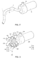
- FIG. 2 when deposits of foreign objects are suctioned by a suction pump 15 through a suction hose 17, deposits of foreign objects may not smoothly flow in a portion (r) in which the suction hose 17 is bent and may be accumulated.
- An aspect of the present disclosure may provide an apparatus for preventing blockages of foreign objects, by which a blockage phenomenon of an introduction member can be prevented by vibrating the introduction member for suctioning deposits of foreign objects.
- An aspect of the present disclosure may also provide a cleaning robot which can smoothly perform a cleaning operation by providing an introduction member of the cleaning robot with an apparatus for preventing blockages of foreign objects.
- An apparatus for preventing blockages of foreign objects includes: a support frame; an introduction member mounting unit disposed in the support frame and with which an introduction member for suctioning foreign objects is associated; and a vibration unit for vibrating the introduction member and driving the introduction member mounting unit to prevent blockages of foreign objects.
- the introduction member may be associated with the introduction member mounting unit at least to prevent twisting of the introduction member when the introduction member mounting unit is driven.
- the introduction member mounting unit may have a guide hole formed from the center of a mounting unit body toward an outer peripheral surface of the mounting unit body, allowing the introduction member to pass through the guide hole such that twisting of the introduction member is prevented as the introduction member is movable.
- the vibration unit may include: a driving member rotatably provided in the support frame and disposed on an outer peripheral surface of the introduction member mounting unit, for transferring rotational force to the introduction member mounting unit; and a driving motor for rotating the driving member.
- a first saw-tooth may be formed in the introduction member mounting unit, and a second saw-tooth corresponding to the first saw-tooth, for transferring rotational force to the introduction member mounting unit may be formed on an outer peripheral surface of the driving member.
- the vibration unit may further include a plurality of rotation support members rotatably installed in the support frame and disposed on an outer peripheral surface of the introduction member mounting unit, for rotatably supporting the introduction member mounting unit.
- the rotation support member may have a cylindrical shape, and has flanges extending outwardly from opposite ends of the cylindrical portion of the rotation support member such that the introduction member mounting unit is inserted between the flanges at the opposite ends of the rotation support member.
- a cleaning robot includes: a main frame; a travel unit mounted on the main frame, for moving the main frame; a foreign substance suction unit disposed on a movement direction side of the main frame and having a suction hole through which foreign objects are suctioned; an introduction member, one end of which is connected to the suction hole of the foreign substance suction unit and an opposite end of which is connected to a suction pump, for suctioning foreign objects; and the apparatus of any one of claims 1 to 7, which is mounted on the main frame, for vibrating the introduction member.
- FIG. 3 is a perspective view schematically illustrating an apparatus for preventing blockages of foreign objects according to an embodiment of the present disclosure.
- FIG. 4 is an exploded perspective view schematically illustrating the apparatus for preventing blockages of foreign objects according to the embodiment of the present disclosure.
- FIG. 5 is a front view schematically illustrating an apparatus for preventing blockages of foreign objects according to another embodiment of the present disclosure.
- FIG. 6 is a perspective view schematically illustrating a cleaning robot including an apparatus for preventing blockages of foreign objects according to an embodiment of the present disclosure.
- an apparatus for preventing blockages of foreign objects may include a pair of support frames 110 and 120, an introduction member mounting unit 130 rotatably arranged in the support frames 110 and 120 and with which an introduction member 270 for suctioning foreign objects are eccentrically associated, and a vibration unit 140 installed in the support frames 110 and 120, for driving the introduction member mounting unit 130 to prevent blockages of foreign objects by vibrating the introduction member 270.
- the introduction member 270 is associated with the introduction member mounting unit 130 at least to prevent twisting thereof during driving of the introduction member mounting unit 130.
- the introduction member 270 may be provided with a flexible body formed of a material such as rubber to move in response to an external impact, and although not shown, it is preferable that opposite ends of the introduction member 270 be connected to each other through a universal joint to be rotated or moved by an external force.
- a pair of support frames 110 and 120 include a front support frame 110 and a rear support frame 120. Because the front support frame 110 and the rear support frame 120 have the same shape, only the front support frame 110 will be described below.
- the front support frame 110 has a ring plate 111 having a disk shape, the center of which is hollow, and flanges 114 expanding to the opposite sides from an outer peripheral surface of the ring plate 111.
- the ring plate 111 includes a driving member coupling hole 112 into which a driving member 150 of the vibration unit 140, to be described below, is rotatably inserted to be coupled to the driving member coupling hole 112, and a rotation support member coupling hole 113 into which a pair of rotation support members 160 of the vibration member 160 are rotatably inserted to be coupled to the rotation support member coupling hole 113.
- a plurality of rotation support member coupling holes 113 corresponding to the number of rotation support members 160 instead of a pair of rotation support member coupling holes 113 may be provided such that the rotation support members 160 are installed.
- the coupling holes 112 and 113 are provided in positions having the same radius from the center of the ring plate 111, and preferably, the positions of the coupling holes 112 and 113 form an equilateral triangle. This is because the introduction member mounting unit 130, which will be described below, can be inserted between the driving member 150 and the pair of rotation support members 160 to be rotatably supported.
- the positions of the coupling holes 112 and 113 are not limited to the equilateral triangular form, and the positions of the coupling holes 112 and 113 may be arbitrarily determined as long as they can rotatably support the introduction member mounting unit 130.
- the flanges 114 are expanded to opposite sides from an outer peripheral surface of the ring plate 111, and coupling holes 115 with which the ring plate 111 is installed in the cleaning robot 200 (see FIG. 6 ), which will be described below, are provided in the flanges 114.
- the introduction member mounting unit 130 includes a mounting unit body 131 having a disk shape, and a guide hole 132 is formed from the center of the mounting unit body 131 toward an outer peripheral surface of the mounting unit body 131 such that the introduction member 270 passes through the guide hole 132, for preventing twisting.
- the mounting unit body 131 has a disk shape, and is arranged between the front support frame 110 and the rear support frame 120 to be rotatably installed. To achieve this, the mounting unit body 131 has a circular form, and an outer peripheral surface 133 of the mounting unit body 131 is adhered to the driving member 150 and the rotation support member 160 coupled to the support frames 110 and 120 such that the mounting unit body 131 is rotatably supported by the driving member 150 and the rotation support member 160.
- the guide hole 132 of the introduction member mounting unit 130 is formed to be eccentric from the center of the mounting unit body 131 toward one side of the outer peripheral surface of the mounting unit body 131, and the introduction member 270 is inserted into the guide hole 132. It is preferable that the guide hole 132 has a size sufficient to allow the introduction member 270 to be inserted into the guide hole 132 to be moved. Here, the introduction member 270 is inserted to be located on an outer peripheral surface of the guide hole 132.
- the introduction member 270 is inserted into the guide hole 132, and if the mounting unit body 131 is rotated, the introduction member 270 is linearly moved in the guide hole 132. That is, the introduction member 270 is located on the outer peripheral surface of the guide hole 132, and then is moved ward the center of the guide hole 132 as the mounting unit body 131 is rotated.
- the shape of the guide hole is not limited thereto, but may has a form in which the introduction member may be inserted into the guide hole to be fixed such that the guide hole is located eccentrically from the center of the mounting unit body toward one side of the outer peripheral surface of the mounting unit body.
- the body of the mounting unit of the introduction member is not rotated by 360 degrees but only within a predetermined angle and the introduction member inserted into the guide hole vibrates while drawing an arc upwards and downwards.
- the introduction member mounting unit may be manufactured such that the thickness of the mounting unit body is thin for light weight, may have a punched portion, and may be manufactured such that a cross-section taken along the center of the mounting unit body has a U shape.
- the vibration unit 140 includes a driving member 150 rotatably installed between the front support frame 110 and the rear support frame 120 and adhered to an outer peripheral surface 133 of the introduction member mounting unit 130, for transferring rotational force to the introduction member mounting unit 130, a driving motor 170 for rotating the driving member 150, and a plurality of rotation support members 160 rotatably installed between the front support frame 110 and the rear support frame 120 and adhered to the outer peripheral surface of the introduction member mounting unit 130, for supporting the introduction member mounting unit 130 such that the introduction member mounting unit 130 is rotated.
- a driving member 150 rotatably installed between the front support frame 110 and the rear support frame 120 and adhered to an outer peripheral surface 133 of the introduction member mounting unit 130, for transferring rotational force to the introduction member mounting unit 130
- a driving motor 170 for rotating the driving member 150
- a plurality of rotation support members 160 rotatably installed between the front support frame 110 and the rear support frame 120 and adhered to the outer peripheral surface of the introduction member mounting unit 130, for supporting the introduction member mounting
- the driving member 150 has a cylindrical shape, and has a support hole 151 coupled to the support frames 110 and 120, and a pair of flanges 152 opposite ends of which are expanded outwards.
- the driving member 150 is arranged between the driving member coupling hole 112 of the front frame 110 and the coupling hole 122 of the rear frame 120 such that the support hole 151 of the driving member 150 has the same central axis as the driving member coupling hole 112 of the front frame 110 and the coupling hole 122 of the rear frame 120.
- a rod 172 of the driving motor 170 which will be described below, is inserted into the holes 112, 122, and 151, and the driving member 150 is coupled to the rod 172 to be rotated in conjunction with the rotation of the rod 172.
- the driving member 150 is coupled to the rod 172 such that it can directly transfer rotational force of the rod 172.
- a hole is provided in the rod and a hole is also formed in the driving member inserted into the rod at a position corresponding to the hole of the rod such that a pin may be integrally inserted into the hole of the rod and the hole of the driving member to be fixed.
- a method of fixing the driving member to the rod is not limited thereto, but various mechanical coupling methods may be applied.
- the introduction member mounting unit 130 is inserted between the pair of flanges 152 of the driving member 150 to prevent the introduction member mounting unit 130 from being separated in the direction of the rotational axis, and the introduction member 130 is also rotated as the outer peripheral surface 133 of the introduction member mounting unit is adhered to the outer peripheral surface 153 of the driving member and the driving member 150 is rotated.
- the driving member 150 is rotatably installed between the driving member coupling holes 112 and 122 of the support frames 110 and 120, and is rotated by driving of the driving motor 170 such that the introduction member mounting unit 130 adhered to the outer peripheral surface 153 of the driving member is rotated.
- a driving member 150a in another embodiment in which a driving member rotates an introduction member mounting unit, includes a support hole 151a inserted into and coupled to the rod 172 of the driving motor 170, and a first saw-tooth 153a protruding from an outer peripheral surface 152a of the driving member 150a.
- An introduction member mounting unit 130a includes a mounting unit body 131a having a disk shape, a guide hole 132a formed from the center of the mounting unit body 131a toward an outer peripheral surface of the mounting unit body 131a such that the introduction member 270 is inserted into the guide hole 132a to be moved, and a second saw-tooth 133a corresponding to the first tooth 153a of the driving member 150a.
- a configuration for rotating the introduction member mounting unit by the driving member is not limited thereto, but the introduction member mounting unit may be driven by various mechanical driving methods.
- the rotation support member 160 has a cylindrical shape, and has a support hole 161 coupled to the support frames 110 and 120, and a pair of flanges 162 opposite ends of which are expanded outwards.
- the rotation support member 160 is arranged between the rotation support member coupling hole 113 of the front frame 110 and the coupling hole 123 of the rear frame 120 such that the support hole 160 of the rotation support member 161 has the same central axis as the rotation support member coupling hole 113 of the front frame 110 and the coupling hole 123 of the rear frame 120.
- a support pin 180 is inserted into the holes 113, 123, and 161, and the rotation support member 160 is installed to be rotated by the support pin 180.
- a pair of left and right rotation support members 160 are located in opposite areas of the driving member 150 with respect to a line crossing the central axes of the support frame 110 and 120, so that the introduction member mounting unit 130 may be supported by the rotation support members 160 while being located on the central axes of the support frames 110 and 120.
- the introduction member mounting unit 130 is inserted between the pair of flanges 162 of the rotation support member 160 to prevent the introduction member mounting unit 130 from being separated in the direction of the rotational axis, and an outer peripheral surface 133 of the introduction member mounting unit 130 is supported by an outer peripheral surface 163 of the rotation support member 160 such that the rotation support member 160 supports the introduction member mounting unit 130 while being rotated as the introduction member mounting unit 130 is rotated.
- the introduction member 270 inserted into the guide hole 132 may be moved in the guide hole 132 without being twisted even if the introduction member mounting unit 130 is rotated.
- the driving motor 170 includes a rod 172 protruding in a cylindrical shape, for transferring rotational force of the driving motor 170, and a boss 174 inserted into a motor coupling unit 125 provided in the rear support frame 120. If necessary, the driving motor 170 may further include a reducer 173.
- the driving motor 170 may be a motor in circulation, and it is preferable that the motor is a waterproof motor such that it may be used under the water.
- the configuration for coupling the driving motor 170 to the rear support frame 120 is not limited thereto, but various mechanical coupling methods may be applied.
- FIG. 6 is a perspective view schematically illustrating a cleaning robot including an apparatus for preventing blockages of foreign objects according to an embodiment of the present disclosure.
- the cleaning robot 200 includes a main frame 210, a travel unit 240 mounted on the main frame 210, for moving the main frame 210, a foreign substance suction unit 260 disposed on a movement side of the main frame 210 and including a suction hole 261 through which foreign objects are suctioned, an introduction member 270 one end of which is connected to the suction hole 261 of the foreign substance suction unit 260 and an opposite end of which is connected to a suction pump 250, for suctioning foreign objects, and a foreign substance blockage prevention unit 100 mounted on the main frame 210, for vibrating the introduction member 270.
- the main frame 210 may be provided such that a plurality of support beams for supporting the travel unit 240 and the foreign substance suction unit 260 are coupled to each other, and may generally have rectangular parallelepiped shape in the embodiment of the present disclosure.
- the travel unit 240 is mounted on a lower end of the main frame 210, and wheels may be arranged in the travel unit 240 such that the travel unit 210 may move forwards and rearwards or may be provided in a screw form for breaking up deposits of foreign objects on the bottom while being rotated in a vertical direction of a progress direction and moving the main frame 210.
- the foreign substance suction unit 260 is arranged such that the main frame 210 is mounted on a front movement direction side of the foreign substance suction unit 260 and the foreign substance suction unit 260 suctions and removes foreign objects prevent in a movement direction of the main frame 210.
- the foreign substance suction unit 260 includes a rotary screw 262 for breaking up deposited foreign objects, and a suction hole 261 for suctioning the shattered foreign objects.
- the introduction member 270 is connected to a suction hole 261 of the foreign substance suction unit 260 and an opposite end thereof is connected to the suction pump 250. If the suction pump 250 is driven, foreign objects are suctioned through the introduction member 270 by a suction force of the suction pump 250, and the suctioned foreign objects are discharged to the outside through a discharge hose 280.
- the introduction member 270 has a flexible body formed of a material such as rubber to move in response to an external force.
- the foreign substance blockage prevention unit 100 includes support frames 110 and 120 installed in the main frame 210, an introduction member mounting unit 130 into which the introduction member 270 is eccentrically inserted, a driving member 150 for rotating the introduction member mounting unit 130, a rotation support member 160 supporting the introduction member mounting unit 130 such that the introduction member mounting unit 130 may be rotated, and a driving motor 170 for driving the driving member 150.
- the travel unit 240, the suction pump 250, and the driving motor 170 of the foreign substance blockage prevention unit 100 are provided with power and the power is controlled by a power generating unit 220 and a control unit 230
- foreign objects are suctioned by the foreign substance suction unit 260 while the cleaning robot 200 moves in a space, such as a water tank, in which foreign objects are deposited, and the introduction member 270 eccentrically inserted into the introduction member mounting unit 130 is vibrated upward and downwards by rotation of the introduction member mounting unit 130 so that a phenomenon in which foreign objects are deposited in the introduction member 270 can be prevented.
- the shape of the cleaning robot is not limited thereto, but any shape by which a flexible introduction member for suctioning foreign objects are provided may be applied.
- a problem of applying an overload to a suction pump is solved by preventing a breakage phenomenon of a hose, making it possible to prevent a breakdown of a pump and reduce power consumption.
- a cleaning robot can be operated without stopping by applying the apparatus for preventing breakage of foreign objects to a cleaning robot, cleaning efficiency of a water tank can be improved.
Landscapes
- Engineering & Computer Science (AREA)
- Mechanical Engineering (AREA)
- Manipulator (AREA)
- Cleaning In General (AREA)
Abstract
Description
- This application claims the benefit of Korean Patent Application No.
10-2014-0090883 filed on July 18, 2014 - The present disclosure relates to an apparatus for preventing blockages of foreign objects and a cleaning robot including the same, and more particularly, to an apparatus for preventing blockages of foreign objects, by which a blocking phenomenon can be prevented while deposits of foreign objects are suctioned, and a cleaning robot including the same.
- In steel mills, various types of water tanks are used, including water tanks for storing water used when steel is manufactured and water tanks for storing water used as cooling water and or water to be mixed with various substances to form waste sludge. However, because it is difficult to circulate and reuse water in a water tank, and foreign objects contained in sludge may be indrawn by a underwater pump, causing a the underwater pump to malfunction if deposits of foreign objects such as sludge are formed in the interior of the water tank, such deposits of foreign objects in the water tank should be removed regularly.
- In recent years, a cleaning robot based on an automatic underwater travel system, by which deposits of foreign objects in a water tank can be removed while equipment operations are maintained, is introduced into the water tank to suction deposits of foreign objects while moving within in the water tank.
-
FIG. 1 is a view schematically illustrating a cleaning robot based on an underwater automatic travel system. Referring toFIG. 1 , in thecleaning robot 10, anunderground suction pump 15 generates suction pressure and asuction module 16 breaks up deposits of foreign objects and suctions and discharges sludge deposits of foreign objects. However, the deposits of foreign objects are not always uniformly suctioned but a large amount of deposits of foreign objects are suctioned at a time in a process of suctioning the deposits of foreign objects, frequently causing a phenomenon of blocking the suctioned deposits of foreign objects in the interior of asuction hose 17. In particular, referring toFIG. 2 , when deposits of foreign objects are suctioned by asuction pump 15 through asuction hose 17, deposits of foreign objects may not smoothly flow in a portion (r) in which thesuction hose 17 is bent and may be accumulated. - In this way, because a high pressure is applied to an underground pump as a load if the suction hose is blocked such that water and deposits of foreign objects cannot smoothly flow, a large amount of currents are consumed for the suction pump.
- Further, when a suction strength of a suction pump is limited for safety, such that the pump is automatically stopped when a predetermined volume of fluid or higher is drawn in thereby, an operation of a cleaning robot is stopped if such a phenomenon occurs frequently during the operation of the cleaning robot, making it impossible to perform a deposit cleaning operation, and therefore rapidly lowering cleaning efficiency.
- An aspect of the present disclosure may provide an apparatus for preventing blockages of foreign objects, by which a blockage phenomenon of an introduction member can be prevented by vibrating the introduction member for suctioning deposits of foreign objects.
- An aspect of the present disclosure may also provide a cleaning robot which can smoothly perform a cleaning operation by providing an introduction member of the cleaning robot with an apparatus for preventing blockages of foreign objects.
- According to an aspect of the present disclosure, An apparatus for preventing blockages of foreign objects, includes: a support frame; an introduction member mounting unit disposed in the support frame and with which an introduction member for suctioning foreign objects is associated; and a vibration unit for vibrating the introduction member and driving the introduction member mounting unit to prevent blockages of foreign objects.
- The introduction member may be associated with the introduction member mounting unit at least to prevent twisting of the introduction member when the introduction member mounting unit is driven.
- The introduction member mounting unit may have a guide hole formed from the center of a mounting unit body toward an outer peripheral surface of the mounting unit body, allowing the introduction member to pass through the guide hole such that twisting of the introduction member is prevented as the introduction member is movable.
- The vibration unit may include: a driving member rotatably provided in the support frame and disposed on an outer peripheral surface of the introduction member mounting unit, for transferring rotational force to the introduction member mounting unit; and a driving motor for rotating the driving member.
- A first saw-tooth may be formed in the introduction member mounting unit, and a second saw-tooth corresponding to the first saw-tooth, for transferring rotational force to the introduction member mounting unit may be formed on an outer peripheral surface of the driving member.
- The vibration unit may further include a plurality of rotation support members rotatably installed in the support frame and disposed on an outer peripheral surface of the introduction member mounting unit, for rotatably supporting the introduction member mounting unit.
- The rotation support member may have a cylindrical shape, and has flanges extending outwardly from opposite ends of the cylindrical portion of the rotation support member such that the introduction member mounting unit is inserted between the flanges at the opposite ends of the rotation support member.
- According to another aspect of the present disclosure, a cleaning robot includes: a main frame; a travel unit mounted on the main frame, for moving the main frame; a foreign substance suction unit disposed on a movement direction side of the main frame and having a suction hole through which foreign objects are suctioned; an introduction member, one end of which is connected to the suction hole of the foreign substance suction unit and an opposite end of which is connected to a suction pump, for suctioning foreign objects; and the apparatus of any one of claims 1 to 7, which is mounted on the main frame, for vibrating the introduction member.
- The above and other aspects, features and other advantages of the present disclosure will be more clearly understood from the following detailed description taken in conjunction with the accompanying drawings, in which:
-
FIG. 1 is a perspective view schematically illustrating a cleaning robot according to the related art; -
FIG. 2 is a perspective view schematically illustrating a main part extracted from the cleaning robot according to the related art; -
FIG. 3 is a perspective view schematically illustrating an apparatus for preventing blockages of foreign objects according to an embodiment of the present disclosure; -
FIG. 4 is an exploded perspective view schematically illustrating the apparatus for preventing blockages of foreign objects according to the embodiment of the present disclosure; -
FIG. 5 is a front view schematically illustrating an apparatus for preventing blockages of foreign objects according to another embodiment of the present disclosure; and -
FIG. 6 is a perspective view schematically illustrating a cleaning robot including an apparatus for preventing blockages of foreign objects according to an embodiment of the present disclosure. - In order to help understanding of features of the present disclosure, an apparatus for preventing blockages of foreign objects and a cleaning robot including the same according to exemplary embodiments of the present disclosure will be described below in detail.
- It is to be noted that, when reference numerals are given to the constituent elements of the accompanying drawings to help understanding of the embodiments of the present disclosure, the same constituent elements are denoted by the same reference numerals if possible even if they are shown in different drawings. Further, in the following description of the present disclosure, a detailed description of known functions and configurations incorporated herein will be omitted when it may make the subject matter of the present disclosure rather unclear.
- Hereinafter, the detailed embodiments of the present disclosure will be described with reference to the accompanying drawings.
-
FIG. 3 is a perspective view schematically illustrating an apparatus for preventing blockages of foreign objects according to an embodiment of the present disclosure.FIG. 4 is an exploded perspective view schematically illustrating the apparatus for preventing blockages of foreign objects according to the embodiment of the present disclosure.FIG. 5 is a front view schematically illustrating an apparatus for preventing blockages of foreign objects according to another embodiment of the present disclosure.FIG. 6 is a perspective view schematically illustrating a cleaning robot including an apparatus for preventing blockages of foreign objects according to an embodiment of the present disclosure. - Referring to
FIGS. 3 to 5 , an apparatus for preventing blockages of foreign objects according to an embodiment of the present disclosure may include a pair ofsupport frames member mounting unit 130 rotatably arranged in thesupport frames introduction member 270 for suctioning foreign objects are eccentrically associated, and a vibration unit 140 installed in thesupport frames member mounting unit 130 to prevent blockages of foreign objects by vibrating theintroduction member 270. - The
introduction member 270 is associated with the introductionmember mounting unit 130 at least to prevent twisting thereof during driving of the introductionmember mounting unit 130. Here, theintroduction member 270 may be provided with a flexible body formed of a material such as rubber to move in response to an external impact, and although not shown, it is preferable that opposite ends of theintroduction member 270 be connected to each other through a universal joint to be rotated or moved by an external force. - A pair of
support frames front support frame 110 and arear support frame 120. Because thefront support frame 110 and therear support frame 120 have the same shape, only thefront support frame 110 will be described below. - The
front support frame 110 has aring plate 111 having a disk shape, the center of which is hollow, and flanges 114 expanding to the opposite sides from an outer peripheral surface of thering plate 111. - The
ring plate 111 includes a drivingmember coupling hole 112 into which adriving member 150 of the vibration unit 140, to be described below, is rotatably inserted to be coupled to the drivingmember coupling hole 112, and a rotation supportmember coupling hole 113 into which a pair ofrotation support members 160 of thevibration member 160 are rotatably inserted to be coupled to the rotation supportmember coupling hole 113. Of course, a plurality of rotation supportmember coupling holes 113 corresponding to the number ofrotation support members 160 instead of a pair of rotation supportmember coupling holes 113 may be provided such that therotation support members 160 are installed. - The
coupling holes ring plate 111, and preferably, the positions of thecoupling holes member mounting unit 130, which will be described below, can be inserted between thedriving member 150 and the pair ofrotation support members 160 to be rotatably supported. Of course, the positions of thecoupling holes coupling holes member mounting unit 130. - The flanges 114 are expanded to opposite sides from an outer peripheral surface of the
ring plate 111, andcoupling holes 115 with which thering plate 111 is installed in the cleaning robot 200 (seeFIG. 6 ), which will be described below, are provided in the flanges 114. - The introduction
member mounting unit 130 includes amounting unit body 131 having a disk shape, and aguide hole 132 is formed from the center of themounting unit body 131 toward an outer peripheral surface of themounting unit body 131 such that theintroduction member 270 passes through theguide hole 132, for preventing twisting. - The
mounting unit body 131 has a disk shape, and is arranged between thefront support frame 110 and therear support frame 120 to be rotatably installed. To achieve this, themounting unit body 131 has a circular form, and an outerperipheral surface 133 of themounting unit body 131 is adhered to thedriving member 150 and therotation support member 160 coupled to thesupport frames mounting unit body 131 is rotatably supported by thedriving member 150 and therotation support member 160. - The
guide hole 132 of the introductionmember mounting unit 130 is formed to be eccentric from the center of themounting unit body 131 toward one side of the outer peripheral surface of themounting unit body 131, and theintroduction member 270 is inserted into theguide hole 132. It is preferable that theguide hole 132 has a size sufficient to allow theintroduction member 270 to be inserted into theguide hole 132 to be moved. Here, theintroduction member 270 is inserted to be located on an outer peripheral surface of theguide hole 132. - With the construction, the
introduction member 270 is inserted into theguide hole 132, and if themounting unit body 131 is rotated, theintroduction member 270 is linearly moved in theguide hole 132. That is, theintroduction member 270 is located on the outer peripheral surface of theguide hole 132, and then is moved ward the center of theguide hole 132 as themounting unit body 131 is rotated. - Of course, the shape of the guide hole is not limited thereto, but may has a form in which the introduction member may be inserted into the guide hole to be fixed such that the guide hole is located eccentrically from the center of the mounting unit body toward one side of the outer peripheral surface of the mounting unit body. With the guide hole, the body of the mounting unit of the introduction member is not rotated by 360 degrees but only within a predetermined angle and the introduction member inserted into the guide hole vibrates while drawing an arc upwards and downwards.
- The introduction member mounting unit may be manufactured such that the thickness of the mounting unit body is thin for light weight, may have a punched portion, and may be manufactured such that a cross-section taken along the center of the mounting unit body has a U shape.
- The vibration unit 140 includes a
driving member 150 rotatably installed between thefront support frame 110 and therear support frame 120 and adhered to an outerperipheral surface 133 of the introductionmember mounting unit 130, for transferring rotational force to the introductionmember mounting unit 130, adriving motor 170 for rotating thedriving member 150, and a plurality ofrotation support members 160 rotatably installed between thefront support frame 110 and therear support frame 120 and adhered to the outer peripheral surface of the introductionmember mounting unit 130, for supporting the introductionmember mounting unit 130 such that the introductionmember mounting unit 130 is rotated. - The driving
member 150 has a cylindrical shape, and has asupport hole 151 coupled to the support frames 110 and 120, and a pair offlanges 152 opposite ends of which are expanded outwards. - The driving
member 150 is arranged between the drivingmember coupling hole 112 of thefront frame 110 and thecoupling hole 122 of therear frame 120 such that thesupport hole 151 of the drivingmember 150 has the same central axis as the drivingmember coupling hole 112 of thefront frame 110 and thecoupling hole 122 of therear frame 120. Arod 172 of the drivingmotor 170, which will be described below, is inserted into theholes member 150 is coupled to therod 172 to be rotated in conjunction with the rotation of therod 172. - It is preferable that the driving
member 150 is coupled to therod 172 such that it can directly transfer rotational force of therod 172. For example, although not shown, a hole is provided in the rod and a hole is also formed in the driving member inserted into the rod at a position corresponding to the hole of the rod such that a pin may be integrally inserted into the hole of the rod and the hole of the driving member to be fixed. Of course, a method of fixing the driving member to the rod is not limited thereto, but various mechanical coupling methods may be applied. - The introduction
member mounting unit 130 is inserted between the pair offlanges 152 of the drivingmember 150 to prevent the introductionmember mounting unit 130 from being separated in the direction of the rotational axis, and theintroduction member 130 is also rotated as the outerperipheral surface 133 of the introduction member mounting unit is adhered to the outerperipheral surface 153 of the driving member and the drivingmember 150 is rotated. - With the construction, the driving
member 150 is rotatably installed between the driving member coupling holes 112 and 122 of the support frames 110 and 120, and is rotated by driving of the drivingmotor 170 such that the introductionmember mounting unit 130 adhered to the outerperipheral surface 153 of the driving member is rotated. - Referring to
FIG. 5 , in another embodiment in which a driving member rotates an introduction member mounting unit, a drivingmember 150a includes asupport hole 151a inserted into and coupled to therod 172 of the drivingmotor 170, and a first saw-tooth 153a protruding from an outerperipheral surface 152a of the drivingmember 150a. An introductionmember mounting unit 130a includes a mountingunit body 131a having a disk shape, aguide hole 132a formed from the center of the mountingunit body 131a toward an outer peripheral surface of the mountingunit body 131a such that theintroduction member 270 is inserted into theguide hole 132a to be moved, and a second saw-tooth 133a corresponding to thefirst tooth 153a of the drivingmember 150a. With the construction, rotational force of the drivingmember 150a can be transferred to the introductionmember mounting unit 130a more precisely and more efficiently. - Of course, a configuration for rotating the introduction member mounting unit by the driving member is not limited thereto, but the introduction member mounting unit may be driven by various mechanical driving methods.
- The
rotation support member 160 has a cylindrical shape, and has asupport hole 161 coupled to the support frames 110 and 120, and a pair offlanges 162 opposite ends of which are expanded outwards. - The
rotation support member 160 is arranged between the rotation supportmember coupling hole 113 of thefront frame 110 and thecoupling hole 123 of therear frame 120 such that thesupport hole 160 of therotation support member 161 has the same central axis as the rotation supportmember coupling hole 113 of thefront frame 110 and thecoupling hole 123 of therear frame 120. Asupport pin 180 is inserted into theholes rotation support member 160 is installed to be rotated by thesupport pin 180. A pair of left and rightrotation support members 160 are located in opposite areas of the drivingmember 150 with respect to a line crossing the central axes of thesupport frame member mounting unit 130 may be supported by therotation support members 160 while being located on the central axes of the support frames 110 and 120. - The introduction
member mounting unit 130 is inserted between the pair offlanges 162 of therotation support member 160 to prevent the introductionmember mounting unit 130 from being separated in the direction of the rotational axis, and an outerperipheral surface 133 of the introductionmember mounting unit 130 is supported by an outerperipheral surface 163 of therotation support member 160 such that therotation support member 160 supports the introductionmember mounting unit 130 while being rotated as the introductionmember mounting unit 130 is rotated. - With the construction, the
introduction member 270 inserted into theguide hole 132 may be moved in theguide hole 132 without being twisted even if the introductionmember mounting unit 130 is rotated. - The driving
motor 170 includes arod 172 protruding in a cylindrical shape, for transferring rotational force of the drivingmotor 170, and aboss 174 inserted into amotor coupling unit 125 provided in therear support frame 120. If necessary, the drivingmotor 170 may further include areducer 173. The drivingmotor 170 may be a motor in circulation, and it is preferable that the motor is a waterproof motor such that it may be used under the water. The configuration for coupling the drivingmotor 170 to therear support frame 120 is not limited thereto, but various mechanical coupling methods may be applied. -
FIG. 6 is a perspective view schematically illustrating a cleaning robot including an apparatus for preventing blockages of foreign objects according to an embodiment of the present disclosure. - Referring to
FIG. 6 , the cleaningrobot 200 according to the present disclosure includes amain frame 210, atravel unit 240 mounted on themain frame 210, for moving themain frame 210, a foreignsubstance suction unit 260 disposed on a movement side of themain frame 210 and including asuction hole 261 through which foreign objects are suctioned, anintroduction member 270 one end of which is connected to thesuction hole 261 of the foreignsubstance suction unit 260 and an opposite end of which is connected to asuction pump 250, for suctioning foreign objects, and a foreign substanceblockage prevention unit 100 mounted on themain frame 210, for vibrating theintroduction member 270. - The
main frame 210 may be provided such that a plurality of support beams for supporting thetravel unit 240 and the foreignsubstance suction unit 260 are coupled to each other, and may generally have rectangular parallelepiped shape in the embodiment of the present disclosure. - The
travel unit 240 is mounted on a lower end of themain frame 210, and wheels may be arranged in thetravel unit 240 such that thetravel unit 210 may move forwards and rearwards or may be provided in a screw form for breaking up deposits of foreign objects on the bottom while being rotated in a vertical direction of a progress direction and moving themain frame 210. - The foreign
substance suction unit 260 is arranged such that themain frame 210 is mounted on a front movement direction side of the foreignsubstance suction unit 260 and the foreignsubstance suction unit 260 suctions and removes foreign objects prevent in a movement direction of themain frame 210. The foreignsubstance suction unit 260 includes a rotary screw 262 for breaking up deposited foreign objects, and asuction hole 261 for suctioning the shattered foreign objects. - One end of the
introduction member 270 is connected to asuction hole 261 of the foreignsubstance suction unit 260 and an opposite end thereof is connected to thesuction pump 250. If thesuction pump 250 is driven, foreign objects are suctioned through theintroduction member 270 by a suction force of thesuction pump 250, and the suctioned foreign objects are discharged to the outside through adischarge hose 280. Here, it is preferable that theintroduction member 270 has a flexible body formed of a material such as rubber to move in response to an external force. - The foreign substance
blockage prevention unit 100 includes support frames 110 and 120 installed in themain frame 210, an introductionmember mounting unit 130 into which theintroduction member 270 is eccentrically inserted, a drivingmember 150 for rotating the introductionmember mounting unit 130, arotation support member 160 supporting the introductionmember mounting unit 130 such that the introductionmember mounting unit 130 may be rotated, and a drivingmotor 170 for driving the drivingmember 150. - The
travel unit 240, thesuction pump 250, and the drivingmotor 170 of the foreign substanceblockage prevention unit 100 are provided with power and the power is controlled by apower generating unit 220 and acontrol unit 230 - With the construction, foreign objects are suctioned by the foreign
substance suction unit 260 while thecleaning robot 200 moves in a space, such as a water tank, in which foreign objects are deposited, and theintroduction member 270 eccentrically inserted into the introductionmember mounting unit 130 is vibrated upward and downwards by rotation of the introductionmember mounting unit 130 so that a phenomenon in which foreign objects are deposited in theintroduction member 270 can be prevented. - Of course, the shape of the cleaning robot is not limited thereto, but any shape by which a flexible introduction member for suctioning foreign objects are provided may be applied.
- In accordance with the apparatus for preventing blockages of foreign objects according to the present disclosure, a problem of applying an overload to a suction pump is solved by preventing a breakage phenomenon of a hose, making it possible to prevent a breakdown of a pump and reduce power consumption.
- According to the present disclosure, because a cleaning robot can be operated without stopping by applying the apparatus for preventing breakage of foreign objects to a cleaning robot, cleaning efficiency of a water tank can be improved.
- Although the prevent invention has been described with reference to its embodiments and drawings until now, the present disclosure is not limited thereto and it is noted that the present disclosure may be variously corrected and modified by those skilled in the art to which the present disclosure pertains within the technical spirit of the present disclosure and the equivalents of the claims, which will be described below.
Claims (8)
- An apparatus for preventing blockages of foreign objects, the apparatus comprising:a support frame;an introduction member mounting unit disposed in the support frame and with which an introduction member for suctioning foreign objects is associated; anda vibration unit for vibrating the introduction member and driving the introduction member mounting unit to prevent blockages of foreign objects.
- The apparatus of claim 1, wherein the introduction member is associated with the introduction member mounting unit at least to prevent twisting of the introduction member when the introduction member mounting unit is driven.
- The apparatus of claim 2, wherein the introduction member mounting unit has a guide hole formed from the center of a mounting unit body toward an outer peripheral surface of the mounting unit body, allowing the introduction member to pass through the guide hole such that twisting of the introduction member is prevented as the introduction member is movable.
- The apparatus of claim 3, wherein the vibration unit comprises:a driving member rotatably provided in the support frame and disposed on an outer peripheral surface of the introduction member mounting unit, for transferring rotational force to the introduction member mounting unit; anda driving motor for rotating the driving member.
- The apparatus of claim 4, wherein a first saw-tooth is formed in the introduction member mounting unit, and a second saw-tooth corresponding to the first saw-tooth, for transferring rotational force to the introduction member mounting unit is formed on an outer peripheral surface of the driving member.
- The apparatus of claim 4, wherein the vibration unit further comprises a plurality of rotation support members rotatably installed in the support frame and disposed on an outer peripheral surface of the introduction member mounting unit, for rotatably supporting the introduction member mounting unit.
- The apparatus of claim 6, wherein the rotation support member has a cylindrical shape, and has flanges extending outwardly from opposite ends of the cylindrical portion of the rotation support member such that the introduction member mounting unit is inserted between the flanges at the opposite ends of the rotation support member.
- A cleaning robot comprising:a main frame;a travel unit mounted on the main frame, for moving the main frame;a foreign substance suction unit disposed on a movement direction side of the main frame and having a suction hole through which foreign objects are suctioned;an introduction member, one end of which is connected to the suction hole of the foreign substance suction unit and an opposite end of which is connected to a suction pump, for suctioning foreign objects; andthe apparatus of any one of claims 1 to 7, which is mounted on the main frame, for vibrating the introduction member.
Applications Claiming Priority (1)
| Application Number | Priority Date | Filing Date | Title |
|---|---|---|---|
| KR1020140090883A KR101620698B1 (en) | 2014-07-18 | 2014-07-18 | Apparatus for blockage prevention and robot for cleaning sludge including the same |
Publications (1)
| Publication Number | Publication Date |
|---|---|
| EP2974805A1 true EP2974805A1 (en) | 2016-01-20 |
Family
ID=52396630
Family Applications (1)
| Application Number | Title | Priority Date | Filing Date |
|---|---|---|---|
| EP15275018.8A Withdrawn EP2974805A1 (en) | 2014-07-18 | 2015-01-15 | Apparatus for preventing blockages of foreign objects and cleaning robot including the same |
Country Status (3)
| Country | Link |
|---|---|
| EP (1) | EP2974805A1 (en) |
| KR (1) | KR101620698B1 (en) |
| CN (1) | CN105268704B (en) |
Cited By (1)
| Publication number | Priority date | Publication date | Assignee | Title |
|---|---|---|---|---|
| CN107716506A (en) * | 2017-09-29 | 2018-02-23 | 神华集团有限责任公司 | Liquid outlet anti-blocking method and liquid outlet anti-block apparatus |
Families Citing this family (2)
| Publication number | Priority date | Publication date | Assignee | Title |
|---|---|---|---|---|
| KR102178742B1 (en) * | 2018-11-29 | 2020-11-16 | 주식회사 포스코 | An apparatus for controlling a cleaning robot and a control method for the same |
| KR102925460B1 (en) | 2021-12-09 | 2026-02-11 | 주식회사 엘엑스세미콘 | Clock data recovery circuit for display and clock recovery circuit thereof |
Citations (5)
| Publication number | Priority date | Publication date | Assignee | Title |
|---|---|---|---|---|
| GB969801A (en) * | 1962-04-11 | 1964-09-16 | Bristol Siddeley Engines Ltd | An improved method and apparatus for cleaning the interior of a flexible pipe |
| JPH04272340A (en) * | 1991-02-28 | 1992-09-29 | Kyokuto Kaihatsu Kogyo Co Ltd | Suction pipe structure for hose handling device |
| US20050108848A1 (en) * | 2003-11-25 | 2005-05-26 | Buckner Don M. | Vacuum hose wobbler |
| WO2012023676A1 (en) * | 2010-08-20 | 2012-02-23 | Pohang Institute Of Intelligent Robotics | Cleaning robot and underwater sediment cleaning apparatus and method |
| CN103708231A (en) * | 2013-12-23 | 2014-04-09 | 江苏大学 | Anti-blocking method and device for pebble coal vacuum transport system |
Family Cites Families (3)
| Publication number | Priority date | Publication date | Assignee | Title |
|---|---|---|---|---|
| DE3714578A1 (en) * | 1986-05-09 | 1987-11-12 | Walter Mooser | Process and device for disintegrating pipe blockages |
| JPH05164300A (en) * | 1991-12-13 | 1993-06-29 | Hitachi Ltd | Piping system |
| CN201517779U (en) * | 2009-02-24 | 2010-06-30 | 莫燕 | Vibrating and dredging coal chute |
-
2014
- 2014-07-18 KR KR1020140090883A patent/KR101620698B1/en active Active
-
2015
- 2015-01-15 EP EP15275018.8A patent/EP2974805A1/en not_active Withdrawn
- 2015-01-27 CN CN201510040909.4A patent/CN105268704B/en not_active Expired - Fee Related
Patent Citations (5)
| Publication number | Priority date | Publication date | Assignee | Title |
|---|---|---|---|---|
| GB969801A (en) * | 1962-04-11 | 1964-09-16 | Bristol Siddeley Engines Ltd | An improved method and apparatus for cleaning the interior of a flexible pipe |
| JPH04272340A (en) * | 1991-02-28 | 1992-09-29 | Kyokuto Kaihatsu Kogyo Co Ltd | Suction pipe structure for hose handling device |
| US20050108848A1 (en) * | 2003-11-25 | 2005-05-26 | Buckner Don M. | Vacuum hose wobbler |
| WO2012023676A1 (en) * | 2010-08-20 | 2012-02-23 | Pohang Institute Of Intelligent Robotics | Cleaning robot and underwater sediment cleaning apparatus and method |
| CN103708231A (en) * | 2013-12-23 | 2014-04-09 | 江苏大学 | Anti-blocking method and device for pebble coal vacuum transport system |
Non-Patent Citations (1)
| Title |
|---|
| DATABASE WPI Section PQ Week 201435, Derwent World Patents Index; Class Q35, AN 2014-K53225, XP002750762 * |
Cited By (1)
| Publication number | Priority date | Publication date | Assignee | Title |
|---|---|---|---|---|
| CN107716506A (en) * | 2017-09-29 | 2018-02-23 | 神华集团有限责任公司 | Liquid outlet anti-blocking method and liquid outlet anti-block apparatus |
Also Published As
| Publication number | Publication date |
|---|---|
| KR101620698B1 (en) | 2016-05-13 |
| KR20160010784A (en) | 2016-01-28 |
| CN105268704A (en) | 2016-01-27 |
| CN105268704B (en) | 2017-11-10 |
Similar Documents
| Publication | Publication Date | Title |
|---|---|---|
| EP2481461B1 (en) | Filtering apparatus for ballast water treatment | |
| EP1457244B1 (en) | Filter device | |
| US9975155B2 (en) | Cleaner | |
| KR101231644B1 (en) | Magnetic separation apparatus | |
| KR101620698B1 (en) | Apparatus for blockage prevention and robot for cleaning sludge including the same | |
| JP6421106B2 (en) | Cleaning device for heat exchanger of ceiling-mounted air conditioner | |
| GB2507438A (en) | Water filter | |
| CN114215141B (en) | Water intake device for dissolved air pump | |
| CN105313298B (en) | One kind filtering die head | |
| CN108573760A (en) | A kind of underwater flusher for Spent Fuel Pool dilatation and underwater purging method | |
| EP3523256B1 (en) | Equipment for collecting and treating waste with a filtering unit and process therefor | |
| CN108371839A (en) | The sewage filter device of environmental protection | |
| CN115245898A (en) | Multistage particle size screening device and method for construction waste | |
| CN210367276U (en) | High-efficient sewage treatment plant | |
| CN109056080B (en) | Adopt preliminary belt cleaning device of livestock farm wool of centrifugal treatment | |
| CN204891363U (en) | Mud water separator | |
| JP6749822B2 (en) | Cleaning device and cleaning method for radioactive contaminant storage tank | |
| KR20190053557A (en) | Apparatus for repairing in a drain pipe | |
| KR20140005504U (en) | Slag removing apparatus | |
| CN207288536U (en) | A kind of die waste vibrates sliding mechanism | |
| EP3768432B1 (en) | Flotation machine apparatus and method of using the same | |
| CN210814773U (en) | Calcium carbonate agitating unit | |
| CN205835919U (en) | A kind of filtration die head | |
| CN222362546U (en) | Desilting equipment for mines | |
| CN220784367U (en) | Feeding equipment for electric pole production |
Legal Events
| Date | Code | Title | Description |
|---|---|---|---|
| PUAI | Public reference made under article 153(3) epc to a published international application that has entered the european phase |
Free format text: ORIGINAL CODE: 0009012 |
|
| 17P | Request for examination filed |
Effective date: 20150115 |
|
| AK | Designated contracting states |
Kind code of ref document: A1 Designated state(s): AL AT BE BG CH CY CZ DE DK EE ES FI FR GB GR HR HU IE IS IT LI LT LU LV MC MK MT NL NO PL PT RO RS SE SI SK SM TR |
|
| AX | Request for extension of the european patent |
Extension state: BA ME |
|
| STAA | Information on the status of an ep patent application or granted ep patent |
Free format text: STATUS: EXAMINATION IS IN PROGRESS |
|
| 17Q | First examination report despatched |
Effective date: 20180618 |
|
| STAA | Information on the status of an ep patent application or granted ep patent |
Free format text: STATUS: THE APPLICATION IS DEEMED TO BE WITHDRAWN |
|
| 18D | Application deemed to be withdrawn |
Effective date: 20210803 |