EP2974638A1 - Toilet seat hinge assembly - Google Patents
Toilet seat hinge assembly Download PDFInfo
- Publication number
- EP2974638A1 EP2974638A1 EP15175348.0A EP15175348A EP2974638A1 EP 2974638 A1 EP2974638 A1 EP 2974638A1 EP 15175348 A EP15175348 A EP 15175348A EP 2974638 A1 EP2974638 A1 EP 2974638A1
- Authority
- EP
- European Patent Office
- Prior art keywords
- segment
- fastener
- hinge
- toilet bowl
- hinge assembly
- Prior art date
- Legal status (The legal status is an assumption and is not a legal conclusion. Google has not performed a legal analysis and makes no representation as to the accuracy of the status listed.)
- Granted
Links
- 239000000463 material Substances 0.000 claims abstract description 10
- 239000004033 plastic Substances 0.000 claims abstract description 9
- 238000000034 method Methods 0.000 description 11
- 230000000712 assembly Effects 0.000 description 4
- 238000000429 assembly Methods 0.000 description 4
- 230000000994 depressogenic effect Effects 0.000 description 3
- 238000004891 communication Methods 0.000 description 2
- 230000008878 coupling Effects 0.000 description 2
- 238000010168 coupling process Methods 0.000 description 2
- 238000005859 coupling reaction Methods 0.000 description 2
- 230000006870 function Effects 0.000 description 2
- 239000011521 glass Substances 0.000 description 2
- 238000001746 injection moulding Methods 0.000 description 2
- 239000004677 Nylon Substances 0.000 description 1
- 239000004743 Polypropylene Substances 0.000 description 1
- 229910000831 Steel Inorganic materials 0.000 description 1
- 238000010276 construction Methods 0.000 description 1
- 229920001519 homopolymer Polymers 0.000 description 1
- 230000002401 inhibitory effect Effects 0.000 description 1
- 238000009434 installation Methods 0.000 description 1
- 239000002184 metal Substances 0.000 description 1
- 229920001778 nylon Polymers 0.000 description 1
- -1 polypropylene Polymers 0.000 description 1
- 229920001155 polypropylene Polymers 0.000 description 1
- 238000010008 shearing Methods 0.000 description 1
- 229910001220 stainless steel Inorganic materials 0.000 description 1
- 239000010935 stainless steel Substances 0.000 description 1
- 239000010959 steel Substances 0.000 description 1
- 230000007704 transition Effects 0.000 description 1
Images


Classifications
-
- A—HUMAN NECESSITIES
- A47—FURNITURE; DOMESTIC ARTICLES OR APPLIANCES; COFFEE MILLS; SPICE MILLS; SUCTION CLEANERS IN GENERAL
- A47K—SANITARY EQUIPMENT NOT OTHERWISE PROVIDED FOR; TOILET ACCESSORIES
- A47K13/00—Seats or covers for all kinds of closets
- A47K13/12—Hinges
-
- A—HUMAN NECESSITIES
- A47—FURNITURE; DOMESTIC ARTICLES OR APPLIANCES; COFFEE MILLS; SPICE MILLS; SUCTION CLEANERS IN GENERAL
- A47K—SANITARY EQUIPMENT NOT OTHERWISE PROVIDED FOR; TOILET ACCESSORIES
- A47K13/00—Seats or covers for all kinds of closets
- A47K13/24—Parts or details not covered in, or of interest apart from, groups A47K13/02 - A47K13/22, e.g. devices imparting a swinging or vibrating motion to the seats
- A47K13/26—Mounting devices for seats or covers
-
- F—MECHANICAL ENGINEERING; LIGHTING; HEATING; WEAPONS; BLASTING
- F16—ENGINEERING ELEMENTS AND UNITS; GENERAL MEASURES FOR PRODUCING AND MAINTAINING EFFECTIVE FUNCTIONING OF MACHINES OR INSTALLATIONS; THERMAL INSULATION IN GENERAL
- F16B—DEVICES FOR FASTENING OR SECURING CONSTRUCTIONAL ELEMENTS OR MACHINE PARTS TOGETHER, e.g. NAILS, BOLTS, CIRCLIPS, CLAMPS, CLIPS OR WEDGES; JOINTS OR JOINTING
- F16B35/00—Screw-bolts; Stay-bolts; Screw-threaded studs; Screws; Set screws
- F16B35/005—Set screws; Locking means therefor
Definitions
- the present invention relates to hinge assemblies for mounting toilet seats and/or lids to toilet bowls.
- the invention provides a hinge assembly for mounting a toilet seat to a toilet bowl.
- the hinge assembly includes a hinge post, a bolt having a head and a threaded shaft configured to extend into a bore in the toilet bowl for securing the hinge post to the toilet bowl, and an adaptor having a first segment coupled to the head of the bolt, a second segment, and a shear segment connecting the first and second segments.
- the first and second segments are both configured to be engaged by a tool to rotate the bolt.
- the shear segment has a lower torque resistance than the first and second segments such that the shear segment breaks when a torque applied to the second segment reaches a predetermined amount.
- the hinge assembly also includes a nut threadably coupled to the threaded shaft of the bolt. The head of the bolt is fit into the adaptor such that the first segment of the adaptor surrounds the head.
- the invention provides a hinge assembly for mounting a toilet seat to a toilet bowl.
- the hinge assembly includes a hinge post and a fastener for securing the hinge post to the toilet bowl.
- the fastener includes a threaded portion configured to extend into a bore of the toilet bowl, a first segment coupled to an end portion of the threaded portion, a second segment configured to be engaged by a tool to rotate the fastener, and a shear segment connecting the first and second segments.
- the shear segment has a lower torque resistance than the first and second segments such that the shear segment breaks when a torque applied to the second segment reaches a predetermined amount.
- the hinge assembly also includes a nut threadably coupled to the threaded portion of the fastener.
- the threaded portion, the first segment, the second segment, and the shear segment of the fastener are composed of a plastic material and are unitary.
- the invention provides a hinge assembly for mounting a toilet seat to a toilet bowl.
- the hinge assembly includes a hinge post defining an opening and including an upper surface that surrounds the opening, a threaded fastener extending through the opening of the hinge post and configured to extend into a bore in the toilet bowl, and a bushing positioned around a portion of the threaded fastener.
- the bushing includes a flange and an expandable lower section configured to extend into the bore in the toilet bowl.
- the flange is supported by the upper surface of the hinge post over the opening.
- the hinge assembly also includes a nut threadably coupled to the threaded fastener. The nut expands the expandable lower section of the bushing as the threaded fastener is rotated relative to the hinge post to secure the hinge post to the toilet bowl.
- the invention provides a hinge assembly for mounting a toilet seat to a toilet bowl.
- the hinge assembly includes a hinge post defining an opening and including an upper surface that surrounds the opening, a threaded fastener extending through the opening of the hinge post and configured to extend into a bore in the toilet bowl, and a bushing positioned around a portion of the threaded fastener.
- the bushing includes a flange and a lower section configured to extend into the bore in the toilet bowl. The flange is supported by the upper surface of the hinge post over the opening.
- the lower section has an outer diameter that is smaller than the opening in the hinge post such that the hinge post is movable relative to the threaded fastener and the bushing to adjust a position of the hinge post on the toilet bowl.
- the hinge assembly also includes a nut threadably coupled to the threaded fastener.
- the invention provides a method of installing a hinge post on a toilet bowl.
- the hinge post defines an opening and includes an upper surface that surrounds the opening.
- the method includes assembling a bushing on a threaded fastener.
- the bushing includes a flange.
- the method also includes inserting the assembled threaded fastener and bushing through the opening of the hinge post and into a bore of the toilet bowl such that the flange of the bushing is supported by the upper surface of the hinge post, adjusting a position of the hinge post on the toilet bowl, and rotating the threaded fastener to secure the hinge post to the toilet bowl.
- the invention provides a hinge assembly for mounting a toilet seat to a toilet bowl.
- the hinge assembly includes a hinge post defining an opening and including an upper surface that surrounds the opening, and a threaded fastener extending through the opening of the hinge post and configured to extend into a bore in the toilet bowl.
- the threaded fastener has a first end portion and a second end portion.
- the hinge assembly also includes an adaptor having a first segment coupled to the first end portion of the threaded fastener, a second segment, and a shear segment connecting the first and second segments. The first and second segments are both configured to be engaged by a tool to rotate the fastener.
- the shear segment has a lower torque resistance than the first and second segments such that the shear segment breaks when a torque applied to the second segment reaches a predetermined amount.
- the hinge assembly further includes a nut threadably coupled to the second end portion of the threaded fastener and a bushing positioned around a portion of the threaded fastener between the adaptor and the nut.
- the bushing includes a flange and an expandable lower section configured to extend into the bore in the toilet bowl.
- the flange is supported by the upper surface of the hinge post over the opening.
- the expandable lower section has an outer diameter that is smaller than the opening in the hinge post such that the hinge post is movable relative to the threaded fastener and the bushing to adjust a position of the hinge post on the toilet bowl.
- the nut expands the expandable lower section of the bushing as the threaded fastener is rotated relative to the hinge post to secure the hinge post to the toilet bowl.
- the invention provides a hinge assembly for mounting a toilet seat to a toilet bowl.
- the hinge assembly includes a first member configured to be supported on the toilet bowl for movement along the toilet bowl.
- the first member defines a first opening.
- the hinge assembly also includes a second member supported on the first member for movement along the first member.
- the second member defines a second opening.
- the hinge assembly further includes a threaded fastener extending through the first opening in the first member and the second opening in the second member.
- the threaded fastener is configured to extend into a bore in the toilet bowl to secure the first and second members to the toilet bowl.
- the hinge assembly also includes a hinge post coupled to at least one of the first member and the second member.
- first opening and the second opening are larger than an outer diameter of the threaded fastener such that the first and second members are movable relative to the threaded fastener to adjust a position of the hinge post relative to the toilet bowl in both a front-to-back direction and a side-to-side direction.
- the invention provides a hinge assembly for mounting a toilet seat to a toilet bowl.
- the hinge assembly includes a member configured to be supported on the toilet bowl, a threaded fastener extending through the member and configured to extend into a bore in the toilet bowl to secure the member to the toilet bowl, and a hinge post defining a cavity.
- the hinge post is slidable along the toilet bowl onto the member such that the cavity receives the member.
- the hinge assembly also includes a tab coupled to one of the member and the hinge post to releasably secure the hinge post to the member. The tab is manually operable to allow removal of the hinge post from the member.
- Figs. 1 and 2 illustrate a toilet seat hinge assembly 10 for mounting a toilet seat, or ring, and/or lid to a toilet bowl 14 ( Figs. 4 , 6 , and 7 ).
- the hinge assembly 10 includes a hinge post 18 and a fastener assembly 22 to secure the hinge post 18 to the toilet bowl 14.
- the fastener assembly 22 includes a threaded fastener 26, an adaptor 30, an expandable bushing 34, and a nut 38.
- a toilet typically includes two similar hinge assemblies 10 to mount the toilet seat and/or lid to the bowl 14.
- the hinge post 18 includes a base portion 42, a post portion 46, and a cover or cap 50.
- the base portion 42 is configured to sit on the toilet bowl 14 and defines a recessed area 54.
- the recessed area 54 is bound by an upwardly-extending sidewall 58 of the base portion 42.
- the recessed area 54 is shaped and sized to receive portions of the threaded fastener 26 and the bushing 34 when the hinge post 18 is positioned on the toilet bowl 14.
- An opening 62 is formed through the base portion 42 in communication with the recessed area 54.
- the illustrated opening 62 is an elongated opening that receives the threaded fastener 26 to align the fastener 26 with a bore 66 ( Figs. 4 , 6 , and 7 ) in the bowl 14.
- the elongated opening 62 allows the position of the hinge post 18 to be adjusted relative to the fastener 26 and the bore 66. That is, the opening 62 allows the hinge post 18 to be moved laterally on the bowl 14 to accommodate and compensate for different sizes of toilet bowls and seats. For example, as shown in Fig. 4 , the hinge post 18 is slid so that the fastener assembly 22 is at the right end of the opening 62 (i.e., the end adjacent the post portion 46) to move the toilet seat and/or lid rearward on the toilet bowl 14. Similarly, as shown in Fig.
- the hinge post 18 is slid so that the fastener assembly 22 is at the left end of the opening 62 (i.e., the end adjacent the cover 50) to move the toilet seat and/or lid forward on the toilet bowl 14.
- a series of ridges or teeth 70 is formed on an upper surface of the base portion 42 that surrounds the elongated opening 62.
- the post portion 46 includes two legs 74 extending perpendicularly from the base portion 42. Each leg 74 defines a bore 78 for receiving a pin.
- the pin pivotally mounts one or more hinge leaves to the hinge post 18 to pivotally couple the toilet seat and/or lid to the hinge assembly 10.
- the cover 50 is coupled to the base portion 42 by a living hinge 82.
- the cover 50 is movable between an open position ( Fig. 1 ) and a closed position. When in the open position, the cover 50 allows access to the recessed area 54 of the base portion 42. When in the closed position, the cover 50 substantially covers the recessed area 54 to provide a clean appearance for the hinge assembly 10.
- the cover 50 includes two bosses 86 that are configured to be received in corresponding apertures 90 in the base portion 42 when the cover 50 is closed. The bosses 86 and the apertures 90 create interference fits to releasably secure the cover 50 in the closed position.
- the threaded fastener 26 extends through the opening 62 in the hinge post 18 and the bore 66 in the toilet bowl 14 to secure the hinge post 18 to the bowl 14. As shown in Fig. 4 , the fastener 26 defines a longitudinal axis 94 extending through a first or upper end portion 98 and a second or lower end portion 102 of the fastener 26.
- the illustrated threaded fastener 26 is a steel or stainless steel bolt having a head 106 and a shaft 110.
- the illustrated head 106 is, for example, a conventional hex-shaped head formed on the first end portion 98 of the fastener 26 and is received in the adaptor 30.
- the shaft 110 extends from the head 106 through the bore 66 in the toilet bowl 14. In some embodiments, the shaft 110 has a diameter between approximately 3/16 inch and approximately 3/8 inch. In the illustrated embodiment, the shaft 110 has a diameter of approximately 1/4 inch.
- the adaptor 30 is coupled to the upper end portion 98 of the fastener 26.
- the adaptor 30 may be composed of a plastic material such as, for example, 30% glass filled nylon.
- the adaptor 30 includes a hex-shaped inner surface 114 that is configured to receive the hex-shaped head 106 of the fastener 26. Referring back to Figs. 2 and 4 , the head 106 is pressed into the adaptor 30 to inhibit rotation of the adaptor 30 relative to the fastener 26.
- the adaptor 30 may be molded directly to the threaded fastener 26.
- the fastener 26 may include any suitable projection or projections that the adaptor 30 can be molded onto to inhibit relative rotation between the adaptor 30 and the fastener 26.
- the illustrated adaptor 30 includes a first or lower segment 118 coupled to the upper end portion 98 of the threaded fastener 26, a second or upper segment 122, and a middle shear segment 126 connecting the first and second segments 118, 122.
- the segments 118, 122, 126 are coaxially aligned along the longitudinal axis 94.
- the first and second segments 118, 122 both include hex-shaped outer surfaces 130, 134 that are configured to be engaged by a tool (e.g., a wrench, a pliers, etc.) to rotate the adaptor 30 and the fastener 26 about the longitudinal axis 94.
- a tool e.g., a wrench, a pliers, etc.
- the shear segment 126 is relatively thinner than the first and second segments 118, 122 such that the shear segment 126 has a lower torque resistance than the first and second segments 118, 122.
- a predetermined torque T is applied to the second segment 122
- the shear segment 126 breaks, separating the second segment 122 from the first segment 118 and leaving the first segment 118 on the fastener 26.
- Such an arrangement inhibits over-tightening of the fastener 26 and removes excess material from the adaptor 30 so that the cover 50 of the hinge post 18 can be closed.
- the bushing 34 extends into the bore 66 in the toilet bowl 14, and the fastener 26 is inserted into the bushing 34 such that the bushing 34 is positioned around a portion of the fastener 26.
- the bushing 34 may be composed of a plastic material such as, for example, 20% glass filled homopolymer polypropylene (HOPP).
- the bushing 34 includes a flange 138 formed at the upper end of the bushing 34, an upper section 139 below the flange 138, and an expandable lower section 140.
- the lower section 140 includes four axially extending segments 141 separated by slots 170 and has an outer diameter that is smaller than the opening 62 in the hinge post 18 and the bore 66 in the toilet bowl 14.
- the slots 170 are spaced approximately ninety degrees apart around the bushing 34.
- the flange 138 is captured between the adaptor 30 and the base portion 42 of the hinge post 18.
- a series of ridges or teeth 142 is formed on an underside, or lower surface, of the flange 138.
- the ridges 142 on the flange 138 engage the corresponding ridges 70 on the base portion 42 to inhibit lateral movement of the bushing 34 relative to the hinge post 18 when the fastener 26 is tightened.
- the bushing 34 is capable of conforming to the various dimensions and shapes of mounting holes in toilet bowls.
- the bushing 34 includes projections 146 extending radially outward from the upper section 139.
- the bushing 34 includes four sets of two projections 146.
- the bushing 34 may include fewer or more projections 146.
- the projections 146 engage an inner surface 150 of the mounting hole or bore 66.
- the projections 146 deform and conform to the shape of the bore 66 and align the bushing 34 within the bore 66.
- the illustrated projections 146 extend radially outward a greater distance than the diameter of the bore 66 such that the projections 146 deflect upwardly when the bushing 34 is inserted into the bore 66.
- Cutouts 154 are formed in the base portion 42 adjacent the elongated opening 62 to provide clearance for the projections 146 when the bushing 34 is inserted through the opening 62.
- the nut 38 is threadably coupled to the lower end portion 102 of the threaded fastener 26.
- the nut 38 is configured to expand the expandable bushing 34 as the fastener 26 is rotated about the axis 94 to secure the hinge post 18 to the toilet bowl 14.
- the illustrated nut 38 is generally cylindrical and includes a tapered or frustoconical upper surface 158 that engages a corresponding inner surface 166 on the segments 141 of the bushing 34.
- the nut 38 has an outer diameter that is smaller than the opening 62 in the hinge post 18 and the bore 66 in the toilet bowl 14 such that the nut 38 can be dropped through the opening 62 and the bore 66 with the fastener 26 and the bushing 34.
- the nut 38 also has four ribs 162 ( Fig. 2 ) extending from the surface 158. The ribs 162 are spaced approximately ninety degrees apart around the nut, and the ribs 162 fit within the slots 170 in the bushing 34.
- the ribs 162 inhibit the nut 38 from rotating relative to the bushing 34 with the fastener 26. Rather, as shown in Fig. 6 , the nut 38 moves axially along the shaft 110 toward the hinge post 18.
- the nut 38 has a larger outer diameter than the inner diameter of the bushing 34 such that the tapered surface 158 pushes the bushing segments 141 radially outward to expand the bushing 34.
- the segments 141 engage the inner surface 150 of the bore 66 to secure the bushing 34 and the threaded fastener 26 within the bore 66, thereby securing the hinge post 18 to the toilet bowl 14.
- the bushing 34 As the bushing 34 engages the inner surface 150 of the bore 66, the bushing 34 also increases the torque required for rotating the fastener 26 to the predetermined torque T that is necessary to break the shear segment 126 of the adaptor 30 and separate the second segment 122 from the first segment 118.
- the illustrated fastener assembly 22 facilitates rapid installation of the toilet seat hinge assembly 10 on a toilet bowl.
- the threaded fastener 26, the adaptor 30, the bushing 34, and the nut 38 can be preassembled as a single unit and then inserted through the elongated opening 62 of the hinge post 18 and into a bore of a toilet bowl to secure the hinge post 18 to the bowl.
- the nut 38 is keyed to the bushing 34 such that a user does not need to grasp and hold the nut 38 when rotating the adaptor 30 and the fastener 26. Instead, the user only needs to rotate the adaptor 30 until the shear segment 126 breaks to secure the hinge assembly 10 in place.
- fastener assembly 22 to be top-installed and top-tightened in restricted areas, such as on toilet bowls with blind bores.
- fastener 26 is sized (e.g., between approximately 3/16 inch and 3/8 inch in diameter) to work with the normal variation of toilet bowl bore sizes.
- Fig. 8 illustrates the toilet seat hinge assembly 10 mounted to another toilet bowl 174.
- the illustrated toilet bowl 174 has a flange 176 that is generally thinner than the flange of the toilet bowl 14 shown in Figs. 4 , 6 , and 7 .
- the flange 176 may have a thickness, measured generally parallel to the longitudinal axis 94, of approximately 0.5 inches.
- the flange 176 has larger radii that transition from a top surface 178 and a bottom surface 182 of the bowl 174 to a bore 186 through the bowl 174.
- the radii may be between approximately 0.12 inches and approximately 0.25 inches.
- a substantial portion of the expandable lower section 140 of the bushing 34 extends out of the bore 186 past the bottom surface 182 of the toilet bowl flange 176.
- the lower section 140 not only grips an inner surface 190 of the bore 186, but also expands into the radius below the bore 186 to provide some degree of axial clamping. This axial clamping increases the security of the hinge assembly 10 on the bowl 174.
- the nut 38 is also moved axially further toward the hinge post 18 such that the second end portion 102 of the fastener 26 extends out of and beyond the nut 38.
- Figs. 9 and 10 illustrate another embodiment of a toilet seat hinge assembly 200.
- the hinge assembly 200 includes a hinge post 204, a bushing 208, a threaded fastener 212, and a nut 216.
- the hinge post 204 includes a base portion 220 and a post portion 224.
- Two hinge leaves 228, 232 are pivotally coupled to the post portion 224 by a pin 236.
- the base portion 220 defines an elongated opening 240, or slot, and includes an upper surface 244 that surrounds the opening 240.
- the opening 240 allows for lateral adjustment of a toilet seat on a toilet bowl 248 ( Fig. 11 ), as further described below.
- the illustrated bushing 208 includes a rectangular flange 252 and a lower section 256.
- the lower section 256 extends through the opening 240 of the hinge post 204 and into a bore 260 ( Fig. 11 ) in the toilet bowl 248.
- the bushing 208 also includes four sets of two projections 264 extending radially outward from the lower section 256.
- the sets of projections 264 are spaced approximately 90 degrees apart from each other. As shown in Fig. 11 , the projections 264 engage an inner surface 268 of the toilet bowl 248 that defines the bore 260.
- the projections 264 deflect as the bushing 208 is inserted into the bore 260 to help position and secure the bushing 208 within the bore 260.
- the flange 252 is supported on the upper surface 244 of the hinge post 204 over the opening 240. As shown in Fig. 12 , the flange 252 includes a lower surface 272 and a series of teeth 276 formed on the lower surface 272. The teeth 276 engage a similar series of teeth 280 formed on the upper surface 244 of the hinge post 204. The teeth 276, 280 securely intermesh with each other when the flange 252 is clamped down onto the hinge post 204 by the threaded fastener 212 and the nut 216, inhibiting movement of the hinge post 204 relative to the bushing 208 and the fastener 212.
- the teeth 276, 280 disengage, allowing for movement of the hinge post 204.
- the elongated opening 240 allows the hinge post 204 to slide horizontally along the toilet bowl 248 ( Fig. 11 ) to adjust a position of the hinge post 204, and thereby the toilet seat and/or lid, in a front-to-back direction.
- the illustrated threaded fastener 212 is a shear bolt that functions in the same manner as the threaded fastener 26 and the adaptor 30 of Figs. 1-8 .
- the fastener 212 includes a threaded portion 284, or shaft, and a head portion 288 having a first segment 292, a second segment 296, and a shear segment 300.
- the entire fastener 212, including the threaded shaft 284, the first segment 292, the second segment 296, and the shear segment 300 is composed of a plastic material (e.g., by injection molding) and is unitary.
- the first and second segments 292, 296 both have hexagonal outer surfaces 304, 308 so that a wrench or other tool can be used to engage and rotate the fastener 212.
- the shear segment 300 connects the first and second segments 292, 296 and is designed to shear off when a desired torque is applied to the second segment 296.
- the nut 216 can be held by hand or with a tool when tightening the fastener 212.
- the first segment 292 has the same geometry as the second segment 296 to facilitate rotating and removing the fastener 212 after the second segment 296 is broken off.
- the flange 252 of the bushing 208 could be integrally formed (e.g., by injection molding) with the fastener 212 such that the flange 252 would essentially also be part of the head portion 288 of the fastener 212.
- either an ordinary nut or a shear nut (similar to the shear nuts disclosed in U.S. Publication No. 2009/0276944 ('the 944 Publication), the entire contents of which are incorporated by reference herein) could be used to secure the fastener 212 to the toilet bowl 248.
- the teeth 276 on the flange 252 and the teeth 280 on the hinge post 204 could still help fix the hinge post 204 relative to the toilet bowl 248 when the fastener 212 is tightened and allow for adjustment of the hinge post 204 on the toilet bowl 248 when the fastener 212 is loosened.
- Figs. 13 and 14 illustrate another threaded fastener 312 for use with the hinge assembly 200. Similar to the threaded fastener 212 described above, the illustrated fastener 312 includes a threaded portion 316, or shaft, and a head portion 320 having a first segment 324, a second segment 328, and a shear segment 332.
- the shaft 316, the first segment 324, the second segment 328, and the shear segment 332 are composed of a plastic material and are unitary.
- an annular recess 336 is formed in an outer surface 340 of the first segment 324.
- the annular recess 336 is configured to be engaged by a quick-release hinge post, similar to the recess 855 illustrated and described in Figs. 24 and 25 of the '944 Publication.
- a similar recess can also be formed in the first section 118 of the adaptor 30 shown in Figs. 1-8 .
- the illustrated threaded fastener 312 also includes two slots 344, 348 formed in an upward-facing surface 352 of the first segment 324.
- the slots 344, 348 are formed within a periphery defined by the outer surface 340 of the first segment 324.
- the illustrated slots 344, 348 are arranged perpendicularly for engagement by a Phillips head screwdriver to rotate the fastener 312.
- the fastener 312 may include a single slot for engagement by a flat head screwdriver.
- Figs. 15-17 illustrate another embodiment of a toilet seat hinge assembly 400 for coupling a toilet seat and/or lid to a toilet bowl 404.
- the illustrated hinge assembly 400 includes a mounting plate 408, a clip 412, a threaded fastener 416, a hinge post 420, and two hinge leaves 424, 428.
- the mounting plate 408, or first member includes a bottom wall 432, a front wall 436, a rear wall 440, and two side walls 444, 448.
- the front wall 436, the rear wall 440, and the side walls 444, 448 all extend upwardly from the bottom wall 432 to define a plate cavity 452.
- a plate opening 456 is formed through the bottom wall 432 in communication with the plate cavity 452.
- the bottom wall 432 includes a front ledge 460 between the plate opening 456 and the front wall 436, and a rear ledge 464 between the plate opening 456 and the rear wall 440.
- the first side wall 444 is positioned outside of the plate opening 456 and includes an outwardly extending first wing or shoulder 468 that extends the length of the side wall 444.
- the first shoulder 468 defines an undercut 472 in the first side wall 444.
- the second side wall 448 is positioned outside of the plate opening 456 opposite the first side wall 444 and includes an outwardly extending second wing or shoulder 476 that extends the length of the side wall 448.
- the second shoulder 476 defines an undercut 480 in the second side wall 448.
- the mounting plate 408 also includes a tab 484 extending from the front wall 436 away from the plate cavity 452.
- the tab 484 is deflectable between a locked position and an unlocked position and is biased to the locked position. As shown in Fig. 17 , when in the locked position, the tab 484 extends substantially parallel to the bottom wall 432 and substantially perpendicular to the front wall 436. When in the unlocked position, the tab 484 is angled obliquely relative to the bottom wall 432 and the front wall 436.
- the tab 484 includes an upwardly extending projection 488.
- the projection 488 includes an angled surface 492 on the side of the projection 488 closer to the front wall 436.
- the mounting plate 408 further includes a forward wall 496.
- the forward wall 496 is positioned forward of the front wall 436 and is connected to the front wall 436 by extensions 500, 504 of the side walls 444, 448.
- a recess 508 is formed in the upper surface of the forward wall 496. The recess 508 provides clearance for the tab 484 such that the tab 484 can extend through the forward wall 496 and be depressed to the unlocked position.
- the forward wall 496 and the front wall 436 may be a single continuous wall that defines the recess 508.
- the forward wall 496 and the side wall extensions 500, 504 may be omitted.
- the clip 412 includes a horizontal plate 512 and two clip side walls 516, 520.
- the side walls 516, 520 extend from a front end 524 to a rear end 528 of the plate 512 on opposite sides of the plate 512.
- An elongated clip opening 532 is defined in the plate 512 between the front and rear ends 524, 528.
- the clip 412 is positioned in the plate cavity 452 of the mounting plate 408 so that the clip 412 engages and is supported by the front ledge 460 and the rear ledge 464.
- the front end 524 of the clip 412 abuts the front wall 436 of the plate 408, the rear end 528 of the clip 412 abuts the rear wall 440 of the plate 408, and the clip opening 532 overlaps the plate opening 456.
- the clip 412 is thereby movable relative to the plate 408 in a horizontal side-to-side direction X within the plate cavity 452.
- the fastener 416 is a conventional bolt including a head 536 and a threaded shaft 540.
- the head 536 engages and is supported by an upper surface of the horizontal plate 512 of the clip 412.
- the illustrated head 536 is a Phillips head, but may alternatively be a flat head, a hex head, or any other type of head suitable for engagement and rotation by a tool.
- the shaft 540 extends through the clip opening 532 and the plate opening 456 into a bore 544 ( Fig. 17 ) in the toilet bowl 404.
- the shaft 540 is movable within the clip opening 532 in a horizontal front-to-back direction Y from a first end 548 of the opening 532 to a second end 552 of the opening 532.
- the fastener 416 can be tightened to the toilet bowl 404 with a nut to fix the location of the shaft 540 within the clip opening 532. Tightening the fastener 416 also clamps the clip 412 and the mounting plate 408 between the head 536 and the toilet bowl 404, preventing front-to-back and side-to-side movement of the mounting plate 408 on the toilet bowl 404.
- the fastener 416 may include a shear head (similar to the threaded fasteners of Figs. 1-14 ) or the nut may be a shear nut (similar to the nuts disclosed in the '944 Publication).
- the hinge post 420 includes a base portion 556 and a post portion 560.
- the post portion 560 extends upwardly from the base portion 556 and defines an opening 564 for pivotally coupling the hinge leaves 424, 428 to the hinge post 420.
- the base portion 556 defines a base cavity 568 having a front opening 572 and a bottom opening 576.
- the base portion 556 also includes two inwardly extending side ledges 580, 584 that extend along each side of the cavity 568.
- a lip 588 is formed generally above the cavity 568 and is configured to engage the projection 488 on the tab 484 of the mounting plate 408.
- the tab 484 may extend from the hinge post 420 and the lip 588 may be formed on the mounting plate 408.
- the hinge leaves 424, 428 are pivotally coupled to the hinge post 420 by a pin (not shown).
- the first leaf 424 is configured to be coupled to a toilet seat or ring.
- the second leaf 428 is configured to be coupled to a toilet lid or cover.
- the seat and the lid may be pivotally connected to the hinge post 420 in any manner, including without hinge leaves.
- the toilet seat hinge assembly 400 may be a slow-close hinge.
- the plate opening 456 and the clip opening 532 have dimensions that are larger than an outer diameter of the fastener 416 such that the mounting plate 408 and the clip 412 are movable relative to the fastener 416.
- the plate opening 456 has a length L P and a width W P ( Fig. 18 ) that are larger than the outer diameter of the fastener 416 so that the clip 412 is movable from side-to-side in the horizontal direction X within the plate cavity 452.
- the clip 412 contacts the first side wall 444 of the plate 408 at one extreme and contacts the second side wall 448 of the plate 408 at the other extreme.
- the clip opening 532 has a length L C that is larger than the outer diameter of the fastener 416 so that the fastener 416 is movable from front-to-back in the horizontal direction Y within the clip opening 532.
- the fastener 416 contacts the first end 548 of the opening 532 at one extreme and contacts the second end 552 of the opening 532 at the other extreme. Movement in these two horizontal directions X, Y allows the position of the mounting plate 408 to be adjusted relative to the bore 544 in the toilet bowl 404.
- This positional adjustability allows the hinge assembly 400 to compensate for differences in spacing of bores in different toilet bowls, as compared to the spacing of the hinge attachment points on the toilet seat and the lid, and to adjust the location of the seat and the lid over different toilet bowls.
- the fastener 416 is tightened to secure the mounting plate 408 and the clip 412 to the toilet bowl 404.
- the hinge post 420 is then secured to the mounting plate 408 by sliding the post 420 along the toilet bowl 404 and onto the plate 408 in a forward horizontal direction F ( Fig. 17 ).
- the rear wall 440 of the mounting plate 408 enters the hinge post 420 through the front opening 572 so that the base cavity 568 receives the mounting plate 408 and the clip 412.
- the first ledge 580 of the hinge post 420 slides into the first undercut 472 of the plate 408, capturing the ledge 580 between the first shoulder 468 and the toilet bowl 404.
- the second ledge 584 of the hinge post 420 slides into the second undercut 480 of the plate 408, capturing the ledge 584 between the second shoulder 476 and the toilet bowl 404.
- the shoulders 468, 476 and the ledges 580, 584 prevent the hinge post 420 from lifting away from the toilet bowl 404 after the hinge post 420 is installed.
- the tab 484 is automatically depressed to the unlocked position by the hinge post 420.
- the angled surface 492 of the projection 488 engages and rides under an edge of the hinge post 420 to deflect the tab 484 toward the toilet bowl 404. This allows the projection 488 to pass through the front opening 572 of the hinge post 420 and into the base cavity 568.
- the tab 484 automatically snaps into the locked position ( Fig. 17 ) so that the projection 488 engages the lip 588 to inhibit movement of the hinge post 420 in a rearward horizontal direction R off of the mounting plate 408. As shown in Fig.
- the projection 488 engages the lip 588
- the rear wall 440 of the plate 408 abuts an inner wall 592 of the hinge post 420
- the forward wall 496 of the plate 408 is flush with an outer surface of the hinge post 420.
- the tab 484 extends outwardly from the hinge post 420 in the forward horizontal direction F.
- a user manually depresses the tab 484 toward the toilet bowl 404 to the unlocked position. In this position, the projection 488 on the tab 484 disengages the lip 588 such that the hinge post 420 can be slid off of the mounting plate 408 in the rearward horizontal direction R.
- the directions used to describe the hinge assemblies correspond to the directions of a hinge assembly when secured to a toilet bowl in one orientation.
- the directional language should not be regarded as limiting as the hinge assemblies could be oriented in other directions and ways on a toilet bowl and still function as described above.
- the term "front” as used above could refer to a position to the left, right, or rear of a toilet bowl.
Abstract
a hinge post (204); a fastener (212) for securing the hinge post (204) to the toilet bowl (248), the fastener (212) including a threaded portion (284) configured to extend into a bore (260) of the toilet bowl (248), a first segment (292) coupled to an end portion of the threaded portion (284), a second segment (296) configured to be engaged by a tool to rotate the fastener (212), and a shear segment (300) connecting the first and second segments (292), the shear segment (300) having a lower torque resistance than the first and second segments (292, 296) such that the shear segment (300) breaks when a torque applied to the second segment (296) reaches a predetermined amount; and a nut (216) threadably coupled to the threaded portion (284) of the fastener (212);
wherein the threaded portion (284), the first segment (292), the second segment (296), and the shear segment (300) of the fastener (212) are composed of a plastic material and are unitary.
Description
- This application claims priority to
U.S. Provisional Patent Application No. 61/424,111, filed December 17, 2010 U.S. Provisional Patent Application No. 61/451,708, filed March 11, 2011 U.S. Provisional Patent Application No. 61/550,155, filed October 21, 2011 - The present invention relates to hinge assemblies for mounting toilet seats and/or lids to toilet bowls.
- In one embodiment, the invention provides a hinge assembly for mounting a toilet seat to a toilet bowl. The hinge assembly includes a hinge post, a bolt having a head and a threaded shaft configured to extend into a bore in the toilet bowl for securing the hinge post to the toilet bowl, and an adaptor having a first segment coupled to the head of the bolt, a second segment, and a shear segment connecting the first and second segments. The first and second segments are both configured to be engaged by a tool to rotate the bolt. The shear segment has a lower torque resistance than the first and second segments such that the shear segment breaks when a torque applied to the second segment reaches a predetermined amount. The hinge assembly also includes a nut threadably coupled to the threaded shaft of the bolt. The head of the bolt is fit into the adaptor such that the first segment of the adaptor surrounds the head.
- In another embodiment, the invention provides a hinge assembly for mounting a toilet seat to a toilet bowl. The hinge assembly includes a hinge post and a fastener for securing the hinge post to the toilet bowl. The fastener includes a threaded portion configured to extend into a bore of the toilet bowl, a first segment coupled to an end portion of the threaded portion, a second segment configured to be engaged by a tool to rotate the fastener, and a shear segment connecting the first and second segments. The shear segment has a lower torque resistance than the first and second segments such that the shear segment breaks when a torque applied to the second segment reaches a predetermined amount. The hinge assembly also includes a nut threadably coupled to the threaded portion of the fastener. The threaded portion, the first segment, the second segment, and the shear segment of the fastener are composed of a plastic material and are unitary.
- In yet another embodiment, the invention provides a hinge assembly for mounting a toilet seat to a toilet bowl. The hinge assembly includes a hinge post defining an opening and including an upper surface that surrounds the opening, a threaded fastener extending through the opening of the hinge post and configured to extend into a bore in the toilet bowl, and a bushing positioned around a portion of the threaded fastener. The bushing includes a flange and an expandable lower section configured to extend into the bore in the toilet bowl. The flange is supported by the upper surface of the hinge post over the opening. The hinge assembly also includes a nut threadably coupled to the threaded fastener. The nut expands the expandable lower section of the bushing as the threaded fastener is rotated relative to the hinge post to secure the hinge post to the toilet bowl.
- In still another embodiment, the invention provides a hinge assembly for mounting a toilet seat to a toilet bowl. The hinge assembly includes a hinge post defining an opening and including an upper surface that surrounds the opening, a threaded fastener extending through the opening of the hinge post and configured to extend into a bore in the toilet bowl, and a bushing positioned around a portion of the threaded fastener. The bushing includes a flange and a lower section configured to extend into the bore in the toilet bowl. The flange is supported by the upper surface of the hinge post over the opening. The lower section has an outer diameter that is smaller than the opening in the hinge post such that the hinge post is movable relative to the threaded fastener and the bushing to adjust a position of the hinge post on the toilet bowl. The hinge assembly also includes a nut threadably coupled to the threaded fastener.
- In yet still another embodiment, the invention provides a method of installing a hinge post on a toilet bowl. The hinge post defines an opening and includes an upper surface that surrounds the opening. The method includes assembling a bushing on a threaded fastener. The bushing includes a flange. The method also includes inserting the assembled threaded fastener and bushing through the opening of the hinge post and into a bore of the toilet bowl such that the flange of the bushing is supported by the upper surface of the hinge post, adjusting a position of the hinge post on the toilet bowl, and rotating the threaded fastener to secure the hinge post to the toilet bowl.
- In another embodiment, the invention provides a hinge assembly for mounting a toilet seat to a toilet bowl. The hinge assembly includes a hinge post defining an opening and including an upper surface that surrounds the opening, and a threaded fastener extending through the opening of the hinge post and configured to extend into a bore in the toilet bowl. The threaded fastener has a first end portion and a second end portion. The hinge assembly also includes an adaptor having a first segment coupled to the first end portion of the threaded fastener, a second segment, and a shear segment connecting the first and second segments. The first and second segments are both configured to be engaged by a tool to rotate the fastener. The shear segment has a lower torque resistance than the first and second segments such that the shear segment breaks when a torque applied to the second segment reaches a predetermined amount. The hinge assembly further includes a nut threadably coupled to the second end portion of the threaded fastener and a bushing positioned around a portion of the threaded fastener between the adaptor and the nut. The bushing includes a flange and an expandable lower section configured to extend into the bore in the toilet bowl. The flange is supported by the upper surface of the hinge post over the opening. The expandable lower section has an outer diameter that is smaller than the opening in the hinge post such that the hinge post is movable relative to the threaded fastener and the bushing to adjust a position of the hinge post on the toilet bowl. The nut expands the expandable lower section of the bushing as the threaded fastener is rotated relative to the hinge post to secure the hinge post to the toilet bowl.
- In yet another embodiment, the invention provides a hinge assembly for mounting a toilet seat to a toilet bowl. The hinge assembly includes a first member configured to be supported on the toilet bowl for movement along the toilet bowl. The first member defines a first opening. The hinge assembly also includes a second member supported on the first member for movement along the first member. The second member defines a second opening. The hinge assembly further includes a threaded fastener extending through the first opening in the first member and the second opening in the second member. The threaded fastener is configured to extend into a bore in the toilet bowl to secure the first and second members to the toilet bowl. The hinge assembly also includes a hinge post coupled to at least one of the first member and the second member. Dimensions of the first opening and the second opening are larger than an outer diameter of the threaded fastener such that the first and second members are movable relative to the threaded fastener to adjust a position of the hinge post relative to the toilet bowl in both a front-to-back direction and a side-to-side direction.
- In still another embodiment, the invention provides a hinge assembly for mounting a toilet seat to a toilet bowl. The hinge assembly includes a member configured to be supported on the toilet bowl, a threaded fastener extending through the member and configured to extend into a bore in the toilet bowl to secure the member to the toilet bowl, and a hinge post defining a cavity. The hinge post is slidable along the toilet bowl onto the member such that the cavity receives the member. The hinge assembly also includes a tab coupled to one of the member and the hinge post to releasably secure the hinge post to the member. The tab is manually operable to allow removal of the hinge post from the member.
- Other aspects of the invention will become apparent by consideration of the detailed description and accompanying drawings.
-
-
Fig. 1 is a perspective view of a hinge assembly embodying the invention. -
Fig. 2 is an exploded perspective view of the hinge assembly shown inFig. 1 . -
Fig. 3 is a top view of an adaptor for use with the hinge assembly shown inFig. 1 . -
Fig. 4 is a cross-sectional view of the hinge assembly taken along section line 4-4 ofFig. 1 . -
Fig. 5 is a cross-sectional view of the hinge assembly taken along section line 5-5 ofFig. 1 . -
Fig. 6 is another cross-sectional view of the hinge assembly illustrating a portion of the adaptor shearing off a threaded fastener and illustrating a bushing expanding within a bore of a toilet bowl. -
Fig. 7 is another cross-sectional view of the hinge assembly illustrating a hinge post moved relative to the threaded fastener and the bore of the toilet bowl. -
Fig. 8 is a cross-sectional view of the hinge assembly illustrating the hinge assembly mounted to another toilet bowl. -
Fig. 9 is a perspective view of another hinge assembly embodying the invention. -
Fig. 10 is an exploded perspective view of the hinge assembly shown inFig. 9 . -
Fig. 11 is a cross-sectional view of the hinge assembly taken along section line 11-11 ofFig. 9 . -
Fig. 12 is a cross-sectional view of the hinge assembly taken along section line 12-12 ofFig. 9 . -
Fig. 13 is a perspective view of an alternative threaded fastener for use with the hinge assembly ofFig. 9 . -
Fig. 14 is a cross-sectional view of the threaded fastener taken along section line 14-14 ofFig. 13 . -
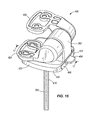
Fig. 15 is a perspective view of yet another hinge assembly embodying the invention. -
Fig. 16 is an exploded perspective view of the hinge assembly shown inFig. 15 . -
Fig. 17 is a cross-sectional view of the hinge assembly taken along section line 17-17 ofFig. 15 . -
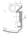
Fig. 18 is a perspective view of a mounting plate of the hinge assembly ofFig. 15 . -
Fig. 19 is a bottom perspective view of a hinge post of the hinge assembly ofFig. 15 . - Before any embodiments of the invention are explained in detail, it is to be understood that the invention is not limited in its application to the details of construction and the arrangement of components set forth in the following description or illustrated in the following drawings. The invention is capable of other embodiments and of being practiced or of being carried out in various ways.
-
Figs. 1 and2 illustrate a toiletseat hinge assembly 10 for mounting a toilet seat, or ring, and/or lid to a toilet bowl 14 (Figs. 4 ,6 , and7 ). Thehinge assembly 10 includes ahinge post 18 and afastener assembly 22 to secure thehinge post 18 to thetoilet bowl 14. Thefastener assembly 22 includes a threadedfastener 26, anadaptor 30, anexpandable bushing 34, and anut 38. Although only onehinge assembly 10 is shown, it should be readily apparent that a toilet typically includes twosimilar hinge assemblies 10 to mount the toilet seat and/or lid to thebowl 14. - The
hinge post 18 includes abase portion 42, apost portion 46, and a cover orcap 50. Thebase portion 42 is configured to sit on thetoilet bowl 14 and defines a recessedarea 54. The recessedarea 54 is bound by an upwardly-extendingsidewall 58 of thebase portion 42. The recessedarea 54 is shaped and sized to receive portions of the threadedfastener 26 and thebushing 34 when thehinge post 18 is positioned on thetoilet bowl 14. Anopening 62 is formed through thebase portion 42 in communication with the recessedarea 54. The illustratedopening 62 is an elongated opening that receives the threadedfastener 26 to align thefastener 26 with a bore 66 (Figs. 4 ,6 , and7 ) in thebowl 14. Theelongated opening 62 allows the position of thehinge post 18 to be adjusted relative to thefastener 26 and thebore 66. That is, theopening 62 allows thehinge post 18 to be moved laterally on thebowl 14 to accommodate and compensate for different sizes of toilet bowls and seats. For example, as shown inFig. 4 , thehinge post 18 is slid so that thefastener assembly 22 is at the right end of the opening 62 (i.e., the end adjacent the post portion 46) to move the toilet seat and/or lid rearward on thetoilet bowl 14. Similarly, as shown inFig. 7 , thehinge post 18 is slid so that thefastener assembly 22 is at the left end of the opening 62 (i.e., the end adjacent the cover 50) to move the toilet seat and/or lid forward on thetoilet bowl 14. Referring back toFig. 2 , a series of ridges orteeth 70 is formed on an upper surface of thebase portion 42 that surrounds theelongated opening 62. - The
post portion 46 includes twolegs 74 extending perpendicularly from thebase portion 42. Eachleg 74 defines abore 78 for receiving a pin. The pin pivotally mounts one or more hinge leaves to thehinge post 18 to pivotally couple the toilet seat and/or lid to thehinge assembly 10. - The
cover 50 is coupled to thebase portion 42 by a livinghinge 82. Thecover 50 is movable between an open position (Fig. 1 ) and a closed position. When in the open position, thecover 50 allows access to the recessedarea 54 of thebase portion 42. When in the closed position, thecover 50 substantially covers the recessedarea 54 to provide a clean appearance for thehinge assembly 10. Thecover 50 includes twobosses 86 that are configured to be received in correspondingapertures 90 in thebase portion 42 when thecover 50 is closed. Thebosses 86 and theapertures 90 create interference fits to releasably secure thecover 50 in the closed position. - The threaded
fastener 26 extends through theopening 62 in thehinge post 18 and thebore 66 in thetoilet bowl 14 to secure thehinge post 18 to thebowl 14. As shown inFig. 4 , thefastener 26 defines alongitudinal axis 94 extending through a first orupper end portion 98 and a second orlower end portion 102 of thefastener 26. The illustrated threadedfastener 26 is a steel or stainless steel bolt having ahead 106 and ashaft 110. The illustratedhead 106 is, for example, a conventional hex-shaped head formed on thefirst end portion 98 of thefastener 26 and is received in theadaptor 30. Theshaft 110 extends from thehead 106 through thebore 66 in thetoilet bowl 14. In some embodiments, theshaft 110 has a diameter between approximately 3/16 inch and approximately 3/8 inch. In the illustrated embodiment, theshaft 110 has a diameter of approximately 1/4 inch. - As shown in
Figs. 2 and4 , theadaptor 30 is coupled to theupper end portion 98 of thefastener 26. Theadaptor 30 may be composed of a plastic material such as, for example, 30% glass filled nylon. As shown inFig. 3 , theadaptor 30 includes a hex-shapedinner surface 114 that is configured to receive the hex-shapedhead 106 of thefastener 26. Referring back toFigs. 2 and4 , thehead 106 is pressed into theadaptor 30 to inhibit rotation of theadaptor 30 relative to thefastener 26. In some embodiments, theadaptor 30 may be molded directly to the threadedfastener 26. In such embodiments, thefastener 26 may include any suitable projection or projections that theadaptor 30 can be molded onto to inhibit relative rotation between theadaptor 30 and thefastener 26. - The illustrated
adaptor 30 includes a first orlower segment 118 coupled to theupper end portion 98 of the threadedfastener 26, a second orupper segment 122, and amiddle shear segment 126 connecting the first andsecond segments segments longitudinal axis 94. The first andsecond segments outer surfaces adaptor 30 and thefastener 26 about thelongitudinal axis 94. Theshear segment 126 is relatively thinner than the first andsecond segments shear segment 126 has a lower torque resistance than the first andsecond segments Fig. 6 , when a predetermined torque T is applied to thesecond segment 122, theshear segment 126 breaks, separating thesecond segment 122 from thefirst segment 118 and leaving thefirst segment 118 on thefastener 26. Such an arrangement inhibits over-tightening of thefastener 26 and removes excess material from theadaptor 30 so that thecover 50 of thehinge post 18 can be closed. - As shown in
Figs. 2 and4 , thebushing 34 extends into thebore 66 in thetoilet bowl 14, and thefastener 26 is inserted into thebushing 34 such that thebushing 34 is positioned around a portion of thefastener 26. Thebushing 34 may be composed of a plastic material such as, for example, 20% glass filled homopolymer polypropylene (HOPP). Thebushing 34 includes aflange 138 formed at the upper end of thebushing 34, anupper section 139 below theflange 138, and an expandablelower section 140. Thelower section 140 includes four axially extendingsegments 141 separated byslots 170 and has an outer diameter that is smaller than theopening 62 in thehinge post 18 and thebore 66 in thetoilet bowl 14. Theslots 170 are spaced approximately ninety degrees apart around thebushing 34. Theflange 138 is captured between theadaptor 30 and thebase portion 42 of thehinge post 18. As shown inFig. 5 , a series of ridges orteeth 142 is formed on an underside, or lower surface, of theflange 138. Theridges 142 on theflange 138 engage the correspondingridges 70 on thebase portion 42 to inhibit lateral movement of thebushing 34 relative to thehinge post 18 when thefastener 26 is tightened. - As shown in
Fig. 4 , thebushing 34 is capable of conforming to the various dimensions and shapes of mounting holes in toilet bowls. To this end, thebushing 34 includesprojections 146 extending radially outward from theupper section 139. In the illustrated embodiment, thebushing 34 includes four sets of twoprojections 146. In other embodiments, thebushing 34 may include fewer ormore projections 146. Theprojections 146 engage aninner surface 150 of the mounting hole or bore 66. Theprojections 146 deform and conform to the shape of thebore 66 and align thebushing 34 within thebore 66. The illustratedprojections 146 extend radially outward a greater distance than the diameter of thebore 66 such that theprojections 146 deflect upwardly when thebushing 34 is inserted into thebore 66. Cutouts 154 (Fig. 2 ) are formed in thebase portion 42 adjacent theelongated opening 62 to provide clearance for theprojections 146 when thebushing 34 is inserted through theopening 62. - The
nut 38 is threadably coupled to thelower end portion 102 of the threadedfastener 26. Thenut 38 is configured to expand theexpandable bushing 34 as thefastener 26 is rotated about theaxis 94 to secure thehinge post 18 to thetoilet bowl 14. The illustratednut 38 is generally cylindrical and includes a tapered or frustoconicalupper surface 158 that engages a correspondinginner surface 166 on thesegments 141 of thebushing 34. Thenut 38 has an outer diameter that is smaller than theopening 62 in thehinge post 18 and thebore 66 in thetoilet bowl 14 such that thenut 38 can be dropped through theopening 62 and thebore 66 with thefastener 26 and thebushing 34. Thenut 38 also has four ribs 162 (Fig. 2 ) extending from thesurface 158. Theribs 162 are spaced approximately ninety degrees apart around the nut, and theribs 162 fit within theslots 170 in thebushing 34. - As the
fastener 26 is rotated relative to thehinge post 18, theribs 162 inhibit thenut 38 from rotating relative to thebushing 34 with thefastener 26. Rather, as shown inFig. 6 , thenut 38 moves axially along theshaft 110 toward thehinge post 18. Thenut 38 has a larger outer diameter than the inner diameter of thebushing 34 such that thetapered surface 158 pushes thebushing segments 141 radially outward to expand thebushing 34. As thebushing 34 expands, thesegments 141 engage theinner surface 150 of thebore 66 to secure thebushing 34 and the threadedfastener 26 within thebore 66, thereby securing thehinge post 18 to thetoilet bowl 14. As thebushing 34 engages theinner surface 150 of thebore 66, thebushing 34 also increases the torque required for rotating thefastener 26 to the predetermined torque T that is necessary to break theshear segment 126 of theadaptor 30 and separate thesecond segment 122 from thefirst segment 118. - The illustrated
fastener assembly 22 facilitates rapid installation of the toiletseat hinge assembly 10 on a toilet bowl. The threadedfastener 26, theadaptor 30, thebushing 34, and thenut 38 can be preassembled as a single unit and then inserted through theelongated opening 62 of thehinge post 18 and into a bore of a toilet bowl to secure thehinge post 18 to the bowl. In addition, thenut 38 is keyed to thebushing 34 such that a user does not need to grasp and hold thenut 38 when rotating theadaptor 30 and thefastener 26. Instead, the user only needs to rotate theadaptor 30 until theshear segment 126 breaks to secure thehinge assembly 10 in place. This arrangement allows thefastener assembly 22 to be top-installed and top-tightened in restricted areas, such as on toilet bowls with blind bores. Furthermore, thefastener 26 is sized (e.g., between approximately 3/16 inch and 3/8 inch in diameter) to work with the normal variation of toilet bowl bore sizes. -
Fig. 8 illustrates the toiletseat hinge assembly 10 mounted to anothertoilet bowl 174. The illustratedtoilet bowl 174 has aflange 176 that is generally thinner than the flange of thetoilet bowl 14 shown inFigs. 4 ,6 , and7 . For example, theflange 176 may have a thickness, measured generally parallel to thelongitudinal axis 94, of approximately 0.5 inches. In addition, theflange 176 has larger radii that transition from atop surface 178 and abottom surface 182 of thebowl 174 to abore 186 through thebowl 174. In some embodiments, the radii may be between approximately 0.12 inches and approximately 0.25 inches. - In the illustrated embodiment, a substantial portion of the expandable
lower section 140 of thebushing 34 extends out of thebore 186 past thebottom surface 182 of thetoilet bowl flange 176. As thefastener 26 is rotated to tighten thenut 38, thelower section 140 not only grips aninner surface 190 of thebore 186, but also expands into the radius below thebore 186 to provide some degree of axial clamping. This axial clamping increases the security of thehinge assembly 10 on thebowl 174. Thenut 38 is also moved axially further toward thehinge post 18 such that thesecond end portion 102 of thefastener 26 extends out of and beyond thenut 38. -
Figs. 9 and10 illustrate another embodiment of a toiletseat hinge assembly 200. Thehinge assembly 200 includes ahinge post 204, abushing 208, a threadedfastener 212, and anut 216. Thehinge post 204 includes abase portion 220 and apost portion 224. Two hinge leaves 228, 232 are pivotally coupled to thepost portion 224 by apin 236. As shown inFigs. 10 and11 , thebase portion 220 defines anelongated opening 240, or slot, and includes anupper surface 244 that surrounds theopening 240. Theopening 240 allows for lateral adjustment of a toilet seat on a toilet bowl 248 (Fig. 11 ), as further described below. - The illustrated
bushing 208 includes arectangular flange 252 and alower section 256. Thelower section 256 extends through theopening 240 of thehinge post 204 and into a bore 260 (Fig. 11 ) in thetoilet bowl 248. Thebushing 208 also includes four sets of twoprojections 264 extending radially outward from thelower section 256. The sets ofprojections 264 are spaced approximately 90 degrees apart from each other. As shown inFig. 11 , theprojections 264 engage aninner surface 268 of thetoilet bowl 248 that defines thebore 260. Theprojections 264 deflect as thebushing 208 is inserted into thebore 260 to help position and secure thebushing 208 within thebore 260. - The
flange 252 is supported on theupper surface 244 of thehinge post 204 over theopening 240. As shown inFig. 12 , theflange 252 includes alower surface 272 and a series ofteeth 276 formed on thelower surface 272. Theteeth 276 engage a similar series ofteeth 280 formed on theupper surface 244 of thehinge post 204. Theteeth flange 252 is clamped down onto thehinge post 204 by the threadedfastener 212 and thenut 216, inhibiting movement of thehinge post 204 relative to thebushing 208 and thefastener 212. When the threadedfastener 212 is loosened, theteeth hinge post 204. In particular, theelongated opening 240 allows thehinge post 204 to slide horizontally along the toilet bowl 248 (Fig. 11 ) to adjust a position of thehinge post 204, and thereby the toilet seat and/or lid, in a front-to-back direction. - As shown in
Figs. 10 and11 , the illustrated threadedfastener 212 is a shear bolt that functions in the same manner as the threadedfastener 26 and theadaptor 30 ofFigs. 1-8 . Thefastener 212 includes a threadedportion 284, or shaft, and ahead portion 288 having afirst segment 292, asecond segment 296, and ashear segment 300. In the illustrated embodiment, theentire fastener 212, including the threadedshaft 284, thefirst segment 292, thesecond segment 296, and theshear segment 300, is composed of a plastic material (e.g., by injection molding) and is unitary. The first andsecond segments outer surfaces fastener 212. Theshear segment 300 connects the first andsecond segments second segment 296. Thenut 216 can be held by hand or with a tool when tightening thefastener 212. Thefirst segment 292 has the same geometry as thesecond segment 296 to facilitate rotating and removing thefastener 212 after thesecond segment 296 is broken off. - In other embodiments, the
flange 252 of thebushing 208 could be integrally formed (e.g., by injection molding) with thefastener 212 such that theflange 252 would essentially also be part of thehead portion 288 of thefastener 212. In such embodiments, either an ordinary nut or a shear nut (similar to the shear nuts disclosed inU.S. Publication No. 2009/0276944 ('the 944 Publication), the entire contents of which are incorporated by reference herein) could be used to secure thefastener 212 to thetoilet bowl 248. Theteeth 276 on theflange 252 and theteeth 280 on thehinge post 204 could still help fix thehinge post 204 relative to thetoilet bowl 248 when thefastener 212 is tightened and allow for adjustment of thehinge post 204 on thetoilet bowl 248 when thefastener 212 is loosened. -
Figs. 13 and 14 illustrate another threadedfastener 312 for use with thehinge assembly 200. Similar to the threadedfastener 212 described above, the illustratedfastener 312 includes a threadedportion 316, or shaft, and ahead portion 320 having afirst segment 324, asecond segment 328, and ashear segment 332. Theshaft 316, thefirst segment 324, thesecond segment 328, and theshear segment 332 are composed of a plastic material and are unitary. In the illustrated embodiment, anannular recess 336 is formed in anouter surface 340 of thefirst segment 324. Theannular recess 336 is configured to be engaged by a quick-release hinge post, similar to the recess 855 illustrated and described in Figs. 24 and 25 of the '944 Publication. A similar recess can also be formed in thefirst section 118 of theadaptor 30 shown inFigs. 1-8 . - The illustrated threaded
fastener 312 also includes twoslots surface 352 of thefirst segment 324. Theslots outer surface 340 of thefirst segment 324. The illustratedslots fastener 312. In other embodiments, thefastener 312 may include a single slot for engagement by a flat head screwdriver. -
Figs. 15-17 illustrate another embodiment of a toiletseat hinge assembly 400 for coupling a toilet seat and/or lid to atoilet bowl 404. The illustratedhinge assembly 400 includes a mountingplate 408, aclip 412, a threadedfastener 416, ahinge post 420, and two hinge leaves 424, 428. - As shown in
Figs. 16 and18 , the mountingplate 408, or first member, includes abottom wall 432, afront wall 436, arear wall 440, and twoside walls front wall 436, therear wall 440, and theside walls bottom wall 432 to define aplate cavity 452. Aplate opening 456 is formed through thebottom wall 432 in communication with theplate cavity 452. Thebottom wall 432 includes afront ledge 460 between theplate opening 456 and thefront wall 436, and arear ledge 464 between theplate opening 456 and therear wall 440. Thefirst side wall 444 is positioned outside of theplate opening 456 and includes an outwardly extending first wing orshoulder 468 that extends the length of theside wall 444. Thefirst shoulder 468 defines an undercut 472 in thefirst side wall 444. Thesecond side wall 448 is positioned outside of the plate opening 456 opposite thefirst side wall 444 and includes an outwardly extending second wing orshoulder 476 that extends the length of theside wall 448. Thesecond shoulder 476 defines an undercut 480 in thesecond side wall 448. - The mounting
plate 408 also includes atab 484 extending from thefront wall 436 away from theplate cavity 452. Thetab 484 is deflectable between a locked position and an unlocked position and is biased to the locked position. As shown inFig. 17 , when in the locked position, thetab 484 extends substantially parallel to thebottom wall 432 and substantially perpendicular to thefront wall 436. When in the unlocked position, thetab 484 is angled obliquely relative to thebottom wall 432 and thefront wall 436. Thetab 484 includes an upwardly extendingprojection 488. Theprojection 488 includes anangled surface 492 on the side of theprojection 488 closer to thefront wall 436. - As shown in
Figs. 16 and18 , the mountingplate 408 further includes aforward wall 496. Theforward wall 496 is positioned forward of thefront wall 436 and is connected to thefront wall 436 byextensions side walls recess 508 is formed in the upper surface of theforward wall 496. Therecess 508 provides clearance for thetab 484 such that thetab 484 can extend through theforward wall 496 and be depressed to the unlocked position. In other embodiments, theforward wall 496 and thefront wall 436 may be a single continuous wall that defines therecess 508. In still other embodiments, theforward wall 496 and theside wall extensions - As shown in
Fig. 16 , theclip 412, or second member, includes ahorizontal plate 512 and twoclip side walls side walls front end 524 to arear end 528 of theplate 512 on opposite sides of theplate 512. Anelongated clip opening 532 is defined in theplate 512 between the front andrear ends Fig. 17 , theclip 412 is positioned in theplate cavity 452 of the mountingplate 408 so that theclip 412 engages and is supported by thefront ledge 460 and therear ledge 464. In addition, thefront end 524 of theclip 412 abuts thefront wall 436 of theplate 408, therear end 528 of theclip 412 abuts therear wall 440 of theplate 408, and theclip opening 532 overlaps theplate opening 456. Theclip 412 is thereby movable relative to theplate 408 in a horizontal side-to-side direction X within theplate cavity 452. - In the illustrated embodiment, the
fastener 416 is a conventional bolt including ahead 536 and a threadedshaft 540. Thehead 536 engages and is supported by an upper surface of thehorizontal plate 512 of theclip 412. The illustratedhead 536 is a Phillips head, but may alternatively be a flat head, a hex head, or any other type of head suitable for engagement and rotation by a tool. Theshaft 540 extends through theclip opening 532 and the plate opening 456 into a bore 544 (Fig. 17 ) in thetoilet bowl 404. Theshaft 540 is movable within theclip opening 532 in a horizontal front-to-back direction Y from afirst end 548 of theopening 532 to asecond end 552 of theopening 532. Thefastener 416 can be tightened to thetoilet bowl 404 with a nut to fix the location of theshaft 540 within theclip opening 532. Tightening thefastener 416 also clamps theclip 412 and the mountingplate 408 between thehead 536 and thetoilet bowl 404, preventing front-to-back and side-to-side movement of the mountingplate 408 on thetoilet bowl 404. In some embodiments, thefastener 416 may include a shear head (similar to the threaded fasteners ofFigs. 1-14 ) or the nut may be a shear nut (similar to the nuts disclosed in the '944 Publication). - As shown in
Fig. 19 , thehinge post 420 includes abase portion 556 and apost portion 560. Thepost portion 560 extends upwardly from thebase portion 556 and defines anopening 564 for pivotally coupling the hinge leaves 424, 428 to thehinge post 420. Thebase portion 556 defines abase cavity 568 having afront opening 572 and abottom opening 576. Thebase portion 556 also includes two inwardly extendingside ledges cavity 568. As shown inFig 17 , alip 588 is formed generally above thecavity 568 and is configured to engage theprojection 488 on thetab 484 of the mountingplate 408. In other embodiments, thetab 484 may extend from thehinge post 420 and thelip 588 may be formed on the mountingplate 408. - Referring back to
Figs. 15 and16 , the hinge leaves 424, 428 are pivotally coupled to thehinge post 420 by a pin (not shown). Thefirst leaf 424 is configured to be coupled to a toilet seat or ring. Thesecond leaf 428 is configured to be coupled to a toilet lid or cover. In other embodiments, the seat and the lid may be pivotally connected to thehinge post 420 in any manner, including without hinge leaves. In some embodiments, the toiletseat hinge assembly 400 may be a slow-close hinge. - As shown in
Fig. 16 , theplate opening 456 and theclip opening 532 have dimensions that are larger than an outer diameter of thefastener 416 such that the mountingplate 408 and theclip 412 are movable relative to thefastener 416. In particular, theplate opening 456 has a length LP and a width WP (Fig. 18 ) that are larger than the outer diameter of thefastener 416 so that theclip 412 is movable from side-to-side in the horizontal direction X within theplate cavity 452. Theclip 412 contacts thefirst side wall 444 of theplate 408 at one extreme and contacts thesecond side wall 448 of theplate 408 at the other extreme. In addition, theclip opening 532 has a length LC that is larger than the outer diameter of thefastener 416 so that thefastener 416 is movable from front-to-back in the horizontal direction Y within theclip opening 532. Thefastener 416 contacts thefirst end 548 of theopening 532 at one extreme and contacts thesecond end 552 of theopening 532 at the other extreme. Movement in these two horizontal directions X, Y allows the position of the mountingplate 408 to be adjusted relative to thebore 544 in thetoilet bowl 404. This positional adjustability allows thehinge assembly 400 to compensate for differences in spacing of bores in different toilet bowls, as compared to the spacing of the hinge attachment points on the toilet seat and the lid, and to adjust the location of the seat and the lid over different toilet bowls. After the mountingplate 408 is positioned as desired on thetoilet bowl 404, thefastener 416 is tightened to secure the mountingplate 408 and theclip 412 to thetoilet bowl 404. - The
hinge post 420 is then secured to the mountingplate 408 by sliding thepost 420 along thetoilet bowl 404 and onto theplate 408 in a forward horizontal direction F (Fig. 17 ). Therear wall 440 of the mountingplate 408 enters thehinge post 420 through thefront opening 572 so that thebase cavity 568 receives the mountingplate 408 and theclip 412. As thehinge post 420 is slid onto the mountingplate 408, thefirst ledge 580 of thehinge post 420 slides into the first undercut 472 of theplate 408, capturing theledge 580 between thefirst shoulder 468 and thetoilet bowl 404. In addition, thesecond ledge 584 of thehinge post 420 slides into the second undercut 480 of theplate 408, capturing theledge 584 between thesecond shoulder 476 and thetoilet bowl 404. Theshoulders ledges hinge post 420 from lifting away from thetoilet bowl 404 after thehinge post 420 is installed. - As the
hinge post 420 is slid on the mountingplate 408, thetab 484 is automatically depressed to the unlocked position by thehinge post 420. In particular, theangled surface 492 of theprojection 488 engages and rides under an edge of thehinge post 420 to deflect thetab 484 toward thetoilet bowl 404. This allows theprojection 488 to pass through thefront opening 572 of thehinge post 420 and into thebase cavity 568. Once the mountingplate 408 is sufficiently within thecavity 568, thetab 484 automatically snaps into the locked position (Fig. 17 ) so that theprojection 488 engages thelip 588 to inhibit movement of thehinge post 420 in a rearward horizontal direction R off of the mountingplate 408. As shown inFig. 17 , when the mountingplate 408 is fully inserted into thebase cavity 568, theprojection 488 engages thelip 588, therear wall 440 of theplate 408 abuts aninner wall 592 of thehinge post 420, and theforward wall 496 of theplate 408 is flush with an outer surface of thehinge post 420. In this position, thetab 484 extends outwardly from thehinge post 420 in the forward horizontal direction F. - To remove the
hinge post 420 from the mountingplate 408, a user manually depresses thetab 484 toward thetoilet bowl 404 to the unlocked position. In this position, theprojection 488 on thetab 484 disengages thelip 588 such that thehinge post 420 can be slid off of the mountingplate 408 in the rearward horizontal direction R. - The directions used to describe the hinge assemblies (e.g., front, back, side, forward, rearward, upper, lower, etc.) correspond to the directions of a hinge assembly when secured to a toilet bowl in one orientation. The directional language should not be regarded as limiting as the hinge assemblies could be oriented in other directions and ways on a toilet bowl and still function as described above. For example, the term "front" as used above could refer to a position to the left, right, or rear of a toilet bowl.
- Various features and advantages of the invention are set forth in the following claims.
- Other aspects of the invention include the following:
- Aspect 1. A hinge assembly for mounting a toilet seat to a toilet bowl, the hinge assembly comprising:
- a hinge post;
- a bolt having a head and a threaded shaft configured to extend into a bore in the toilet bowl for securing the hinge post to the toilet bowl;
- an adaptor having a first segment coupled to the head of the bolt, a second segment, and a shear segment connecting the first and second segments, the first and second segments both configured to be engaged by a tool to rotate the bolt, the shear segment having a lower torque resistance than the first and second segments such that the shear segment breaks when a torque applied to the second segment reaches a predetermined amount; and
- a nut threadably coupled to the threaded shaft of the bolt;
- wherein the head of the bolt is fit into the adaptor such that the first segment of the adaptor surrounds the head.
- Aspect 2. The hinge assembly of Aspect 1, wherein the bolt is composed of metal and the adaptor is composed of a plastic material.
- Aspect 3. The hinge assembly of Aspect 1, wherein the threaded shaft of the bolt has a diameter between approximately 3/16 inch and approximately 3/8 inch.
- Aspect 4. The hinge assembly of Aspect 1, further comprising an expandable bushing positioned around a portion of the bolt between the adaptor and the nut, wherein at least a portion of the expandable bushing is configured to extend into the bore in the toilet bowl, and wherein the expandable bushing expands as the bolt is rotated relative to the hinge post to secure the hinge post to the toilet bowl.
-
Aspect 5. The hinge assembly of Aspect 4, wherein the expandable bushing includes at least two axially extending segments separated by at least two slots, and wherein the at least two axially extending segments deflect radially outward to expand the expandable bushing as the bolt is rotated relative to the hinge post. - Aspect 6. The hinge assembly of
Aspect 5, wherein the nut expands the expandable bushing as the bolt is rotated relative to the hinge post. - Aspect 7. The hinge assembly of Aspect 6, wherein the nut includes a rib, and wherein the rib fits within one of the at least two slots of the expandable bushing to inhibit the nut from rotating relative to the expandable bushing.
- Aspect 8. The hinge assembly of Aspect 6, wherein the nut has an outer diameter configured to be smaller than an inner diameter of the bore of the toilet bowl.
- Aspect 9. The hinge assembly of Aspect 4, wherein the expandable bushing includes a projection extending radially outward therefrom, and wherein the projection is configured to engage an inner surface of the bore of the toilet bowl to align the bushing within the bore.
-
Aspect 10. The hinge assembly of Aspect 9, wherein the projection is configured to deflect as the expandable bushing is inserted into the bore. -
Aspect 11. A hinge assembly for mounting a toilet seat to a toilet bowl, the hinge assembly comprising:- a hinge post;
- a fastener for securing the hinge post to the toilet bowl, the fastener including
- a threaded portion configured to extend into a bore of the toilet bowl,
- a first segment coupled to an end portion of the threaded portion,
- a second segment configured to be engaged by a tool to rotate the fastener, and
- a shear segment connecting the first and second segments, the shear segment having a lower torque resistance than the first and second segments such that the shear segment breaks when a torque applied to the second segment reaches a predetermined amount; and
- a nut threadably coupled to the threaded portion of the fastener;
- wherein the threaded portion, the first segment, the second segment, and the shear segment of the fastener are composed of a plastic material and are unitary.
-
Aspect 12. The hinge assembly ofAspect 11, wherein the first segment is also configured to be engaged by a tool to rotate the fastener. - Aspect 13. The hinge assembly of
Aspect 11, wherein the first segment defines an annular recess configured to be engaged by a quick-release hinge post. -
Aspect 14. The hinge assembly ofAspect 11, wherein the threaded portion has a slot, and wherein the slot is configured to be engaged by a screwdriver to rotate the fastener. - Aspect 15. The hinge assembly of
Aspect 14, wherein the slot is formed on an upward-facing surface of the first segment. - Aspect 16. The hinge assembly of
Aspect 14, wherein the slot is formed within a periphery defined by the first segment. -
Aspect 17. A hinge assembly for mounting a toilet seat to a toilet bowl, the hinge assembly comprising:- a hinge post defining an opening and including an upper surface that surrounds the opening;
- a threaded fastener extending through the opening of the hinge post and configured to extend into a bore in the toilet bowl;
- a bushing positioned around a portion of the threaded fastener, the bushing including a flange and an expandable lower section configured to extend into the bore in the toilet bowl, the flange supported by the upper surface of the hinge post over the opening; and
- a nut threadably coupled to the threaded fastener;
- wherein the nut expands the expandable lower section of the bushing as the threaded fastener is rotated relative to the hinge post to secure the hinge post to the toilet bowl.
-
Aspect 18. The hinge assembly ofAspect 17, wherein the nut has an outer diameter configured to be smaller than an inner diameter of the bore of the toilet bowl. - Aspect 19. The hinge assembly of
Aspect 17, wherein the nut is generally cylindrical and includes a frustoconical upper surface, and wherein the frustconical upper surface enters the expandable lower section of the bushing as the threaded fastener is rotated. - Aspect 20. The hinge assembly of Aspect 19, wherein the expandable lower section defines at least two slots to facilitate expansion of the bushing.
- Aspect 21. The hinge assembly of Aspect 20, wherein the nut includes a rib, and wherein the rib fits within one of the at least two slots of the bushing to inhibit the nut from rotating relative to the bushing.
-
Aspect 22. The hinge assembly of Aspect 21, wherein the rib extends from the frustoconical upper surface of the nut. - Aspect 23. The hinge assembly of
Aspect 17, wherein the bushing includes a projection extending radially outward therefrom, and wherein the projection is configured to engage an inner surface of the bore of the toilet bowl to align the bushing within the bore. - Aspect 24. The hinge assembly of Aspect 23, wherein the projection is configured to deflect as the bushing is inserted into the bore.
- Aspect 25. The hinge assembly of
Aspect 17, wherein the hinge post is movable relative to the threaded fastener and the bushing to adjust a position of the hinge post on the toilet bowl. -
Aspect 26. The hinge assembly of Aspect 25, wherein the hinge post is movable horizontally along the toilet bowl relative to the threaded fastener and the bushing. - Aspect 27. The hinge assembly of
Aspect 26, wherein the hinge post includes a first series of teeth formed on the upper surface, wherein the flange of the bushing includes a lower surface and a second series of teeth formed on the lower surface, and wherein the first series of teeth engages the second series of teeth to inhibit movement of the hinge post relative to the bushing when the threaded fastener is tightened. - Aspect 28. A hinge assembly for mounting a toilet seat to a toilet bowl, the hinge assembly comprising:
- a hinge post defining an opening and including an upper surface that surrounds the opening;
- a threaded fastener extending through the opening of the hinge post and configured to extend into a bore in the toilet bowl;
- a bushing positioned around a portion of the threaded fastener, the bushing including a flange and a lower section configured to extend into the bore in the toilet bowl, the flange supported by the upper surface of the hinge post over the opening, the lower section having an outer diameter that is smaller than the opening in the hinge post such that the hinge post is movable relative to the threaded fastener and the bushing to adjust a position of the hinge post on the toilet bowl; and
- a nut threadably coupled to the threaded fastener.
- Aspect 29. The hinge assembly of Aspect 28, wherein the hinge post is movable horizontally along the toilet bowl relative to the threaded fastener and the bushing.
-
Aspect 30. The hinge assembly of Aspect 29, wherein the hinge post includes a first series of teeth formed on the upper surface, wherein the flange of the bushing includes a lower surface and a second series of teeth formed on the lower surface, and wherein the first series of teeth engages the second series of teeth to inhibit movement of the hinge post relative to the bushing when the threaded fastener is tightened. - Aspect 31. The hinge assembly of Aspect 28, wherein the bushing includes a projection extending radially outward therefrom, and wherein the projection is configured to engage an inner surface of the bore of the toilet bowl to align the bushing within the bore.
- Aspect 32. The hinge assembly of Aspect 31, wherein the projection is configured to deflect as the bushing is inserted into the bore.
- Aspect 33. A method of installing a hinge post on a toilet bowl, the hinge post defining an opening and including an upper surface that surrounds the opening, the method comprising;
assembling a bushing on a threaded fastener, the bushing including a flange;
inserting the assembled threaded fastener and bushing through the opening of the hinge post and into a bore of the toilet bowl such that the flange of the bushing is supported by the upper surface of the hinge post;
adjusting a position of the hinge post on the toilet bowl; and
rotating the threaded fastener to secure the hinge post to the toilet bowl. -
Aspect 34. The method of Aspect 33, wherein adjusting the position of the hinge post on the toilet bowl includes moving the hinge post horizontally relative to the toilet bowl after the assembled threaded fastener and bushing is inserted into the bore of the toilet bowl. - Aspect 35. The method of Aspect 33, wherein the hinge post includes a first series of teeth formed on the upper surface, wherein the flange of the bushing includes a lower surface and a second series of teeth formed on the lower surface, and further comprising engaging the first series of teeth with the second series of teeth to inhibit movement of the hinge post when the threaded fastener is tightened.
- Aspect 36. The method of Aspect 33, further comprising assembling a nut on the threaded fastener, and wherein inserting the assembled threaded fastener and bushing through the opening of the hinge post includes inserting the assembled threaded fastener, bushing, and nut through the opening of the hinge post and into the bore of the toilet bowl.
- Aspect 37. The method of Aspect 36, wherein the bushing includes an expandable lower section that is inserted into the bore of the toilet bowl, and further comprising expanding the expandable lower section of the bushing with the nut as the threaded fastener is rotated to secure the hinge post to the toilet bowl.
-
Aspect 38. The method of Aspect 33, wherein the bushing includes a projection extending radially outward therefrom, and further comprising deflecting the projection as the assembled threaded fastener and bushing is inserted into the bore of the toilet bowl to align the bushing within the bore. - Aspect 39. The method of Aspect 33, further comprising:
- assembling an adaptor on the threaded fastener, the adaptor having a first segment coupled to an end portion of the threaded fastener opposite the nut, a second segment, and a shear segment connecting the first and second segments, the first and second segments both configured to be engaged by a tool to rotate the threaded fastener, the shear segment having a lower torque resistance than the first and second segments;
- rotating the second segment of the adaptor to rotate the threaded fastener; and
- breaking the shear segment of adaptor when a torque applied to the second segment reaches a predetermined amount.
- Aspect 40. A hinge assembly for mounting a toilet seat to a toilet bowl, the hinge assembly comprising:
- a hinge post defining an opening and including an upper surface that surrounds the opening;
- a threaded fastener extending through the opening of the hinge post and configured to extend into a bore in the toilet bowl, the threaded fastener having a first end portion and a second end portion;
- an adaptor having a first segment coupled to the first end portion of the threaded fastener, a second segment, and a shear segment connecting the first and second segments, the first and second segments both configured to be engaged by a tool to rotate the fastener, the shear segment having a lower torque resistance than the first and second segments such that the shear segment breaks when a torque applied to the second segment reaches a predetermined amount;
- a nut threadably coupled to the second end portion of the threaded fastener; and
- a bushing positioned around a portion of the threaded fastener between the adaptor and the nut, the bushing including a flange and an expandable lower section configured to extend into the bore in the toilet bowl, the flange supported by the upper surface of the hinge post over the opening, the expandable lower section having an outer diameter that is smaller than the opening in the hinge post such that the hinge post is movable relative to the threaded fastener and the bushing to adjust a position of the hinge post on the toilet bowl;
- wherein the nut expands the expandable lower section of the bushing as the threaded fastener is rotated relative to the hinge post to secure the hinge post to the toilet bowl.
- Aspect 41. The hinge assembly of Aspect 40, wherein the threaded fastener includes a bolt having a head at the first end portion, and wherein the head is fit into the adaptor such that the first segment of the adaptor surrounds the head.
-
Aspect 42. The hinge assembly of Aspect 40, wherein the threaded fastener and the adaptor are integrally formed as a single piece. - Aspect 43. A hinge assembly for mounting a toilet seat to a toilet bowl, the hinge assembly comprising:
- a first member configured to be supported on the toilet bowl for movement along the toilet bowl, the first member defining a first opening;
- a second member supported on the first member for movement along the first member, the second member defining a second opening;
- a threaded fastener extending through the first opening in the first member and the second opening in the second member, the threaded fastener configured to extend into a bore in the toilet bowl to secure the first and second members to the toilet bowl; and
- a hinge post coupled to at least one of the first member and the second member;
- wherein dimensions of the first opening and the second opening are larger than an outer diameter of the threaded fastener such that the first and second members are movable relative to the threaded fastener to adjust a position of the hinge post relative to the toilet bowl in both a front-to-back direction and a side-to-side direction.
- Aspect 44. The hinge assembly of Aspect 43, wherein the first opening has a length and a width that are both larger than the outer diameter of the threaded fastener, and wherein the second opening has a length that is larger than the outer diameter of the threaded fastener.
- Aspect 45. The hinge assembly of Aspect 43, wherein the threaded fastener includes a head that engages and is supported by the second member.
-
Aspect 46. The hinge assembly of Aspect 43, wherein the first member includes a wall configured to extend away from the toilet bowl, wherein the wall defines a cavity, and wherein the second member is positioned within the cavity. - Aspect 47. The hinge assembly of Aspect 43, wherein the hinge post defines a cavity that receives the first and second members to secure the hinge post to the first and second members.
- Aspect 48. The hinge assembly of Aspect 47, further comprising a tab coupled to one of the first member, the second member, and the hinge post to releasably secure the hinge post to the first and second members, wherein the tab is manually operable to allow removal of the hinge post from the first and second members.
- Aspect 49. A hinge assembly for mounting a toilet seat to a toilet bowl, the hinge assembly comprising:
- a member configured to be supported on the toilet bowl;
- a threaded fastener extending through the member and configured to extend into a bore in the toilet bowl to secure the member to the toilet bowl;
- a hinge post defining a cavity, the hinge post being slidable along the toilet bowl onto the member such that the cavity receives the member; and
- a tab coupled to one of the member and the hinge post to releasably secure the hinge post to the member, the tab being manually operable to allow removal of the hinge post from the member.
-
Aspect 50. The hinge assembly of Aspect 49, wherein the tab includes a projection and the other of the member and the hinge post includes a lip, wherein the projection engages the lip to secure the hinge post to the member, and wherein the projection disengages the lip when the tab is manually operated. - Aspect 51. The hinge assembly of Aspect 49, wherein the hinge post is slid onto the member in a direction, and wherein the tab extends from the one of the member and the hinge post in the same direction.
- Aspect 52. The hinge assembly of Aspect 51, wherein the tab is configured to be depressed toward the toilet bowl to allow removal of the hinge post from the member.
- Aspect 53. The hinge assembly of Aspect 49, wherein the member includes a shoulder that is spaced apart from the toilet bowl when the member is supported on the toilet bowl, and wherein the hinge post includes a ledge that fits between the shoulder and the toilet bowl when the hinge post is slid onto the member.
Claims (6)
- A hinge assembly for mounting a toilet seat to a toilet bowl, the hinge assembly comprising:a hinge post;a fastener for securing the hinge post to the toilet bowl, the fastener including
a threaded portion configured to extend into a bore of the toilet bowl,
a first segment coupled to an end portion of the threaded portion,
a second segment configured to be engaged by a tool to rotate the fastener, and
a shear segment connecting the first and second segments, the shear segment having a lower torque resistance than the first and second segments such that the shear segment breaks when a torque applied to the second segment reaches a predetermined amount; anda nut threadably coupled to the threaded portion of the fastener;wherein the threaded portion, the first segment, the second segment, and the shear segment of the fastener are composed of a plastic material and are unitary. - The hinge assembly of claim 1, wherein the first segment is also configured to be engaged by a tool to rotate the fastener.
- The hinge assembly of claim 1, wherein the first segment defines an annular recess configured to be engaged by a quick-release hinge post.
- The hinge assembly of claim 1, wherein the threaded portion has a slot, and wherein the slot is configured to be engaged by a screwdriver to rotate the fastener.
- The hinge assembly of claim 4, wherein the slot is formed on an upward-facing surface of the first segment.
- The hinge assembly of claim 4, wherein the slot is formed within a periphery defined by the first segment.
Applications Claiming Priority (4)
| Application Number | Priority Date | Filing Date | Title |
|---|---|---|---|
| US201061424111P | 2010-12-17 | 2010-12-17 | |
| US201161451708P | 2011-03-11 | 2011-03-11 | |
| US201161550155P | 2011-10-21 | 2011-10-21 | |
| EP11848873.3A EP2640246B1 (en) | 2010-12-17 | 2011-12-16 | Toilet seat hinge assembly |
Related Parent Applications (2)
| Application Number | Title | Priority Date | Filing Date |
|---|---|---|---|
| EP11848873.3A Division EP2640246B1 (en) | 2010-12-17 | 2011-12-16 | Toilet seat hinge assembly |
| EP11848873.3A Division-Into EP2640246B1 (en) | 2010-12-17 | 2011-12-16 | Toilet seat hinge assembly |
Publications (2)
| Publication Number | Publication Date |
|---|---|
| EP2974638A1 true EP2974638A1 (en) | 2016-01-20 |
| EP2974638B1 EP2974638B1 (en) | 2018-04-11 |
Family
ID=46245116
Family Applications (2)
| Application Number | Title | Priority Date | Filing Date |
|---|---|---|---|
| EP11848873.3A Not-in-force EP2640246B1 (en) | 2010-12-17 | 2011-12-16 | Toilet seat hinge assembly |
| EP15175348.0A Not-in-force EP2974638B1 (en) | 2010-12-17 | 2011-12-16 | Toilet seat hinge assembly |
Family Applications Before (1)
| Application Number | Title | Priority Date | Filing Date |
|---|---|---|---|
| EP11848873.3A Not-in-force EP2640246B1 (en) | 2010-12-17 | 2011-12-16 | Toilet seat hinge assembly |
Country Status (6)
| Country | Link |
|---|---|
| US (2) | US9107547B2 (en) |
| EP (2) | EP2640246B1 (en) |
| CN (1) | CN103379846B (en) |
| BR (1) | BR112013015248B1 (en) |
| MX (1) | MX336773B (en) |
| WO (1) | WO2012083096A1 (en) |
Families Citing this family (10)
| Publication number | Priority date | Publication date | Assignee | Title |
|---|---|---|---|---|
| CH705265A2 (en) * | 2011-07-05 | 2013-01-15 | Maria Ayer | Toilet lid garnish. |
| JP6920027B2 (en) | 2015-03-17 | 2021-08-18 | ロレックス・ソシエテ・アノニムRolex Sa | Rivets for watches |
| US9833114B2 (en) * | 2015-05-19 | 2017-12-05 | Etablissements Dubourgel Grange | Device for fastening a toilet seat which can be rapidly fitted/removed |
| US20180146830A9 (en) * | 2016-03-29 | 2018-05-31 | Handy Tissue, Llc | Toilet paper dispenser |
| US10285546B2 (en) * | 2017-02-13 | 2019-05-14 | Topseat International, Inc. | System and method for removably mounting toilet seat to toilet bowl |
| US10610068B2 (en) * | 2018-01-06 | 2020-04-07 | Kohler Co. | Toilet seat and hinge |
| USD962746S1 (en) * | 2019-05-14 | 2022-09-06 | Bemis Manufacturing Company | Display mount for a toilet seat assembly |
| US11445837B2 (en) | 2019-05-14 | 2022-09-20 | Bemis Manufacturing Company | Display mount for toilet seat assembly |
| MX2021001913A (en) * | 2020-02-18 | 2021-08-19 | Bemis Mfg Co | Fastening assembly for toilet seat hinge. |
| DE102020122834A1 (en) | 2020-09-01 | 2022-03-03 | Eureha Gmbh | Fastening device, toilet seat component and assembly unit |
Citations (4)
| Publication number | Priority date | Publication date | Assignee | Title |
|---|---|---|---|---|
| GB2140523A (en) * | 1983-05-17 | 1984-11-28 | Hepworth Electrical Developmen | Shear head screws or bolts, or shear head adapter |
| US20050217008A1 (en) * | 2004-04-01 | 2005-10-06 | Vierkant Erich C Iii | Releasable toilet seat assembly |
| US20090211005A1 (en) * | 2008-02-22 | 2009-08-27 | Joseph Hand | Hinge assembly for a toilet seat |
| US20090276944A1 (en) | 2008-02-22 | 2009-11-12 | Bemis Manufacturing Company | Hinge assembly for a toilet seat |
Family Cites Families (75)
| Publication number | Priority date | Publication date | Assignee | Title |
|---|---|---|---|---|
| US462601A (en) | 1891-11-03 | Expansion-fastener | ||
| US784845A (en) | 1904-11-11 | 1905-03-14 | Frederic H Evans | Expansion-bolt. |
| US2971425A (en) | 1956-12-31 | 1961-02-14 | Richard H Blakeley | Blind fastener having an expandable nut drawn into endwise abutment with work surface |
| US3331267A (en) * | 1965-08-30 | 1967-07-18 | Fred R Tietge | Wrench having a reduced portion which fails at the desired torque |
| US3390906A (en) | 1967-07-31 | 1968-07-02 | Hi Shear Corp | Joint with inherently limited torque level |
| US3444775A (en) | 1968-02-16 | 1969-05-20 | Lockheed Aircraft Corp | Nut formed with multiple torque-off collars |
| US3561317A (en) | 1969-04-04 | 1971-02-09 | Anaconda American Brass Co | Self-indicating clamping bolt |
| US3568221A (en) | 1969-04-09 | 1971-03-09 | American Standard Inc | Hinge assembly |
| US3699614A (en) | 1970-04-20 | 1972-10-24 | American Standard Inc | Toilet seat cover mounting |
| US3742583A (en) | 1972-01-14 | 1973-07-03 | Standard Pressed Steel Co | Method of using twist-off nut to assemble a joint |
| US4029379A (en) | 1973-09-14 | 1977-06-14 | Westinghouse Electric Corporation | Electrical bus duct with torque indication nut |
| DE2458317B2 (en) | 1974-12-10 | 1979-04-05 | Heinrich 6102 Pfungstadt Liebig | Expansion anchor |
| US4015505A (en) | 1976-02-23 | 1977-04-05 | Illinois Tool Works Inc. | One sided fastener device |
| US4080671A (en) | 1976-08-27 | 1978-03-28 | Geberit Ag | Arrangement for swingable mounting of a toilet seat |
| US4290337A (en) | 1977-01-03 | 1981-09-22 | Nittetsu Bolten Kabushiki Kaisha | Fastener set |
| US4087884A (en) | 1977-02-03 | 1978-05-09 | Abe Seiderman | Lateral extension bowl attachment device for adapting standard relatively hinged toilet seat and cover assemblies for use with non-standard bowls |
| EP0002654B1 (en) | 1977-12-24 | 1982-01-20 | Heinrich Liebig | Fastening device with a dowel positively locking in a undercut bore |
| US4159548A (en) | 1978-02-15 | 1979-07-03 | Moldex Limited | Lift-off hinge assembly for toilets and the like |
| US4148104A (en) | 1978-02-17 | 1979-04-10 | Milton Ginsburg | Toilet seat hinge |
| US4326307A (en) | 1978-06-02 | 1982-04-27 | Baillie Kenneth D | Releasable toilet seat clamp |
| US4215600A (en) * | 1978-10-12 | 1980-08-05 | Kesselman David A | Torque limiter for use with off-the-shelf fastening elements |
| US4319365A (en) * | 1980-02-11 | 1982-03-16 | Bemis Manufacturing Company | No tool toilet seat hardware |
| US4314382A (en) | 1980-08-08 | 1982-02-09 | Milton Ginsburg | Hinge for toilet seat and lid |
| US4416048A (en) | 1981-11-30 | 1983-11-22 | Bemis Manufacturing Company | Toilet seat mounting arrangement |
| US4398307A (en) | 1982-06-07 | 1983-08-16 | Ginsey Industries, Inc. | Hinge for toilet seat |
| US4467481A (en) | 1982-09-29 | 1984-08-28 | Ginsey Industries, Inc. | Hinge for toilet seat |
| JPS61129243A (en) | 1984-11-29 | 1986-06-17 | Nippon Steel Corp | Production of prefastenable torque-shear bolt |
| JPS6292315U (en) | 1985-11-29 | 1987-06-12 | ||
| DE3730353A1 (en) | 1987-09-10 | 1989-03-23 | Hilti Ag | METHOD FOR ANCHORING A SPREADING DOWEL |
| US4819522A (en) | 1987-09-10 | 1989-04-11 | Hi-Shear Corporation | Torque-off collar for installation by universal equipment |
| US4878255A (en) * | 1987-12-14 | 1989-11-07 | Kohler Co. | Adjustable hinge assembly |
| US4939796A (en) | 1988-10-19 | 1990-07-10 | Bemis Manufacturing Company, Inc. | Toilet seat hinge |
| US5108238A (en) | 1991-03-20 | 1992-04-28 | Ewing Paul E | Torque limiting bolt for power wrench tightening |
| DE4208016A1 (en) | 1992-03-13 | 1993-09-16 | Fischer Artur Werke Gmbh | SPREADING DOWEL WITH A SPREADING BODY |
| GB9501227D0 (en) | 1995-01-21 | 1995-03-15 | Victaulic Plc | Blind fastener and blind fixing method |
| USD370252S (en) | 1995-02-06 | 1996-05-28 | Bemis Manufacturing Company | Toilet seat hinge |
| JP3630260B2 (en) | 1997-03-05 | 2005-03-16 | アイシン精機株式会社 | Toilet seat mounting structure |
| US5933875A (en) | 1997-04-03 | 1999-08-10 | Bemis Manufacturing Company | Lift-off toilet seat hinge |
| US6286185B1 (en) * | 1998-03-17 | 2001-09-11 | Dieter Ramsauer | Hinge for metal cupboard doors |
| US6070295A (en) | 1998-09-22 | 2000-06-06 | Bemis Manufacturing Company | Quick release toilet seat hinge with swivel |
| WO2002050439A1 (en) | 2000-12-18 | 2002-06-27 | Nippon Steel Corporation | High tensile bolt connection structure, method of fixing nut for the structure, torsia high tensile bolt, and connection method using the torsia high tension bolt |
| US6381762B1 (en) | 2001-03-15 | 2002-05-07 | Scott A. Moser | Quick release toilet seat hinge assembly |
| CN2540903Y (en) * | 2002-04-26 | 2003-03-26 | 谢清标 | Hinge of toilet and its cover |
| US6763529B1 (en) | 2003-05-08 | 2004-07-20 | Milton Richter | Bolt assembly for toilet seats |
| US6807686B1 (en) | 2004-03-15 | 2004-10-26 | Timothy T. Janes | Easily removable and replaceable toilet seat and lid |
| US7281276B2 (en) | 2004-04-01 | 2007-10-16 | Kohler Co. | Releasable toilet seat assembly |
| US20060021120A1 (en) | 2004-08-02 | 2006-02-02 | Nickle Steven L | Odorless toilet |
| US7203975B2 (en) | 2004-09-24 | 2007-04-17 | Kohler Co. | Releasable toilet seat hinge assembly |
| US7389549B2 (en) | 2004-09-24 | 2008-06-24 | Kohler Co. | Quick release toilet seat hinge assembly |
| TR200402481A2 (en) | 2004-09-28 | 2006-04-21 | Eczaciba�I Yapi Gere�Ler� San. Ve T�C. A.�. | Slow closing mechanism for toilet seats. |
| US20060113504A1 (en) | 2004-12-01 | 2006-06-01 | China Cat, Inc. | Quick release hinge assembly |
| GB2427008B (en) | 2005-06-10 | 2008-05-14 | Newfrey Llc | Improved blind rivet |
| FR2890133B1 (en) | 2005-08-26 | 2009-01-30 | Haute Garonne Ets Autiol Et Ci | BLIND RIVET AND ITS REMOVAL METHOD |
| BRPI0708277A2 (en) | 2006-02-28 | 2011-05-24 | Monogram Aerospace Fasteners Inc | mechanically locked bolt blind fastener |
| US20070250996A1 (en) | 2006-04-27 | 2007-11-01 | Feiyu Li | Hinge assembly for toilet seat |
| CN2902166Y (en) * | 2006-04-28 | 2007-05-23 | 周裕佳 | Linkage mechanism for the lid of toilet bowl to let it slowly falling-down |
| US8517649B2 (en) | 2006-10-05 | 2013-08-27 | Monogram Aerospace Fasteners, Inc. | Dual-action disposable clamp |
| WO2008045360A2 (en) | 2006-10-05 | 2008-04-17 | Monogram Aerospace Fasteners, Inc. | Dual-action disposable clamp |
| US7891924B2 (en) | 2006-11-03 | 2011-02-22 | Huck International, Inc. | Low swage load fastening system and method |
| US20080172780A1 (en) | 2007-01-23 | 2008-07-24 | Daniel Shiau | Quick Release Toilet Mechanism |
| FR2912192B1 (en) | 2007-02-07 | 2010-09-10 | Eris | HIGH PERFORMANCE BLIND RIVET, IN PARTICULAR FOR FIXING STRUCTURE |
| US20080226411A1 (en) | 2007-03-16 | 2008-09-18 | Mckinlay Alistair N | Dual torque setting tension control fastener |
| US7712157B2 (en) | 2007-05-04 | 2010-05-11 | Kohler Co. | Releasable toilet seat assembly |
| US7827626B2 (en) | 2007-06-29 | 2010-11-09 | Wenhui Zhou | Hinge for toilet seat |
| US8205274B2 (en) | 2007-11-01 | 2012-06-26 | Wdi International, Inc. | Lift and clean toilet seat hinge |
| CN101513334A (en) * | 2008-02-22 | 2009-08-26 | 碧美斯制造公司 | Hinge assembly for toilet ring |
| US8016622B2 (en) * | 2008-11-07 | 2011-09-13 | Sicame Australia Pty Ltd | Mains-power electrical connector with a light penetrable cover |
| US8029220B2 (en) | 2008-12-16 | 2011-10-04 | Self-Fix Metals Ltd. | Blind rivet assembly |
| CN101744563B (en) | 2008-12-21 | 2011-08-24 | 龚斌华 | Installation mechanism of closestool cover plate |
| WO2010118366A1 (en) | 2009-04-10 | 2010-10-14 | Fatigue Technology, Inc. | Installable assembly having an expandable outer member and a fastener with a mandrel |
| US8631520B2 (en) | 2009-07-01 | 2014-01-21 | Bemis Manufacturing Company | Self-sustaining toilet seat hinge assembly |
| WO2011031805A2 (en) | 2009-09-09 | 2011-03-17 | Toosky Rahmatollah F | Self-interlocking sleeve-core shear pin fastener |
| CN101915253B (en) | 2010-07-26 | 2015-04-08 | 科勒(中国)投资有限公司 | Expansion bolt assembly |
| US20120110723A1 (en) * | 2010-11-09 | 2012-05-10 | Linkmax Enterprise Ltd. | Hinge structure for toilet |
| US20120240318A1 (en) * | 2011-03-22 | 2012-09-27 | Jones Stephens Corporation | Toilet seat hinge |
-
2011
- 2011-12-16 MX MX2013006968A patent/MX336773B/en unknown
- 2011-12-16 EP EP11848873.3A patent/EP2640246B1/en not_active Not-in-force
- 2011-12-16 BR BR112013015248-6A patent/BR112013015248B1/en not_active IP Right Cessation
- 2011-12-16 CN CN201180067707.9A patent/CN103379846B/en active Active
- 2011-12-16 WO PCT/US2011/065315 patent/WO2012083096A1/en active Application Filing
- 2011-12-16 EP EP15175348.0A patent/EP2974638B1/en not_active Not-in-force
- 2011-12-16 US US13/994,837 patent/US9107547B2/en active Active
-
2015
- 2015-07-24 US US14/808,178 patent/US20150327738A1/en not_active Abandoned
Patent Citations (4)
| Publication number | Priority date | Publication date | Assignee | Title |
|---|---|---|---|---|
| GB2140523A (en) * | 1983-05-17 | 1984-11-28 | Hepworth Electrical Developmen | Shear head screws or bolts, or shear head adapter |
| US20050217008A1 (en) * | 2004-04-01 | 2005-10-06 | Vierkant Erich C Iii | Releasable toilet seat assembly |
| US20090211005A1 (en) * | 2008-02-22 | 2009-08-27 | Joseph Hand | Hinge assembly for a toilet seat |
| US20090276944A1 (en) | 2008-02-22 | 2009-11-12 | Bemis Manufacturing Company | Hinge assembly for a toilet seat |
Also Published As
| Publication number | Publication date |
|---|---|
| EP2974638B1 (en) | 2018-04-11 |
| EP2640246B1 (en) | 2017-09-20 |
| WO2012083096A1 (en) | 2012-06-21 |
| EP2640246A4 (en) | 2015-09-23 |
| BR112013015248A2 (en) | 2017-09-26 |
| US20150327738A1 (en) | 2015-11-19 |
| MX336773B (en) | 2016-01-28 |
| US9107547B2 (en) | 2015-08-18 |
| US20130269092A1 (en) | 2013-10-17 |
| EP2640246A1 (en) | 2013-09-25 |
| MX2013006968A (en) | 2013-10-07 |
| BR112013015248B1 (en) | 2020-07-28 |
| CN103379846B (en) | 2016-08-10 |
| CN103379846A (en) | 2013-10-30 |
Similar Documents
| Publication | Publication Date | Title |
|---|---|---|
| EP3155945B1 (en) | Toilet seat hinge assembly | |
| EP2640246B1 (en) | Toilet seat hinge assembly | |
| US10981512B2 (en) | Extruded support members for facilitating access to a vehicle and related methods | |
| US9963275B2 (en) | Housing comprising bottom part and top part | |
| US9169629B2 (en) | Kits, assemblies and methods for no-tools toilet installation | |
| AU2005201588B2 (en) | Fastener | |
| EP1799084B1 (en) | Releasable toilet seat assembly | |
| US20090116930A1 (en) | Fastener system, fastener system article, and method | |
| US8104639B1 (en) | Pivoting collapsible electrical device cover | |
| WO2009027469A1 (en) | A claw | |
| US20060260431A1 (en) | Window handle | |
| US20070017013A1 (en) | Toilet seat hinge | |
| KR100729533B1 (en) | Structure for fixing partition in desk | |
| US20220265099A1 (en) | Toilet seat hinge | |
| EP1736618A2 (en) | An adjustable handle and a method of mounting such a handle | |
| KR20200117900A (en) | Dual engagement fastener | |
| US11592052B2 (en) | Fastener assembly with pivoting nut | |
| GB2289902A (en) | Resilient mounting means for securing a cover and/or seat to a W.C. | |
| GB2538696A (en) | Panel lock | |
| JP2001178570A (en) | Adjuster | |
| GB2153905A (en) | Hinge | |
| JP2000279249A (en) | Adjuster | |
| EP1850723A1 (en) | Bracket |
Legal Events
| Date | Code | Title | Description |
|---|---|---|---|
| PUAI | Public reference made under article 153(3) epc to a published international application that has entered the european phase |
Free format text: ORIGINAL CODE: 0009012 |
|
| 17P | Request for examination filed |
Effective date: 20150703 |
|
| AC | Divisional application: reference to earlier application |
Ref document number: 2640246 Country of ref document: EP Kind code of ref document: P |
|
| AK | Designated contracting states |
Kind code of ref document: A1 Designated state(s): AL AT BE BG CH CY CZ DE DK EE ES FI FR GB GR HR HU IE IS IT LI LT LU LV MC MK MT NL NO PL PT RO RS SE SI SK SM TR |
|
| 17Q | First examination report despatched |
Effective date: 20161122 |
|
| REG | Reference to a national code |
Ref country code: DE Ref legal event code: R079 Ref document number: 602011047512 Country of ref document: DE Free format text: PREVIOUS MAIN CLASS: A47K0013120000 Ipc: A47K0013260000 |
|
| GRAP | Despatch of communication of intention to grant a patent |
Free format text: ORIGINAL CODE: EPIDOSNIGR1 |
|
| RIC1 | Information provided on ipc code assigned before grant |
Ipc: A47K 13/12 20060101ALI20170928BHEP Ipc: A47K 13/26 20060101AFI20170928BHEP Ipc: F16B 35/00 20060101ALI20170928BHEP |
|
| INTG | Intention to grant announced |
Effective date: 20171023 |
|
| GRAS | Grant fee paid |
Free format text: ORIGINAL CODE: EPIDOSNIGR3 |
|
| GRAA | (expected) grant |
Free format text: ORIGINAL CODE: 0009210 |
|
| AC | Divisional application: reference to earlier application |
Ref document number: 2640246 Country of ref document: EP Kind code of ref document: P |
|
| AK | Designated contracting states |
Kind code of ref document: B1 Designated state(s): AL AT BE BG CH CY CZ DE DK EE ES FI FR GB GR HR HU IE IS IT LI LT LU LV MC MK MT NL NO PL PT RO RS SE SI SK SM TR |
|
| REG | Reference to a national code |
Ref country code: GB Ref legal event code: FG4D |
|
| REG | Reference to a national code |
Ref country code: CH Ref legal event code: EP |
|
| REG | Reference to a national code |
Ref country code: AT Ref legal event code: REF Ref document number: 987092 Country of ref document: AT Kind code of ref document: T Effective date: 20180415 |
|
| REG | Reference to a national code |
Ref country code: IE Ref legal event code: FG4D |
|
| REG | Reference to a national code |
Ref country code: DE Ref legal event code: R096 Ref document number: 602011047512 Country of ref document: DE |
|
| REG | Reference to a national code |
Ref country code: NL Ref legal event code: MP Effective date: 20180411 |
|
| REG | Reference to a national code |
Ref country code: LT Ref legal event code: MG4D |
|
| PG25 | Lapsed in a contracting state [announced via postgrant information from national office to epo] |
Ref country code: NL Free format text: LAPSE BECAUSE OF FAILURE TO SUBMIT A TRANSLATION OF THE DESCRIPTION OR TO PAY THE FEE WITHIN THE PRESCRIBED TIME-LIMIT Effective date: 20180411 |
|
| PG25 | Lapsed in a contracting state [announced via postgrant information from national office to epo] |
Ref country code: SE Free format text: LAPSE BECAUSE OF FAILURE TO SUBMIT A TRANSLATION OF THE DESCRIPTION OR TO PAY THE FEE WITHIN THE PRESCRIBED TIME-LIMIT Effective date: 20180411 Ref country code: AL Free format text: LAPSE BECAUSE OF FAILURE TO SUBMIT A TRANSLATION OF THE DESCRIPTION OR TO PAY THE FEE WITHIN THE PRESCRIBED TIME-LIMIT Effective date: 20180411 Ref country code: ES Free format text: LAPSE BECAUSE OF FAILURE TO SUBMIT A TRANSLATION OF THE DESCRIPTION OR TO PAY THE FEE WITHIN THE PRESCRIBED TIME-LIMIT Effective date: 20180411 Ref country code: BG Free format text: LAPSE BECAUSE OF FAILURE TO SUBMIT A TRANSLATION OF THE DESCRIPTION OR TO PAY THE FEE WITHIN THE PRESCRIBED TIME-LIMIT Effective date: 20180711 Ref country code: NO Free format text: LAPSE BECAUSE OF FAILURE TO SUBMIT A TRANSLATION OF THE DESCRIPTION OR TO PAY THE FEE WITHIN THE PRESCRIBED TIME-LIMIT Effective date: 20180711 Ref country code: FI Free format text: LAPSE BECAUSE OF FAILURE TO SUBMIT A TRANSLATION OF THE DESCRIPTION OR TO PAY THE FEE WITHIN THE PRESCRIBED TIME-LIMIT Effective date: 20180411 Ref country code: PL Free format text: LAPSE BECAUSE OF FAILURE TO SUBMIT A TRANSLATION OF THE DESCRIPTION OR TO PAY THE FEE WITHIN THE PRESCRIBED TIME-LIMIT Effective date: 20180411 Ref country code: LT Free format text: LAPSE BECAUSE OF FAILURE TO SUBMIT A TRANSLATION OF THE DESCRIPTION OR TO PAY THE FEE WITHIN THE PRESCRIBED TIME-LIMIT Effective date: 20180411 |
|
| PG25 | Lapsed in a contracting state [announced via postgrant information from national office to epo] |
Ref country code: HR Free format text: LAPSE BECAUSE OF FAILURE TO SUBMIT A TRANSLATION OF THE DESCRIPTION OR TO PAY THE FEE WITHIN THE PRESCRIBED TIME-LIMIT Effective date: 20180411 Ref country code: GR Free format text: LAPSE BECAUSE OF FAILURE TO SUBMIT A TRANSLATION OF THE DESCRIPTION OR TO PAY THE FEE WITHIN THE PRESCRIBED TIME-LIMIT Effective date: 20180712 Ref country code: LV Free format text: LAPSE BECAUSE OF FAILURE TO SUBMIT A TRANSLATION OF THE DESCRIPTION OR TO PAY THE FEE WITHIN THE PRESCRIBED TIME-LIMIT Effective date: 20180411 Ref country code: RS Free format text: LAPSE BECAUSE OF FAILURE TO SUBMIT A TRANSLATION OF THE DESCRIPTION OR TO PAY THE FEE WITHIN THE PRESCRIBED TIME-LIMIT Effective date: 20180411 |
|
| REG | Reference to a national code |
Ref country code: AT Ref legal event code: MK05 Ref document number: 987092 Country of ref document: AT Kind code of ref document: T Effective date: 20180411 |
|
| PG25 | Lapsed in a contracting state [announced via postgrant information from national office to epo] |
Ref country code: PT Free format text: LAPSE BECAUSE OF FAILURE TO SUBMIT A TRANSLATION OF THE DESCRIPTION OR TO PAY THE FEE WITHIN THE PRESCRIBED TIME-LIMIT Effective date: 20180813 |
|
| REG | Reference to a national code |
Ref country code: DE Ref legal event code: R097 Ref document number: 602011047512 Country of ref document: DE |
|
| PG25 | Lapsed in a contracting state [announced via postgrant information from national office to epo] |
Ref country code: CZ Free format text: LAPSE BECAUSE OF FAILURE TO SUBMIT A TRANSLATION OF THE DESCRIPTION OR TO PAY THE FEE WITHIN THE PRESCRIBED TIME-LIMIT Effective date: 20180411 Ref country code: RO Free format text: LAPSE BECAUSE OF FAILURE TO SUBMIT A TRANSLATION OF THE DESCRIPTION OR TO PAY THE FEE WITHIN THE PRESCRIBED TIME-LIMIT Effective date: 20180411 Ref country code: EE Free format text: LAPSE BECAUSE OF FAILURE TO SUBMIT A TRANSLATION OF THE DESCRIPTION OR TO PAY THE FEE WITHIN THE PRESCRIBED TIME-LIMIT Effective date: 20180411 Ref country code: SK Free format text: LAPSE BECAUSE OF FAILURE TO SUBMIT A TRANSLATION OF THE DESCRIPTION OR TO PAY THE FEE WITHIN THE PRESCRIBED TIME-LIMIT Effective date: 20180411 Ref country code: AT Free format text: LAPSE BECAUSE OF FAILURE TO SUBMIT A TRANSLATION OF THE DESCRIPTION OR TO PAY THE FEE WITHIN THE PRESCRIBED TIME-LIMIT Effective date: 20180411 Ref country code: DK Free format text: LAPSE BECAUSE OF FAILURE TO SUBMIT A TRANSLATION OF THE DESCRIPTION OR TO PAY THE FEE WITHIN THE PRESCRIBED TIME-LIMIT Effective date: 20180411 |
|
| PLBE | No opposition filed within time limit |
Free format text: ORIGINAL CODE: 0009261 |
|
| STAA | Information on the status of an ep patent application or granted ep patent |
Free format text: STATUS: NO OPPOSITION FILED WITHIN TIME LIMIT |
|
| PG25 | Lapsed in a contracting state [announced via postgrant information from national office to epo] |
Ref country code: SM Free format text: LAPSE BECAUSE OF FAILURE TO SUBMIT A TRANSLATION OF THE DESCRIPTION OR TO PAY THE FEE WITHIN THE PRESCRIBED TIME-LIMIT Effective date: 20180411 |
|
| 26N | No opposition filed |
Effective date: 20190114 |
|
| PG25 | Lapsed in a contracting state [announced via postgrant information from national office to epo] |
Ref country code: SI Free format text: LAPSE BECAUSE OF FAILURE TO SUBMIT A TRANSLATION OF THE DESCRIPTION OR TO PAY THE FEE WITHIN THE PRESCRIBED TIME-LIMIT Effective date: 20180411 |
|
| REG | Reference to a national code |
Ref country code: CH Ref legal event code: PL |
|
| PG25 | Lapsed in a contracting state [announced via postgrant information from national office to epo] |
Ref country code: LU Free format text: LAPSE BECAUSE OF NON-PAYMENT OF DUE FEES Effective date: 20181216 Ref country code: MC Free format text: LAPSE BECAUSE OF FAILURE TO SUBMIT A TRANSLATION OF THE DESCRIPTION OR TO PAY THE FEE WITHIN THE PRESCRIBED TIME-LIMIT Effective date: 20180411 |
|
| REG | Reference to a national code |
Ref country code: IE Ref legal event code: MM4A |
|
| REG | Reference to a national code |
Ref country code: BE Ref legal event code: MM Effective date: 20181231 |
|
| PG25 | Lapsed in a contracting state [announced via postgrant information from national office to epo] |
Ref country code: IE Free format text: LAPSE BECAUSE OF NON-PAYMENT OF DUE FEES Effective date: 20181216 |
|
| PG25 | Lapsed in a contracting state [announced via postgrant information from national office to epo] |
Ref country code: BE Free format text: LAPSE BECAUSE OF NON-PAYMENT OF DUE FEES Effective date: 20181231 |
|
| PG25 | Lapsed in a contracting state [announced via postgrant information from national office to epo] |
Ref country code: CH Free format text: LAPSE BECAUSE OF NON-PAYMENT OF DUE FEES Effective date: 20181231 Ref country code: LI Free format text: LAPSE BECAUSE OF NON-PAYMENT OF DUE FEES Effective date: 20181231 |
|
| PG25 | Lapsed in a contracting state [announced via postgrant information from national office to epo] |
Ref country code: MT Free format text: LAPSE BECAUSE OF NON-PAYMENT OF DUE FEES Effective date: 20181216 |
|
| PG25 | Lapsed in a contracting state [announced via postgrant information from national office to epo] |
Ref country code: TR Free format text: LAPSE BECAUSE OF FAILURE TO SUBMIT A TRANSLATION OF THE DESCRIPTION OR TO PAY THE FEE WITHIN THE PRESCRIBED TIME-LIMIT Effective date: 20180411 |
|
| PG25 | Lapsed in a contracting state [announced via postgrant information from national office to epo] |
Ref country code: CY Free format text: LAPSE BECAUSE OF FAILURE TO SUBMIT A TRANSLATION OF THE DESCRIPTION OR TO PAY THE FEE WITHIN THE PRESCRIBED TIME-LIMIT Effective date: 20180411 Ref country code: HU Free format text: LAPSE BECAUSE OF FAILURE TO SUBMIT A TRANSLATION OF THE DESCRIPTION OR TO PAY THE FEE WITHIN THE PRESCRIBED TIME-LIMIT; INVALID AB INITIO Effective date: 20111216 Ref country code: MK Free format text: LAPSE BECAUSE OF NON-PAYMENT OF DUE FEES Effective date: 20180411 |
|
| PG25 | Lapsed in a contracting state [announced via postgrant information from national office to epo] |
Ref country code: IS Free format text: LAPSE BECAUSE OF FAILURE TO SUBMIT A TRANSLATION OF THE DESCRIPTION OR TO PAY THE FEE WITHIN THE PRESCRIBED TIME-LIMIT Effective date: 20180811 |
|
| PGFP | Annual fee paid to national office [announced via postgrant information from national office to epo] |
Ref country code: GB Payment date: 20201223 Year of fee payment: 10 Ref country code: FR Payment date: 20201223 Year of fee payment: 10 |
|
| PGFP | Annual fee paid to national office [announced via postgrant information from national office to epo] |
Ref country code: IT Payment date: 20201224 Year of fee payment: 10 |
|
| PGFP | Annual fee paid to national office [announced via postgrant information from national office to epo] |
Ref country code: DE Payment date: 20211210 Year of fee payment: 11 |
|
| GBPC | Gb: european patent ceased through non-payment of renewal fee |
Effective date: 20211216 |
|
| PG25 | Lapsed in a contracting state [announced via postgrant information from national office to epo] |
Ref country code: GB Free format text: LAPSE BECAUSE OF NON-PAYMENT OF DUE FEES Effective date: 20211216 |
|
| PG25 | Lapsed in a contracting state [announced via postgrant information from national office to epo] |
Ref country code: FR Free format text: LAPSE BECAUSE OF NON-PAYMENT OF DUE FEES Effective date: 20211231 |
|
| PG25 | Lapsed in a contracting state [announced via postgrant information from national office to epo] |
Ref country code: IT Free format text: LAPSE BECAUSE OF NON-PAYMENT OF DUE FEES Effective date: 20211216 |
|
| REG | Reference to a national code |
Ref country code: DE Ref legal event code: R119 Ref document number: 602011047512 Country of ref document: DE |
|
| PG25 | Lapsed in a contracting state [announced via postgrant information from national office to epo] |
Ref country code: DE Free format text: LAPSE BECAUSE OF NON-PAYMENT OF DUE FEES Effective date: 20230701 |