EP2974366B1 - Verfahren und vorrichtung zum erfassen und steuern der ausrichtung eines virtuellen mikrofons - Google Patents
Verfahren und vorrichtung zum erfassen und steuern der ausrichtung eines virtuellen mikrofons Download PDFInfo
- Publication number
- EP2974366B1 EP2974366B1 EP14704992.8A EP14704992A EP2974366B1 EP 2974366 B1 EP2974366 B1 EP 2974366B1 EP 14704992 A EP14704992 A EP 14704992A EP 2974366 B1 EP2974366 B1 EP 2974366B1
- Authority
- EP
- European Patent Office
- Prior art keywords
- electronic device
- orientation
- microphone
- processor
- microphones
- Prior art date
- Legal status (The legal status is an assumption and is not a legal conclusion. Google has not performed a legal analysis and makes no representation as to the accuracy of the status listed.)
- Not-in-force
Links
Images


Classifications
-
- H—ELECTRICITY
- H04—ELECTRIC COMMUNICATION TECHNIQUE
- H04R—LOUDSPEAKERS, MICROPHONES, GRAMOPHONE PICK-UPS OR LIKE ACOUSTIC ELECTROMECHANICAL TRANSDUCERS; DEAF-AID SETS; PUBLIC ADDRESS SYSTEMS
- H04R3/00—Circuits for transducers, loudspeakers or microphones
- H04R3/005—Circuits for transducers, loudspeakers or microphones for combining the signals of two or more microphones
-
- H—ELECTRICITY
- H04—ELECTRIC COMMUNICATION TECHNIQUE
- H04M—TELEPHONIC COMMUNICATION
- H04M1/00—Substation equipment, e.g. for use by subscribers
- H04M1/60—Substation equipment, e.g. for use by subscribers including speech amplifiers
- H04M1/6033—Substation equipment, e.g. for use by subscribers including speech amplifiers for providing handsfree use or a loudspeaker mode in telephone sets
- H04M1/6041—Portable telephones adapted for handsfree use
- H04M1/605—Portable telephones adapted for handsfree use involving control of the receiver volume to provide a dual operational mode at close or far distance from the user
-
- H—ELECTRICITY
- H04—ELECTRIC COMMUNICATION TECHNIQUE
- H04R—LOUDSPEAKERS, MICROPHONES, GRAMOPHONE PICK-UPS OR LIKE ACOUSTIC ELECTROMECHANICAL TRANSDUCERS; DEAF-AID SETS; PUBLIC ADDRESS SYSTEMS
- H04R2499/00—Aspects covered by H04R or H04S not otherwise provided for in their subgroups
- H04R2499/10—General applications
- H04R2499/11—Transducers incorporated or for use in hand-held devices, e.g. mobile phones, PDA's, camera's
Definitions
- the present disclosure relates to controlling the orientation of a virtual microphone in an electronic device.
- a signal processor can combine and process audio signals from these microphones so as to emphasize audio signals representing sound from the desired source and de-emphasize audio signals from non-desired sources. This process is referred to as "beam forming.”
- the signal processor can also change the emphasis of the audio signals. This change is referred to as “beam steering.”
- beam steering The concepts of beam forming and beam steering can also be expressed by the term “virtual microphone.”
- the "orientation" of the virtual microphone is the direction of the beam, and the processes of "orienting” or “re-orienting” the virtual microphone are carried out by beam steering.
- a virtual microphone The purpose of forming a virtual microphone is to give the physical array directivity (directional sensitivity) or other desirable characteristic. By forming a virtual microphone, the physical microphones need not be physically moved in order to reorient their directional gain. Rather, the virtual microphone is reoriented. It is known according to the patent application US2010/0195838A1 , an apparatus comprising three microphones operating according to three distinct modes of use. The first mode implements a two microphones based noise cancellation. The second mode implements a combination of the signals of the microphones to provide a desired direction-sensitivity. The third mode deals with a condition of occlusion of one of the microphones when the apparatus is placed with its rear surface on a table.
- the invention is defined by a method according to claim 1 and an electronic device according to claim 7.
- an audio device having a beam steering capability determines a direction in which to orient a virtual microphone using some characteristic of the audio itself as a factor for determining direction.
- One common way to do this is for the audio device to locate the highest energy source and orient the virtual microphone towards that source.
- One drawback of relying solely on qualities of the audio itself is that, instead of fixing on the desired source (such as a person speaking), the audio device may wrongly orient the virtual microphone toward an interfering jammer. This is especially true when the audio energy of the jammer is stronger than that of the desired source.
- the orientation of the audio device relative to the source of the desired sound also influences the quality of the desired audio signal. Furthermore, the orientation of the audio device influences the quality of the signals used to obtain noise estimates (when, for example, noise suppression is used as a signal conditioning component).
- noise suppression is used as a signal conditioning component.
- the virtual microphone should be oriented so as to optimize the operation of the signal conditioning system and to be as accurate as possible.
- the method which is carried out on an electronic device, includes combining and processing signals from a microphone array to create a virtual microphone; receiving data from a sensor of the electronic device; determining, based on the received data, a mode in which the electronic device is being used; and based on the determined mode, directionally orienting the virtual microphone.
- an electronic device having a microphone array, a sensor, a plurality of microphones, and a processor configured to combine and process signals from the plurality of microphones to create a virtual microphone; determine, using an output of the sensor, a use mode of the electronic device; and orient the virtual microphone based on the determined use mode.
- a method for controlling orientation of a virtual microphone on an electronic device involves combining and processing signals from a microphone array to create the virtual microphone; determining, according to a predefined criterion, a use mode for the electronic device.
- the use mode is one of a) a stowed use mode, in which the criterion is the electronic device being substantially enclosed by surrounding material; b) a handset (alternately, private) use mode, in which the criterion is the electronic device being held proximate to a user; and c) a handheld (alternately, speakerphone) use mode, in which the criterion is the electronic device being held away from a user.
- the method when the device is in the stowed use mode, the method further includes orienting the virtual microphone to be omnidirectional; when the device is in the handset use mode, adjusting the microphone array to beamform in a in direction normal to a longitudinal axis of the electronic device based on sensed input from a sensor of the electronic device; and, when the device is in the handheld use mode, adjusting the microphone array to beamform in a direction based on sensed input from one or more of the electronic device sensors.
- the mode of the device can be determined from sensor information or from an audio manager (whose state may be user-defined).
- electronic device includes a variety of mobile and non-mobile devices. Examples of electronic devices include cell phones (including smart phones), headsets (e.g., a Bluetooth headset), digital media players, wearable devices, dedicated navigation devices, personal computers (e.g., tablets, laptops, notebooks, and netbooks), gaming devices, cameras, e-readers, dedicated navigation devices, and appliances.
- cell phones including smart phones
- headsets e.g., a Bluetooth headset
- digital media players e.g., digital media players
- wearable devices e.g., dedicated navigation devices
- personal computers e.g., tablets, laptops, notebooks, and netbooks
- gaming devices e.g., cameras, e-readers, dedicated navigation devices, and appliances.
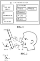
- FIG. 1 illustrates an exemplary electronic device 10 that includes a directional microphone array 12 and a plurality of sensors 20.
- the sensors 20 may include a 3D motion sensor 22 (e.g., accelerometer or velocity sensor), orientation sensor 24 (e.g., a gyroscope), Global Positioning System (GPS) module 26, one or more optical sensors 28 (e.g., cameras, visible light sensors, infrared sensors), and one or more proximity sensors 29.
- GPS Global Positioning System
- the electronic device 10 also includes a processor 30.
- the processor 30 includes a memory 31 that stores data to be used by software modules.
- the processor 30 is a signal processor.
- the microphones of the array 12 detect sound and output audio signals representing the sound.
- the processor 30 receives the audio signals, combines and processes the signals to create a virtual microphone.
- the processor 30 receives data from one or more of the sensors 20 and determines, based on the received data, the mode in which the electronic device 10 is being used.
- Such data includes one or more of the following: the movement of the electronic device 10 in any of the three dimensions (received from the motion sensor 22); the physical orientation of the device 10 (received from the orientation sensor 24); the terrestrial coordinates of the device 10 (received from the GPS module 26); photos or moving images of what is near the device 10 (received from the one or more optical sensors 28); and the presence of nearby objects or users (received from the one or more proximity sensors 29).
- the one or more proximity sensors 29 are configured into a proximity sensor array. Having a proximity sensor array allows the processor 30 to determine the distance to, and direction of a desired sound source with more accuracy than with a single proximity sensor.
- the processor 30 directionally orients the virtual microphone.
- the microphones of the array 12 do not need to be physically moved. Instead, the processor 30 combines and processes the audio signals in such a way as to beam steer the sensitivity of the microphones in the appropriate direction.
- the electronic device 10 maintains an optimal configuration for the microphones of the microphone array 12 in order to keep the virtual microphone oriented along the most appropriate vector. This can improve device usage in many respects, including voice recognition.
- the electronic device 10 may also include a permanent storage, a communications port for handling communications with external devices, and user interface devices.
- the software modules may be stored as program instructions or computer readable codes executable on the processor 30 on a computer-readable media such as read-only memory (ROM), random-access memory (RAM), and Digital Versatile Discs (DVDs).
- a sensor means any device that can sense and gather information about its environment. Possible types of information include the location in which the sensor is located, the status of the electronic device having the sensor included, and/or the spatial relationship between the electronic device and its user.
- the processor 30 changes the orientation of the virtual microphone quickly (e.g., nearly instantaneous) in order to minimize observable/audible artifacts. To do so, it uses an efficient technique for detecting the direction of the desired source (e.g., a particular speaker). Alternatively, the processor 30 knows the direction of the search a priori.
- the electronic device 10 minimizes power consumption by turning off one or more of the optical sensors 28 when they are not needed. Additionally, the device 10 does not run face feature recognition software during periods during which that feature is not needed.
- the processor 30 uses data received from the sensors 20 to determine a current use mode (use situation) of the electronic device 10.
- Possible use modes include: 1) stowed use mode in which the device is located within a bag, pocket, briefcase, or other enclosure; 2) handset (or private) mode in which the user is holding the device close to his/her ear/head; and 3) speakerphone mode in which the device is located at some distance away from the user and the earphone speaker is relatively inaudible.
- the processor 30 analyzes data it receives from one or more of the sensors 20.
- sensor information that may indicate a stowed use mode include (1) one or more of the optical sensors 28 (front, back, and other cameras or light sensors) detecting a low light level for more than a brief period of time; (2) the motion sensor 22 detecting motion consistent with being in a pants pocket or swinging in a handbag; and (3) the proximity sensor(s) 29 detecting multiple nearby surfaces.
- the processor 30 may consider any information indicating that the device 10 is within an enclosure.
- the processor 30 may use data from multiple sensors. In one embodiment, the processor 30 applies weighting factors to the different pieces of sensor data. For example, data from the orientation sensor 24 may indicate that the electronic device 10 is upside down from its normal use orientation. Although not conclusive, such data could carry more weight than other pieces of data in suggesting a stowed use mode. The processor 30 would also analyze data from other sensors 20 to determine whether it corroborates the orientation sensor.
- the processor 30 may analyze data from multiple optical sensors 28 and analyze the similarity of light observed among them. Similarly, the processor 30 can analyze data from multiple light sensors. Generally, the processor can use data from any combination of sensors, e.g., a combination of image data from the optical sensors 28, proximity data from the one or more proximity sensors 29, observed light data, etc.
- the processor 30 determines that the device 10 is in the stowed use mode, the processor 30 orients the virtual microphone so that it is not more or less sensitive in any particular direction. In other words, the processor 30 configures the virtual microphone to be omni-directional, as there may be no further information as to location of the user. In this situation, the overall gain of the microphone array 12 can be increased, the processor 30 can stop performing the tasks required for maintaining the virtual microphone, and/or the microphones of the array 12 can be turned off. The device 10 may take one or more of these actions based on a pre-programmed policy. Furthermore, the processor 30 can apply noise suppression algorithms that are appropriate for a stowed use mode. Alternatively, if the device 10 includes an omni-directional microphone, the signal processor 30 may turn off the directional microphones of the array 12, and solely use the omni-directional microphone.
- FIG. 2 illustrates a device 10 being used in the handheld (speakerphone) use mode.
- PH CS Physical Coordinate System
- WCS World Coordinate System
- the processor 30 uses data from one or more proximity sensors 29 to determine if the device 10 is in the handheld mode.
- the processor 30 may analyze data from the proximity sensors 29 or the optical sensor 28 to determine whether a user's head is within a certain distance of the device 10.
- the processor 30 determines the position and orientation of the device 10 relative to the WCS and relative to user's mouth 50 (the primary reference point) using data from the sensors 20. In one implementation, the processor 30 determines the primary reference point based on data from one or more of the cameras 28 or the one or more proximity sensors 29. In one embodiment, the one or more proximity sensors 29 are part of an array of proximity sensors. The use of a proximity sensor array enables the processor 30 to determine a more precise location of a desired talker in the handheld use mode. Having a more precise location allows the processor 30 to calculate a more accurate azimuth bearing. The processor 30 uses this azimuth bearing to orient the virtual microphone.
- the processor 30 can use data it receives from the 3D motion sensor 22 and/or orientation sensor 24 to maintain the position and orientation of the device 10 with respect to the initial position (and hence, the mouth 50 of the user).
- the approximate location of the desired speaker is known with accuracy of at least a hemisphere.
- the processor 30 can use this location data to orient the virtual microphone in that direction (see FIG. 2 ). Also, the processor 30 can use this information as initial estimate for a more elaborate search through space.
- the virtual microphone when the device 10 is in a first position 10a, the virtual microphone is oriented along a first vector 14a so that it is nearly perpendicular to the face of the device 10 facing the mouth 50 of the user.
- the spatial geometry of the virtual microphone is illustrated by a cardioid pattern 40.
- the movement is detected by one or more of the sensors 20 (e.g., the motion sensor 22 or orientation sensor 24).
- the processor 30 receives data from the one or more sensors indicating a change in position and, in response, reorients the virtual microphone to a second vector 14b
- the virtual microphone would have remained oriented nearly perpendicular to the primary face of the device facing the user.
- the device 10 has been moved to the second position 10b, but its orientation has not changed.
- the signal processor 30 needed to reorient the virtual microphone along a second vector 14b so that the virtual microphone would remain directed to the user's mouth 50.
- the processor 30 orients the virtual microphone based on data from the sensors 20 regarding the orientation of the device 10. In one example, the processor 30 orients the virtual microphone towards a location (or hemisphere) where desired talker (user's mouth) is. For example, if the device 10 is motionless and right side up with respect to the WCS, the virtual microphone is pointed up. If the device 10 is motionless and upside down (in the WCS) the processor 30 will orient the virtual microphone toward the back since the expected location of talker is in the back of the device 10. If the device is not motionless, then, based on the sensor 20 data, the processor 30 calculates device 10's orientation (pitch, yaw, roll) and calculates an orientation vector.
- the processor 30 calculates device 10's orientation (pitch, yaw, roll) and calculates an orientation vector.
- the processor 30 then reorients the virtual microphone along the calculated vector. While the position of the electronic device 10 is being tracked, the processor 30 periodically re-calibrates the initial reference point based on data obtained from camera 28 and/or proximity sensor 29 (or proximity sensor array). By establishing the initial positional and orientation relationship between the user and the device in this mode, the processor 30 can consistently direct the virtual microphone towards the user's mouth 50 in order to achieve the goals discussed above.
- the processor 30 orients the virtual microphone (i.e., steers the beam) at an angle relative to the horizontal plane (X-Z plane) of the WCS.
- the processor 30 accounts for the tilting of the device 10 by the user about any axis by reorienting the virtual microphone relative to the device 10, and doing so in a way that keeps the virtual microphone oriented such that it maintains a constant angle with respect to the horizontal plane of the WCS.
- the angle between the virtual microphone and the horizontal plane can be any angle, including zero, and can be modified by the user in a preset stored in the electronic device 10.
- the processor 30 would rotate the virtual microphone downward, i.e., in the Y direction about the X axis of the Ph CS in order to keep the virtual microphone at the same angle with respect to the horizontal plane of the WCS.
- FIGS. 3A-3C depict the electronic device 10 in the handset (also called "private") use mode.
- FIG. 3A and FIG. 3B show two views of a typical scenario, while FIG. 3C shows a less common scenario.
- the processor 30 uses data from one or more of the sensors 20. If the device 10 is determined to be in the handset mode, the processor 30 calculates the vector from the microphone array 12 and the desired talker's mouth 50. The processor 30 then tries to keep the virtual microphone oriented along that vector.
- the processor 30 can determine whether the electronic device 10 is in the handset use mode in a number of ways. For example, when one of the optical sensors 28 is implemented as a camera, it can be used to photograph an initial image of the environment. Using data received from the camera regarding the image, the processor 30 employs a facial feature recognition method to estimate (determine an approximate) distance between the device 10 and the face or facial feature (mouth 50, ear, or eye). If this distance is determined to be within a predefined threshold, then the processor 30 designates the device 10 as being in the handset use mode.
- the processor 30 can also use the proximity sensors 29 to determine distance and direction to the desired talker. The determination will be more accurate if the proximity sensors 29 are configured as an array.
- the device 10 is oriented so that its longitudinal axis AN will be at a known angle ON from a line normal to the horizontal plane of the WCS (line V).
- the virtual microphone of FIG. 3A can be oriented along a vector 15 that is normal to axis AN.
- the device 10 changes from its typical orientation ( FIG. 3A and FIG. 3B ) to a non-typical orientation ( FIG. 3C )
- the virtual microphone will need to be reoriented away from the initial position (i.e., away from where the mouth is expected to be in the typical use case).
- the device 10 moves from its typical position 11 ( FIG. 3A and FIG. 3B ) to a first non-typical position 11a.
- the primary axis A1 of the device 10 subtends a smaller angle ⁇ 1 than in the typical position.
- the processor 30 reacts to this change by reorienting the virtual microphone in an upward direction by changing its orientation vector from a first vector 15 to a second vector 15a. The purpose of this change is to ensure that the virtual microphone continues to point at the user's mouth 50.
- the device 10 moves from its typical position 11 ( FIG. 3A and FIG. 3B ) to a second non-typical position 11b.
- the primary axis A2 of the device 10 subtends a larger angle (180°- ⁇ 2 ) than in the typical position.
- the processor 30 reacts to this change by reorienting the virtual microphone in a downward direction by changing its orientation vector from a first vector 15 to a second vector 15b. Again, the purpose of this change is to ensure that the virtual microphone continues to point at the user's mouth 50.
- the beam steering algorithms i.e., the algorithms that the processor 30 uses to reorient the virtual microphone
- the processor 30 can use data from the sensors 20 to track the movement and change in orientation of the device 10 and reorient the virtual microphone (i.e., beam steer the array 12) accordingly.
- an optical sensor 28 is camera. The accelerometer 22, the orientation sensor 24, and the proximity sensors 29, are used for tracking, but the camera is not, as it may consume a significant amount of power from the device 10.
- the virtual microphone may be reoriented so that its orientation vector is steered towards the mouth reference point (MRP) in three dimensions as opposed to being constrained to being normal to axis AN.
- MRP vector orientation is calculated from known human anatomy and known positions, orientation and dimensions of the device 10.
- the processor 30 "orients" the virtual microphone by beam steering.
- the beam steering can be performed in one of two ways.
- One way which is illustrated in FIG. 4 , is to select and activate omni-directional microphone pairs.
- FIG. 4 there are three microphones A, B, C.
- AB, AC, and BC there are three pairs possible: AB, AC, and BC.
- Combining and processing the signals from each omnidirectional microphone pair creates directionality (gain) in a direction of a line connecting the two microphones.
- the gain direction ⁇ A-B, ⁇ A-C, and ⁇ B-C can be provided in a discrete switching and adjusting system.
- FIG. 5 Another way to beam steer is depicted in FIG. 5 , in which the inputs from all three omni-directional microphones A, B, C are incorporated.
- the processor 30 processes the input signals in order to achieve precise control over the overall direction ⁇ CONT of the microphone array. In carrying out this processing, the processor 30 could use a weighted sum of the signals from the individual virtual microphones, or could adjust delay functions or delay coefficients of two microphones from the third. These can be adjusted in a smooth fashion as a function of the desired direction.
- An advantage of the second technique over the first is that, using the first beam steering technique, the directionality is limited to discrete directions obtained by switching only. Using the second technique steers the beam continuously and smoothly, with exceptionally fine precision.
- Control over directionality can be achieved with as few as three non-collinear microphones. Any number of microphones could be used to achieve precise directional and/or gain characteristics, however. Furthermore, if a fourth microphone is added that is non-planar with the other three, movement in three dimensions can be achieved.
- the processor 30 receives data from the sensors 20, uses this data to make a decision about the orientation of the device 10 and the location (and therefore a direction of arrival) of the desired speech source. Once the processor establishes a hypothesis about the direction(s) of arrival of desired sound source, it configures the virtual microphone in accordance with the hypothesis. The processor carries this out by selecting which of the available microphones to activate, and how to combine their signals so as to obtain optimal virtual microphone configuration.
- the processor 30 can carry out additional processing on the signals from the sensors 20.
- the processor 30 can de-noise, threshold, or otherwise condition the signals in order to aid the processor in making the correct decision.
- the signal from the orientation sensor 24 may need to be filtered or long-term averaged in order to obtain stable vector information about the position of the device in space.
- Images from the optical sensors 28 may need to be processed to obtain basic information from them, such as how much light there is, and how consistent the detected light level is among multiple optical sensors.
- the processor 30 may also need to carry out more complex processing, such as correlating the lack of movement of the images on multiple optical sensors.
- FIG. 6 a system component block diagram illustrates a general flow of processing in the device 10 according to an embodiment of the disclosure.
- the sensors 20 are used to establish position / orientation of the device 10 via a portable orientation processor 32.
- This can be a part of the processor 30, incorporating program instructions to perform the orientation determination, or it could be a separate dedicated processor.
- the microphone configuration unit 34 uses the position/ orientation information in combination with the use case/mode determined for the device by the audio manager 36.
- the orientation vector of the virtual microphone can be continuously adjusted according to the microphone selection switch 13 and in the manner described above.
- Signal conditioning components 38 such as filtering and the like, can be applied to the signal received from the microphone array 38, and these conditioned signals can be provided to a voice recognition engine 39 or simply as enhanced audio input for the device.
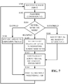
- FIG. 7 is a flowchart that illustrates a basic flow of operations described above according to one embodiment. Although the flowchart shows the steps as occurring in a particular order, the steps do not necessarily have to be performed in this order.
- the electronic device receives sensor input (S100), and may optionally perform conditioning (S102) on the sensor input signals received. With this sensor input, the device determines a use mode (S104). If the use mode is determined to be a stowed use mode, the microphone array is set to omnidirectional (S106) (alternatively S106 could be the deactivation of audio capture in the stowed mode), and the device performs subsequent post processing of the audio input (S114).
- S104 sensor input
- S106 omnidirectional
- S106 could be the deactivation of audio capture in the stowed mode
- the device adjusts the virtual microphone based on some form of sensed input (S108). Then, the device continuously adjusts the orientation vector of the virtual microphone based on sensor input (S112). The device then performs the subsequent post processing (S114). Finally, if the use mode is a handset mode, then the orientation vector of the virtual microphone is set to a predefined handset mode vector use direction (S110). The virtual microphone is continuously reoriented based on sensor input (S112) (although the algorithms may be different for the handset and the handheld mode). The device then further post processes the audio input (S114). This algorithm is repeatedly executed so that the correct mode is operative and the device uses the best way of adjusting the virtual microphone (beam steering the microphone array) in various situations.
- a “module” as used herein is software executing on hardware.
- a module may execute on multiple hardware elements or on a single one.
- the modules may, in fact, all be executing on the same device and in the same overall unit of software.
- the embodiments herein may be described in terms of functional block components and various processing steps. Such functional blocks may be realized by any number of hardware and/or software components that perform the specified functions.
- the described embodiments may employ various integrated circuit components, e.g., memory elements, processing elements, logic elements, look-up tables, and the like, which may carry out a variety of functions under the control of one or more microprocessors or other control devices.
- the elements of the described embodiments are implemented using software programming or software elements the disclosure may be implemented with any programming or scripting language such as C, C++, Java, assembler, or the like, with the various algorithms being implemented with any combination of data structures, objects, processes, routines or other programming elements.
- Functional aspects may be implemented in algorithms that execute on one or more processors.
- embodiments of the disclosure could employ any number of conventional techniques for electronics configuration, signal processing and/or control, data processing and the like.
- the words “mechanism” and “element” are used broadly and are not limited to mechanical or physical embodiments, but can include software routines in conjunction with processors, etc.
Landscapes
- Engineering & Computer Science (AREA)
- Signal Processing (AREA)
- Health & Medical Sciences (AREA)
- General Health & Medical Sciences (AREA)
- Otolaryngology (AREA)
- Physics & Mathematics (AREA)
- Acoustics & Sound (AREA)
- Circuit For Audible Band Transducer (AREA)
Claims (13)
- Verfahren zum Steuern der Ausrichtung eines virtuellen Mikrofons an einer elektronischen Vorrichtung, wobei das Verfahren umfasst:Kombinieren und Verarbeiten von Signalen von einer Mikrofongruppe zum Erzeugen des virtuellen Mikrofons;Empfangen von Daten von einem oder mehreren Sensoren der elektronischen Vorrichtung;wobei das Verfahren gekennzeichnet ist durch:Bestimmen, auf Grund der empfangenen Daten, ob die elektronische Vorrichtung in Folgenden verwendet wird:einem verstauten Verwendungsmodus, in dem die elektronische Vorrichtung durch das umgebende Material im Wesentlichen eingeschlossen ist; odereinem Handgerätmodus, in dem die elektronische Vorrichtung nahe einem Benutzer gehalten wird; odereinem handgehaltenen Verwendungsmodus, in dem die elektronische Vorrichtung von einem Benutzer weg gehalten wird; undAusrichten des virtuellen Mikrofons auf Grund des bestimmten Modus.
- Verfahren nach Anspruch 1,
wobei, wenn es sich bei dem bestimmten Verwendungsmodus um einen verstauten Verwendungsmodus handelt, das Ausrichten des virtuellen Mikrofons ein derartiges Ausrichten des virtuellen Mikrofons, dass es omnidirektional ist, oder ein Abschalten der Mikrofone der Mikrofongruppe umfasst. - Verfahren nach Anspruch 1,
wobei das Empfangen von Daten von dem einen oder den mehreren Sensoren der elektronischen Vorrichtung ein Empfangen von Ausrichtungsdaten von einem Ausrichtungssensor umfasst;
wobei, wenn es sich bei dem bestimmten Verwendungsmodus um einen Handgerätverwendungsmodus handelt, das Ausrichten des virtuellen Mikrofons ein Strahlformen der Mikrofongruppe in einer in einer Richtung, die senkrecht zu einer Längsachse der elektronischen Vorrichtung verläuft, auf Grund der Ausrichtungsdaten umfasst. - Verfahren nach Anspruch 1,
wobei das Empfangen von Daten von dem einen oder den mehreren Sensoren der elektronischen Vorrichtung ein Empfangen von Ausrichtungsdaten von einem Ausrichtungssensor umfasst;
wobei, wenn es sich bei dem bestimmten Verwendungsmodus um einen Handgerät-Verwendungsmodus handelt, das Verfahren ferner umfasst:Detektieren, mit dem Ausrichtungssensor, einer Bewegung der elektronischen Vorrichtung in Relation zu dem Kopf eines Benutzers aus einer ersten Ausrichtung in eine zweite Ausrichtung,wobei das Ausrichten des virtuellen Mikrofons ein kontinuierliches Kombinieren und Verarbeiten von Audiosignalen von der Mikrofongruppe umfasst, um ein Strahlformen in einer Richtung, die senkrecht zu einer Längsachse der elektronischen Vorrichtung verläuft, über die Bewegung hinweg von der ersten Ausrichtung in die zweite Ausrichtung vorzunehmen. - Verfahren nach Anspruch 4, wobei das kontinuierliche Kombinieren und Verarbeiten von Audiosignalen von der Mehrzahl an Mikrofonen umfasst:Anschalten eines ersten Paars und eines zweiten Paars Mikrofone aus der Mikrofongruppe, wobei das erste Paar und das zweite Paar Mikrofone wenigstens drei planare Mikrofone der Mikrofongruppe umfassen;Kombinieren einer ersten Mikrofonpaarausgabe mit einer zweiten Mikrofonpaarausgabe, sodass das Strahlformen der Mikrofone der Mikrofongruppe in eine Richtung erfolgt, welche senkrecht zu einer Längsachse der elektronischen Vorrichtung verläuft;und optional wobei das Verfahren ferner umfasst:Signalkonditionieren der ersten Mikrofonpaarausgabe und der zweiten Mikrofonpaarausgabe; undBereitstellen der signalkonditionierten Ausgaben an eine Spracherkennungsmaschine.
- Verfahren nach Anspruch 1,
wobei das Empfangen von Daten ein Empfangen realer Koordinatenausrichtungsdaten von dem Sensor umfasst;
wobei, wenn es sich bei dem bestimmten Verwendungsmodus um einen handgehaltenen Verwendungsmodus handelt, das Ausrichten des virtuellen Mikrofons ein Strahlformen der Mikrofone der Mikrofongruppe in einem Winkel in Relation zu einem Erdhorizont auf Grund der realen Koordinatenausrichtungsdaten umfasst;
wobei der Winkel durch den Benutzer konfigurierbar ist. - Elektronische Vorrichtung, umfassend:eine Mikrofongruppe, die eine Mehrzahl an Mikrofonen umfasst;einen oder mehrere Sensoren; unddie elektronische Vorrichtung ist dadurch gekennzeichnet, dass sie ferner umfasst:einen Prozessor, konfiguriert zum:Bestimmen, auf Grund von von dem einen oder den mehreren Sensoren empfangenen Daten, ob die elektronische Vorrichtung in Folgenden verwendet wird:einem verstauten Verwendungsmodus, in dem die elektronische Vorrichtung durch das umgebende Material im Wesentlichen eingeschlossen ist; odereinem Handgerätmodus, in dem die elektronische Vorrichtung nahe einem Benutzer gehalten wird; odereinem handgehaltenen Verwendungsmodus, in dem die elektronische Vorrichtung von einem Benutzer weg gehalten wird;wobei die Vorrichtung dazu konfiguriert ist, Signale von der Mikrofongruppe zu kombinieren und zu verarbeiten, um ein virtuelles Mikrofon zu erzeugen und das virtuelle Mikrofon auf Grund des bestimmten Modus auszurichten.
- Elektronische Vorrichtung nach Anspruch 7, wobei der Prozessor ferner dazu konfiguriert ist, eine erfasste Ausrichtung der elektronischen Vorrichtung in Relation zu einer bestimmten Kopfausrichtung eines Benutzers zu bestimmen.
- Elektronische Vorrichtung nach Anspruch 8, wobei:einer von dem/den Sensor(en) ein Bewegungsdetektionssensor ist, der eine Ausrichtungsbewegung der elektronischen Vorrichtung in Relation zu der Kopfausrichtung des Benutzers aus einer ersten Ausrichtung in eine zweite Ausrichtung detektiert; undder Prozessor dazu konfiguriert ist, die eine Empfangsausrichtung des virtuellen Mikrofons durch Strahlformen der Mikrofongruppe in eine Richtung, die senkrecht zu einer Längsachse der elektronischen Vorrichtung verläuft, über die Bewegung aus der ersten Ausrichtung in die zweite Ausrichtung hinweg einzustellen.
- Elektronische Vorrichtung nach Anspruch 9, wobei die Mikrofongruppe ferner umfasst:ein erstes Paar und ein zweites Paar Mikrofone, die jeweils entsprechende Ausgaben aufweisen, wobei das erste Paar und das zweite Paar Mikrofone wenigstens drei planare Mikrofone der Mikrofongruppe umfassen;wobei der Prozessor ferner konfiguriert ist zum:Kombinieren der ersten Mikrofonpaarausgabe mit der zweiten Mikrofonpaarausgabe, sodass die Empfangsausrichtung der Mikrofongruppe in eine Richtung erfolgt, welche senkrecht zu einer Längsachse der elektronischen Vorrichtung verläuft.
- Elektronische Vorrichtung nach Anspruch 7, wobei der Prozessor umfasst:eine Signalkonditionierungskomponente mit einem Eingang, der mit einem Ausgang der Mikrofongruppe verbunden ist;und optional wobei die elektronische Vorrichtung ferner eine Spracherkennungsmaschine umfasst, die konditionierte Signale von der Signalkonditionierungskomponente empfängt.
- Elektronische Vorrichtung nach Anspruch 7, wobei der eine oder die mehreren Sensoren einen oder mehrere von einem Nähesensor, einem Bewegungssensor, einem optischen Sensor und einem Ausrichtungssensor umfassen.
- Elektronische Vorrichtung nach Anspruch 7, wobei:der eine oder die mehreren Sensoren einen Ausrichtungssensor umfassen, der eine reale Koordinatenausrichtung der elektronischen Vorrichtung detektiert,wobei, wenn die elektronische Vorrichtung im handgehaltenen Verwendungsmodus ist, die Mikrofongruppe dazu konfiguriert ist, den Ausrichtungssensor zum Einstellen der Ausrichtung der Mikrofongruppe zu verwenden, damit sie sich in einer Richtung befindet, die senkrecht zu einer Längsachse der elektronischen Vorrichtung verläuft.
Applications Claiming Priority (5)
| Application Number | Priority Date | Filing Date | Title |
|---|---|---|---|
| US201361776793P | 2013-03-12 | 2013-03-12 | |
| US201361798097P | 2013-03-15 | 2013-03-15 | |
| US201361827722P | 2013-05-27 | 2013-05-27 | |
| US13/946,150 US9462379B2 (en) | 2013-03-12 | 2013-07-19 | Method and apparatus for detecting and controlling the orientation of a virtual microphone |
| PCT/US2014/014073 WO2014163739A1 (en) | 2013-03-12 | 2014-01-31 | Method and apparatus for detecting and controlling the orientation of a virtual microphone |
Publications (2)
| Publication Number | Publication Date |
|---|---|
| EP2974366A1 EP2974366A1 (de) | 2016-01-20 |
| EP2974366B1 true EP2974366B1 (de) | 2017-08-23 |
Family
ID=51527146
Family Applications (1)
| Application Number | Title | Priority Date | Filing Date |
|---|---|---|---|
| EP14704992.8A Not-in-force EP2974366B1 (de) | 2013-03-12 | 2014-01-31 | Verfahren und vorrichtung zum erfassen und steuern der ausrichtung eines virtuellen mikrofons |
Country Status (3)
| Country | Link |
|---|---|
| US (1) | US9462379B2 (de) |
| EP (1) | EP2974366B1 (de) |
| WO (1) | WO2014163739A1 (de) |
Families Citing this family (41)
| Publication number | Priority date | Publication date | Assignee | Title |
|---|---|---|---|---|
| US9084058B2 (en) | 2011-12-29 | 2015-07-14 | Sonos, Inc. | Sound field calibration using listener localization |
| US9106192B2 (en) | 2012-06-28 | 2015-08-11 | Sonos, Inc. | System and method for device playback calibration |
| CN104427049A (zh) * | 2013-08-30 | 2015-03-18 | 深圳富泰宏精密工业有限公司 | 便携式电子装置 |
| CN104464739B (zh) * | 2013-09-18 | 2017-08-11 | 华为技术有限公司 | 音频信号处理方法及装置、差分波束形成方法及装置 |
| US20150085615A1 (en) * | 2013-09-25 | 2015-03-26 | Lenovo (Singapore) Pte, Ltd. | Motion modified steering vector |
| US9432768B1 (en) | 2014-03-28 | 2016-08-30 | Amazon Technologies, Inc. | Beam forming for a wearable computer |
| CN103928025B (zh) * | 2014-04-08 | 2017-06-27 | 华为技术有限公司 | 一种语音识别的方法及移动终端 |
| US9609416B2 (en) * | 2014-06-09 | 2017-03-28 | Cirrus Logic, Inc. | Headphone responsive to optical signaling |
| US10609475B2 (en) | 2014-12-05 | 2020-03-31 | Stages Llc | Active noise control and customized audio system |
| US9712936B2 (en) * | 2015-02-03 | 2017-07-18 | Qualcomm Incorporated | Coding higher-order ambisonic audio data with motion stabilization |
| WO2016159938A1 (en) * | 2015-03-27 | 2016-10-06 | Hewlett-Packard Development Company, L.P. | Locating individuals using microphone arrays and voice pattern matching |
| US9565493B2 (en) * | 2015-04-30 | 2017-02-07 | Shure Acquisition Holdings, Inc. | Array microphone system and method of assembling the same |
| CN106604183B (zh) * | 2015-10-20 | 2020-06-26 | 华为终端有限公司 | 控制终端的多麦克风降噪的拾音范围的方法和装置 |
| US10095470B2 (en) | 2016-02-22 | 2018-10-09 | Sonos, Inc. | Audio response playback |
| US9947316B2 (en) | 2016-02-22 | 2018-04-17 | Sonos, Inc. | Voice control of a media playback system |
| US9763018B1 (en) | 2016-04-12 | 2017-09-12 | Sonos, Inc. | Calibration of audio playback devices |
| ITUA20164622A1 (it) * | 2016-06-23 | 2017-12-23 | St Microelectronics Srl | Procedimento di beamforming basato su matrici di microfoni e relativo apparato |
| CN106101365A (zh) * | 2016-06-29 | 2016-11-09 | 北京小米移动软件有限公司 | 通话过程中调整麦克风的方法及装置 |
| US10372406B2 (en) | 2016-07-22 | 2019-08-06 | Sonos, Inc. | Calibration interface |
| US9743204B1 (en) * | 2016-09-30 | 2017-08-22 | Sonos, Inc. | Multi-orientation playback device microphones |
| US9980042B1 (en) * | 2016-11-18 | 2018-05-22 | Stages Llc | Beamformer direction of arrival and orientation analysis system |
| US9980075B1 (en) | 2016-11-18 | 2018-05-22 | Stages Llc | Audio source spatialization relative to orientation sensor and output |
| US10945080B2 (en) | 2016-11-18 | 2021-03-09 | Stages Llc | Audio analysis and processing system |
| US11095978B2 (en) | 2017-01-09 | 2021-08-17 | Sonova Ag | Microphone assembly |
| US10366702B2 (en) | 2017-02-08 | 2019-07-30 | Logitech Europe, S.A. | Direction detection device for acquiring and processing audible input |
| US10366700B2 (en) | 2017-02-08 | 2019-07-30 | Logitech Europe, S.A. | Device for acquiring and processing audible input |
| US10362393B2 (en) | 2017-02-08 | 2019-07-23 | Logitech Europe, S.A. | Direction detection device for acquiring and processing audible input |
| US10229667B2 (en) | 2017-02-08 | 2019-03-12 | Logitech Europe S.A. | Multi-directional beamforming device for acquiring and processing audible input |
| US11288038B2 (en) | 2018-07-30 | 2022-03-29 | John Holst, III | System and method for voice recognition using a peripheral device |
| US10461710B1 (en) | 2018-08-28 | 2019-10-29 | Sonos, Inc. | Media playback system with maximum volume setting |
| US11218802B1 (en) * | 2018-09-25 | 2022-01-04 | Amazon Technologies, Inc. | Beamformer rotation |
| WO2021013346A1 (en) * | 2019-07-24 | 2021-01-28 | Huawei Technologies Co., Ltd. | Apparatus for determining spatial positions of multiple audio sources |
| US10771616B1 (en) | 2020-01-08 | 2020-09-08 | Motorola Mobility Llc | Methods and systems for stowed state verification in an electronic device |
| CN111148204A (zh) * | 2020-02-17 | 2020-05-12 | 深圳市广和通无线股份有限公司 | 发射功率调整方法、装置、计算机设备及存储介质 |
| US11277689B2 (en) | 2020-02-24 | 2022-03-15 | Logitech Europe S.A. | Apparatus and method for optimizing sound quality of a generated audible signal |
| US11586407B2 (en) | 2020-06-09 | 2023-02-21 | Meta Platforms Technologies, Llc | Systems, devices, and methods of manipulating audio data based on display orientation |
| US11620976B2 (en) | 2020-06-09 | 2023-04-04 | Meta Platforms Technologies, Llc | Systems, devices, and methods of acoustic echo cancellation based on display orientation |
| US11340861B2 (en) * | 2020-06-09 | 2022-05-24 | Facebook Technologies, Llc | Systems, devices, and methods of manipulating audio data based on microphone orientation |
| EP3996386B8 (de) | 2020-11-05 | 2025-10-22 | Audio-Technica U.S., Inc. | Mikrofon mit erweiterten funktionalitäten |
| CN113312971B (zh) * | 2021-04-25 | 2024-09-06 | 普联国际有限公司 | 麦克风阵列的参数标定方法、装置、终端设备及存储介质 |
| US12382219B1 (en) * | 2024-10-02 | 2025-08-05 | SimpliSafe, Inc. | Systems and methods for configuring duplexing within a doorbell camera |
Family Cites Families (11)
| Publication number | Priority date | Publication date | Assignee | Title |
|---|---|---|---|---|
| CN101015001A (zh) | 2004-09-07 | 2007-08-08 | 皇家飞利浦电子股份有限公司 | 提高了噪声抑制能力的电话装置 |
| US8676224B2 (en) | 2008-02-19 | 2014-03-18 | Apple Inc. | Speakerphone control for mobile device |
| US8285344B2 (en) | 2008-05-21 | 2012-10-09 | DP Technlogies, Inc. | Method and apparatus for adjusting audio for a user environment |
| US8285208B2 (en) | 2008-07-25 | 2012-10-09 | Apple Inc. | Systems and methods for noise cancellation and power management in a wireless headset |
| US9445193B2 (en) | 2008-07-31 | 2016-09-13 | Nokia Technologies Oy | Electronic device directional audio capture |
| US8548176B2 (en) | 2009-02-03 | 2013-10-01 | Nokia Corporation | Apparatus including microphone arrangements |
| EP2278356B1 (de) | 2009-07-02 | 2013-10-09 | Knowles Electronics Asia PTE. Ltd. | Vorrichtung und Verfahren zum Erkennen von Nutzungsprofilen in mobilen Vorrichtungen |
| EP2469828A1 (de) | 2010-12-23 | 2012-06-27 | Sony Ericsson Mobile Communications AB | Vorrichtung und Verfahren zur Erzeugung eines muffenkompensierten Ringsignals |
| US8525868B2 (en) | 2011-01-13 | 2013-09-03 | Qualcomm Incorporated | Variable beamforming with a mobile platform |
| US9264553B2 (en) | 2011-06-11 | 2016-02-16 | Clearone Communications, Inc. | Methods and apparatuses for echo cancelation with beamforming microphone arrays |
| US8781142B2 (en) * | 2012-02-24 | 2014-07-15 | Sverrir Olafsson | Selective acoustic enhancement of ambient sound |
-
2013
- 2013-07-19 US US13/946,150 patent/US9462379B2/en active Active
-
2014
- 2014-01-31 WO PCT/US2014/014073 patent/WO2014163739A1/en not_active Ceased
- 2014-01-31 EP EP14704992.8A patent/EP2974366B1/de not_active Not-in-force
Non-Patent Citations (1)
| Title |
|---|
| None * |
Also Published As
| Publication number | Publication date |
|---|---|
| US9462379B2 (en) | 2016-10-04 |
| EP2974366A1 (de) | 2016-01-20 |
| WO2014163739A1 (en) | 2014-10-09 |
| US20140270248A1 (en) | 2014-09-18 |
Similar Documents
| Publication | Publication Date | Title |
|---|---|---|
| EP2974366B1 (de) | Verfahren und vorrichtung zum erfassen und steuern der ausrichtung eines virtuellen mikrofons | |
| US11172292B2 (en) | Voice processing system | |
| JP7093872B2 (ja) | 適応レーダを備えるナビゲーションエイド | |
| EP3477964B1 (de) | Hörsystem mit konfiguration zum auffinden einer zielschallquelle | |
| EP3217653B1 (de) | Vorrichtung | |
| US20130121498A1 (en) | Noise reduction using microphone array orientation information | |
| US10244313B1 (en) | Beamforming for a wearable computer | |
| CN111402913B (zh) | 降噪方法、装置、设备和存储介质 | |
| US9525938B2 (en) | User voice location estimation for adjusting portable device beamforming settings | |
| EP4040808A1 (de) | Hörhilfesystem mit richtmikrofonanpassung | |
| US20140029761A1 (en) | Method and Apparatus for Microphone Beamforming | |
| US20180295462A1 (en) | Shoulder-mounted robotic speakers | |
| CN118020047A (zh) | 使用外部装置的电子装置及其运行方法 | |
| KR20250159737A (ko) | 마이크로폰 빔 스티어링이 있는 머리-착용형 컴퓨팅 장치 | |
| KR20240090752A (ko) | 시선-기반 오디오 빔포밍 | |
| US11632625B2 (en) | Sound modification based on direction of interest | |
| CN112995846A (zh) | 注意力集中辅助系统 | |
| EP3917160B1 (de) | Erfassen von inhalten | |
| WO2026022476A1 (en) | Walking aid | |
| GB2640340A (en) | Walking aid | |
| CN119790645A (zh) | 用于控制与外部电子装置的方向对应的显示器的电子装置、其操作方法及存储介质 | |
| WO2025146576A1 (en) | Horizontal and vertical conversation focusing using eye tracking | |
| WO2025146575A1 (en) | Gestures-based control of hearables |
Legal Events
| Date | Code | Title | Description |
|---|---|---|---|
| PUAI | Public reference made under article 153(3) epc to a published international application that has entered the european phase |
Free format text: ORIGINAL CODE: 0009012 |
|
| 17P | Request for examination filed |
Effective date: 20151008 |
|
| AK | Designated contracting states |
Kind code of ref document: A1 Designated state(s): AL AT BE BG CH CY CZ DE DK EE ES FI FR GB GR HR HU IE IS IT LI LT LU LV MC MK MT NL NO PL PT RO RS SE SI SK SM TR |
|
| AX | Request for extension of the european patent |
Extension state: BA ME |
|
| DAX | Request for extension of the european patent (deleted) | ||
| GRAP | Despatch of communication of intention to grant a patent |
Free format text: ORIGINAL CODE: EPIDOSNIGR1 |
|
| INTG | Intention to grant announced |
Effective date: 20170306 |
|
| GRAS | Grant fee paid |
Free format text: ORIGINAL CODE: EPIDOSNIGR3 |
|
| GRAA | (expected) grant |
Free format text: ORIGINAL CODE: 0009210 |
|
| AK | Designated contracting states |
Kind code of ref document: B1 Designated state(s): AL AT BE BG CH CY CZ DE DK EE ES FI FR GB GR HR HU IE IS IT LI LT LU LV MC MK MT NL NO PL PT RO RS SE SI SK SM TR |
|
| REG | Reference to a national code |
Ref country code: GB Ref legal event code: FG4D |
|
| REG | Reference to a national code |
Ref country code: CH Ref legal event code: EP |
|
| REG | Reference to a national code |
Ref country code: AT Ref legal event code: REF Ref document number: 922502 Country of ref document: AT Kind code of ref document: T Effective date: 20170915 |
|
| REG | Reference to a national code |
Ref country code: IE Ref legal event code: FG4D |
|
| REG | Reference to a national code |
Ref country code: DE Ref legal event code: R096 Ref document number: 602014013466 Country of ref document: DE |
|
| REG | Reference to a national code |
Ref country code: NL Ref legal event code: FP |
|
| REG | Reference to a national code |
Ref country code: LT Ref legal event code: MG4D |
|
| REG | Reference to a national code |
Ref country code: AT Ref legal event code: MK05 Ref document number: 922502 Country of ref document: AT Kind code of ref document: T Effective date: 20170823 |
|
| REG | Reference to a national code |
Ref country code: FR Ref legal event code: PLFP Year of fee payment: 5 |
|
| PG25 | Lapsed in a contracting state [announced via postgrant information from national office to epo] |
Ref country code: FI Free format text: LAPSE BECAUSE OF FAILURE TO SUBMIT A TRANSLATION OF THE DESCRIPTION OR TO PAY THE FEE WITHIN THE PRESCRIBED TIME-LIMIT Effective date: 20170823 Ref country code: SE Free format text: LAPSE BECAUSE OF FAILURE TO SUBMIT A TRANSLATION OF THE DESCRIPTION OR TO PAY THE FEE WITHIN THE PRESCRIBED TIME-LIMIT Effective date: 20170823 Ref country code: LT Free format text: LAPSE BECAUSE OF FAILURE TO SUBMIT A TRANSLATION OF THE DESCRIPTION OR TO PAY THE FEE WITHIN THE PRESCRIBED TIME-LIMIT Effective date: 20170823 Ref country code: HR Free format text: LAPSE BECAUSE OF FAILURE TO SUBMIT A TRANSLATION OF THE DESCRIPTION OR TO PAY THE FEE WITHIN THE PRESCRIBED TIME-LIMIT Effective date: 20170823 Ref country code: AT Free format text: LAPSE BECAUSE OF FAILURE TO SUBMIT A TRANSLATION OF THE DESCRIPTION OR TO PAY THE FEE WITHIN THE PRESCRIBED TIME-LIMIT Effective date: 20170823 Ref country code: NO Free format text: LAPSE BECAUSE OF FAILURE TO SUBMIT A TRANSLATION OF THE DESCRIPTION OR TO PAY THE FEE WITHIN THE PRESCRIBED TIME-LIMIT Effective date: 20171123 |
|
| PG25 | Lapsed in a contracting state [announced via postgrant information from national office to epo] |
Ref country code: PL Free format text: LAPSE BECAUSE OF FAILURE TO SUBMIT A TRANSLATION OF THE DESCRIPTION OR TO PAY THE FEE WITHIN THE PRESCRIBED TIME-LIMIT Effective date: 20170823 Ref country code: LV Free format text: LAPSE BECAUSE OF FAILURE TO SUBMIT A TRANSLATION OF THE DESCRIPTION OR TO PAY THE FEE WITHIN THE PRESCRIBED TIME-LIMIT Effective date: 20170823 Ref country code: IS Free format text: LAPSE BECAUSE OF FAILURE TO SUBMIT A TRANSLATION OF THE DESCRIPTION OR TO PAY THE FEE WITHIN THE PRESCRIBED TIME-LIMIT Effective date: 20171223 Ref country code: RS Free format text: LAPSE BECAUSE OF FAILURE TO SUBMIT A TRANSLATION OF THE DESCRIPTION OR TO PAY THE FEE WITHIN THE PRESCRIBED TIME-LIMIT Effective date: 20170823 Ref country code: ES Free format text: LAPSE BECAUSE OF FAILURE TO SUBMIT A TRANSLATION OF THE DESCRIPTION OR TO PAY THE FEE WITHIN THE PRESCRIBED TIME-LIMIT Effective date: 20170823 Ref country code: GR Free format text: LAPSE BECAUSE OF FAILURE TO SUBMIT A TRANSLATION OF THE DESCRIPTION OR TO PAY THE FEE WITHIN THE PRESCRIBED TIME-LIMIT Effective date: 20171124 Ref country code: BG Free format text: LAPSE BECAUSE OF FAILURE TO SUBMIT A TRANSLATION OF THE DESCRIPTION OR TO PAY THE FEE WITHIN THE PRESCRIBED TIME-LIMIT Effective date: 20171123 |
|
| PG25 | Lapsed in a contracting state [announced via postgrant information from national office to epo] |
Ref country code: RO Free format text: LAPSE BECAUSE OF FAILURE TO SUBMIT A TRANSLATION OF THE DESCRIPTION OR TO PAY THE FEE WITHIN THE PRESCRIBED TIME-LIMIT Effective date: 20170823 Ref country code: DK Free format text: LAPSE BECAUSE OF FAILURE TO SUBMIT A TRANSLATION OF THE DESCRIPTION OR TO PAY THE FEE WITHIN THE PRESCRIBED TIME-LIMIT Effective date: 20170823 Ref country code: CZ Free format text: LAPSE BECAUSE OF FAILURE TO SUBMIT A TRANSLATION OF THE DESCRIPTION OR TO PAY THE FEE WITHIN THE PRESCRIBED TIME-LIMIT Effective date: 20170823 |
|
| REG | Reference to a national code |
Ref country code: DE Ref legal event code: R097 Ref document number: 602014013466 Country of ref document: DE |
|
| PG25 | Lapsed in a contracting state [announced via postgrant information from national office to epo] |
Ref country code: SK Free format text: LAPSE BECAUSE OF FAILURE TO SUBMIT A TRANSLATION OF THE DESCRIPTION OR TO PAY THE FEE WITHIN THE PRESCRIBED TIME-LIMIT Effective date: 20170823 Ref country code: SM Free format text: LAPSE BECAUSE OF FAILURE TO SUBMIT A TRANSLATION OF THE DESCRIPTION OR TO PAY THE FEE WITHIN THE PRESCRIBED TIME-LIMIT Effective date: 20170823 Ref country code: IT Free format text: LAPSE BECAUSE OF FAILURE TO SUBMIT A TRANSLATION OF THE DESCRIPTION OR TO PAY THE FEE WITHIN THE PRESCRIBED TIME-LIMIT Effective date: 20170823 Ref country code: EE Free format text: LAPSE BECAUSE OF FAILURE TO SUBMIT A TRANSLATION OF THE DESCRIPTION OR TO PAY THE FEE WITHIN THE PRESCRIBED TIME-LIMIT Effective date: 20170823 |
|
| PLBE | No opposition filed within time limit |
Free format text: ORIGINAL CODE: 0009261 |
|
| STAA | Information on the status of an ep patent application or granted ep patent |
Free format text: STATUS: NO OPPOSITION FILED WITHIN TIME LIMIT |
|
| 26N | No opposition filed |
Effective date: 20180524 |
|
| PG25 | Lapsed in a contracting state [announced via postgrant information from national office to epo] |
Ref country code: SI Free format text: LAPSE BECAUSE OF FAILURE TO SUBMIT A TRANSLATION OF THE DESCRIPTION OR TO PAY THE FEE WITHIN THE PRESCRIBED TIME-LIMIT Effective date: 20170823 |
|
| REG | Reference to a national code |
Ref country code: CH Ref legal event code: PL |
|
| PG25 | Lapsed in a contracting state [announced via postgrant information from national office to epo] |
Ref country code: LU Free format text: LAPSE BECAUSE OF NON-PAYMENT OF DUE FEES Effective date: 20180131 |
|
| REG | Reference to a national code |
Ref country code: BE Ref legal event code: MM Effective date: 20180131 |
|
| PG25 | Lapsed in a contracting state [announced via postgrant information from national office to epo] |
Ref country code: BE Free format text: LAPSE BECAUSE OF NON-PAYMENT OF DUE FEES Effective date: 20180131 Ref country code: LI Free format text: LAPSE BECAUSE OF NON-PAYMENT OF DUE FEES Effective date: 20180131 Ref country code: CH Free format text: LAPSE BECAUSE OF NON-PAYMENT OF DUE FEES Effective date: 20180131 |
|
| PG25 | Lapsed in a contracting state [announced via postgrant information from national office to epo] |
Ref country code: MC Free format text: LAPSE BECAUSE OF FAILURE TO SUBMIT A TRANSLATION OF THE DESCRIPTION OR TO PAY THE FEE WITHIN THE PRESCRIBED TIME-LIMIT Effective date: 20170823 |
|
| PG25 | Lapsed in a contracting state [announced via postgrant information from national office to epo] |
Ref country code: MT Free format text: LAPSE BECAUSE OF NON-PAYMENT OF DUE FEES Effective date: 20180131 |
|
| PG25 | Lapsed in a contracting state [announced via postgrant information from national office to epo] |
Ref country code: TR Free format text: LAPSE BECAUSE OF FAILURE TO SUBMIT A TRANSLATION OF THE DESCRIPTION OR TO PAY THE FEE WITHIN THE PRESCRIBED TIME-LIMIT Effective date: 20170823 |
|
| PG25 | Lapsed in a contracting state [announced via postgrant information from national office to epo] |
Ref country code: PT Free format text: LAPSE BECAUSE OF FAILURE TO SUBMIT A TRANSLATION OF THE DESCRIPTION OR TO PAY THE FEE WITHIN THE PRESCRIBED TIME-LIMIT Effective date: 20170823 |
|
| PG25 | Lapsed in a contracting state [announced via postgrant information from national office to epo] |
Ref country code: CY Free format text: LAPSE BECAUSE OF FAILURE TO SUBMIT A TRANSLATION OF THE DESCRIPTION OR TO PAY THE FEE WITHIN THE PRESCRIBED TIME-LIMIT Effective date: 20170823 Ref country code: MK Free format text: LAPSE BECAUSE OF NON-PAYMENT OF DUE FEES Effective date: 20170823 Ref country code: HU Free format text: LAPSE BECAUSE OF FAILURE TO SUBMIT A TRANSLATION OF THE DESCRIPTION OR TO PAY THE FEE WITHIN THE PRESCRIBED TIME-LIMIT; INVALID AB INITIO Effective date: 20140131 |
|
| PG25 | Lapsed in a contracting state [announced via postgrant information from national office to epo] |
Ref country code: AL Free format text: LAPSE BECAUSE OF FAILURE TO SUBMIT A TRANSLATION OF THE DESCRIPTION OR TO PAY THE FEE WITHIN THE PRESCRIBED TIME-LIMIT Effective date: 20170823 |
|
| P01 | Opt-out of the competence of the unified patent court (upc) registered |
Effective date: 20230510 |
|
| PGFP | Annual fee paid to national office [announced via postgrant information from national office to epo] |
Ref country code: NL Payment date: 20240126 Year of fee payment: 11 |
|
| PGFP | Annual fee paid to national office [announced via postgrant information from national office to epo] |
Ref country code: IE Payment date: 20240129 Year of fee payment: 11 |
|
| PGFP | Annual fee paid to national office [announced via postgrant information from national office to epo] |
Ref country code: DE Payment date: 20240129 Year of fee payment: 11 Ref country code: GB Payment date: 20240129 Year of fee payment: 11 |
|
| PGFP | Annual fee paid to national office [announced via postgrant information from national office to epo] |
Ref country code: FR Payment date: 20240125 Year of fee payment: 11 |
|
| REG | Reference to a national code |
Ref country code: DE Ref legal event code: R119 Ref document number: 602014013466 Country of ref document: DE |
|
| REG | Reference to a national code |
Ref country code: NL Ref legal event code: MM Effective date: 20250201 |
|
| GBPC | Gb: european patent ceased through non-payment of renewal fee |
Effective date: 20250131 |
|
| PG25 | Lapsed in a contracting state [announced via postgrant information from national office to epo] |
Ref country code: DE Free format text: LAPSE BECAUSE OF NON-PAYMENT OF DUE FEES Effective date: 20250801 |
|
| PG25 | Lapsed in a contracting state [announced via postgrant information from national office to epo] |
Ref country code: NL Free format text: LAPSE BECAUSE OF NON-PAYMENT OF DUE FEES Effective date: 20250201 |
|
| PG25 | Lapsed in a contracting state [announced via postgrant information from national office to epo] |
Ref country code: GB Free format text: LAPSE BECAUSE OF NON-PAYMENT OF DUE FEES Effective date: 20250131 |
|
| PG25 | Lapsed in a contracting state [announced via postgrant information from national office to epo] |
Ref country code: FR Free format text: LAPSE BECAUSE OF NON-PAYMENT OF DUE FEES Effective date: 20250131 |
|
| PG25 | Lapsed in a contracting state [announced via postgrant information from national office to epo] |
Ref country code: IE Free format text: LAPSE BECAUSE OF NON-PAYMENT OF DUE FEES Effective date: 20250131 |