EP2974359B1 - Ear jewelry with wireless audio device - Google Patents
Ear jewelry with wireless audio device Download PDFInfo
- Publication number
- EP2974359B1 EP2974359B1 EP13877941.8A EP13877941A EP2974359B1 EP 2974359 B1 EP2974359 B1 EP 2974359B1 EP 13877941 A EP13877941 A EP 13877941A EP 2974359 B1 EP2974359 B1 EP 2974359B1
- Authority
- EP
- European Patent Office
- Prior art keywords
- sound
- audio device
- unit
- ear
- production
- Prior art date
- Legal status (The legal status is an assumption and is not a legal conclusion. Google has not performed a legal analysis and makes no representation as to the accuracy of the status listed.)
- Not-in-force
Links
Images





Classifications
-
- H—ELECTRICITY
- H04—ELECTRIC COMMUNICATION TECHNIQUE
- H04R—LOUDSPEAKERS, MICROPHONES, GRAMOPHONE PICK-UPS OR LIKE ACOUSTIC ELECTROMECHANICAL TRANSDUCERS; ELECTRIC HEARING AIDS; PUBLIC ADDRESS SYSTEMS
- H04R1/00—Details of transducers, loudspeakers or microphones
- H04R1/10—Earpieces; Attachments therefor ; Earphones; Monophonic headphones
- H04R1/105—Earpiece supports, e.g. ear hooks
-
- H—ELECTRICITY
- H04—ELECTRIC COMMUNICATION TECHNIQUE
- H04R—LOUDSPEAKERS, MICROPHONES, GRAMOPHONE PICK-UPS OR LIKE ACOUSTIC ELECTROMECHANICAL TRANSDUCERS; ELECTRIC HEARING AIDS; PUBLIC ADDRESS SYSTEMS
- H04R1/00—Details of transducers, loudspeakers or microphones
- H04R1/02—Casings; Cabinets ; Supports therefor; Mountings therein
- H04R1/028—Casings; Cabinets ; Supports therefor; Mountings therein associated with devices performing functions other than acoustics, e.g. electric candles
-
- H—ELECTRICITY
- H04—ELECTRIC COMMUNICATION TECHNIQUE
- H04R—LOUDSPEAKERS, MICROPHONES, GRAMOPHONE PICK-UPS OR LIKE ACOUSTIC ELECTROMECHANICAL TRANSDUCERS; ELECTRIC HEARING AIDS; PUBLIC ADDRESS SYSTEMS
- H04R1/00—Details of transducers, loudspeakers or microphones
- H04R1/10—Earpieces; Attachments therefor ; Earphones; Monophonic headphones
- H04R1/1058—Manufacture or assembly
- H04R1/1066—Constructional aspects of the interconnection between earpiece and earpiece support
-
- H—ELECTRICITY
- H04—ELECTRIC COMMUNICATION TECHNIQUE
- H04R—LOUDSPEAKERS, MICROPHONES, GRAMOPHONE PICK-UPS OR LIKE ACOUSTIC ELECTROMECHANICAL TRANSDUCERS; ELECTRIC HEARING AIDS; PUBLIC ADDRESS SYSTEMS
- H04R2201/00—Details of transducers, loudspeakers or microphones covered by H04R1/00 but not provided for in any of its subgroups
- H04R2201/003—Mems transducers or their use
-
- H—ELECTRICITY
- H04—ELECTRIC COMMUNICATION TECHNIQUE
- H04R—LOUDSPEAKERS, MICROPHONES, GRAMOPHONE PICK-UPS OR LIKE ACOUSTIC ELECTROMECHANICAL TRANSDUCERS; ELECTRIC HEARING AIDS; PUBLIC ADDRESS SYSTEMS
- H04R2201/00—Details of transducers, loudspeakers or microphones covered by H04R1/00 but not provided for in any of its subgroups
- H04R2201/02—Details casings, cabinets or mounting therein for transducers covered by H04R1/02 but not provided for in any of its subgroups
- H04R2201/023—Transducers incorporated in garment, rucksacks or the like
-
- H—ELECTRICITY
- H04—ELECTRIC COMMUNICATION TECHNIQUE
- H04R—LOUDSPEAKERS, MICROPHONES, GRAMOPHONE PICK-UPS OR LIKE ACOUSTIC ELECTROMECHANICAL TRANSDUCERS; ELECTRIC HEARING AIDS; PUBLIC ADDRESS SYSTEMS
- H04R2420/00—Details of connection covered by H04R, not provided for in its groups
- H04R2420/07—Applications of wireless loudspeakers or wireless microphones
Definitions
- piercing of various parts of the body for insertion of jewelry has been conducted by humans for thousands of years for a variety of reasons. Some piercings are completed for religious or spiritual beliefs and ceremonies while others are for ornamental purposes. The most common piercings are those in lobes of the ears, but a variety of other locations both in different parts of the ear as well as other parts of the body are not uncommon. For example, ear piercings are commonly formed in cartilaginous parts of the ear like the helix, concha, or tragus, among others.
- Common earrings include a thin stud that is inserted through the lobe of the ear and retained in place by a clutch installed thereon.
- some subcultures or piercing "purists" employ larger body jewelry that requires or forms much larger piercings in the lobe or other portions of the ear.
- the body jewelry worn in these piercings is often held in place without the use of a clutch or other fastener and may require insertion into a piercing by stretching the piercing to allow passage of an enlarged end of the jewelry and then allowing the piercing to shrink or return to an original size to retain the jewelry therein.
- an industrial piercing One type of body jewelry that is often used in cartilaginous parts of the ears is referred to as an industrial piercing.
- the industrial comprises an elongate rod with enlarged ends that is typically disposed to extend through a pair of piercings in the upper portion of the ear.
- Another form or variation of an industrial piercing is a spiral piercing which includes a spiral shaped body that is disposed in two or more piercings in the ear and may spiral or wrap around an edge or the scapha of the ear.
- Gauge-style earrings comprise piercings in which a small initial piercing is created through, for example, the lobe of the ear. The piercing is then expanded or stretched over time by placing incrementally larger earrings therein. These earrings are referred to by their diametrical size measured using the American Wire Gauge (AWG) standard or in millimeters. Such earrings include those referred to as a taper and a gauge.
- a taper typically includes a body that is larger at one end than the other. An enlarged ball or similar feature may be disposed at the point thereof. The taper may be employed to slowly expand the piercing.
- Gauge-style earrings generally comprise a ring, also known as a tunnel, or a plug that is disposed within the piercing.
- U.S. Patent No. 8,086,288 to Klein describes a wireless earring headset that is attached to the lobe of a user's ear via a stud extending through a small piercing in the user's ear and held in place by a clutch or clasp coupled to the stud.
- the headset includes a speaker that is directed toward the user's ear canal and a microphone disposed on a boom directed toward the user's mouth. This configuration with the large body and the microphone boom extending therefrom may be found by users to be bulky and unattractive for wearing in public or in a social setting.
- U.S. Patent No. 7,536,150 to Ryann describes a wireless earpiece assembly configured to give the appearance of an earring.
- the assembly is attached to the lobe of the user's ear via a stud or clasp which fully supports the assembly. Other contact with the ear is avoided to reduce discomfort caused by long-term use.
- the assembly includes a coupling mechanism or hoop on which a speaker and a casing are disposed.
- the speaker is positioned to direct sound toward the user's ear canal and the casing is suspended from the coupling mechanism and houses operational components of the assembly.
- the configuration described by the '150 patent is ostensibly designed to resemble an earring, the speaker is fully visible and disposed adjacent the ear of the user during wearing of the assembly.
- U.S. Patent Application Publication No. 2012/0308069 to Stott describes a gauge-style piercing with a speaker disposed therein.
- the speaker is directed outwardly and away from the user's ear to enable the user to hear audio outputs therefrom while also retaining the ability to hear sounds from their surroundings and environment.
- the '069 publication teaches that such a configuration is necessary to ensure the safety of the user and to avoid bulky or uncomfortable headphones that are placed in the user's ear canal and that block out environmental noises.
- Such a configuration broadcasts the audio outputs to the user's surroundings which may be unwanted by the user or by those nearby.
- US 5,828,757 discloses an audio device worn in a piercing in a user's ear comprising an elongate body having a first end and an opposite second end, the body is adapted to be disposed to extend through a piercing in a ear of a user, the audio device further comprising a communication component in the sound-production unit coupled to the first end of the body.
- the audio device is completely arranged at the outside side of the ear-lobe and fixed to the ear by post and backing member.
- a comparably audio device is disclosed in US 2008/03311966 A1 . This audio device shows the further feature, that the backing member contains a battery and electrical energy for the audio device is provided through the post.
- the invention is defined by the subject-matter of claim 1.
- the device includes a body with a wireless communications unit and a sound-production unit, such as a speaker or transducer coupled thereto.
- the wireless communications unit is connected to a first end of the body and transmits audio output signals through the body to the sound-production unit.
- the sound-production unit is coupled to the opposite second end of the body via a flexible conduit to allow the sound-production unit to be placed in proximity to or at least partially in the ear canal of the user when listening to audio output.
- the sound-production unit can be covered by an ornamental cover and suspended from the second end of the body or disposed within the body.
- the wireless communications unit may be detachable from the body to enable a wired connection to be made to the body.
- the wireless communication unit, the body, and/or the sound-production unit might also include one or more input surfaces that can be manipulated by a user to control a master device that is coupled thereto.
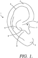
- the pinna 1 comprises a soft appendage generally comprised of cartilage and soft or fleshy tissues that collect and direct sound toward the ear canal 2 for receipt by the inner ear as known in the art.
- a variety of portions of the pinna 1 may be pierced for insertion of body jewelry.
- the lobe 3 comprises fleshy tissues such as skin, and may be pierced for insertion of an earring or body jewelry such as a taper- or gauge-style earring.
- earrings and body jewelry that are insertable in a piercing in the pinna 1 are collectively referred to as earrings.
- the helix 4, scapha 5, antihelix 6, tragus 7, concha 8, and antitragus 9 are a cartilaginous portions of the pinna 1 that can be pierced for insertion of earrings known as an industrial, spiral, rook, tragus, and conch, among others.
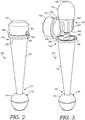
- the audio device 100 is configured as a taper-style earring and includes a body 110 having a generally conical form.
- the conical form provides a first end 112 of the body 110 with dimensions that are smaller than those of an opposite second end 114.
- the body 110 is described herein as including a linear or straight conical taper-style form, it is to be understood that the body 110 can take a variety of different taper-style forms including for example, curved, spiral, claw, or horn shaped tapers among others.
- the body 110 includes a substantially hollow interior space and is removeably coupled at the first end 112 to a control unit 116.
- the control unit 116 includes a housing 118 having dimensions larger than the first end 112 of the body 110, e.g. the housing 118 has a diameter that is larger than the diameter of the first end 112 of the body 110, but the housing 118 can have any desired dimensions-larger or smaller than those of the body 110.
- the housing 118 is preferably configured in a spheroidal form but any desired form can be employed. The size and shape of the housing 118 may aid in avoiding inadvertent withdrawal of the audio device 100 from the piercing. Other components might also or alternatively be employed to avoid inadvertent withdrawal and/or to maintain positioning of the body 110 in the piercing, such as rubber o-rings.
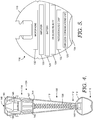
- a variety of components are disposed in the housing 118 and configured for operation of the audio device 100 including a wireless communications unit 120, a processor or logic chip 122, an on-board memory 124, and a battery 128.
- An amplifier 130 and a microphone 132 might also be included, among a variety of other components. It is to be understood that one or more of these components can be combined or their functions performed by another component.
- processors can include memory. Additionally, detail of the connections and communications between the components is not necessary for conveying an understanding of embodiments of the invention and is not described in detail herein.
- the wireless communications unit 120 employs wireless communications protocols, standards, hardware, and the like, available in the art, such as, for example, the BLUETOOTH standards developed by the Bluetooth Special Interest Group. As shown in FIG. 7 , the wireless communications unit 120 in the control unit 116 provides wireless communications between the audio device 100 and a master device 133 such as a digital music player, a cellular telephone, a computer, or similar electronic device. The master device 133 provides audio data, and control signals, among other communications to the audio device 100 via wireless communications with the wireless communications unit 120 for use by the audio device 100.
- a master device 133 such as a digital music player, a cellular telephone, a computer, or similar electronic device.
- the master device 133 provides audio data, and control signals, among other communications to the audio device 100 via wireless communications with the wireless communications unit 120 for use by the audio device 100.
- the audio device 100 may also transmit a variety of communications to the master device 133 via the wireless communications unit 120 like, for example, handshake signaling for creating a secure connection therebetween, audio data collected by the microphone 132, or command signals to the master device 133, e.g. to change an audio file being played, among others.
- a variety of communications to the master device 133 via the wireless communications unit 120 like, for example, handshake signaling for creating a secure connection therebetween, audio data collected by the microphone 132, or command signals to the master device 133, e.g. to change an audio file being played, among others.
- the processor or logic chip 122 executes one or more programs or routines useable to produce an audible output using audio data received from the master device 133 via the wireless communications device 120.
- the processor 122 may process audio inputs received from the microphone 132 for communication to the master device 133.
- one or more control surfaces 134 can be provided on the audio device 100 from which the processor 122 can receive input commands.
- the control surfaces 134 can include touch interfaces, such as capacitive surfaces, buttons, switches, rotatory dials, or the like and enable a user to provide inputs to the audio device 100 or to the master device 133.
- a capacitive touch interface is provided in a base or distal end of the housing 118.
- a lower portion of the housing 118 is rotatable with respect to an upper portion or with respect to the body 110 to provide input to the audio device 100 or to the master controller. For example, a user might provide an input to change an audio track being played, to increase a volume of the audio output, or to interact with an application executing on the master device 133.
- the on-board memory 124 is useable by the processor 122 for execution of programs and routines but is not configured to provide storage of audio or other data for later playback, e.g. the memory 124 cannot be used to store audio data for a plurality of songs on the audio device 100 for later playback in a manner similar to a digital music player-such tasks are reserved for the master device 133.
- the memory 124 can be configured for storage of one or more data or audio files.
- the amplifier 130 is employed by the processor 122 to provide outputs useable by a sound-production unit 136 disposed proximate the second end 114 of the body 110.
- the output of the amplifier 130 comprises electrical signals, which may be amplified, that are communicated to the sound-production unit 136 via an electrical wire or conductor 138 in a known manner.
- the control unit 116 might also be configured to provide outputs to the sound-production unit 136 as air pressure waves carried by a hollow conduit, or as light rays carried by fiberoptic conduits.
- the body 110 functions as the electrical wire or conductor 138 (see FIG. 14D ) or as the conduit for carrying the pressure waves or optical signals.
- the microphone 132 is any available microphone useable to receive audio inputs from a user including, for example, vocalizations provided during a telephone call as well as voice commands to the master device 133 when such capabilities are present in the master device 133. Additional microphones 132 may be provided at disparate locations on the audio device 100 for use in collecting audio inputs from a user's surroundings or environment, such as in the body 110 or in the sound-production unit 136. Such audio inputs are useable by the processor 122 or the master device 133 for noise cancellation among other uses.
- the control unit 116 is removeably coupled to the first end 112 of the body 110.
- the coupling can be a threaded coupling provided by mating threads on the first end 112 of the body 110 and a receptacle 140 in the housing 118 of the control unit 116.
- the body 110 and the housing 118 can include any of a variety of mating flanges, tabs, grooves, slots, or the like that enable snap-fit, friction-fit, magnetic fit, or other engageable couplings.
- the coupling places the control unit 116 in communication with the conductor 138 by, for example, placing metallic contacts on the first end 112 of the body 110 in contact with mating contacts disposed within the receptacle 140 of the housing 118.
- the first end 112 of the body 110 may also be configured to receive a wire 141 or other conductor for connection to the master device 133 when the control unit 116 is removed therefrom.
- the threads, flanges, tabs, or other features on the first end 112 of the body 110 for coupling to the housing 118 of the control unit 116 as well as the contacts for coupling to the conductor 138 can be employed for coupling with a receiver 139 on an end of a wire 141.
- Such a wired coupling might be employed when wireless communications are restricted, e.g. such as on an airplane, but use of the audio device 100 is desired.
- the conductor 138 is coupled to the first end 112 of the body 110 within the interior thereof and extends through the interior of the body 110 toward the second end 114 and couples to the sound-production unit 136.
- the conductor 138 is flexible and may be extensible to enable the conductor 138 to extend a distance from within the body 110 sufficient to place a distal end of the sound-production unit 136 in proximity to the ear canal 2 of a user wearing the audio device 100 in the pinna 1 of the user's ear.
- the sound-production unit 136 is disposed in the pinna 1 in a space defined by the antihelix 6, concha 8, and tragus 7 and is directed toward or into the ear canal 2.
- the conductor 138 is provided in a spiral or helical configuration to provide sufficient length to the conductor 138 while also enabling retraction of the conductor 138 into the body 110.
- the conductor 138 can alternatively be provided in any desired configuration that enables extension and retraction thereof as described herein.
- the conductor 138 might be disposed on a coil or spool within the body 110 that feeds out the conductor 138 when needed.
- the conductor 138 may have a memory or may be coated with a resilient coating having a memory to at least partially bias the conductor 138 toward the retracted, spiraled configuration. Such may aid retraction of the conductor 138 into the body 110 when desired.
- the sound-production unit 136 includes a housing 142 comprising a base 144 with a nipple 146 extending from a distal end thereof.
- the sound-production unit 136 includes a speaker, transducer, driver, or other sound production components (hereinafter referred to generally as a speaker) disposed in the housing 142 and configured to produce an audible output.
- Other components such as an amplifier, microphone, or the like might also be disposed in the sound-production unit 136.
- the base 144 of the sound-production unit 136 housing 142 is configured with a frusto-conical form that is dimensioned to fit within the conical shape of the housing 110 and to be received at least partially therein. As depicted in FIG. 4 , the base 144 is received into the body 110 a distance sufficient to leave only a portion of the nipple 146 extending from the body 110. A plurality of ribs 147, ridges, or other protuberances are provided along the perimeter of the base 144. The ribs 147 may provide a friction-fit between the interior of the housing 110 and the housing 142 to removeably retain the housing 142 therein as well as provide a cushion between the housing 142 and the body 110.
- the ribs 147 may also provide an air gap between the housing 142 and the body 110 to avoid the housing 142 becoming stuck in the body 110 as a result of entrapment of air within the body 110.
- the ribs 147 or similar features might also be configured to provide a snap-fit, mechanical coupling, or magnetic coupling to aid retention of the sound-production unit 136 in the housing 110.
- the conductor 138 is coupled to a proximate side of the base 144 of the housing 142 and to the speaker (not shown) or other components disposed therein.
- one or more of the components of the control unit 116 may be disposed in the housing 142 and coupled to the conductor 138.
- the nipple 146 extends from the distal side of the housing 142 and includes a central aperture through which sound produced by the speaker is directed and emitted from the sound-production unit 136.
- An exterior of the nipple 146 is configured to removeably engage an earbud 150.
- the earbud 150 comprises a generally dome-shaped portion of a soft, pliable material that surrounds the nipple 146 but does not substantially obstruct the central aperture 148.
- the earbud 150 provides cushioning to produce a comfortable fit for the user when the sound-production unit 136 is at least partially inserted in the pinna 1.
- the earbud 150 may also provide some frictional characteristics to aid retention of the sound-production unit 136 in the pinna 1 as well as blocking of environmental noises or sounds from entering the ear canal 2.
- the earbud 150 can be produced in any desired form and from available materials known in the art.
- the earbud 150 can be uniquely molded to a particular user's pinna 1, or can be formed from a compressible memory-foam or rubber materials, among others.
- a cover 152 is provided on the second end 114 of the body 110.
- the cover 152 is pivotally or hingedly coupled to the body 110 to enable pivoting thereof from a closed position ( FIGS. 2 , 4 , and 6 ) covering and enclosing the sound-production unit 136 within the body 110 and an open position ( FIGS. 3 and 7-8 ) in which the sound-production unit 136 can be removed from within the body 110.
- the cover 152 is removeably coupled to the body 110 to allow the cover 152 to be detached therefrom.
- the cover 152 may include a notch 154 in an edge thereof that is configured to engage a mating tab 156 or flange depending from the perimeter of the second end 114 of the body 110.
- Annular flanges 158, 160 are provided about the perimeters of the second end 114 of the body 110 and the cover 152, respectively, on which the notch 154 and the tab 156 can be disposed. Frictional, mechanical, and/or magnetic engagement between the notch 154 and the tab 156 releaseably retain the cover 152 in the closed position.
- a clasp or similar mechanical closure is provided to retain the cover 152 in the closed position.
- the notch 154 extends a distance along the sidewall of the cover 152 to provide an aperture 162 through which the conductor 138 can be disposed when the sound-production unit 136 is extended from the body 110 and the cover 152 is in the closed position.
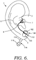
- the audio device 100 is installed in a piercing in the pinna 1 of the user's ear as depicted in FIG. 6 .
- two of the audio devices 100 are worn simultaneously, one in each ear of the user, to provide audio outputs to each ear, such as to provide stereo sound.
- the audio device 100 comprises a taper-style earring, as described previously, the audio device 100 is usually installed in a piercing in the lobe 3 of the ear.
- the control unit 116 is removed from the first end 112 of the body 110 and the body 110 inserted through the piercing.
- the audio device 100 is typically positioned with the first end 112 extending through the lobe 3 to a position between the ear and the head of the user although the reverse placement can be employed.
- the control unit 116 is recoupled to the body 110.
- a receiver 139 of a wired connection 141 can be coupled to the first end 112 of the body 110 and connected to the master device 133 as shown in FIG. 8 .
- the audio device 100 is thereby substantially captured by the interaction of the conical form of the body 110 and the enlarged dimensions of the housing 118 of the control unit 116.
- the dimensions of the second end 114 of the body 110 and of the housing 118 are preferably larger than that of the piercing into which the audio device 100 is inserted.
- the audio device 100 can be drawn at least partially through the piercing to at least partially stretch the lobe 3 and thereby provide some frictional engagement therebetween.
- the annular flange 158 on the body 110 can provide an additional obstruction to passage of the second end 114 of the body 110 through the piercing.
- the cover 152 is pivoted to the open position and the sound-production unit 136 is withdrawn from within the body 110.
- the sound-production unit 136 is extended from the body 110 and placed at least partially into a space in the pinna 1 proximate the ear canal 2 and defined by the by the antihelix 6, concha 8, and tragus 7 and directed toward the ear canal 2 of the user.
- the sound-production unit 136 may be inserted at least partially into the ear canal 2.
- the conductor 138 extends from the sound-production unit 136, into the body 110 and to the first end 112 thereof to communicatively couple with the control unit 116.
- the cover 152 can be returned to the closed position with the conductor 138 disposed in the aperture 162. As such, the audio device 100 retains an attractive ornamental appearance of an earring during use for production of audio outputs from the sound-production unit 136.
- An initial setup of the audio device 100 with the master device 133 may be carried out.
- the setup may include a series of communications between the audio device 100 and the master device 133 to complete processes, such as pairing among others known in the art for providing wireless communications between such devices.
- the user selects an audio file or track to be played by the master device 133.
- the master device 133 wirelessly (or through the wired connection 141) transmits or streams the audio file to the audio device 100 via the wireless communications unit 120.
- the wireless communications unit 120 receives the audio file for use by the control unit 116 to generate signals to the sound-production unit 136 for production of an audible output therefrom.
- the signal path of signals embodying the audio file received from the master device 133 travels from a first side of the pinna 1, through the body 110 of the audio device 100 and thus through the pinna 1, and through the conductor 138 to the space proximate the ear canal 2 or in the ear canal 2 where the audio output is finally provided.
- the user might alternatively employ the control surfaces 134 on the audio device 100 to instruct the master device 133 to begin playing a desired audio track, skip to a next or a previous track, pause, rewind, fast-forward, or stop playing an audio track.
- the user might also use the control surfaces 134 to navigate menus, interact with software applications, answer incoming telephone calls, provide voice commands, or the like.
- the sound-production unit 136 and conductor 138 are returned to the body 110 and the cover 152 moved to the closed position.
- the audio device 100 is wearable as an ornamental earring.
- the body 110, housing 118 of the control unit, and cover 152 can include any desired exterior ornamentation to enhance the appearance of the audio device 100.
- the sound-production unit 136 is completely enclosed and hidden from view.
- the audio device 200 is configured as an industrial-style earring. Industrial-style earrings are typically inserted through a pair of piercings in the helix 4 or other cartilaginous portions of the pinna 1, as shown in FIG. 10 .
- the body 210 of the audio device 200 comprises an elongate cylindrical form with first and second connectors 264, 266 disposed at the first and second ends 212, 214 thereof, respectively.
- the first connector 264 removeably couples the body 210 with the control unit 216 and the second connector 266 removeably couples the second end 214 of the body 210 with the conductor 238 in a manner similar to that described above with respect to the audio device 100 for connecting the first end 112 of the body 110 with the control unit 116.
- the first and second connectors 264, 266 are conical members having a diameter that is larger than the diameter of the body 210, but in other embodiments can have another shape and dimension. As such, when installed in the pinna 1 of the user, the first and second connectors 264, 266 may act to obstruct passage of the body 210 through the piercings. One or both of the first and second connectors 264, 266 may also be removeably coupled to the body 210 to enable removal thereof for installation of the body 210 in the pinna 1. Alternatively, the conical shape of the connectors 264, 266 may aid insertion of the connectors 264, 266 and the body 210 through the piercings by stretching of the piercings.
- the conductor 238 of the audio device 200 includes a receiver 268 at a one end thereof that couples the conductor 238 to the second connector 266 and thus, to the body 210 which forms or provides a second segment of the conductor 238 extending through or along the body 210.
- the sound-production unit 236 is coupled to the opposite end of the conductor 238 and thus is suspended from the second end 214 of the body 210 via the conductor 238.
- the second segment of the conductor 238 thus continues the path of the conductor 238 between the sound-production unit 236 and the control unit 216 or to a wired coupling with a master device (see the wired coupling 141 and the master device 133 depicted in FIG. 8 ).
- FIGS. 14A-D the second or other segments of the conductor 238 can take a variety of configurations.
- FIG. 14A depicts a positive and negative conductor 238a, 238b disposed interior to the body 210 and FIG. 14B depicts the positive and negative conductors 238a, 238b disposed in a wall of the body 210.
- FIG. 14C shows the conductors 238a, 238b disposed on an exterior surface of the body 210 and in FIG. 14D depicts sidewalls of the body 210 functioning as the conductors 238a, 238b with an insulating member 269 disposed therebetween.
- FIG. 14A depicts a positive and negative conductor 238a, 238b disposed interior to the body 210
- FIG. 14B depicts the positive and negative conductors 238a, 238b disposed in a wall of the body 210.
- FIG. 14C shows the conductors 238a, 238b disposed on an exterior surface of the body 210
- a chain 270 or other non-extensible member can be intertwined with, disposed alongside, or otherwise associated with the conductor 238.
- the chain 270 may provide additional support for the sound-production unit 236 as it is suspended and/or may be provided to enhance aesthetic qualities of the conductor 238.
- the chain 270 may be coupled to the receiver 268 and to the base 244 of the housing 242.
- a conductor 238a comprise a resilient or extensible conductor 238a that has a shape memory.
- the conductor 238a has a helical or spiral form that can be elongated by pulling or stretching the conductor 238a. When released the conductor 238a will substantially resume its previous form.
- the cover 252 comprises a pair of actuatable halves, shells, or leaves 272 that are moveable from a use position ( FIGS. 9 and 11 ) to a non-use position ( FIGS. 10 and 12 ).
- the leaves 272 are disposed alongside the base 244 of the housing 242 to expose the earbud 250 and not interfere with insertion thereof into the ear canal 2 of the user.
- the leaves 272 are shaped to generally mimic the shape of the earbud 250 and the base 244 of the housing 242. As such, the leaves 272 can lie substantially alongside and in close proximity to the sides of the base 244.
- the leaves 272 are rotated or pivoted to extend toward a distal end of the sound-production unit 236 and to substantially enclose the earbud 250 therebetween.
- the cover 252 comprises a cap that is mechanically, or magnetically coupled to the housing 242 and may be removable therefrom.
- the audio device 200 is disposed in the pinna 1 of the user's ear, as depicted in FIG. 10 .
- the leaves 272 are rotated from the non-use position to the use position to expose the earbud 250.
- the sound-production unit 236 is placed in the space proximate to the ear canal 2 and the audio device 200 is operated as described previously above with respect to the audio device 100.
- the signal path of signals embodying the audio file received from the master device 233 travels from a first side of the pinna 1 through the body 210 of the audio device 200 and thus passes through the pinna 1 two times before passing through the conductor 238 to the space proximate the ear canal 2 where the audio output is finally provided.
- the sound-production unit 236 When use of the audio device 200 for audio output is no longer desired, the sound-production unit 236 is removed from the space proximate the ear canal 2 and the leaves are returned to the non-use position. The sound-production unit 236 is then allowed to dangle or suspend from the second end of the body 210, as shown in FIG. 10 .
- the housing 242, the leaves 272, and the chain 270 may be provided with an ornamental appearance to enhance the attractiveness of the audio device 200 as an earring. If desired, one or both of the conductor 238 with the sound-production unit 236 and the control unit 216 can be removed from the body 210 and the body 210 worn alone as an earring.
- the audio device 300 is configured as a spiral-type earring.
- the spiral-type is similar to the industrial-type except for the body 310 thereof being provided in a spiraling or helical form.
- Features and operation of the audio device 300 correspond to those of the audio device 200 described previously above and are thus not described further here.
- the audio device 400 is configured as a gauge-style earring and might also be referred to as a tunnel- or plug-style earring.
- Gauge-style earrings are configured for receipt in an enlarged piercing that is often placed in the lobe 3 as shown in FIGS. 18-19 .
- the audio device 400 includes a generally ring-shaped body 410 with a hollow interior passage 473 and an annular channel 474 formed about the circumference of the body 410.
- the annular channel 474 is configured to receive the perimeter of a piercing in the lobe 3 and to thereby retain the audio device 400 within the lobe 3.
- the lobe 3 is substantially contained between opposite sides or flanges forming the annular channel 474.
- the channel 474 comprises only a slight annular recess or is not provided.
- the first end 412 of the body includes an annular wall 476 depending therefrom.
- the control unit 416 is disposed in a cap-shaped housing 418 that includes a generally planar body 478 with a flange 480 extending normally thereto and from the perimeter thereof.
- the annular wall 476 is received within the flange 480 and the housing 428 to removeably couple the control unit 416 to the body 410.
- the control unit 416 may take a form, such as that of the control units 116 and 216 that couples to a feature disposed on the first end 412 of the body 410.
- the housing 442 includes a cylindrical base 444 with a plurality of ribs 447 disposed thereon.
- An enlarged disc 482 having dimensions larger than the base 444 is provided on the base 444 opposite the earbud 450.
- the enlarged disc 482 is replaced by another ornamental feature, such as a spike, stud, hook, or chain, among a variety of others. Or the enlarged disc 482 may be omitted.
- the conductor 438 couples to the base 444 of the housing 442 proximate to the enlarged disc 482.
- a groove 484, trough, or other depression is provided about the circumference of the body 410 alongside the annular channel 474.
- the groove 484 is configured to receive the conductor 438 therein.
- the conductor 438 can be received on the exterior surface of the body 410 without the provision of a groove or other feature to retain the conductor 438.
- a cutout 486 is provided in a sidewall of the groove 484 to provide for passage of the conductor 438 from the housing 442 through the sidewall and into the groove 484. As best depicted in FIG.
- the conductor 438 can thus be disposed through the cutout 486 and into the groove 484 to wrap around the circumference of the body 410 before communicatively coupling with the control unit 416.
- the end of the conductor 438 opposite the sound-production unit 436 may insert into the body 410 and extend therein to a coupling with the control unit 416.
- the conductor 438 might alternatively insert into the body 410 to couple to a printed circuit or other electrical contact. Or the conductor 438 may be routed into the interior passage 473 and then toward the control unit 416 for coupling therewith.
- the sound-production unit 436 and the conductor 438 are disposable in a stowed position ( FIGS. 16-18 ) and a use position ( FIG. 19 ).
- the sound-production unit 436 is at least partially inserted into the interior passage 473 of the body 410 to place the nipple 446 of earbud 450 adjacent or in contact with an interior surface of the control unit 416.
- the ribs 447 may frictionally engage the wall of the interior passage 473 to retain the sound-production unit 436 in the stowed position.
- the conductor 438 is disposed and retained in the groove 484.
- the enlarged disc 482 is grasped by the user and pulled to remove the sound-production unit 436 from the interior passage 473 of the body 410.
- a small gap may be provided between the second end 414 of the body 410 and the enlarged disc 482 to aid grasping thereof.
- the conductor 438 is removed from the groove 484 and the sound-production unit 436 extended and inserted into the space proximate the ear canal 2 an directed toward or into the ear canal 2.
- the signal path of signals embodying the audio file received from the master device travels from a first side of the pinna 1, through the body 410 of the audio device 400 and thus through the pinna 1, and through the conductor 438 to the space proximate ear canal 2 where the audio output is finally provided and directed toward or into the ear canal 2.
- the audio device 400 When not in use for production of audio output, the audio device 400 is wearable as a decorative earring.
- the enlarged disc 482, as well as the body 410 and the housing 418 of the control unit 416 can be adorned with any desired ornamentation.
- the enlarged disc 482 may also obscure or hide the conductor 438 extending from the housing 442 to the groove 484.
- control unit 416 and/or the sound-production unit 436 may be detachable from the body 410 for use with a different body 410.
- a different body 410 For example, in the practice of wearing gauge-style piercings, users often slowly increase the size or gauge of the earring and thus the size of the piercing in the ear. As such, when the user wishes to increase (or decrease) the size of the body 410, a new larger body 410 is obtained and the control unit 416 and/or sound-production unit 436 are coupled to the new larger body 410. The user is thus not required to obtain an entirely new audio device 400.
- the audio device is provided with a set of interchangeable bodies 410 of varied sizes.
- the audio device 400 is configured to include a connector coupled to a sound-production unit, like the connector 266 and the sound-production unit 236 discussed previously with respect to the audio device 200.
- a connector and sound-production unit may be provided instead of or in addition to the sound-production unit 436.
- the audio device 400 could be configured with a suspended or dangling sound-production unit like that shown in FIG. 9 , for example.
- a pair of the audio devices 100, 200, 300, 400 may be employed-one in each ear-to listen to an audio output in both ears at the same time.
- the pair of audio devices can comprise two like audio devices 100, 200, 300, 400 or different devices can be selected, e.g. an audio device 100 can be used in one ear while an audio device 300 is used in the other ear.
Landscapes
- Engineering & Computer Science (AREA)
- Physics & Mathematics (AREA)
- Acoustics & Sound (AREA)
- Signal Processing (AREA)
- Health & Medical Sciences (AREA)
- Otolaryngology (AREA)
- Manufacturing & Machinery (AREA)
- Headphones And Earphones (AREA)
- Telephone Set Structure (AREA)
- Adornments (AREA)
- Circuit For Audible Band Transducer (AREA)
Description
- Piercing of various parts of the body for insertion of jewelry has been conducted by humans for thousands of years for a variety of reasons. Some piercings are completed for religious or spiritual beliefs and ceremonies while others are for ornamental purposes. The most common piercings are those in lobes of the ears, but a variety of other locations both in different parts of the ear as well as other parts of the body are not uncommon. For example, ear piercings are commonly formed in cartilaginous parts of the ear like the helix, concha, or tragus, among others.
- Common earrings include a thin stud that is inserted through the lobe of the ear and retained in place by a clutch installed thereon. However, some subcultures or piercing "purists" employ larger body jewelry that requires or forms much larger piercings in the lobe or other portions of the ear. The body jewelry worn in these piercings is often held in place without the use of a clutch or other fastener and may require insertion into a piercing by stretching the piercing to allow passage of an enlarged end of the jewelry and then allowing the piercing to shrink or return to an original size to retain the jewelry therein.
- These body jewelry pieces are available in a variety of types. One type of body jewelry that is often used in cartilaginous parts of the ears is referred to as an industrial piercing. The industrial comprises an elongate rod with enlarged ends that is typically disposed to extend through a pair of piercings in the upper portion of the ear. Another form or variation of an industrial piercing is a spiral piercing which includes a spiral shaped body that is disposed in two or more piercings in the ear and may spiral or wrap around an edge or the scapha of the ear.
- Gauge-style earrings comprise piercings in which a small initial piercing is created through, for example, the lobe of the ear. The piercing is then expanded or stretched over time by placing incrementally larger earrings therein. These earrings are referred to by their diametrical size measured using the American Wire Gauge (AWG) standard or in millimeters. Such earrings include those referred to as a taper and a gauge. A taper typically includes a body that is larger at one end than the other. An enlarged ball or similar feature may be disposed at the point thereof. The taper may be employed to slowly expand the piercing. The weight of the taper can apply a stretching force on the piercing as a result of the expanding shape of the taper as it is pulled through the piercing. Gauge-style earrings generally comprise a ring, also known as a tunnel, or a plug that is disposed within the piercing.
- Piercings and/or clamps or wraps have also been employed to support audio devices, such as hearing aids and speakers, on the ear of a user. For example,
U.S. Patent No. 8,086,288 to Klein describes a wireless earring headset that is attached to the lobe of a user's ear via a stud extending through a small piercing in the user's ear and held in place by a clutch or clasp coupled to the stud. The headset includes a speaker that is directed toward the user's ear canal and a microphone disposed on a boom directed toward the user's mouth. This configuration with the large body and the microphone boom extending therefrom may be found by users to be bulky and unattractive for wearing in public or in a social setting. -
U.S. Patent No. 7,536,150 to Ryann describes a wireless earpiece assembly configured to give the appearance of an earring. The assembly is attached to the lobe of the user's ear via a stud or clasp which fully supports the assembly. Other contact with the ear is avoided to reduce discomfort caused by long-term use. The assembly includes a coupling mechanism or hoop on which a speaker and a casing are disposed. The speaker is positioned to direct sound toward the user's ear canal and the casing is suspended from the coupling mechanism and houses operational components of the assembly. Although, the configuration described by the '150 patent is ostensibly designed to resemble an earring, the speaker is fully visible and disposed adjacent the ear of the user during wearing of the assembly. -
U.S. Patent Application Publication No. 2012/0308069 to Stott describes a gauge-style piercing with a speaker disposed therein. The speaker is directed outwardly and away from the user's ear to enable the user to hear audio outputs therefrom while also retaining the ability to hear sounds from their surroundings and environment. The '069 publication teaches that such a configuration is necessary to ensure the safety of the user and to avoid bulky or uncomfortable headphones that are placed in the user's ear canal and that block out environmental noises. However such a configuration broadcasts the audio outputs to the user's surroundings which may be unwanted by the user or by those nearby.US 5,828,757 discloses an audio device worn in a piercing in a user's ear comprising an elongate body having a first end and an opposite second end, the body is adapted to be disposed to extend through a piercing in a ear of a user, the audio device further comprising a communication component in the sound-production unit coupled to the first end of the body. The audio device is completely arranged at the outside side of the ear-lobe and fixed to the ear by post and backing member. A comparably audio device is disclosed inUS 2008/03311966 A1 - A need exists for body jewelry disposable in a piercing and with an integral audio device that can be disguised as ornamental jewelry when not used as an audio device. A need also exists for such a device that is configured for gauge and cartilaginous piercings. The invention is defined by the subject-matter of
claim 1. - Embodiments of the invention are defined by the claims below, not this summary. A high-level overview of various aspects of the invention are provided here for that reason, to provide an overview of the disclosure, and to introduce a selection of concepts that are further described in the Detailed-Description section below. This summary is not intended to identify key features or essential features of the claimed subject matter, nor is it intended to be used as an aid in isolation to determine the scope of the claimed subject matter. In brief, this disclosure describes, among other things, a device that is wearable in an ear piercing as body jewelry and that includes an integral audio device.
- The device includes a body with a wireless communications unit and a sound-production unit, such as a speaker or transducer coupled thereto. The wireless communications unit is connected to a first end of the body and transmits audio output signals through the body to the sound-production unit. The sound-production unit is coupled to the opposite second end of the body via a flexible conduit to allow the sound-production unit to be placed in proximity to or at least partially in the ear canal of the user when listening to audio output. When listening is not desired, the sound-production unit can be covered by an ornamental cover and suspended from the second end of the body or disposed within the body.
- The wireless communications unit may be detachable from the body to enable a wired connection to be made to the body. The wireless communication unit, the body, and/or the sound-production unit might also include one or more input surfaces that can be manipulated by a user to control a master device that is coupled thereto.
- Illustrative embodiments of the invention are described in detail below with reference to the attached drawing figures, and wherein:
-
FIG. 1 is a diagram depicting the pinna or outer portion of a human ear and parts thereof; -
FIG. 2 is a perspective view of an audio device configured as a taper-style earring; -
FIG. 3 is a perspective view of the audio device ofFIG. 2 depicted with a cover in an open position and a sound-production unit extending from an end of the device; -
FIG. 4 is an elevational view of the audio device ofFIG. 2 depicted with exterior walls removed to reveal components disposed therein; -
FIG. 5 is a block diagram depicting components of a control unit of an audio device; -
FIG. 6 depicts the audio device ofFIG. 2 disposed in a piercing in the lobe of an ear with an audio-production device disposed to direct audio outputs toward the ear canal; -
FIG. 7 is a diagrammatic view of wireless communications between a wireless communications unit disposed in a control unit of the audio device ofFIG. 2 and a master device; -
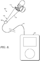
FIG. 8 is a diagrammatic view depicting a wired connection between the audio device ofFIG. 2 and a master device; -
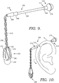
FIG. 9 is a perspective view of an audio device configured as an industrial-style earring depicted in accordance with the invention; -
FIG. 10 depicts the audio device ofFIG. 9 disposed in a pair of piercings in the helix of an ear in accordance with the invention; -
FIG. 11 is an elevational view of the audio device ofFIG. 9 depicted with exterior walls removed to reveal components disposed therein; -
FIG. 12 is a perspective view of the audio device ofFIG. 9 depicting a cover enclosing a sound-production unit; -
FIG. 13 is a perspective view of an audio device configured as an industrial-style earring with an extensible conductor configured in a helical form and coupling a body with a sound-production unit of the audio device in accordance with an embodiment of the invention; -
FIG. 14A depicts a positive and negative element of a conductor disposed interior to a body of an audio device in accordance with an embodiment of the invention; -
FIG. 14B depicts a positive and negative element of a conductor disposed within a wall of a body of an audio device in accordance with an embodiment of the invention; -
FIG. 14C depicts a positive and negative element of a conductor disposed on an exterior surface of a body of an audio device in accordance with an embodiment of the invention; -
FIG. 14D depicts sidewalls of a body of an audio device forming positive and negative element of a conductor in accordance with an embodiment of the invention; -
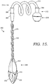
FIG. 15 is a perspective view of an audio device configured as a swirl-style earring depicted in accordance with another embodiment of the invention; -
FIG. 16 is a perspective view of an audio device configured as a gauge-style earring; -
FIG. 17 is a partial cross-sectional view of the audio device ofFIG. 16 ; -
FIG. 18 depicts the audio device ofFIG. 16 disposed in a piercing in a lobe of an ear with a sound-production unit in a stowed position -
FIG. 19 depicts the audio device ofFIG. 16 disposed in a piercing in a lobe of an ear with a sound-production unit extended from the body of the audio device and disposed in the ear canal of the user. - The subject matter of select embodiments of the invention is described with specificity herein to meet statutory requirements. But the description itself is not intended to necessarily limit the scope of claims. Rather, the claimed subject matter might be embodied in other ways to include different components, steps, or combinations thereof similar to the ones described in this document, in conjunction with other present or future technologies. Terms should not be interpreted as implying any particular order among or between various steps herein disclosed unless and except when the order of individual steps is explicitly described.
- Embodiments of the invention are described herein with respect to the drawings in which reference numerals are employed to identify particular components or features. Corresponding elements in the various embodiments depicted are provided with reference numerals having matching second and third digits but with differing first digits, e.g. element 10 corresponds to
elements - With initial reference to
FIG. 1 , an external portion orpinna 1 of a human ear is depicted. Thepinna 1 comprises a soft appendage generally comprised of cartilage and soft or fleshy tissues that collect and direct sound toward theear canal 2 for receipt by the inner ear as known in the art. A variety of portions of thepinna 1 may be pierced for insertion of body jewelry. For example, thelobe 3 comprises fleshy tissues such as skin, and may be pierced for insertion of an earring or body jewelry such as a taper- or gauge-style earring. Hereinafter, earrings and body jewelry that are insertable in a piercing in thepinna 1 are collectively referred to as earrings. Thehelix 4,scapha 5,antihelix 6,tragus 7,concha 8, andantitragus 9 are a cartilaginous portions of thepinna 1 that can be pierced for insertion of earrings known as an industrial, spiral, rook, tragus, and conch, among others. - With reference now to
FIGS. 2-8 , anaudio device 100 that is wearable in a piercing in thepinna 1 of the ear is described. Theaudio device 100 is configured as a taper-style earring and includes a
body 110 having a generally conical form. The conical form provides afirst end 112 of thebody 110 with dimensions that are smaller than those of an oppositesecond end 114. Although thebody 110 is described herein as including a linear or straight conical taper-style form, it is to be understood that thebody 110 can take a variety of different taper-style forms including for example, curved, spiral, claw, or horn shaped tapers among others. Thebody 110 includes a substantially hollow interior space and is removeably coupled at thefirst end 112 to acontrol unit 116. - The
control unit 116 includes ahousing 118 having dimensions larger than thefirst end 112 of thebody 110, e.g. thehousing 118 has a diameter that is larger than the diameter of thefirst end 112 of thebody 110, but thehousing 118 can have any desired dimensions-larger or smaller than those of thebody 110. Thehousing 118 is preferably configured in a spheroidal form but any desired form can be employed. The size and shape of thehousing 118 may aid in avoiding inadvertent withdrawal of theaudio device 100 from the piercing. Other components might also or alternatively be employed to avoid inadvertent withdrawal and/or to maintain positioning of thebody 110 in the piercing, such as rubber o-rings. - As depicted in
FIG. 5 , a variety of components are disposed in thehousing 118 and configured for operation of theaudio device 100 including awireless communications unit 120, a processor orlogic chip 122, an on-board memory 124, and abattery 128. Anamplifier 130 and amicrophone 132 might also be included, among a variety of other components. It is to be understood that one or more of these components can be combined or their functions performed by another component. For example, processors can include memory. Additionally, detail of the connections and communications between the components is not necessary for conveying an understanding of embodiments of the invention and is not described in detail herein. - The
wireless communications unit 120 employs wireless communications protocols, standards, hardware, and the like, available in the art, such as, for example, the BLUETOOTH standards developed by the Bluetooth Special Interest Group. As shown inFIG. 7 , thewireless communications unit 120 in thecontrol unit 116 provides wireless communications between theaudio device 100 and amaster device 133 such as a digital music player, a cellular telephone, a computer, or similar electronic device. Themaster device 133 provides audio data, and control signals, among other communications to theaudio device 100 via wireless communications with thewireless communications unit 120 for use by theaudio device 100. Theaudio device 100 may also transmit a variety of communications to themaster device 133 via thewireless communications unit 120 like, for example, handshake signaling for creating a secure connection therebetween, audio data collected by themicrophone 132, or command signals to themaster device 133, e.g. to change an audio file being played, among others. - The processor or
logic chip 122 executes one or more programs or routines useable to produce an audible output using audio data received from themaster device 133 via thewireless communications device 120. Theprocessor 122 may process audio inputs received from themicrophone 132 for communication to themaster device 133. Additionally, one ormore control surfaces 134 can be provided on theaudio device 100 from which theprocessor 122 can receive input commands. The control surfaces 134 can include touch interfaces, such as capacitive surfaces, buttons, switches, rotatory dials, or the like and enable a user to provide inputs to theaudio device 100 or to themaster device 133. In one embodiment, a capacitive touch interface is provided in a base or distal end of thehousing 118. In another embodiment, a lower portion of thehousing 118 is rotatable with respect to an upper portion or with respect to thebody 110 to provide input to theaudio device 100 or to the master controller. For example, a user might provide an input to change an audio track being played, to increase a volume of the audio output, or to interact with an application executing on themaster device 133. - The on-
board memory 124 is useable by theprocessor 122 for execution of programs and routines but is not configured to provide storage of audio or other data for later playback, e.g. thememory 124 cannot be used to store audio data for a plurality of songs on theaudio device 100 for later playback in a manner similar to a digital music player-such tasks are reserved for themaster device 133. In another embodiment, thememory 124 can be configured for storage of one or more data or audio files. - The
amplifier 130 is employed by theprocessor 122 to provide outputs useable by a sound-production unit 136 disposed proximate thesecond end 114 of thebody 110. The output of theamplifier 130 comprises electrical signals, which may be amplified, that are communicated to the sound-production unit 136 via an electrical wire orconductor 138 in a known manner. However, thecontrol unit 116 might also be configured to provide outputs to the sound-production unit 136 as air pressure waves carried by a hollow conduit, or as light rays carried by fiberoptic conduits. In one embodiment, thebody 110 functions as the electrical wire or conductor 138 (seeFIG. 14D ) or as the conduit for carrying the pressure waves or optical signals. - The
microphone 132 is any available microphone useable to receive audio inputs from a user including, for example, vocalizations provided during a telephone call as well as voice commands to themaster device 133 when such capabilities are present in themaster device 133.Additional microphones 132 may be provided at disparate locations on theaudio device 100 for use in collecting audio inputs from a user's surroundings or environment, such as in thebody 110 or in the sound-production unit 136. Such audio inputs are useable by theprocessor 122 or themaster device 133 for noise cancellation among other uses. - With continued reference to
FIG. 4 , thecontrol unit 116 is removeably coupled to thefirst end 112 of thebody 110. The coupling can be a threaded coupling provided by mating threads on thefirst end 112 of thebody 110 and areceptacle 140 in thehousing 118 of thecontrol unit 116. Or thebody 110 and thehousing 118 can include any of a variety of mating flanges, tabs, grooves, slots, or the like that enable snap-fit, friction-fit, magnetic fit, or other engageable couplings. The coupling places thecontrol unit 116 in communication with theconductor 138 by, for example, placing metallic contacts on thefirst end 112 of thebody 110 in contact with mating contacts disposed within thereceptacle 140 of thehousing 118. - As seen in
FIG. 8 , thefirst end 112 of thebody 110 may also be configured to receive awire 141 or other conductor for connection to themaster device 133 when thecontrol unit 116 is removed therefrom. The threads, flanges, tabs, or other features on thefirst end 112 of thebody 110 for coupling to thehousing 118 of thecontrol unit 116 as well as the contacts for coupling to theconductor 138 can be employed for coupling with areceiver 139 on an end of awire 141. Such a wired coupling might be employed when wireless communications are restricted, e.g. such as on an airplane, but use of theaudio device 100 is desired. - Now referring back to
FIG. 4 , theconductor 138 is coupled to thefirst end 112 of thebody 110 within the interior thereof and extends through the interior of thebody 110 toward thesecond end 114 and couples to the sound-production unit 136. Theconductor 138 is flexible and may be extensible to enable theconductor 138 to extend a distance from within thebody 110 sufficient to place a distal end of the sound-production unit 136 in proximity to theear canal 2 of a user wearing theaudio device 100 in thepinna 1 of the user's ear. As shown inFIG. 6 , the sound-production unit 136 is disposed in thepinna 1 in a space defined by theantihelix 6,concha 8, andtragus 7 and is directed toward or into theear canal 2. - As depicted in
FIGS. 3 and4 theconductor 138 is provided in a spiral or helical configuration to provide sufficient length to theconductor 138 while also enabling retraction of theconductor 138 into thebody 110. Theconductor 138 can alternatively be provided in any desired configuration that enables extension and retraction thereof as described herein. For example, theconductor 138 might be disposed on a coil or spool within thebody 110 that feeds out theconductor 138 when needed. Theconductor 138 may have a memory or may be coated with a resilient coating having a memory to at least partially bias theconductor 138 toward the retracted, spiraled configuration. Such may aid retraction of theconductor 138 into thebody 110 when desired. - The sound-
production unit 136 includes ahousing 142 comprising a base 144 with anipple 146 extending from a distal end thereof. The sound-production unit 136 includes a speaker, transducer, driver, or other sound production components (hereinafter referred to generally as a speaker) disposed in thehousing 142 and configured to produce an audible output. Other components, such as an amplifier, microphone, or the like might also be disposed in the sound-production unit 136. - The
base 144 of the sound-production unit 136housing 142 is configured with a frusto-conical form that is dimensioned to fit within the conical shape of thehousing 110 and to be received at least partially therein. As depicted inFIG. 4 , thebase 144 is received into the body 110 a distance sufficient to leave only a portion of thenipple 146 extending from thebody 110. A plurality ofribs 147, ridges, or other protuberances are provided along the perimeter of thebase 144. Theribs 147 may provide a friction-fit between the interior of thehousing 110 and thehousing 142 to removeably retain thehousing 142 therein as well as provide a cushion between thehousing 142 and thebody 110. Theribs 147 may also provide an air gap between thehousing 142 and thebody 110 to avoid thehousing 142 becoming stuck in thebody 110 as a result of entrapment of air within thebody 110. Theribs 147 or similar features might also be configured to provide a snap-fit, mechanical coupling, or magnetic coupling to aid retention of the sound-production unit 136 in thehousing 110. - The
conductor 138 is coupled to a proximate side of thebase 144 of thehousing 142 and to the speaker (not shown) or other components disposed therein. In an embodiment, one or more of the components of thecontrol unit 116 may be disposed in thehousing 142 and coupled to theconductor 138. - The
nipple 146 extends from the distal side of thehousing 142 and includes a central aperture through which sound produced by the speaker is directed and emitted from the sound-production unit 136. An exterior of thenipple 146 is configured to removeably engage anearbud 150. Theearbud 150 comprises a generally dome-shaped portion of a soft, pliable material that surrounds thenipple 146 but does not substantially obstruct thecentral aperture 148. Theearbud 150 provides cushioning to produce a comfortable fit for the user when the sound-production unit 136 is at least partially inserted in thepinna 1. Theearbud 150 may also provide some frictional characteristics to aid retention of the sound-production unit 136 in thepinna 1 as well as blocking of environmental noises or sounds from entering theear canal 2. Theearbud 150 can be produced in any desired form and from available materials known in the art. For example, theearbud 150 can be uniquely molded to a particular user'spinna 1, or can be formed from a compressible memory-foam or rubber materials, among others. - A
cover 152 is provided on thesecond end 114 of thebody 110. Thecover 152 is pivotally or hingedly coupled to thebody 110 to enable pivoting thereof from a closed position (FIGS. 2 ,4 , and6 ) covering and enclosing the sound-production unit 136 within thebody 110 and an open position (FIGS. 3 and7-8 ) in which the sound-production unit 136 can be removed from within thebody 110. In another embodiment, thecover 152 is removeably coupled to thebody 110 to allow thecover 152 to be detached therefrom. - The
cover 152 may include anotch 154 in an edge thereof that is configured to engage amating tab 156 or flange depending from the perimeter of thesecond end 114 of thebody 110.Annular flanges second end 114 of thebody 110 and thecover 152, respectively, on which thenotch 154 and thetab 156 can be disposed. Frictional, mechanical, and/or magnetic engagement between thenotch 154 and thetab 156 releaseably retain thecover 152 in the closed position. In another embodiment, a clasp or similar mechanical closure is provided to retain thecover 152 in the closed position. - As shown in
FIG. 6 , thenotch 154 extends a distance along the sidewall of thecover 152 to provide anaperture 162 through which theconductor 138 can be disposed when the sound-production unit 136 is extended from thebody 110 and thecover 152 is in the closed position. - With continued reference to
FIGS. 2-8 , operation of theaudio device 100 is described. Theaudio device 100 is installed in a piercing in thepinna 1 of the user's ear as depicted inFIG. 6 . In some embodiments, two of theaudio devices 100 are worn simultaneously, one in each ear of the user, to provide audio outputs to each ear, such as to provide stereo sound. When theaudio device 100 comprises a taper-style earring, as described previously, theaudio device 100 is usually installed in a piercing in thelobe 3 of the ear. Thecontrol unit 116 is removed from thefirst end 112 of thebody 110 and thebody 110 inserted through the piercing. Theaudio device 100 is typically positioned with thefirst end 112 extending through thelobe 3 to a position between the ear and the head of the user although the reverse placement can be employed. Thecontrol unit 116 is recoupled to thebody 110. Or areceiver 139 of awired connection 141 can be coupled to thefirst end 112 of thebody 110 and connected to themaster device 133 as shown inFIG. 8 . - The
audio device 100 is thereby substantially captured by the interaction of the conical form of thebody 110 and the enlarged dimensions of thehousing 118 of thecontrol unit 116. The dimensions of thesecond end 114 of thebody 110 and of thehousing 118 are preferably larger than that of the piercing into which theaudio device 100 is inserted. Theaudio device 100 can be drawn at least partially through the piercing to at least partially stretch thelobe 3 and thereby provide some frictional engagement therebetween. Theannular flange 158 on thebody 110 can provide an additional obstruction to passage of thesecond end 114 of thebody 110 through the piercing. - The
cover 152 is pivoted to the open position and the sound-production unit 136 is withdrawn from within thebody 110. The sound-production unit 136 is extended from thebody 110 and placed at least partially into a space in thepinna 1 proximate theear canal 2 and defined by the by theantihelix 6,concha 8, andtragus 7 and directed toward theear canal 2 of the user. The sound-production unit 136 may be inserted at least partially into theear canal 2. Theconductor 138 extends from the sound-production unit 136, into thebody 110 and to thefirst end 112 thereof to communicatively couple with thecontrol unit 116. Thecover 152 can be returned to the closed position with theconductor 138 disposed in theaperture 162. As such, theaudio device 100 retains an attractive ornamental appearance of an earring during use for production of audio outputs from the sound-production unit 136. - An initial setup of the
audio device 100 with themaster device 133 may be carried out. The setup may include a series of communications between theaudio device 100 and themaster device 133 to complete processes, such as pairing among others known in the art for providing wireless communications between such devices. - Using the
master device 133 the user selects an audio file or track to be played by themaster device 133. Themaster device 133 wirelessly (or through the wired connection 141) transmits or streams the audio file to theaudio device 100 via thewireless communications unit 120. Thewireless communications unit 120 receives the audio file for use by thecontrol unit 116 to generate signals to the sound-production unit 136 for production of an audible output therefrom. As such, the signal path of signals embodying the audio file received from themaster device 133 travels from a first side of thepinna 1, through thebody 110 of theaudio device 100 and thus through thepinna 1, and through theconductor 138 to the space proximate theear canal 2 or in theear canal 2 where the audio output is finally provided. - The user might alternatively employ the
control surfaces 134 on theaudio device 100 to instruct themaster device 133 to begin playing a desired audio track, skip to a next or a previous track, pause, rewind, fast-forward, or stop playing an audio track. The user might also use thecontrol surfaces 134 to navigate menus, interact with software applications, answer incoming telephone calls, provide voice commands, or the like. - When use of the
audio device 100 to provide an audio output is not desired, the sound-production unit 136 andconductor 138 are returned to thebody 110 and thecover 152 moved to the closed position. As such, theaudio device 100 is wearable as an ornamental earring. Thebody 110,housing 118 of the control unit, and cover 152 can include any desired exterior ornamentation to enhance the appearance of theaudio device 100. When not in use for audio output production, the sound-production unit 136 is completely enclosed and hidden from view. - With reference now to
FIGS. 9-12 , anaudio device 200 is described in accordance with the invention. Theaudio device 200 is configured as an industrial-style earring. Industrial-style earrings are typically inserted through a pair of piercings in thehelix 4 or other cartilaginous portions of thepinna 1, as shown inFIG. 10 . Thebody 210 of theaudio device 200 comprises an elongate cylindrical form with first andsecond connectors first connector 264 removeably couples thebody 210 with thecontrol unit 216 and thesecond connector 266 removeably couples thesecond end 214 of thebody 210 with theconductor 238 in a manner similar to that described above with respect to theaudio device 100 for connecting thefirst end 112 of thebody 110 with thecontrol unit 116. - The first and
second connectors body 210, but in other embodiments can have another shape and dimension. As such, when installed in thepinna 1 of the user, the first andsecond connectors body 210 through the piercings. One or both of the first andsecond connectors body 210 to enable removal thereof for installation of thebody 210 in thepinna 1. Alternatively, the conical shape of theconnectors connectors body 210 through the piercings by stretching of the piercings. - The
conductor 238 of theaudio device 200 includes areceiver 268 at a one end thereof that couples theconductor 238 to thesecond connector 266 and thus, to thebody 210 which forms or provides a second segment of theconductor 238 extending through or along thebody 210. The sound-production unit 236 is coupled to the opposite end of theconductor 238 and thus is suspended from thesecond end 214 of thebody 210 via theconductor 238. The second segment of theconductor 238 thus continues the path of theconductor 238 between the sound-production unit 236 and thecontrol unit 216 or to a wired coupling with a master device (see thewired coupling 141 and themaster device 133 depicted inFIG. 8 ). - As shown in
FIGS. 14A-D , the second or other segments of theconductor 238 can take a variety of configurations. For example,FIG. 14A depicts a positive andnegative conductor body 210 andFIG. 14B depicts the positive andnegative conductors body 210.FIG. 14C shows theconductors body 210 and inFIG. 14D depicts sidewalls of thebody 210 functioning as theconductors member 269 disposed therebetween. It is to be understood that such configurations can also be employed in other configurations of theaudio device 200, such as in theaudio device 100 discussed previously. - A
chain 270 or other non-extensible member can be intertwined with, disposed alongside, or otherwise associated with theconductor 238. Thechain 270 may provide additional support for the sound-production unit 236 as it is suspended and/or may be provided to enhance aesthetic qualities of theconductor 238. Thechain 270 may be coupled to thereceiver 268 and to thebase 244 of thehousing 242. - As shown in
FIG. 13 , aconductor 238a comprise a resilient orextensible conductor 238a that has a shape memory. Theconductor 238a has a helical or spiral form that can be elongated by pulling or stretching theconductor 238a. When released theconductor 238a will substantially resume its previous form. - The
cover 252 comprises a pair of actuatable halves, shells, or leaves 272 that are moveable from a use position (FIGS. 9 and11 ) to a non-use position (FIGS. 10 and12 ). In the use position, theleaves 272 are disposed alongside thebase 244 of thehousing 242 to expose theearbud 250 and not interfere with insertion thereof into theear canal 2 of the user. Theleaves 272 are shaped to generally mimic the shape of theearbud 250 and thebase 244 of thehousing 242. As such, theleaves 272 can lie substantially alongside and in close proximity to the sides of thebase 244. In the non-use position, theleaves 272 are rotated or pivoted to extend toward a distal end of the sound-production unit 236 and to substantially enclose theearbud 250 therebetween. In another embodiment, thecover 252 comprises a cap that is mechanically, or magnetically coupled to thehousing 242 and may be removable therefrom. - In use, the
audio device 200 is disposed in thepinna 1 of the user's ear, as depicted inFIG. 10 . When use of theaudio device 200 for audio output is desired, theleaves 272 are rotated from the non-use position to the use position to expose theearbud 250. The sound-production unit 236 is placed in the space proximate to theear canal 2 and theaudio device 200 is operated as described previously above with respect to theaudio device 100. As such, the signal path of signals embodying the audio file received from the master device 233 travels from a first side of thepinna 1 through thebody 210 of theaudio device 200 and thus passes through thepinna 1 two times before passing through theconductor 238 to the space proximate theear canal 2 where the audio output is finally provided. - When use of the
audio device 200 for audio output is no longer desired, the sound-production unit 236 is removed from the space proximate theear canal 2 and the leaves are returned to the non-use position. The sound-production unit 236 is then allowed to dangle or suspend from the second end of thebody 210, as shown inFIG. 10 . Thehousing 242, theleaves 272, and thechain 270 may be provided with an ornamental appearance to enhance the attractiveness of theaudio device 200 as an earring. If desired, one or both of theconductor 238 with the sound-production unit 236 and thecontrol unit 216 can be removed from thebody 210 and thebody 210 worn alone as an earring. - Referring now to
FIG. 15 , anaudio device 300 is described in accordance with an embodiment of the invention. Theaudio device 300 is configured as a spiral-type earring. The spiral-type is similar to the industrial-type except for thebody 310 thereof being provided in a spiraling or helical form. Features and operation of theaudio device 300 correspond to those of theaudio device 200 described previously above and are thus not described further here. - With reference to
FIGS. 16-19 , anaudio device 400 is described. Theaudio device 400 is configured as a gauge-style earring and might also be referred to as a tunnel- or plug-style earring. Gauge-style earrings are configured for receipt in an enlarged piercing that is often placed in thelobe 3 as shown inFIGS. 18-19 . - The
audio device 400 includes a generally ring-shapedbody 410 with a hollowinterior passage 473 and anannular channel 474 formed about the circumference of thebody 410. Theannular channel 474 is configured to receive the perimeter of a piercing in thelobe 3 and to thereby retain theaudio device 400 within thelobe 3. Thelobe 3 is substantially contained between opposite sides or flanges forming theannular channel 474. In some embodiments, thechannel 474 comprises only a slight annular recess or is not provided. - The
first end 412 of the body includes anannular wall 476 depending therefrom. Thecontrol unit 416 is disposed in a cap-shapedhousing 418 that includes a generallyplanar body 478 with aflange 480 extending normally thereto and from the perimeter thereof. Theannular wall 476 is received within theflange 480 and the housing 428 to removeably couple thecontrol unit 416 to thebody 410. It is understood that other available configurations of thehousing 418 of thecontrol unit 416 and the coupling with thebody 410 will be recognized by one of skill in the art. For example, thecontrol unit 416 may take a form, such as that of thecontrol units first end 412 of thebody 410. - The housing 442 includes a cylindrical base 444 with a plurality of
ribs 447 disposed thereon. Anenlarged disc 482 having dimensions larger than the base 444 is provided on the base 444 opposite theearbud 450. In another embodiment, theenlarged disc 482 is replaced by another ornamental feature, such as a spike, stud, hook, or chain, among a variety of others. Or theenlarged disc 482 may be omitted. - The
conductor 438 couples to the base 444 of the housing 442 proximate to theenlarged disc 482. Agroove 484, trough, or other depression is provided about the circumference of thebody 410 alongside theannular channel 474. Thegroove 484 is configured to receive theconductor 438 therein. Alternatively, theconductor 438 can be received on the exterior surface of thebody 410 without the provision of a groove or other feature to retain theconductor 438. Acutout 486 is provided in a sidewall of thegroove 484 to provide for passage of theconductor 438 from the housing 442 through the sidewall and into thegroove 484. As best depicted inFIG. 14 , theconductor 438 can thus be disposed through thecutout 486 and into thegroove 484 to wrap around the circumference of thebody 410 before communicatively coupling with thecontrol unit 416. The end of theconductor 438 opposite the sound-production unit 436 may insert into thebody 410 and extend therein to a coupling with thecontrol unit 416. Theconductor 438 might alternatively insert into thebody 410 to couple to a printed circuit or other electrical contact. Or theconductor 438 may be routed into theinterior passage 473 and then toward thecontrol unit 416 for coupling therewith. - The sound-
production unit 436 and theconductor 438 are disposable in a stowed position (FIGS. 16-18 ) and a use position (FIG. 19 ). In the stowed position, the sound-production unit 436 is at least partially inserted into theinterior passage 473 of thebody 410 to place the nipple 446 ofearbud 450 adjacent or in contact with an interior surface of thecontrol unit 416. Theribs 447 may frictionally engage the wall of theinterior passage 473 to retain the sound-production unit 436 in the stowed position. In the stowed position, theconductor 438 is disposed and retained in thegroove 484. - To move the sound-
production unit 436 to the use position as shown inFIG. 19 , theenlarged disc 482 is grasped by the user and pulled to remove the sound-production unit 436 from theinterior passage 473 of thebody 410. A small gap may be provided between thesecond end 414 of thebody 410 and theenlarged disc 482 to aid grasping thereof. Theconductor 438 is removed from thegroove 484 and the sound-production unit 436 extended and inserted into the space proximate theear canal 2 an directed toward or into theear canal 2. - Operation of the
audio device 400 corresponds with the operation of theaudio device 100 described above and is thus not described in detail here. As described previously, the signal path of signals embodying the audio file received from the master device travels from a first side of thepinna 1, through thebody 410 of theaudio device 400 and thus through thepinna 1, and through theconductor 438 to the spaceproximate ear canal 2 where the audio output is finally provided and directed toward or into theear canal 2. - When not in use for production of audio output, the
audio device 400 is wearable as a decorative earring. Theenlarged disc 482, as well as thebody 410 and thehousing 418 of thecontrol unit 416 can be adorned with any desired ornamentation. Theenlarged disc 482 may also obscure or hide theconductor 438 extending from the housing 442 to thegroove 484. - Additionally, the
control unit 416 and/or the sound-production unit 436 may be detachable from thebody 410 for use with adifferent body 410. For example, in the practice of wearing gauge-style piercings, users often slowly increase the size or gauge of the earring and thus the size of the piercing in the ear. As such, when the user wishes to increase (or decrease) the size of thebody 410, a newlarger body 410 is obtained and thecontrol unit 416 and/or sound-production unit 436 are coupled to the newlarger body 410. The user is thus not required to obtain an entirelynew audio device 400. In an embodiment, the audio device is provided with a set ofinterchangeable bodies 410 of varied sizes. - In another embodiment, the
audio device 400 is configured to include a connector coupled to a sound-production unit, like theconnector 266 and the sound-production unit 236 discussed previously with respect to theaudio device 200. Such a connector and sound-production unit may be provided instead of or in addition to the sound-production unit 436. As such, theaudio device 400 could be configured with a suspended or dangling sound-production unit like that shown inFIG. 9 , for example. - In use, a pair of the
audio devices audio devices audio device 100 can be used in one ear while anaudio device 300 is used in the other ear. - Many different arrangements of the various components depicted, as well as components not shown, are possible without departing from the scope of the claims below. Embodiments of the technology have been described with the intent to be illustrative rather than restrictive. Alternative embodiments will become apparent to readers of this disclosure after and because of reading it. Alternative means of implementing the aforementioned can be completed without departing from the scope of the claims below. Certain features and subcombinations are of utility and may be employed without reference to other features and subcombinations and are contemplated within the scope of the claims.
Claims (5)
- An audio device (200,300) adapted to be worn in a piercing in a user's ear, the audio device (200,300) comprising:an elongate body (210,310) having a first end (212, 312) and an opposite second end (214,314), the body (210,310) adapted to be disposed to extend through a piercing in an ear of a user;a control unit (116,216,316) being removeably coupled to the first end of the body (210,310) and including a control-unit housing (118,218,318), the control-unit housing (118,218,318) having dimensions larger than the first end of the body (210,310), and the control-unit housing (118,218,318) including a wireless-communications unit (120) and a battery (128) disposed therein;a sound-production unit (136,236,336) flexibly coupled to the second end (214,314,414) of the body (210,310) by a conductor (138,238,338) and communicatively coupled with the wireless-communications unit (120), at least a portion of a signal path of communications between the sound-production unit (136,236,336) and the wireless-communications unit (120) tracking the body (210,310), the sound-production unit (136,236,336) having a non-use orientation in which the sound-production unit (136,236,336) is suspended from the second end (214,314) of the body (210,310) and a use orientation in which the sound-production unit (136,236,336) is disposed at least partially within a space in the pinna (1) of the ear defined by the antihelix (6), concha (8), and tragus (7) of the ear, and the sound-production unit (136,236,336) is directed toward the ear canal (2).
- The audio device of claim 1, further comprising:
a non-extensible member disposed between the second end (214,314) of the body (210,310) and the sound-production unit (136,236,336). - The audio device of claim 1, further comprising:
a connector (266,366) disposed on a free end of the conductor (138,238,338) and removeably coupled to the second end (214,314) of the body (210,310), the connector (266,366) enabling detachment of the sound-production unit (136,236,336) and the conductor (138,238,338) from the body (210,310), the connector (266,366) having a diameter larger than a diameter of the body (210,310) and when coupled to the body (210,310) obstructing passage of the body (210,310) through the piercing in the ear of the user. - The audio device of claim 1, wherein the sound-production-unit (136,236,336) comprises a speaker disposed in a sound-production-unit housing (142,242,342),
a cover (252,352) being coupled to the sound-production-unit, housing (142,242,342), the cover (252,352) comprising a pair of actuatable halves, shells or leaves (272,372), the halves, shells or leaves (272) being movable between a non-use position in which the cover (252,352) substantially encloses the distal end of the sound-production-unit housing (142,242,342) and a use position in which the cover (152,252,352) does not interfere with insertion of the sound-production-unit housing (142,242,342) into the ear canal (2) of the user. - The audio device of claim 1, wherein the audio device (200,300) includes one or more control surfaces (134) on the control-unit housing (118,218,318,418) that are useable to control a master device (133,233), the master device (133,233) being communicatively coupled with the wireless-communications unit (120).
Applications Claiming Priority (3)
| Application Number | Priority Date | Filing Date | Title |
|---|---|---|---|
| US201261640303P | 2012-04-30 | 2012-04-30 | |
| US13/835,975 US9084054B2 (en) | 2012-04-30 | 2013-03-15 | Ear jewelry with wireless audio device |
| PCT/US2013/061423 WO2014143160A1 (en) | 2012-04-30 | 2013-09-24 | Ear jewelry with wireless audio device |
Publications (3)
| Publication Number | Publication Date |
|---|---|
| EP2974359A1 EP2974359A1 (en) | 2016-01-20 |
| EP2974359A4 EP2974359A4 (en) | 2016-11-09 |
| EP2974359B1 true EP2974359B1 (en) | 2019-07-10 |
Family
ID=49477318
Family Applications (1)
| Application Number | Title | Priority Date | Filing Date |
|---|---|---|---|
| EP13877941.8A Not-in-force EP2974359B1 (en) | 2012-04-30 | 2013-09-24 | Ear jewelry with wireless audio device |
Country Status (11)
| Country | Link |
|---|---|
| US (1) | US9084054B2 (en) |
| EP (1) | EP2974359B1 (en) |
| JP (2) | JP6151427B2 (en) |
| KR (1) | KR20150132403A (en) |
| CN (1) | CN105191341A (en) |
| AU (1) | AU2013381735B2 (en) |
| CA (1) | CA2905822A1 (en) |
| HK (1) | HK1219376A1 (en) |
| MX (1) | MX349136B (en) |
| SG (1) | SG11201507248YA (en) |
| WO (1) | WO2014143160A1 (en) |
Families Citing this family (29)
| Publication number | Priority date | Publication date | Assignee | Title |
|---|---|---|---|---|
| US9438984B1 (en) * | 2005-08-29 | 2016-09-06 | William F. Ryann | Wearable electronic pieces and organizer |
| US20140323183A1 (en) * | 2012-08-02 | 2014-10-30 | Eric Albert Klein | Hinged Miniature Wireless Headset |
| US9049515B2 (en) * | 2012-10-08 | 2015-06-02 | Keith Allen Clow | Wireless communication device |
| CN203072129U (en) * | 2013-02-02 | 2013-07-17 | 深圳市秦通科技有限公司 | Bluetooth answering device with decorative function |
| US20150110319A1 (en) * | 2013-07-29 | 2015-04-23 | Dawn Mimbs | Earring Hearing Aid |
| US9980540B2 (en) * | 2014-12-31 | 2018-05-29 | Kristy Kita | Bluetooth enabled jewelry |
| US9987169B2 (en) * | 2015-04-27 | 2018-06-05 | Otogear, Inc. | Three-dimensional attachment apparatus for hearing protection devices |
| CN104839951A (en) * | 2015-05-20 | 2015-08-19 | 杨皓翔 | Earring capable of answering telephone |
| US10051373B2 (en) * | 2015-06-01 | 2018-08-14 | Alexander Manly STAHL | Audio transducer with hybrid diaphragm |
| CN208386859U (en) | 2015-09-19 | 2019-01-15 | 佩里菲力股份有限公司 | A kind of dicoration wireless communication system and its module |
| USD800093S1 (en) | 2016-02-22 | 2017-10-17 | Shenzhen Qintong Technology Limited | Wireless headset |
| USD793369S1 (en) | 2016-02-22 | 2017-08-01 | Shenzhen Qintong Technology Limited | Wireless headset |
| USD793370S1 (en) | 2016-02-22 | 2017-08-01 | Shenzhen Qintong Technology Limited | Wireless headset |
| KR102050580B1 (en) * | 2016-06-03 | 2020-01-08 | 노바 프로덕츠 게엠베하 | Ear ornaments with headset |
| WO2018009588A1 (en) * | 2016-07-06 | 2018-01-11 | Macho Daisy Llc | Wearable device and system for personal audio messaging |
| US10735842B2 (en) | 2017-01-31 | 2020-08-04 | Teanizan, Inc. | Wireless connected jewellry device |
| CN111801950A (en) * | 2018-01-19 | 2020-10-20 | 铁三角有限公司 | Wireless Headphones |
| CN208768273U (en) * | 2018-10-02 | 2019-04-19 | 深圳市维尔晶科技有限公司 | A kind of bluetooth headset |
| US11641540B2 (en) | 2019-10-02 | 2023-05-02 | D Squared Ventures | Ear-fitting headphone attachment apparatus |
| CN111031429A (en) * | 2019-12-18 | 2020-04-17 | 怀化顺安途科技有限责任公司 | A sound external battery separation fixed wireless bluetooth ear stud earphone |
| US11197085B2 (en) * | 2019-12-20 | 2021-12-07 | Motorola Solutions, Inc. | Earpiece with an earhook and add-on eartip |
| CN111163393B (en) * | 2019-12-24 | 2021-03-23 | 东莞市融贤实业有限公司 | A topology horn and sound system |
| CN113081198B (en) | 2021-04-16 | 2025-04-15 | 曾标 | A painless slow-expansion puncture needle and use method thereof |
| US12185046B1 (en) * | 2021-06-25 | 2024-12-31 | Jay S Derman | Ear supported audio device |
| USD1032847S1 (en) | 2022-02-17 | 2024-06-25 | Aruna Pun | Earring hearing aid |
| USD1009683S1 (en) | 2022-07-08 | 2024-01-02 | Venus by Maria Tash, Inc. | Jewelry item with spike |
| USD1008841S1 (en) | 2022-07-08 | 2023-12-26 | Venus by Maria Tash, Inc. | Jewelry item with faceted spikes |
| USD1057586S1 (en) | 2022-07-12 | 2025-01-14 | Venus by Maria Tash, Inc. | Jewelry item with spikes |
| USD1057585S1 (en) | 2022-07-12 | 2025-01-14 | Venus by Maria Tash, Inc. | Jewelry item with spikes |
Citations (1)
| Publication number | Priority date | Publication date | Assignee | Title |
|---|---|---|---|---|
| CN201523441U (en) * | 2009-05-06 | 2010-07-07 | 陈瑜龙 | Earring-type bluetooth headset |
Family Cites Families (22)
| Publication number | Priority date | Publication date | Assignee | Title |
|---|---|---|---|---|
| US2506116A (en) | 1947-01-16 | 1950-05-02 | Charles H Starkey | Earring support for hearing aid tubes |
| US2909619A (en) | 1954-09-20 | 1959-10-20 | Hollingsworth Eleanor | Improved hearing-aid |
| US5533130A (en) | 1994-08-15 | 1996-07-02 | Staton; Ed | Cosmetically disguised hearing aid |
| US6493453B1 (en) | 1996-07-08 | 2002-12-10 | Douglas H. Glendon | Hearing aid apparatus |
| US5812680A (en) | 1996-07-08 | 1998-09-22 | Glendon; Douglas H. | Hearing aid apparatus |
| US5828757A (en) | 1996-12-12 | 1998-10-27 | Michalsen; Robert M. | Directional hearing aid assembly |
| US20020039427A1 (en) | 2000-10-04 | 2002-04-04 | Timothy Whitwell | Audio apparatus |
| DK174403B1 (en) | 2001-01-04 | 2003-02-10 | Gn Netcom As | Earring for headset |
| US7206429B1 (en) | 2001-05-21 | 2007-04-17 | Gateway Inc. | Audio earpiece and peripheral devices |
| JP4188804B2 (en) * | 2003-11-06 | 2008-12-03 | アルプス電気株式会社 | Earphone device |
| KR100557198B1 (en) | 2003-11-29 | 2006-03-03 | 주식회사 이어메카 | Wireless in-ear earphones |
| WO2005070070A2 (en) * | 2004-01-10 | 2005-08-04 | Chan Denise M | Ear wrap headphone or headset with ornamental object |
| US7680267B2 (en) * | 2005-07-01 | 2010-03-16 | Plantronics, Inc. | Headset with a retractable speaker portion |
| US7536150B2 (en) | 2005-08-29 | 2009-05-19 | William Frederick Ryann | Wireless earring assembly |
| US20090202096A1 (en) * | 2005-08-29 | 2009-08-13 | William Frederick Ryann | Wireless earring assembly |
| US20070058831A1 (en) | 2005-09-13 | 2007-03-15 | Jin Rie | Ear ring type two way wireless mini-ear piece |
| US20080044002A1 (en) | 2006-07-19 | 2008-02-21 | Bevirt Joeben | Wireless headset with extendable microphone |
| US8086288B2 (en) * | 2007-06-15 | 2011-12-27 | Eric Klein | Miniature wireless earring headset |
| CN201142755Y (en) | 2007-12-13 | 2008-10-29 | 上海市晋元高级中学 | Earring Headphones |
| JP4355359B1 (en) * | 2008-05-27 | 2009-10-28 | パナソニック株式会社 | Hearing aid with a microphone installed in the ear canal opening |
| US8676274B2 (en) | 2010-08-27 | 2014-03-18 | At&T Intellectual Property I, L.P. | Devices, systems, and methods for notification of events on a wireless communication device |
| US8861771B2 (en) * | 2011-06-03 | 2014-10-14 | Alan Stott | Apparatus and system for playing audio signals from an audio source |
-
2013
- 2013-03-15 US US13/835,975 patent/US9084054B2/en active Active
- 2013-09-24 SG SG11201507248YA patent/SG11201507248YA/en unknown
- 2013-09-24 CA CA2905822A patent/CA2905822A1/en active Pending
- 2013-09-24 EP EP13877941.8A patent/EP2974359B1/en not_active Not-in-force
- 2013-09-24 WO PCT/US2013/061423 patent/WO2014143160A1/en not_active Ceased
- 2013-09-24 MX MX2015012032A patent/MX349136B/en active IP Right Grant
- 2013-09-24 JP JP2016500092A patent/JP6151427B2/en not_active Expired - Fee Related
- 2013-09-24 KR KR1020157029210A patent/KR20150132403A/en not_active Withdrawn
- 2013-09-24 HK HK16107195.0A patent/HK1219376A1/en unknown
- 2013-09-24 AU AU2013381735A patent/AU2013381735B2/en not_active Ceased
- 2013-09-24 CN CN201380076356.7A patent/CN105191341A/en active Pending
-
2017
- 2017-05-24 JP JP2017102410A patent/JP2017195610A/en active Pending
Patent Citations (1)
| Publication number | Priority date | Publication date | Assignee | Title |
|---|---|---|---|---|
| CN201523441U (en) * | 2009-05-06 | 2010-07-07 | 陈瑜龙 | Earring-type bluetooth headset |
Also Published As
| Publication number | Publication date |
|---|---|
| AU2013381735A1 (en) | 2015-10-29 |
| JP2017195610A (en) | 2017-10-26 |
| MX2015012032A (en) | 2016-03-09 |
| HK1219376A1 (en) | 2017-03-31 |
| US9084054B2 (en) | 2015-07-14 |
| CN105191341A (en) | 2015-12-23 |
| KR20150132403A (en) | 2015-11-25 |
| WO2014143160A1 (en) | 2014-09-18 |
| EP2974359A1 (en) | 2016-01-20 |
| CA2905822A1 (en) | 2014-09-18 |
| US20130287241A1 (en) | 2013-10-31 |
| EP2974359A4 (en) | 2016-11-09 |
| SG11201507248YA (en) | 2015-10-29 |
| JP6151427B2 (en) | 2017-06-21 |
| JP2016512406A (en) | 2016-04-25 |
| AU2013381735B2 (en) | 2017-11-30 |
| MX349136B (en) | 2017-07-12 |
Similar Documents
| Publication | Publication Date | Title |
|---|---|---|
| US9084054B2 (en) | Ear jewelry with wireless audio device | |
| US9888309B2 (en) | Ear jewelry with wireless audio device | |
| US9942645B2 (en) | Ear jewelry with wireless audio device | |
| TWD117942S1 (en) | A dongle with wearable stereo headset | |
| WO2020191582A1 (en) | Smart watch having embedded wireless earbud, and information broadcasting method | |
| US8861771B2 (en) | Apparatus and system for playing audio signals from an audio source | |
| US9549238B2 (en) | Ear headphone with tragus fitment feature | |
| US10244298B1 (en) | Wearable wireless audio device | |
| US20140126740A1 (en) | Wireless Earpiece Device and Recording System | |
| CN203608333U (en) | Detachable headphone | |
| KR200474629Y1 (en) | Bluetooth jewelry ear cuff phone | |
| CN205847514U (en) | A kind of plastic wire earphone | |
| CN204761670U (en) | 360 half pleasant earphone of function is answered to degree language input tape | |
| JP3143713U (en) | Headphone ornaments | |
| KR101756648B1 (en) | Earphone and hearing aids for enjoyable putting on and no easy detachment on dynamic motion | |
| CN209845261U (en) | Earphone of interchangeable ear accessory | |
| CN102291642A (en) | Multifunctional ear-shaped earphone | |
| CN215769869U (en) | External equipment of wearable audio equipment | |
| KR101109020B1 (en) | Hands-free device with accessories | |
| WO2024208054A1 (en) | Earring earphone | |
| CN119255136A (en) | Earrings Headphones | |
| KR200474630Y1 (en) | Bluetooth jewelry hat band phone | |
| JP2018037753A (en) | Earphone, band member used for the same, and method of using earphone | |
| CN205847509U (en) | A kind of multifunctional earphone | |
| KR100746904B1 (en) | earphone |
Legal Events
| Date | Code | Title | Description |
|---|---|---|---|
| PUAI | Public reference made under article 153(3) epc to a published international application that has entered the european phase |
Free format text: ORIGINAL CODE: 0009012 |
|
| 17P | Request for examination filed |
Effective date: 20151009 |
|
| AK | Designated contracting states |
Kind code of ref document: A1 Designated state(s): AL AT BE BG CH CY CZ DE DK EE ES FI FR GB GR HR HU IE IS IT LI LT LU LV MC MK MT NL NO PL PT RO RS SE SI SK SM TR |
|
| AX | Request for extension of the european patent |
Extension state: BA ME |
|
| DAX | Request for extension of the european patent (deleted) | ||
| A4 | Supplementary search report drawn up and despatched |
Effective date: 20161012 |
|
| RIC1 | Information provided on ipc code assigned before grant |
Ipc: H04R 1/10 20060101AFI20161006BHEP Ipc: H04R 25/00 20060101ALI20161006BHEP |
|
| STAA | Information on the status of an ep patent application or granted ep patent |
Free format text: STATUS: EXAMINATION IS IN PROGRESS |
|
| 17Q | First examination report despatched |
Effective date: 20170627 |
|
| RAP1 | Party data changed (applicant data changed or rights of an application transferred) |
Owner name: PIEARCINGS, LLC |
|
| RIN1 | Information on inventor provided before grant (corrected) |
Inventor name: PRELOGAR, PATSY Inventor name: PRELOGAR, BARRETT |
|
| REG | Reference to a national code |
Ref country code: DE Ref legal event code: R079 Ref document number: 602013057780 Country of ref document: DE Free format text: PREVIOUS MAIN CLASS: H04R0001100000 Ipc: H04R0001020000 |
|
| GRAJ | Information related to disapproval of communication of intention to grant by the applicant or resumption of examination proceedings by the epo deleted |
Free format text: ORIGINAL CODE: EPIDOSDIGR1 |
|
| STAA | Information on the status of an ep patent application or granted ep patent |
Free format text: STATUS: GRANT OF PATENT IS INTENDED |
|
| GRAP | Despatch of communication of intention to grant a patent |
Free format text: ORIGINAL CODE: EPIDOSNIGR1 |
|
| RIC1 | Information provided on ipc code assigned before grant |
Ipc: H04R 1/10 20060101ALI20190107BHEP Ipc: H04R 1/02 20060101AFI20190107BHEP |
|
| INTG | Intention to grant announced |
Effective date: 20190124 |
|
| GRAS | Grant fee paid |
Free format text: ORIGINAL CODE: EPIDOSNIGR3 |
|
| GRAA | (expected) grant |
Free format text: ORIGINAL CODE: 0009210 |
|
| STAA | Information on the status of an ep patent application or granted ep patent |
Free format text: STATUS: THE PATENT HAS BEEN GRANTED |
|
| AK | Designated contracting states |
Kind code of ref document: B1 Designated state(s): AL AT BE BG CH CY CZ DE DK EE ES FI FR GB GR HR HU IE IS IT LI LT LU LV MC MK MT NL NO PL PT RO RS SE SI SK SM TR |
|
| REG | Reference to a national code |
Ref country code: GB Ref legal event code: FG4D |
|
| REG | Reference to a national code |
Ref country code: CH Ref legal event code: EP Ref country code: AT Ref legal event code: REF Ref document number: 1154811 Country of ref document: AT Kind code of ref document: T Effective date: 20190715 |
|
| REG | Reference to a national code |
Ref country code: IE Ref legal event code: FG4D |
|
| REG | Reference to a national code |
Ref country code: DE Ref legal event code: R096 Ref document number: 602013057780 Country of ref document: DE |
|
| REG | Reference to a national code |
Ref country code: NL Ref legal event code: MP Effective date: 20190710 |
|
| REG | Reference to a national code |
Ref country code: LT Ref legal event code: MG4D |
|
| REG | Reference to a national code |
Ref country code: AT Ref legal event code: MK05 Ref document number: 1154811 Country of ref document: AT Kind code of ref document: T Effective date: 20190710 |
|
| PG25 | Lapsed in a contracting state [announced via postgrant information from national office to epo] |
Ref country code: LT Free format text: LAPSE BECAUSE OF FAILURE TO SUBMIT A TRANSLATION OF THE DESCRIPTION OR TO PAY THE FEE WITHIN THE PRESCRIBED TIME-LIMIT Effective date: 20190710 Ref country code: PT Free format text: LAPSE BECAUSE OF FAILURE TO SUBMIT A TRANSLATION OF THE DESCRIPTION OR TO PAY THE FEE WITHIN THE PRESCRIBED TIME-LIMIT Effective date: 20191111 Ref country code: NL Free format text: LAPSE BECAUSE OF FAILURE TO SUBMIT A TRANSLATION OF THE DESCRIPTION OR TO PAY THE FEE WITHIN THE PRESCRIBED TIME-LIMIT Effective date: 20190710 Ref country code: BG Free format text: LAPSE BECAUSE OF FAILURE TO SUBMIT A TRANSLATION OF THE DESCRIPTION OR TO PAY THE FEE WITHIN THE PRESCRIBED TIME-LIMIT Effective date: 20191010 Ref country code: SE Free format text: LAPSE BECAUSE OF FAILURE TO SUBMIT A TRANSLATION OF THE DESCRIPTION OR TO PAY THE FEE WITHIN THE PRESCRIBED TIME-LIMIT Effective date: 20190710 Ref country code: AT Free format text: LAPSE BECAUSE OF FAILURE TO SUBMIT A TRANSLATION OF THE DESCRIPTION OR TO PAY THE FEE WITHIN THE PRESCRIBED TIME-LIMIT Effective date: 20190710 Ref country code: HR Free format text: LAPSE BECAUSE OF FAILURE TO SUBMIT A TRANSLATION OF THE DESCRIPTION OR TO PAY THE FEE WITHIN THE PRESCRIBED TIME-LIMIT Effective date: 20190710 Ref country code: NO Free format text: LAPSE BECAUSE OF FAILURE TO SUBMIT A TRANSLATION OF THE DESCRIPTION OR TO PAY THE FEE WITHIN THE PRESCRIBED TIME-LIMIT Effective date: 20191010 Ref country code: FI Free format text: LAPSE BECAUSE OF FAILURE TO SUBMIT A TRANSLATION OF THE DESCRIPTION OR TO PAY THE FEE WITHIN THE PRESCRIBED TIME-LIMIT Effective date: 20190710 |
|
| PG25 | Lapsed in a contracting state [announced via postgrant information from national office to epo] |
Ref country code: RS Free format text: LAPSE BECAUSE OF FAILURE TO SUBMIT A TRANSLATION OF THE DESCRIPTION OR TO PAY THE FEE WITHIN THE PRESCRIBED TIME-LIMIT Effective date: 20190710 Ref country code: IS Free format text: LAPSE BECAUSE OF FAILURE TO SUBMIT A TRANSLATION OF THE DESCRIPTION OR TO PAY THE FEE WITHIN THE PRESCRIBED TIME-LIMIT Effective date: 20191110 Ref country code: GR Free format text: LAPSE BECAUSE OF FAILURE TO SUBMIT A TRANSLATION OF THE DESCRIPTION OR TO PAY THE FEE WITHIN THE PRESCRIBED TIME-LIMIT Effective date: 20191011 Ref country code: LV Free format text: LAPSE BECAUSE OF FAILURE TO SUBMIT A TRANSLATION OF THE DESCRIPTION OR TO PAY THE FEE WITHIN THE PRESCRIBED TIME-LIMIT Effective date: 20190710 Ref country code: AL Free format text: LAPSE BECAUSE OF FAILURE TO SUBMIT A TRANSLATION OF THE DESCRIPTION OR TO PAY THE FEE WITHIN THE PRESCRIBED TIME-LIMIT Effective date: 20190710 Ref country code: ES Free format text: LAPSE BECAUSE OF FAILURE TO SUBMIT A TRANSLATION OF THE DESCRIPTION OR TO PAY THE FEE WITHIN THE PRESCRIBED TIME-LIMIT Effective date: 20190710 |
|
| PG25 | Lapsed in a contracting state [announced via postgrant information from national office to epo] |
Ref country code: TR Free format text: LAPSE BECAUSE OF FAILURE TO SUBMIT A TRANSLATION OF THE DESCRIPTION OR TO PAY THE FEE WITHIN THE PRESCRIBED TIME-LIMIT Effective date: 20190710 |
|
| PG25 | Lapsed in a contracting state [announced via postgrant information from national office to epo] |
Ref country code: RO Free format text: LAPSE BECAUSE OF FAILURE TO SUBMIT A TRANSLATION OF THE DESCRIPTION OR TO PAY THE FEE WITHIN THE PRESCRIBED TIME-LIMIT Effective date: 20190710 Ref country code: EE Free format text: LAPSE BECAUSE OF FAILURE TO SUBMIT A TRANSLATION OF THE DESCRIPTION OR TO PAY THE FEE WITHIN THE PRESCRIBED TIME-LIMIT Effective date: 20190710 Ref country code: IT Free format text: LAPSE BECAUSE OF FAILURE TO SUBMIT A TRANSLATION OF THE DESCRIPTION OR TO PAY THE FEE WITHIN THE PRESCRIBED TIME-LIMIT Effective date: 20190710 Ref country code: DK Free format text: LAPSE BECAUSE OF FAILURE TO SUBMIT A TRANSLATION OF THE DESCRIPTION OR TO PAY THE FEE WITHIN THE PRESCRIBED TIME-LIMIT Effective date: 20190710 Ref country code: PL Free format text: LAPSE BECAUSE OF FAILURE TO SUBMIT A TRANSLATION OF THE DESCRIPTION OR TO PAY THE FEE WITHIN THE PRESCRIBED TIME-LIMIT Effective date: 20190710 |
|
| PG25 | Lapsed in a contracting state [announced via postgrant information from national office to epo] |
Ref country code: SK Free format text: LAPSE BECAUSE OF FAILURE TO SUBMIT A TRANSLATION OF THE DESCRIPTION OR TO PAY THE FEE WITHIN THE PRESCRIBED TIME-LIMIT Effective date: 20190710 Ref country code: CZ Free format text: LAPSE BECAUSE OF FAILURE TO SUBMIT A TRANSLATION OF THE DESCRIPTION OR TO PAY THE FEE WITHIN THE PRESCRIBED TIME-LIMIT Effective date: 20190710 Ref country code: MC Free format text: LAPSE BECAUSE OF FAILURE TO SUBMIT A TRANSLATION OF THE DESCRIPTION OR TO PAY THE FEE WITHIN THE PRESCRIBED TIME-LIMIT Effective date: 20190710 Ref country code: IS Free format text: LAPSE BECAUSE OF FAILURE TO SUBMIT A TRANSLATION OF THE DESCRIPTION OR TO PAY THE FEE WITHIN THE PRESCRIBED TIME-LIMIT Effective date: 20200224 Ref country code: SM Free format text: LAPSE BECAUSE OF FAILURE TO SUBMIT A TRANSLATION OF THE DESCRIPTION OR TO PAY THE FEE WITHIN THE PRESCRIBED TIME-LIMIT Effective date: 20190710 |
|
| REG | Reference to a national code |
Ref country code: CH Ref legal event code: PL |
|
| REG | Reference to a national code |
Ref country code: DE Ref legal event code: R097 Ref document number: 602013057780 Country of ref document: DE |
|
| PLBE | No opposition filed within time limit |
Free format text: ORIGINAL CODE: 0009261 |
|
| STAA | Information on the status of an ep patent application or granted ep patent |
Free format text: STATUS: NO OPPOSITION FILED WITHIN TIME LIMIT |
|
| PG2D | Information on lapse in contracting state deleted |
Ref country code: IS |
|
| PG25 | Lapsed in a contracting state [announced via postgrant information from national office to epo] |
Ref country code: CH Free format text: LAPSE BECAUSE OF NON-PAYMENT OF DUE FEES Effective date: 20190930 Ref country code: IE Free format text: LAPSE BECAUSE OF NON-PAYMENT OF DUE FEES Effective date: 20190924 Ref country code: LI Free format text: LAPSE BECAUSE OF NON-PAYMENT OF DUE FEES Effective date: 20190930 Ref country code: LU Free format text: LAPSE BECAUSE OF NON-PAYMENT OF DUE FEES Effective date: 20190924 |
|
| 26N | No opposition filed |
Effective date: 20200603 |
|
| REG | Reference to a national code |
Ref country code: BE Ref legal event code: MM Effective date: 20190930 |
|
| PG25 | Lapsed in a contracting state [announced via postgrant information from national office to epo] |
Ref country code: BE Free format text: LAPSE BECAUSE OF NON-PAYMENT OF DUE FEES Effective date: 20190930 Ref country code: SI Free format text: LAPSE BECAUSE OF FAILURE TO SUBMIT A TRANSLATION OF THE DESCRIPTION OR TO PAY THE FEE WITHIN THE PRESCRIBED TIME-LIMIT Effective date: 20190710 |
|
| PG25 | Lapsed in a contracting state [announced via postgrant information from national office to epo] |
Ref country code: CY Free format text: LAPSE BECAUSE OF FAILURE TO SUBMIT A TRANSLATION OF THE DESCRIPTION OR TO PAY THE FEE WITHIN THE PRESCRIBED TIME-LIMIT Effective date: 20190710 |
|
| PG25 | Lapsed in a contracting state [announced via postgrant information from national office to epo] |
Ref country code: HU Free format text: LAPSE BECAUSE OF FAILURE TO SUBMIT A TRANSLATION OF THE DESCRIPTION OR TO PAY THE FEE WITHIN THE PRESCRIBED TIME-LIMIT; INVALID AB INITIO Effective date: 20130924 Ref country code: MT Free format text: LAPSE BECAUSE OF FAILURE TO SUBMIT A TRANSLATION OF THE DESCRIPTION OR TO PAY THE FEE WITHIN THE PRESCRIBED TIME-LIMIT Effective date: 20190710 |
|
| PG25 | Lapsed in a contracting state [announced via postgrant information from national office to epo] |
Ref country code: MK Free format text: LAPSE BECAUSE OF FAILURE TO SUBMIT A TRANSLATION OF THE DESCRIPTION OR TO PAY THE FEE WITHIN THE PRESCRIBED TIME-LIMIT Effective date: 20190710 |
|
| PGFP | Annual fee paid to national office [announced via postgrant information from national office to epo] |
Ref country code: GB Payment date: 20220927 Year of fee payment: 10 |
|
| PGFP | Annual fee paid to national office [announced via postgrant information from national office to epo] |
Ref country code: FR Payment date: 20220921 Year of fee payment: 10 |
|
| PGFP | Annual fee paid to national office [announced via postgrant information from national office to epo] |
Ref country code: DE Payment date: 20221006 Year of fee payment: 10 |
|
| REG | Reference to a national code |
Ref country code: DE Ref legal event code: R119 Ref document number: 602013057780 Country of ref document: DE |
|
| GBPC | Gb: european patent ceased through non-payment of renewal fee |
Effective date: 20230924 |
|
| PG25 | Lapsed in a contracting state [announced via postgrant information from national office to epo] |
Ref country code: GB Free format text: LAPSE BECAUSE OF NON-PAYMENT OF DUE FEES Effective date: 20230924 |
|
| PG25 | Lapsed in a contracting state [announced via postgrant information from national office to epo] |
Ref country code: GB Free format text: LAPSE BECAUSE OF NON-PAYMENT OF DUE FEES Effective date: 20230924 Ref country code: FR Free format text: LAPSE BECAUSE OF NON-PAYMENT OF DUE FEES Effective date: 20230930 Ref country code: DE Free format text: LAPSE BECAUSE OF NON-PAYMENT OF DUE FEES Effective date: 20240403 |