EP2974308B1 - Transparent display - Google Patents
Transparent display Download PDFInfo
- Publication number
- EP2974308B1 EP2974308B1 EP14713917.4A EP14713917A EP2974308B1 EP 2974308 B1 EP2974308 B1 EP 2974308B1 EP 14713917 A EP14713917 A EP 14713917A EP 2974308 B1 EP2974308 B1 EP 2974308B1
- Authority
- EP
- European Patent Office
- Prior art keywords
- display
- light
- pixels
- polarization
- emit light
- Prior art date
- Legal status (The legal status is an assumption and is not a legal conclusion. Google has not performed a legal analysis and makes no representation as to the accuracy of the status listed.)
- Active
Links
- 230000010287 polarization Effects 0.000 claims description 54
- 230000004888 barrier function Effects 0.000 claims description 21
- 230000000903 blocking effect Effects 0.000 claims description 2
- 230000002452 interceptive effect Effects 0.000 description 4
- 239000000463 material Substances 0.000 description 3
- 230000003287 optical effect Effects 0.000 description 3
- 125000006850 spacer group Chemical group 0.000 description 3
- XLYOFNOQVPJJNP-UHFFFAOYSA-N water Substances O XLYOFNOQVPJJNP-UHFFFAOYSA-N 0.000 description 3
- 230000008901 benefit Effects 0.000 description 2
- 230000005684 electric field Effects 0.000 description 2
- 230000004313 glare Effects 0.000 description 2
- 239000006096 absorbing agent Substances 0.000 description 1
- 238000013459 approach Methods 0.000 description 1
- 230000005540 biological transmission Effects 0.000 description 1
- 238000010276 construction Methods 0.000 description 1
- 230000001419 dependent effect Effects 0.000 description 1
- 238000004519 manufacturing process Methods 0.000 description 1
- 229920000642 polymer Polymers 0.000 description 1
- 230000005855 radiation Effects 0.000 description 1
- 238000000926 separation method Methods 0.000 description 1
- 239000007787 solid Substances 0.000 description 1
- 238000006467 substitution reaction Methods 0.000 description 1
- 238000002834 transmittance Methods 0.000 description 1
Images


Classifications
-
- G—PHYSICS
- G02—OPTICS
- G02B—OPTICAL ELEMENTS, SYSTEMS OR APPARATUS
- G02B30/00—Optical systems or apparatus for producing three-dimensional [3D] effects, e.g. stereoscopic images
- G02B30/20—Optical systems or apparatus for producing three-dimensional [3D] effects, e.g. stereoscopic images by providing first and second parallax images to an observer's left and right eyes
- G02B30/26—Optical systems or apparatus for producing three-dimensional [3D] effects, e.g. stereoscopic images by providing first and second parallax images to an observer's left and right eyes of the autostereoscopic type
- G02B30/30—Optical systems or apparatus for producing three-dimensional [3D] effects, e.g. stereoscopic images by providing first and second parallax images to an observer's left and right eyes of the autostereoscopic type involving parallax barriers
-
- G—PHYSICS
- G02—OPTICS
- G02B—OPTICAL ELEMENTS, SYSTEMS OR APPARATUS
- G02B30/00—Optical systems or apparatus for producing three-dimensional [3D] effects, e.g. stereoscopic images
- G02B30/20—Optical systems or apparatus for producing three-dimensional [3D] effects, e.g. stereoscopic images by providing first and second parallax images to an observer's left and right eyes
- G02B30/22—Optical systems or apparatus for producing three-dimensional [3D] effects, e.g. stereoscopic images by providing first and second parallax images to an observer's left and right eyes of the stereoscopic type
- G02B30/25—Optical systems or apparatus for producing three-dimensional [3D] effects, e.g. stereoscopic images by providing first and second parallax images to an observer's left and right eyes of the stereoscopic type using polarisation techniques
-
- G—PHYSICS
- G02—OPTICS
- G02B—OPTICAL ELEMENTS, SYSTEMS OR APPARATUS
- G02B30/00—Optical systems or apparatus for producing three-dimensional [3D] effects, e.g. stereoscopic images
- G02B30/20—Optical systems or apparatus for producing three-dimensional [3D] effects, e.g. stereoscopic images by providing first and second parallax images to an observer's left and right eyes
- G02B30/26—Optical systems or apparatus for producing three-dimensional [3D] effects, e.g. stereoscopic images by providing first and second parallax images to an observer's left and right eyes of the autostereoscopic type
- G02B30/27—Optical systems or apparatus for producing three-dimensional [3D] effects, e.g. stereoscopic images by providing first and second parallax images to an observer's left and right eyes of the autostereoscopic type involving lenticular arrays
-
- G—PHYSICS
- G02—OPTICS
- G02B—OPTICAL ELEMENTS, SYSTEMS OR APPARATUS
- G02B5/00—Optical elements other than lenses
- G02B5/30—Polarising elements
- G02B5/3025—Polarisers, i.e. arrangements capable of producing a definite output polarisation state from an unpolarised input state
- G02B5/3058—Polarisers, i.e. arrangements capable of producing a definite output polarisation state from an unpolarised input state comprising electrically conductive elements, e.g. wire grids, conductive particles
-
- G—PHYSICS
- G02—OPTICS
- G02B—OPTICAL ELEMENTS, SYSTEMS OR APPARATUS
- G02B5/00—Optical elements other than lenses
- G02B5/30—Polarising elements
- G02B5/3083—Birefringent or phase retarding elements
-
- H—ELECTRICITY
- H04—ELECTRIC COMMUNICATION TECHNIQUE
- H04N—PICTORIAL COMMUNICATION, e.g. TELEVISION
- H04N13/00—Stereoscopic video systems; Multi-view video systems; Details thereof
- H04N13/30—Image reproducers
- H04N13/302—Image reproducers for viewing without the aid of special glasses, i.e. using autostereoscopic displays
- H04N13/305—Image reproducers for viewing without the aid of special glasses, i.e. using autostereoscopic displays using lenticular lenses, e.g. arrangements of cylindrical lenses
-
- H—ELECTRICITY
- H04—ELECTRIC COMMUNICATION TECHNIQUE
- H04N—PICTORIAL COMMUNICATION, e.g. TELEVISION
- H04N13/00—Stereoscopic video systems; Multi-view video systems; Details thereof
- H04N13/30—Image reproducers
- H04N13/356—Image reproducers having separate monoscopic and stereoscopic modes
-
- H—ELECTRICITY
- H04—ELECTRIC COMMUNICATION TECHNIQUE
- H04N—PICTORIAL COMMUNICATION, e.g. TELEVISION
- H04N13/00—Stereoscopic video systems; Multi-view video systems; Details thereof
- H04N13/30—Image reproducers
- H04N13/361—Reproducing mixed stereoscopic images; Reproducing mixed monoscopic and stereoscopic images, e.g. a stereoscopic image overlay window on a monoscopic image background
-
- H—ELECTRICITY
- H10—SEMICONDUCTOR DEVICES; ELECTRIC SOLID-STATE DEVICES NOT OTHERWISE PROVIDED FOR
- H10K—ORGANIC ELECTRIC SOLID-STATE DEVICES
- H10K50/00—Organic light-emitting devices
- H10K50/80—Constructional details
- H10K50/85—Arrangements for extracting light from the devices
- H10K50/858—Arrangements for extracting light from the devices comprising refractive means, e.g. lenses
-
- H—ELECTRICITY
- H10—SEMICONDUCTOR DEVICES; ELECTRIC SOLID-STATE DEVICES NOT OTHERWISE PROVIDED FOR
- H10K—ORGANIC ELECTRIC SOLID-STATE DEVICES
- H10K50/00—Organic light-emitting devices
- H10K50/80—Constructional details
- H10K50/86—Arrangements for improving contrast, e.g. preventing reflection of ambient light
-
- H—ELECTRICITY
- H10—SEMICONDUCTOR DEVICES; ELECTRIC SOLID-STATE DEVICES NOT OTHERWISE PROVIDED FOR
- H10K—ORGANIC ELECTRIC SOLID-STATE DEVICES
- H10K59/00—Integrated devices, or assemblies of multiple devices, comprising at least one organic light-emitting element covered by group H10K50/00
- H10K59/10—OLED displays
- H10K59/12—Active-matrix OLED [AMOLED] displays
- H10K59/121—Active-matrix OLED [AMOLED] displays characterised by the geometry or disposition of pixel elements
-
- H—ELECTRICITY
- H10—SEMICONDUCTOR DEVICES; ELECTRIC SOLID-STATE DEVICES NOT OTHERWISE PROVIDED FOR
- H10K—ORGANIC ELECTRIC SOLID-STATE DEVICES
- H10K59/00—Integrated devices, or assemblies of multiple devices, comprising at least one organic light-emitting element covered by group H10K50/00
- H10K59/60—OLEDs integrated with inorganic light-sensitive elements, e.g. with inorganic solar cells or inorganic photodiodes
- H10K59/65—OLEDs integrated with inorganic image sensors
-
- H—ELECTRICITY
- H10—SEMICONDUCTOR DEVICES; ELECTRIC SOLID-STATE DEVICES NOT OTHERWISE PROVIDED FOR
- H10K—ORGANIC ELECTRIC SOLID-STATE DEVICES
- H10K59/00—Integrated devices, or assemblies of multiple devices, comprising at least one organic light-emitting element covered by group H10K50/00
- H10K59/80—Constructional details
- H10K59/875—Arrangements for extracting light from the devices
- H10K59/879—Arrangements for extracting light from the devices comprising refractive means, e.g. lenses
-
- H—ELECTRICITY
- H10—SEMICONDUCTOR DEVICES; ELECTRIC SOLID-STATE DEVICES NOT OTHERWISE PROVIDED FOR
- H10K—ORGANIC ELECTRIC SOLID-STATE DEVICES
- H10K59/00—Integrated devices, or assemblies of multiple devices, comprising at least one organic light-emitting element covered by group H10K50/00
- H10K59/80—Constructional details
- H10K59/8791—Arrangements for improving contrast, e.g. preventing reflection of ambient light
-
- H—ELECTRICITY
- H10—SEMICONDUCTOR DEVICES; ELECTRIC SOLID-STATE DEVICES NOT OTHERWISE PROVIDED FOR
- H10K—ORGANIC ELECTRIC SOLID-STATE DEVICES
- H10K2102/00—Constructional details relating to the organic devices covered by this subclass
- H10K2102/301—Details of OLEDs
- H10K2102/302—Details of OLEDs of OLED structures
- H10K2102/3023—Direction of light emission
- H10K2102/3031—Two-side emission, e.g. transparent OLEDs [TOLED]
Definitions
- This invention relates to transparent displays, and in a preferred set of examples to transparent autostereoscopic displays.
- Transparent displays enable a background behind the display to be viewed as well as the display output.
- the display thus has a certain level of transmittance.
- Transparent displays have many possible applications such as windows for buildings or automobiles and show windows for shopping malls. In addition to these large device applications, small devices such as hand held tablets may also benefit from transparent displays, for example to enable a user to view a map as well the scenery ahead though the screen.
- Transparent displays are not yet available with 3D viewing capability, and in particular not yet using glasses-free autostereoscopic approaches, such as with lenticular lenses.
- a transparent display typically has a display mode when the viewer is intended to view the display content, and a window mode when display is off and the viewer is intended to be able to see-through the display.
- a conventional combination of a lenticular lens on top of a display causes a problem if the display is transparent as the lenticular lens will cause a distorted view of the image behind the display.
- the window mode does not provide a proper view of the scene behind the window.
- the optical performance of a transparent display can also be reduced by excessive light transmitted through the display whereby the contrast is poor.
- a display comprising a display panel, wherein the display panel has an array of light emitting display pixels occupying pixel areas with a light transmissive area between the pixel areas; and a polarizer associated only with the light transmissive area.
- This arrangement provides a polarizer between the pixels, in the area which provides the transparency of the display. In the most basic implementation, this can be used to improve the contrast ratio of the display, and/or reduce glare for a transmissive function.
- the pixels can be arranged to emit light in only one of the two opposite directions normal to the display panel. In this way, one side of the display provides a display output function (in combination with a see-through function) and the other side provides only the see-through function.
- the pixels can be arranged to emit light in both opposite directions normal to the display panel, so that a display function can be provided on both sides of the panel. If the same set of pixels is used to emit light in both directions, then one viewed image will be a mirrored version of the other.
- the pixels can comprise a first set arranged to emit light in only one of the two directions normal to the display panel and a second set arranged to emit light in the opposite direction normal to the display panel. In this way, different images can be provided in the two opposite directions.
- the polarizer preferably comprises an in-plane polarizer between the pixels, and it can for example comprise a wire grid polarizer.
- the invention is of particular interest for an autostereoscopic display.
- the light emitting display pixels are then arranged to provide light of a first polarization which is orthogonal to a second polarization passed by the polarizer.
- An image forming arrangement is then provided for directing images from different sets of pixels in different lateral viewing directions thereby enabling autostereoscopic viewing, wherein the image forming arrangement is provided over one or both sides of the display.
- the display pixels can each comprise a polarizer to block light of the second polarization.
- the pixel emitters can produce non-polarized light, which is then converted by the polarizer.
- the pixels can also have a reflector or absorber to block light being emitted in the unwanted one of the two normal directions.
- One of the polarizations can be linear horizontal polarization and the other can be linear vertical polarization, or else one of the polarizations can be clockwise circular polarization and the other can be counter-clockwise circular polarization.
- a first set of examples of 3D display uses a lenticular arrangement to provide the view forming function.
- the image forming arrangement comprises a birefringent lens structure which provides a lensing function for light of the first polarization and a pass through function for light of the second polarization.
- the birefringent lens structure can be:
- This provides various possibilities, including a 3D display output on one side of the display or on both sides of the display, or a hybrid 3D display on one side and 2D display on the other side.
- a second set of examples of 3D display uses a barrier arrangement to provide the autostereoscopic view forming function.
- the image forming arrangement comprises a barrier arrangement, comprising polarizing light barriers which provide a blocking function for light of the first polarization and a pass through function for light of the second polarization.
- barrier arrangement can be:
- the invention provides a display having an array of light emitting display pixels occupying pixel areas, and a polarizing light transmissive area between the pixel areas.
- the display panel can be used as the basis of a transparent autostereoscopic 3D display using parallax barriers or lenticular lenses to generate multiple views and the polariser prevents the barriers or lenses from causing an undesired distortion of light transmitted through the display.
- the panel can be used as the basis of a transparent 2D display whereby the polariser will create superior optical performance for example by reducing the transmission of polarised reflection from water or other surfaces.
- the display enables an observer to properly see both 3D-content from the display and an undistorted view of the scenery behind the display, as well as a 2D view with improved contrast.
- the invention makes use of a transparent emissive display panel, for example with OLED pixels or transparent OLED pixels.
- a transparent emissive display panel for example with OLED pixels or transparent OLED pixels.
- At least a substantial portion of the area between the emissive elements comprises a polariser, preferably a wire grid polariser.
- a wire grid polarizer is the simplest linear polarizer in concept, and consists of a regular array of fine parallel metallic wires, placed in a plane perpendicular to the incident beam. Electromagnetic waves which have a component of their electric fields aligned parallel to the wires induce the movement of electrons along the length of the wires and the wave is essentially reflected backwards along the incident beam.
- the electrons cannot move very far across the width of each wire; therefore, little energy is reflected, and the incident wave is able to pass through the grid.
- the separation distance between the wires must be less than the wavelength of the radiation, and the wire width should be a small fraction of this distance.
- the pixel emitters When used in the 3D implementation, the pixel emitters generate light of the orthogonal polarization to that passed by the polariser between the pixels.
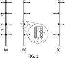
- Figure 1 shows the basic features of the transparent emissive display panel used in the various examples of display device of the invention.
- the display panel comprises a plurality of emissive pixels 1, preferably OLED pixels, with light emission in either both directions as shown in Figure 1(a) , one direction as shown in Figure 1(b) or alternating between the two directions as shown in Figure 1(c) .
- the directionality of the emission, as shown in Figures 1(b) and 1(c) can be imposed by adding a reflector behind the pixel emitter.
- the pixels may be transparent OLED pixels, top emitting OLED pixels, or alternatively bottom emitting OLED pixels as are used in standard OLED display manufacturing at present.
- the aperture ratio of the pixels is deliberately chosen to be considerably smaller than in a regular non-transparent display, typically less than 50 % aperture.
- a polariser This may for example be formed as a patterned polymer based polariser or, more preferably, a wire grid polariser 2.
- the polariser may be configured as a linear (in which case a wire grid polarizer can be used) or as a circular or elliptical polariser.
- Figure 1(b) shows in enlarged form the structure of a pixel which provides directional light emission.
- the pixel comprises a polarizer 3 (which is optional and depends on the display design) on the light output face of the pixel, the light emitting layer 5 and a reflector 6 at the back of the pixel stack.
- the emission direction is shown as arrow 4.
- a first embodiment provides a single sided 2D transparent emissive display with in-plane polariser, and is based on the panel shown in Figure 1(b) .
- the role of the polariser is to improve the contrast ratio of the display for a viewer on the right hand side of the display in the case that the light incident on the left hand side of the display to be transmitted by the display is polarised.
- This is the configuration shown in Figure 1(b) .
- a well-known cause of such polarisation is reflection of light by water, snow, ice or other reflective surfaces.
- the display should preferably have a vertical polariser.
- a second example provides a double sided 2D transparent emissive display with in-plane polariser, based on the panel shown in Figure 1(a) or Figure 1(c) .
- This display may be viewed from either one side, the other side or both sides simultaneously, depending upon which pixels are driven.
- the panel of Figure 1(a) can be viewed from both sides, but on one side the image will be mirrored.
- the image seen from either side can be driven independently at half of the resolution that is available in the panel from Figure 1(a) .
- the role of the polariser is again to improve the contrast ratio of the display for a viewer on the right hand side of the display in the case that the light incident on the left hand side of the display to be transmitted by the display is polarised. This also works for a viewer on the left hand side of the display.
- a third example provides a transparent double-sided autostereoscopic 3D display with-in-plane polariser.
- the pixel layout is based on that shown in Figure 1(c) , and with the same pixel structure as shown in Figure 1(b) including the optional polarizer 3.
- the display layer is covered on both sides with a lenticular lens arrangement comprising lenticular lenses 10 and replica layers 12. These define a lens surface at their interface.
- a parallax barrier could be used instead of the lenticular lens arrangement, and an example is given below.
- observers standing on the left and right can see both 3D content generated by the display and the scenery through the display undisturbed.
- a typical application could be an interactive shop window, a public information display, an interactive advertisement display, or a transparent computer screen.
- light transmitted through the display should not be refracted by the lenticular lens (or blocked by the parallax barrier), while light emitted by the display should be refracted by the lenticular lens (or partially blocked by the parallax barrier) in order to be able to act as an autostereoscopic 3D display.
- the lenticular lens 10 is made from a birefringent material (or the parallax barrier is made of polarizers).
- the lens or the barrier only affects one polarization state of the light, which will be named state A.
- the polarization state perpendicular to state A, which will be named state B, can propagate undisturbed through the lens or the barrier.
- the light that will be transmitted through the display is polarized with an in-plane polarizer that transmits the polarization state B.
- the light generated by the display should be of polarization state A.
- the pixels of the display should not completely block the transmitted light of polarization state B, and this is ensured by providing a suitable aspect ratio, such that light of polarization state B is transmitted in the spaces between the pixels.
- the display enables undistorted viewing through the display as well as autostereoscopic display viewing. This is made possible without needing any switchable polarising elements.
- the display only transmits one polarization state, it will be understood that typically half of the ambient light is blocked thereby reducing the brightness when looking through the display.
- the polarization state A is used to generate 3D-content and the orthogonal polarization state B is used to transmit any light undisturbed through the display.
- Two possible examples of these polarization states are:
- the material of the lens 10 has a different refractive index to the replica 12 and therefore acts as a lens for this polarization.
- the refractive index of the replica 12 should be equal to one of the refractive indices of the birefringent material of the lenticular 10. In this way, the combination of the lens and replica will act as a lenticular lens for one polarization state and as a normal spacer layer for the other polarization state.
- the polarizer 3 on top of the pixels ensures that the emitted light has the required polarization.
- Figure 3 shows a further example for a transparent single-sided autostereoscopic 3D display with in-plane polariser
- This example uses the panel design of Figure 1(b) with a lenticular lens structure (as in Figure 2 ) over one side only of the display.
- Figure 4 shows a further example for a transparent hybrid 2D autostereoscopic 3D display with in-plane polariser.
- This example uses the panel design of Figure 1(c) and has a lens arrangement on one side of the display only to realise a single-sided transparent 3D autostereoscopic display.
- the other side of the display implements a 2D display such that a hybrid 2D/3D transparent display is realised.
- the autostereoscopic examples above can be implemented with parallax barriers instead of lenticular lenses.
- an ordinary parallax barrier would cause a disturbed view of the image transmitted through the display.
- the barriers are instead made of polarisers.
- the state of the polariser is chosen to be equal to the state of the in-plane polariser 2 of the display panel, so that light transmitted through the display can travel undisturbed to an observer, while for the content created by the pixels the observer sees them through a parallax barrier.
- Figure 5 shows one example based on the double sided arrangement of Figure 2 .
- each parallax barrier arrangement consists of a polarizer 20 on top of a spacer 22.
- the polarizers 20 transmit the same polarization state as the polarizer 2 of the panel.
- the invention is of particular interest for transparent 3D displays such as interactive shop windows, public information displays, and an interactive 3D advertisement display.
- the space between pixels provides the transparency, so the pixels themselves do not need to be transparent.
- the pixels preferably occupy less than 50% of the display area, and more preferably less than 30 % of the display area.
Landscapes
- Physics & Mathematics (AREA)
- Optics & Photonics (AREA)
- General Physics & Mathematics (AREA)
- Engineering & Computer Science (AREA)
- Multimedia (AREA)
- Signal Processing (AREA)
- Geometry (AREA)
- Chemical & Material Sciences (AREA)
- Inorganic Chemistry (AREA)
- Microelectronics & Electronic Packaging (AREA)
- Life Sciences & Earth Sciences (AREA)
- Sustainable Development (AREA)
- Devices For Indicating Variable Information By Combining Individual Elements (AREA)
- Stereoscopic And Panoramic Photography (AREA)
- Testing, Inspecting, Measuring Of Stereoscopic Televisions And Televisions (AREA)
- Liquid Crystal (AREA)
- Overhead Projectors And Projection Screens (AREA)
Description
- This invention relates to transparent displays, and in a preferred set of examples to transparent autostereoscopic displays.
- Transparent displays enable a background behind the display to be viewed as well as the display output. The display thus has a certain level of transmittance. Transparent displays have many possible applications such as windows for buildings or automobiles and show windows for shopping malls. In addition to these large device applications, small devices such as hand held tablets may also benefit from transparent displays, for example to enable a user to view a map as well the scenery ahead though the screen.
- It is expected that much of the existing display market will be replaced by transparent displays, for example in the fields of construction, advertisement and public information. Transparent displays are not yet available with 3D viewing capability, and in particular not yet using glasses-free autostereoscopic approaches, such as with lenticular lenses.
- A transparent display typically has a display mode when the viewer is intended to view the display content, and a window mode when display is off and the viewer is intended to be able to see-through the display. A conventional combination of a lenticular lens on top of a display, as is common in autostereoscopic 3D displays, causes a problem if the display is transparent as the lenticular lens will cause a distorted view of the image behind the display. Thus, the window mode does not provide a proper view of the scene behind the window.
- For 2D transparent displays, the optical performance of a transparent display can also be reduced by excessive light transmitted through the display whereby the contrast is poor.
- The invention is defined by the claims.
- According to one aspect of the invention, there is provided a display comprising a display panel, wherein the display panel has an array of light emitting display pixels occupying pixel areas with a light transmissive area between the pixel areas; and a polarizer associated only with the light transmissive area.
- This arrangement provides a polarizer between the pixels, in the area which provides the transparency of the display. In the most basic implementation, this can be used to improve the contrast ratio of the display, and/or reduce glare for a transmissive function.
- The pixels can be arranged to emit light in only one of the two opposite directions normal to the display panel. In this way, one side of the display provides a display output function (in combination with a see-through function) and the other side provides only the see-through function.
- Instead, the pixels can be arranged to emit light in both opposite directions normal to the display panel, so that a display function can be provided on both sides of the panel. If the same set of pixels is used to emit light in both directions, then one viewed image will be a mirrored version of the other. Thus, the pixels can comprise a first set arranged to emit light in only one of the two directions normal to the display panel and a second set arranged to emit light in the opposite direction normal to the display panel. In this way, different images can be provided in the two opposite directions.
- The polarizer preferably comprises an in-plane polarizer between the pixels, and it can for example comprise a wire grid polarizer.
- The invention is of particular interest for an autostereoscopic display. The light emitting display pixels are then arranged to provide light of a first polarization which is orthogonal to a second polarization passed by the polarizer. An image forming arrangement is then provided for directing images from different sets of pixels in different lateral viewing directions thereby enabling autostereoscopic viewing, wherein the image forming arrangement is provided over one or both sides of the display.
- In this way, light of the first polarization is used to form autostereoscopic images, whereas light of the second polarization is used for a look through function. No polarization switching is needed to implement this system.
- The display pixels can each comprise a polarizer to block light of the second polarization. Thus, the pixel emitters can produce non-polarized light, which is then converted by the polarizer. The pixels can also have a reflector or absorber to block light being emitted in the unwanted one of the two normal directions.
- One of the polarizations can be linear horizontal polarization and the other can be linear vertical polarization, or else one of the polarizations can be clockwise circular polarization and the other can be counter-clockwise circular polarization.
- A first set of examples of 3D display uses a lenticular arrangement to provide the view forming function. In this case, the image forming arrangement comprises a birefringent lens structure which provides a lensing function for light of the first polarization and a pass through function for light of the second polarization.
- The birefringent lens structure can be:
- provided on one side only of the display and the display pixels are arranged to emit light in only one of the two directions normal to the display panel; or
- provided on both sides of the display and the display pixels comprise a first set arranged to emit light in only one of the two directions normal to the display panel and a second set arranged to emit light in the opposite direction normal to the display panel; or
- provided on one side of the display and the display pixels comprise a first set arranged to emit light in only one of the two directions normal to the display panel and a second set arranged to emit light in the opposite direction normal to the display panel.
- This provides various possibilities, including a 3D display output on one side of the display or on both sides of the display, or a hybrid 3D display on one side and 2D display on the other side.
- A second set of examples of 3D display uses a barrier arrangement to provide the autostereoscopic view forming function. In this case, the image forming arrangement comprises a barrier arrangement, comprising polarizing light barriers which provide a blocking function for light of the first polarization and a pass through function for light of the second polarization.
- Again the barrier arrangement can be:
- provided on one side only of the display and the display pixels are arranged to emit light in only one of the two directions normal to the display panel; or
- provided on both sides of the display and the display pixels comprise a first set arranged to emit light in only one of the two directions normal to the display panel and a second set arranged to emit light in the opposite direction normal to the display panel; or
- provided on one side of the display and the display pixels comprise a first set arranged to emit light in only one of the two directions normal to the display panel and a second set arranged to emit light in the opposite direction normal to the display panel.
- Examples of the invention will now be described in detail with reference to the accompanying drawings, in which:
-
Fig. 1 shows three examples of display panel design for use in the display of the invention; -
Fig. 2 shows a first example of autostereoscopic display device of the invention; -
Fig. 3 shows a second example of autostereoscopic display device of the invention; -
Fig. 4 shows a third example of autostereoscopic display device of the invention; and -
Fig. 5 shows a fourth example of autostereoscopic display device of the invention. - The invention provides a display having an array of light emitting display pixels occupying pixel areas, and a polarizing light transmissive area between the pixel areas.
- The display panel can be used as the basis of a transparent autostereoscopic 3D display using parallax barriers or lenticular lenses to generate multiple views and the polariser prevents the barriers or lenses from causing an undesired distortion of light transmitted through the display. Alternatively, the panel can be used as the basis of a transparent 2D display whereby the polariser will create superior optical performance for example by reducing the transmission of polarised reflection from water or other surfaces.
- In the case of the 3D design, the display enables an observer to properly see both 3D-content from the display and an undistorted view of the scenery behind the display, as well as a 2D view with improved contrast.
- The invention makes use of a transparent emissive display panel, for example with OLED pixels or transparent OLED pixels. At least a substantial portion of the area between the emissive elements comprises a polariser, preferably a wire grid polariser. A wire grid polarizer is the simplest linear polarizer in concept, and consists of a regular array of fine parallel metallic wires, placed in a plane perpendicular to the incident beam. Electromagnetic waves which have a component of their electric fields aligned parallel to the wires induce the movement of electrons along the length of the wires and the wave is essentially reflected backwards along the incident beam. For waves with electric fields perpendicular to the wires, the electrons cannot move very far across the width of each wire; therefore, little energy is reflected, and the incident wave is able to pass through the grid. The separation distance between the wires must be less than the wavelength of the radiation, and the wire width should be a small fraction of this distance.
- When used in the 3D implementation, the pixel emitters generate light of the orthogonal polarization to that passed by the polariser between the pixels.
- The basic features of the display panel are first discussed, before separate embodiments in which the panel can be used.
-
Figure 1 shows the basic features of the transparent emissive display panel used in the various examples of display device of the invention. - The display panel comprises a plurality of
emissive pixels 1, preferably OLED pixels, with light emission in either both directions as shown inFigure 1(a) , one direction as shown inFigure 1(b) or alternating between the two directions as shown inFigure 1(c) . The directionality of the emission, as shown inFigures 1(b) and 1(c) can be imposed by adding a reflector behind the pixel emitter. - The pixels may be transparent OLED pixels, top emitting OLED pixels, or alternatively bottom emitting OLED pixels as are used in standard OLED display manufacturing at present.
- The aperture ratio of the pixels is deliberately chosen to be considerably smaller than in a regular non-transparent display, typically less than 50 % aperture.
- At least a substantial portion of the area between the emissive elements comprises a polariser. This may for example be formed as a patterned polymer based polariser or, more preferably, a
wire grid polariser 2. The polariser may be configured as a linear (in which case a wire grid polarizer can be used) or as a circular or elliptical polariser. -
Figure 1(b) shows in enlarged form the structure of a pixel which provides directional light emission. The pixel comprises a polarizer 3 (which is optional and depends on the display design) on the light output face of the pixel, thelight emitting layer 5 and areflector 6 at the back of the pixel stack. The emission direction is shown asarrow 4. - A first embodiment provides a single sided 2D transparent emissive display with in-plane polariser, and is based on the panel shown in
Figure 1(b) . - The role of the polariser is to improve the contrast ratio of the display for a viewer on the right hand side of the display in the case that the light incident on the left hand side of the display to be transmitted by the display is polarised. This is the configuration shown in
Figure 1(b) . A well-known cause of such polarisation is reflection of light by water, snow, ice or other reflective surfaces. - With a suitable choice of polariser, such as with crossed polarisation if the light is linearly polarised, it is possible to greatly reduce glare for example from reflected sunlight whilst still allowing a considerable transparency of the display.
- As the reflection from a water surface for example has primarily polarised light parallel to the plane of the surface, then the display should preferably have a vertical polariser.
- There is also the possibility to suppress not only polarized reflections, but also partially polarized skylight. This polarization depends on the position of the sun.
- There is the possibility to add switchable polarization rotators between the pixels instead of fixed polarisers between the pixels. This enables the see-through function to be tuned to the prevailing lighting conditions.
- A second example provides a double sided 2D transparent emissive display with in-plane polariser, based on the panel shown in
Figure 1(a) or Figure 1(c) . This display may be viewed from either one side, the other side or both sides simultaneously, depending upon which pixels are driven. - Assuming the panel of
Figure 1(a) , the panel can be viewed from both sides, but on one side the image will be mirrored. Using the panel ofFigure 1(c) , the image seen from either side can be driven independently at half of the resolution that is available in the panel fromFigure 1(a) . - The role of the polariser is again to improve the contrast ratio of the display for a viewer on the right hand side of the display in the case that the light incident on the left hand side of the display to be transmitted by the display is polarised. This also works for a viewer on the left hand side of the display.
- A third example provides a transparent double-sided autostereoscopic 3D display with-in-plane polariser.
- This example is shown in
Figure 2 . - The pixel layout is based on that shown in
Figure 1(c) , and with the same pixel structure as shown inFigure 1(b) including theoptional polarizer 3. - The display layer is covered on both sides with a lenticular lens arrangement comprising
lenticular lenses 10 and replica layers 12. These define a lens surface at their interface. In an alternative arrangement, a parallax barrier could be used instead of the lenticular lens arrangement, and an example is given below. - In this example, observers standing on the left and right (i.e. on opposite sides of the display panel) can see both 3D content generated by the display and the scenery through the display undisturbed. A typical application could be an interactive shop window, a public information display, an interactive advertisement display, or a transparent computer screen.
- For this purpose, light transmitted through the display should not be refracted by the lenticular lens (or blocked by the parallax barrier), while light emitted by the display should be refracted by the lenticular lens (or partially blocked by the parallax barrier) in order to be able to act as an autostereoscopic 3D display.
- To achieve this aim, the
lenticular lens 10 is made from a birefringent material (or the parallax barrier is made of polarizers). In this way, the lens (or the barrier) only affects one polarization state of the light, which will be named state A. The polarization state perpendicular to state A, which will be named state B, can propagate undisturbed through the lens or the barrier. - The light that will be transmitted through the display is polarized with an in-plane polarizer that transmits the polarization state B. The light generated by the display should be of polarization state A.
- In this way, light emitted by the pixels is subjected to a lens function, whereas light transmitted through the display is limited to polarization state B by the polarizer, and this polarization state is not subjected to a lens function.
- The pixels of the display should not completely block the transmitted light of polarization state B, and this is ensured by providing a suitable aspect ratio, such that light of polarization state B is transmitted in the spaces between the pixels.
- Thus, by sandwiching the panel design of
Figure 1(c) between two birefringent lenticular lenses, the display enables undistorted viewing through the display as well as autostereoscopic display viewing. This is made possible without needing any switchable polarising elements. - As the display only transmits one polarization state, it will be understood that typically half of the ambient light is blocked thereby reducing the brightness when looking through the display.
- This version requires control of the polarization states. The polarization state A is used to generate 3D-content and the orthogonal polarization state B is used to transmit any light undisturbed through the display. Two possible examples of these polarization states are:
- Example 1:
- state A = linearly horizontally polarized
- state B = linearly vertically polarized
- Example 2:
- state A = clockwise circularly polarized
- state B = counter-clockwise circularly polarized
- In
Figure 2 , for the polarization transmitted throughpolarizer 3, the material of thelens 10 has a different refractive index to thereplica 12 and therefore acts as a lens for this polarization. - The crosses indicate that the optical element works on polarization state A, which means:
- For a polariser, it transmits state A and absorbs/reflects state B;
- For a lens, state A effectively sees the birefringent lens and
replica - In the example of
Figure 2 , the refractive index of thereplica 12 should be equal to one of the refractive indices of the birefringent material of the lenticular 10. In this way, the combination of the lens and replica will act as a lenticular lens for one polarization state and as a normal spacer layer for the other polarization state. - The
polarizer 3 on top of the pixels ensures that the emitted light has the required polarization. - It should be understood that, just as in other autostereoscopic displays, there are multiple variations possible on the way to implement the lenticular lens into the embodiment. Alternatives can be a stack with the curved lens surface on the outside, a solid stack with a flat outside, or any other lens stack. Thus, the design of the lenticular lens and the driving of the pixels should be similar as for a typical autostereoscopic display.
-
Figure 3 shows a further example for a transparent single-sided autostereoscopic 3D display with in-plane polariser - This example uses the panel design of
Figure 1(b) with a lenticular lens structure (as inFigure 2 ) over one side only of the display. -
Figure 4 shows a further example for a transparent hybrid 2D autostereoscopic 3D display with in-plane polariser. - This example uses the panel design of
Figure 1(c) and has a lens arrangement on one side of the display only to realise a single-sided transparent 3D autostereoscopic display. The other side of the display implements a 2D display such that a hybrid 2D/3D transparent display is realised. - The autostereoscopic examples above can be implemented with parallax barriers instead of lenticular lenses. For the best performance however, an ordinary parallax barrier would cause a disturbed view of the image transmitted through the display. Thus, the barriers are instead made of polarisers. The state of the polariser is chosen to be equal to the state of the in-
plane polariser 2 of the display panel, so that light transmitted through the display can travel undisturbed to an observer, while for the content created by the pixels the observer sees them through a parallax barrier. -
Figure 5 shows one example based on the double sided arrangement ofFigure 2 . - In
Figure 5 , the two birefringent lens and replica arrangements ofFigure 2 are replaced with respective parallax barrier arrangements. Each parallax barrier arrangement consists of apolarizer 20 on top of aspacer 22. Thepolarizers 20 transmit the same polarization state as thepolarizer 2 of the panel. - The same substitution of components can be made to the versions of
Figures 3 and4 . - Although there are versions described above with 2D viewing only, the invention is of particular interest for transparent 3D displays such as interactive shop windows, public information displays, and an interactive 3D advertisement display.
- As mentioned above, the space between pixels provides the transparency, so the pixels themselves do not need to be transparent. The pixels preferably occupy less than 50% of the display area, and more preferably less than 30 % of the display area.
- Other variations to the disclosed embodiments can be understood and effected by those skilled in the art in practicing the claimed invention, from a study of the drawings, the disclosure, and the appended claims. In the claims, the word "comprising" does not exclude other elements or steps, and the indefinite article "a" or "an" does not exclude a plurality. The mere fact that certain measures are recited in mutually different dependent claims does not indicate that a combination of these measures cannot be used to advantage. Any reference signs in the claims should not be construed as limiting the scope.
Claims (13)
- An autostereoscopic display having a pass through transparent function, comprising:a display panel having an array of light emitting display pixels (1) occupying pixel areas, and a light transmissive area (2) between the pixel areas; and a polarizer at only the light transmissive area (2), wherein the light emitting display pixels (1) provide light of a first polarization which is orthogonal to a second polarization passed by the polarizer (2); andan image forming arrangement (10,12) for directing images from different sets of pixels in different lateral viewing directions thereby enabling autostereoscopic viewing, wherein the image forming arrangement (10,12) is provided over one or both sides of the display,wherein the image forming arrangement is used to form autostereoscopic images using light of the first polarization, whereas light of the second polarization is used for the pass through transparent function.
- A display as claimed in claim 1, wherein the pixels (1) are arranged to emit light in only one of the two directions normal to the display panel.
- A display as claimed in claim 1, wherein the pixels (1) are arranged to emit light in both opposite directions normal to the display panel.
- A display as claimed in claim 1, wherein the pixels comprise a first set arranged to emit light in only one of the two directions normal to the display panel and a second set arranged to emit light in the opposite direction normal to the display panel.
- A display as claimed in claim 1, wherein the polarizer (2) comprises an in-plane polarizer between the pixels.
- A display as claimed in claim 5, wherein the polarizer (2) comprises a wire grid polarizer.
- A display as claimed in claim 1, wherein the display pixels (1) each comprise a polarizer (3) to block light of the second polarization.
- A display as claimed in claim 1, wherein one of the polarizations is linear horizontal polarization and the other is linear vertical polarization.
- A display as claimed in claim 1, wherein one of the polarizations is clockwise circular polarization and the other is counter-clockwise circular polarization.
- A display as claimed in claim 1, wherein the image forming arrangement (10, 12) comprises a birefringent lens structure which provides a lensing function for light of the first polarization and the pass through function for light of the second polarization.
- A display as claimed in claim 10, wherein the birefringent lens structure (10, 12) is:- provided on one side only of the display and the display pixels are arranged to emit light in only one of the two directions normal to the display panel; or- provided on both sides of the display and the display pixels comprise a first set arranged to emit light in only one of the two directions normal to the display panel and a second set arranged to emit light in the opposite direction normal to the display panel; or- provided on one side of the display and the display pixels comprise a first set arranged to emit light in only one of the two directions normal to the display panel and a second set arranged to emit light in the opposite direction normal to the display panel.
- A display as claimed in claim 1, wherein the image forming arrangement comprises a barrier arrangement (20,22), comprising polarizing light barriers (20) which provide a blocking function for light of the first polarization and the pass through function for light of the second polarization.
- A display as claimed in claim 12, wherein the barrier arrangement (20,22) is:- provided on one side only of the display and the display pixels are arranged to emit light in only one of the two directions normal to the display panel; or- provided on both sides of the display and the display pixels comprise a first set arranged to emit light in only one of the two directions normal to the display panel and a second set arranged to emit light in the opposite direction normal to the display panel; or- provided on one side of the display and the display pixels comprise a first set arranged to emit light in only one of the two directions normal to the display panel and a second set arranged to emit light in the opposite direction normal to the display panel.
Applications Claiming Priority (2)
| Application Number | Priority Date | Filing Date | Title |
|---|---|---|---|
| US201361775783P | 2013-03-11 | 2013-03-11 | |
| PCT/IB2014/059611 WO2014141053A1 (en) | 2013-03-11 | 2014-03-11 | Transparent display |
Publications (2)
| Publication Number | Publication Date |
|---|---|
| EP2974308A1 EP2974308A1 (en) | 2016-01-20 |
| EP2974308B1 true EP2974308B1 (en) | 2019-08-14 |
Family
ID=50391235
Family Applications (1)
| Application Number | Title | Priority Date | Filing Date |
|---|---|---|---|
| EP14713917.4A Active EP2974308B1 (en) | 2013-03-11 | 2014-03-11 | Transparent display |
Country Status (10)
| Country | Link |
|---|---|
| US (1) | US10247951B2 (en) |
| EP (1) | EP2974308B1 (en) |
| JP (1) | JP2016519325A (en) |
| KR (1) | KR20150127207A (en) |
| CN (1) | CN105009582B (en) |
| BR (1) | BR112015021790A2 (en) |
| CA (1) | CA2905153A1 (en) |
| RU (1) | RU2015143169A (en) |
| TW (1) | TWI616684B (en) |
| WO (1) | WO2014141053A1 (en) |
Families Citing this family (11)
| Publication number | Priority date | Publication date | Assignee | Title |
|---|---|---|---|---|
| US10565925B2 (en) | 2014-02-07 | 2020-02-18 | Samsung Electronics Co., Ltd. | Full color display with intrinsic transparency |
| US10554962B2 (en) | 2014-02-07 | 2020-02-04 | Samsung Electronics Co., Ltd. | Multi-layer high transparency display for light field generation |
| US10453371B2 (en) | 2014-02-07 | 2019-10-22 | Samsung Electronics Co., Ltd. | Multi-layer display with color and contrast enhancement |
| US10375365B2 (en) | 2014-02-07 | 2019-08-06 | Samsung Electronics Co., Ltd. | Projection system with enhanced color and contrast |
| CN105988228B (en) * | 2015-02-13 | 2020-07-31 | 北京三星通信技术研究有限公司 | Three-dimensional display device and three-dimensional display method thereof |
| CN105206644A (en) * | 2015-08-28 | 2015-12-30 | 京东方科技集团股份有限公司 | Transparent display assembly and display device |
| JP6982287B2 (en) * | 2017-03-13 | 2021-12-17 | 株式会社K工房 | Image display panel |
| CN108469684B (en) * | 2018-05-22 | 2024-04-30 | 成都工业学院 | Transparent display and display system |
| CN110989191B (en) * | 2019-12-20 | 2022-03-04 | 京东方科技集团股份有限公司 | Integrated display panel, method for making the same, and display device |
| KR102789675B1 (en) * | 2019-12-24 | 2025-03-31 | 엘지디스플레이 주식회사 | 3-dimension display device and display panel |
| CN111708179B (en) * | 2020-07-16 | 2022-04-01 | 宁波维真显示科技股份有限公司 | 3D display module |
Family Cites Families (21)
| Publication number | Priority date | Publication date | Assignee | Title |
|---|---|---|---|---|
| GB0119176D0 (en) * | 2001-08-06 | 2001-09-26 | Ocuity Ltd | Optical switching apparatus |
| JP3739348B2 (en) | 2002-10-22 | 2006-01-25 | 日本電信電話株式会社 | 3D display device |
| JP4131838B2 (en) | 2003-05-16 | 2008-08-13 | 株式会社半導体エネルギー研究所 | Display device |
| GB0328005D0 (en) | 2003-12-03 | 2004-01-07 | Koninkl Philips Electronics Nv | 2D/3D Displays |
| CN101444105B (en) | 2005-12-20 | 2011-06-22 | 皇家飞利浦电子股份有限公司 | Autostereoscopic display device |
| KR101299728B1 (en) | 2007-01-24 | 2013-08-22 | 삼성전자주식회사 | High efficient 2D-3D switchable display apparatus |
| KR20080079550A (en) * | 2007-02-27 | 2008-09-01 | 삼성전자주식회사 | High efficiency display device for 2D / 3D image compatibility |
| US8004622B2 (en) | 2007-10-04 | 2011-08-23 | 3M Innovative Properties Company | Embedded stereoscopic 3D display and 2D display film stack |
| US20090147185A1 (en) * | 2007-12-05 | 2009-06-11 | Emiscape, Inc. | Reflective One-Way Screen with Chromatic and Transparent Regions |
| GB2457692A (en) * | 2008-02-21 | 2009-08-26 | Sharp Kk | A display device with a plurality of viewing modes |
| US7978407B1 (en) * | 2009-06-27 | 2011-07-12 | Holovisions LLC | Holovision (TM) 3D imaging with rotating light-emitting members |
| US8692742B2 (en) * | 2009-09-01 | 2014-04-08 | Au Optronics Corporation | Pixel driving circuit with multiple current paths in a light emitting display panel |
| US8917269B2 (en) | 2010-07-23 | 2014-12-23 | Andrew William Rush | Two dimensional displays, transparent displays, and three dimensional displays |
| US20130194528A1 (en) * | 2010-08-06 | 2013-08-01 | Wintek Corporation | Display structure |
| KR20120060612A (en) * | 2010-12-02 | 2012-06-12 | 삼성모바일디스플레이주식회사 | Three-dimensional display device and driving method thereof |
| KR20120080845A (en) * | 2011-01-10 | 2012-07-18 | 삼성전자주식회사 | Oled display apparatus having optical sensing funtion |
| GB2487722A (en) * | 2011-01-25 | 2012-08-08 | Cambridge Display Tech Ltd | Stereoscopic Organic Light Emitting Diode Displays |
| CN102148000A (en) * | 2011-04-20 | 2011-08-10 | 上海大学 | Manufacturing process of fully transparent three-dimensional display |
| US20120320291A1 (en) * | 2011-06-14 | 2012-12-20 | GM Global Technology Operations LLC | Transparent 3d display system |
| US20130050611A1 (en) * | 2011-08-23 | 2013-02-28 | Sharp Kabushiki Kaisha | High brightness and contrast multiple-view display |
| WO2014064588A2 (en) * | 2012-10-26 | 2014-05-01 | Koninklijke Philips N.V. | Autostereoscopic display device having a see-through mode of operation. |
-
2014
- 2014-03-11 BR BR112015021790A patent/BR112015021790A2/en not_active IP Right Cessation
- 2014-03-11 RU RU2015143169A patent/RU2015143169A/en not_active Application Discontinuation
- 2014-03-11 TW TW103108467A patent/TWI616684B/en not_active IP Right Cessation
- 2014-03-11 CA CA2905153A patent/CA2905153A1/en not_active Abandoned
- 2014-03-11 KR KR1020157028157A patent/KR20150127207A/en not_active Ceased
- 2014-03-11 EP EP14713917.4A patent/EP2974308B1/en active Active
- 2014-03-11 US US14/772,418 patent/US10247951B2/en not_active Expired - Fee Related
- 2014-03-11 CN CN201480014094.6A patent/CN105009582B/en not_active Expired - Fee Related
- 2014-03-11 JP JP2015562475A patent/JP2016519325A/en active Pending
- 2014-03-11 WO PCT/IB2014/059611 patent/WO2014141053A1/en not_active Ceased
Non-Patent Citations (1)
| Title |
|---|
| None * |
Also Published As
| Publication number | Publication date |
|---|---|
| TW201443482A (en) | 2014-11-16 |
| US20160025991A1 (en) | 2016-01-28 |
| BR112015021790A2 (en) | 2017-07-18 |
| CA2905153A1 (en) | 2014-09-18 |
| KR20150127207A (en) | 2015-11-16 |
| CN105009582A (en) | 2015-10-28 |
| EP2974308A1 (en) | 2016-01-20 |
| JP2016519325A (en) | 2016-06-30 |
| WO2014141053A1 (en) | 2014-09-18 |
| TWI616684B (en) | 2018-03-01 |
| US10247951B2 (en) | 2019-04-02 |
| CN105009582B (en) | 2017-09-15 |
| RU2015143169A (en) | 2017-04-13 |
Similar Documents
| Publication | Publication Date | Title |
|---|---|---|
| US10247951B2 (en) | Transparent display | |
| US20080204874A1 (en) | Highly efficient 2d/3d switchable stereoscopic display apparatus | |
| CN105572889B (en) | A kind of 3D display device | |
| JP6632747B2 (en) | Optical device | |
| US20130093862A1 (en) | Autostereoscopic display device | |
| KR20080086110A (en) | High efficiency 2D / 3D video display device | |
| WO2016119712A1 (en) | Graph reflection structure applied to three-dimensional display, and manufacturing method thereof | |
| US9279995B2 (en) | 3D display device and 3D display system | |
| US9910287B2 (en) | Autostereoscopic display device having a transparent mode of operation | |
| CN213338216U (en) | Head-up display device and vehicle | |
| US20150323801A1 (en) | Display device and display system | |
| US20230238367A1 (en) | Led display pixel structure, led display module, and led display screen | |
| KR101845906B1 (en) | Glass patterned retarder stereoscopic 3d display device | |
| CN205229576U (en) | Stereoscopic display device | |
| KR20140127072A (en) | Phase modulation unit for stereoscopic display, method of manufacturing the same and optical module for stereoscopic display including the same | |
| JP2012203041A (en) | Liquid crystal display device |
Legal Events
| Date | Code | Title | Description |
|---|---|---|---|
| PUAI | Public reference made under article 153(3) epc to a published international application that has entered the european phase |
Free format text: ORIGINAL CODE: 0009012 |
|
| 17P | Request for examination filed |
Effective date: 20151012 |
|
| AK | Designated contracting states |
Kind code of ref document: A1 Designated state(s): AL AT BE BG CH CY CZ DE DK EE ES FI FR GB GR HR HU IE IS IT LI LT LU LV MC MK MT NL NO PL PT RO RS SE SI SK SM TR |
|
| AX | Request for extension of the european patent |
Extension state: BA ME |
|
| DAX | Request for extension of the european patent (deleted) | ||
| REG | Reference to a national code |
Ref country code: DE Ref legal event code: R079 Ref document number: 602014051709 Country of ref document: DE Free format text: PREVIOUS MAIN CLASS: H04N0013040000 Ipc: H04N0013305000 |
|
| GRAP | Despatch of communication of intention to grant a patent |
Free format text: ORIGINAL CODE: EPIDOSNIGR1 |
|
| STAA | Information on the status of an ep patent application or granted ep patent |
Free format text: STATUS: GRANT OF PATENT IS INTENDED |
|
| INTG | Intention to grant announced |
Effective date: 20190322 |
|
| RIC1 | Information provided on ipc code assigned before grant |
Ipc: H04N 13/305 20180101AFI20190311BHEP Ipc: H04N 13/356 20180101ALI20190311BHEP Ipc: H04N 13/361 20180101ALI20190311BHEP Ipc: G02B 27/22 20180101ALI20190311BHEP Ipc: G02B 27/26 20060101ALI20190311BHEP Ipc: H01L 27/15 20060101ALI20190311BHEP Ipc: H01L 27/32 20060101ALI20190311BHEP Ipc: G02B 5/30 20060101ALI20190311BHEP Ipc: H01L 51/52 20060101ALI20190311BHEP |
|
| GRAS | Grant fee paid |
Free format text: ORIGINAL CODE: EPIDOSNIGR3 |
|
| GRAA | (expected) grant |
Free format text: ORIGINAL CODE: 0009210 |
|
| STAA | Information on the status of an ep patent application or granted ep patent |
Free format text: STATUS: THE PATENT HAS BEEN GRANTED |
|
| AK | Designated contracting states |
Kind code of ref document: B1 Designated state(s): AL AT BE BG CH CY CZ DE DK EE ES FI FR GB GR HR HU IE IS IT LI LT LU LV MC MK MT NL NO PL PT RO RS SE SI SK SM TR |
|
| REG | Reference to a national code |
Ref country code: GB Ref legal event code: FG4D |
|
| REG | Reference to a national code |
Ref country code: CH Ref legal event code: EP Ref country code: AT Ref legal event code: REF Ref document number: 1168437 Country of ref document: AT Kind code of ref document: T Effective date: 20190815 |
|
| REG | Reference to a national code |
Ref country code: IE Ref legal event code: FG4D |
|
| REG | Reference to a national code |
Ref country code: DE Ref legal event code: R096 Ref document number: 602014051709 Country of ref document: DE |
|
| REG | Reference to a national code |
Ref country code: NL Ref legal event code: MP Effective date: 20190814 |
|
| REG | Reference to a national code |
Ref country code: LT Ref legal event code: MG4D |
|
| PG25 | Lapsed in a contracting state [announced via postgrant information from national office to epo] |
Ref country code: FI Free format text: LAPSE BECAUSE OF FAILURE TO SUBMIT A TRANSLATION OF THE DESCRIPTION OR TO PAY THE FEE WITHIN THE PRESCRIBED TIME-LIMIT Effective date: 20190814 Ref country code: NO Free format text: LAPSE BECAUSE OF FAILURE TO SUBMIT A TRANSLATION OF THE DESCRIPTION OR TO PAY THE FEE WITHIN THE PRESCRIBED TIME-LIMIT Effective date: 20191114 Ref country code: NL Free format text: LAPSE BECAUSE OF FAILURE TO SUBMIT A TRANSLATION OF THE DESCRIPTION OR TO PAY THE FEE WITHIN THE PRESCRIBED TIME-LIMIT Effective date: 20190814 Ref country code: BG Free format text: LAPSE BECAUSE OF FAILURE TO SUBMIT A TRANSLATION OF THE DESCRIPTION OR TO PAY THE FEE WITHIN THE PRESCRIBED TIME-LIMIT Effective date: 20191114 Ref country code: SE Free format text: LAPSE BECAUSE OF FAILURE TO SUBMIT A TRANSLATION OF THE DESCRIPTION OR TO PAY THE FEE WITHIN THE PRESCRIBED TIME-LIMIT Effective date: 20190814 Ref country code: LT Free format text: LAPSE BECAUSE OF FAILURE TO SUBMIT A TRANSLATION OF THE DESCRIPTION OR TO PAY THE FEE WITHIN THE PRESCRIBED TIME-LIMIT Effective date: 20190814 Ref country code: PT Free format text: LAPSE BECAUSE OF FAILURE TO SUBMIT A TRANSLATION OF THE DESCRIPTION OR TO PAY THE FEE WITHIN THE PRESCRIBED TIME-LIMIT Effective date: 20191216 Ref country code: HR Free format text: LAPSE BECAUSE OF FAILURE TO SUBMIT A TRANSLATION OF THE DESCRIPTION OR TO PAY THE FEE WITHIN THE PRESCRIBED TIME-LIMIT Effective date: 20190814 |
|
| REG | Reference to a national code |
Ref country code: AT Ref legal event code: MK05 Ref document number: 1168437 Country of ref document: AT Kind code of ref document: T Effective date: 20190814 |
|
| PG25 | Lapsed in a contracting state [announced via postgrant information from national office to epo] |
Ref country code: AL Free format text: LAPSE BECAUSE OF FAILURE TO SUBMIT A TRANSLATION OF THE DESCRIPTION OR TO PAY THE FEE WITHIN THE PRESCRIBED TIME-LIMIT Effective date: 20190814 Ref country code: RS Free format text: LAPSE BECAUSE OF FAILURE TO SUBMIT A TRANSLATION OF THE DESCRIPTION OR TO PAY THE FEE WITHIN THE PRESCRIBED TIME-LIMIT Effective date: 20190814 Ref country code: GR Free format text: LAPSE BECAUSE OF FAILURE TO SUBMIT A TRANSLATION OF THE DESCRIPTION OR TO PAY THE FEE WITHIN THE PRESCRIBED TIME-LIMIT Effective date: 20191115 Ref country code: LV Free format text: LAPSE BECAUSE OF FAILURE TO SUBMIT A TRANSLATION OF THE DESCRIPTION OR TO PAY THE FEE WITHIN THE PRESCRIBED TIME-LIMIT Effective date: 20190814 Ref country code: IS Free format text: LAPSE BECAUSE OF FAILURE TO SUBMIT A TRANSLATION OF THE DESCRIPTION OR TO PAY THE FEE WITHIN THE PRESCRIBED TIME-LIMIT Effective date: 20191214 Ref country code: ES Free format text: LAPSE BECAUSE OF FAILURE TO SUBMIT A TRANSLATION OF THE DESCRIPTION OR TO PAY THE FEE WITHIN THE PRESCRIBED TIME-LIMIT Effective date: 20190814 |
|
| RAP2 | Party data changed (patent owner data changed or rights of a patent transferred) |
Owner name: KONINKLIJKE PHILIPS N.V. |
|
| PG25 | Lapsed in a contracting state [announced via postgrant information from national office to epo] |
Ref country code: PL Free format text: LAPSE BECAUSE OF FAILURE TO SUBMIT A TRANSLATION OF THE DESCRIPTION OR TO PAY THE FEE WITHIN THE PRESCRIBED TIME-LIMIT Effective date: 20190814 Ref country code: IT Free format text: LAPSE BECAUSE OF FAILURE TO SUBMIT A TRANSLATION OF THE DESCRIPTION OR TO PAY THE FEE WITHIN THE PRESCRIBED TIME-LIMIT Effective date: 20190814 Ref country code: DK Free format text: LAPSE BECAUSE OF FAILURE TO SUBMIT A TRANSLATION OF THE DESCRIPTION OR TO PAY THE FEE WITHIN THE PRESCRIBED TIME-LIMIT Effective date: 20190814 Ref country code: AT Free format text: LAPSE BECAUSE OF FAILURE TO SUBMIT A TRANSLATION OF THE DESCRIPTION OR TO PAY THE FEE WITHIN THE PRESCRIBED TIME-LIMIT Effective date: 20190814 Ref country code: EE Free format text: LAPSE BECAUSE OF FAILURE TO SUBMIT A TRANSLATION OF THE DESCRIPTION OR TO PAY THE FEE WITHIN THE PRESCRIBED TIME-LIMIT Effective date: 20190814 Ref country code: RO Free format text: LAPSE BECAUSE OF FAILURE TO SUBMIT A TRANSLATION OF THE DESCRIPTION OR TO PAY THE FEE WITHIN THE PRESCRIBED TIME-LIMIT Effective date: 20190814 |
|
| PGFP | Annual fee paid to national office [announced via postgrant information from national office to epo] |
Ref country code: GB Payment date: 20200327 Year of fee payment: 7 |
|
| PG25 | Lapsed in a contracting state [announced via postgrant information from national office to epo] |
Ref country code: CZ Free format text: LAPSE BECAUSE OF FAILURE TO SUBMIT A TRANSLATION OF THE DESCRIPTION OR TO PAY THE FEE WITHIN THE PRESCRIBED TIME-LIMIT Effective date: 20190814 Ref country code: SK Free format text: LAPSE BECAUSE OF FAILURE TO SUBMIT A TRANSLATION OF THE DESCRIPTION OR TO PAY THE FEE WITHIN THE PRESCRIBED TIME-LIMIT Effective date: 20190814 Ref country code: SM Free format text: LAPSE BECAUSE OF FAILURE TO SUBMIT A TRANSLATION OF THE DESCRIPTION OR TO PAY THE FEE WITHIN THE PRESCRIBED TIME-LIMIT Effective date: 20190814 Ref country code: IS Free format text: LAPSE BECAUSE OF FAILURE TO SUBMIT A TRANSLATION OF THE DESCRIPTION OR TO PAY THE FEE WITHIN THE PRESCRIBED TIME-LIMIT Effective date: 20200224 |
|
| REG | Reference to a national code |
Ref country code: DE Ref legal event code: R097 Ref document number: 602014051709 Country of ref document: DE |
|
| PGFP | Annual fee paid to national office [announced via postgrant information from national office to epo] |
Ref country code: FR Payment date: 20200326 Year of fee payment: 7 Ref country code: TR Payment date: 20200306 Year of fee payment: 7 |
|
| PLBE | No opposition filed within time limit |
Free format text: ORIGINAL CODE: 0009261 |
|
| STAA | Information on the status of an ep patent application or granted ep patent |
Free format text: STATUS: NO OPPOSITION FILED WITHIN TIME LIMIT |
|
| PG2D | Information on lapse in contracting state deleted |
Ref country code: IS |
|
| PGFP | Annual fee paid to national office [announced via postgrant information from national office to epo] |
Ref country code: DE Payment date: 20200330 Year of fee payment: 7 |
|
| 26N | No opposition filed |
Effective date: 20200603 |
|
| PG25 | Lapsed in a contracting state [announced via postgrant information from national office to epo] |
Ref country code: SI Free format text: LAPSE BECAUSE OF FAILURE TO SUBMIT A TRANSLATION OF THE DESCRIPTION OR TO PAY THE FEE WITHIN THE PRESCRIBED TIME-LIMIT Effective date: 20190814 |
|
| PG25 | Lapsed in a contracting state [announced via postgrant information from national office to epo] |
Ref country code: MC Free format text: LAPSE BECAUSE OF FAILURE TO SUBMIT A TRANSLATION OF THE DESCRIPTION OR TO PAY THE FEE WITHIN THE PRESCRIBED TIME-LIMIT Effective date: 20190814 |
|
| REG | Reference to a national code |
Ref country code: CH Ref legal event code: PL |
|
| REG | Reference to a national code |
Ref country code: BE Ref legal event code: MM Effective date: 20200331 |
|
| PG25 | Lapsed in a contracting state [announced via postgrant information from national office to epo] |
Ref country code: LU Free format text: LAPSE BECAUSE OF NON-PAYMENT OF DUE FEES Effective date: 20200311 |
|
| PG25 | Lapsed in a contracting state [announced via postgrant information from national office to epo] |
Ref country code: CH Free format text: LAPSE BECAUSE OF NON-PAYMENT OF DUE FEES Effective date: 20200331 Ref country code: LI Free format text: LAPSE BECAUSE OF NON-PAYMENT OF DUE FEES Effective date: 20200331 Ref country code: IE Free format text: LAPSE BECAUSE OF NON-PAYMENT OF DUE FEES Effective date: 20200311 |
|
| PG25 | Lapsed in a contracting state [announced via postgrant information from national office to epo] |
Ref country code: BE Free format text: LAPSE BECAUSE OF NON-PAYMENT OF DUE FEES Effective date: 20200331 |
|
| REG | Reference to a national code |
Ref country code: DE Ref legal event code: R119 Ref document number: 602014051709 Country of ref document: DE |
|
| GBPC | Gb: european patent ceased through non-payment of renewal fee |
Effective date: 20210311 |
|
| PG25 | Lapsed in a contracting state [announced via postgrant information from national office to epo] |
Ref country code: DE Free format text: LAPSE BECAUSE OF NON-PAYMENT OF DUE FEES Effective date: 20211001 Ref country code: GB Free format text: LAPSE BECAUSE OF NON-PAYMENT OF DUE FEES Effective date: 20210311 Ref country code: FR Free format text: LAPSE BECAUSE OF NON-PAYMENT OF DUE FEES Effective date: 20210331 |
|
| PG25 | Lapsed in a contracting state [announced via postgrant information from national office to epo] |
Ref country code: MT Free format text: LAPSE BECAUSE OF FAILURE TO SUBMIT A TRANSLATION OF THE DESCRIPTION OR TO PAY THE FEE WITHIN THE PRESCRIBED TIME-LIMIT Effective date: 20190814 Ref country code: CY Free format text: LAPSE BECAUSE OF FAILURE TO SUBMIT A TRANSLATION OF THE DESCRIPTION OR TO PAY THE FEE WITHIN THE PRESCRIBED TIME-LIMIT Effective date: 20190814 |
|
| PG25 | Lapsed in a contracting state [announced via postgrant information from national office to epo] |
Ref country code: MK Free format text: LAPSE BECAUSE OF FAILURE TO SUBMIT A TRANSLATION OF THE DESCRIPTION OR TO PAY THE FEE WITHIN THE PRESCRIBED TIME-LIMIT Effective date: 20190814 |
|
| PG25 | Lapsed in a contracting state [announced via postgrant information from national office to epo] |
Ref country code: TR Free format text: LAPSE BECAUSE OF NON-PAYMENT OF DUE FEES Effective date: 20210311 |