EP2973946B1 - Verfahren zum herstellen eines einzelsegmentläufers und entsprechender läufer - Google Patents
Verfahren zum herstellen eines einzelsegmentläufers und entsprechender läufer Download PDFInfo
- Publication number
- EP2973946B1 EP2973946B1 EP13758779.6A EP13758779A EP2973946B1 EP 2973946 B1 EP2973946 B1 EP 2973946B1 EP 13758779 A EP13758779 A EP 13758779A EP 2973946 B1 EP2973946 B1 EP 2973946B1
- Authority
- EP
- European Patent Office
- Prior art keywords
- laminated core
- shaft
- rotor
- segment
- core segments
- Prior art date
- Legal status (The legal status is an assumption and is not a legal conclusion. Google has not performed a legal analysis and makes no representation as to the accuracy of the status listed.)
- Active
Links
Images



Classifications
-
- H—ELECTRICITY
- H02—GENERATION; CONVERSION OR DISTRIBUTION OF ELECTRIC POWER
- H02K—DYNAMO-ELECTRIC MACHINES
- H02K15/00—Processes or apparatus specially adapted for manufacturing, assembling, maintaining or repairing of dynamo-electric machines
- H02K15/02—Processes or apparatus specially adapted for manufacturing, assembling, maintaining or repairing of dynamo-electric machines of stator or rotor bodies
- H02K15/03—Processes or apparatus specially adapted for manufacturing, assembling, maintaining or repairing of dynamo-electric machines of stator or rotor bodies having permanent magnets
-
- H—ELECTRICITY
- H02—GENERATION; CONVERSION OR DISTRIBUTION OF ELECTRIC POWER
- H02K—DYNAMO-ELECTRIC MACHINES
- H02K1/00—Details of the magnetic circuit
- H02K1/06—Details of the magnetic circuit characterised by the shape, form or construction
- H02K1/22—Rotating parts of the magnetic circuit
- H02K1/27—Rotor cores with permanent magnets
- H02K1/2706—Inner rotors
- H02K1/272—Inner rotors the magnetisation axis of the magnets being perpendicular to the rotor axis
- H02K1/274—Inner rotors the magnetisation axis of the magnets being perpendicular to the rotor axis the rotor consisting of two or more circumferentially positioned magnets
- H02K1/2753—Inner rotors the magnetisation axis of the magnets being perpendicular to the rotor axis the rotor consisting of two or more circumferentially positioned magnets the rotor consisting of magnets or groups of magnets arranged with alternating polarity
- H02K1/276—Magnets embedded in the magnetic core, e.g. interior permanent magnets [IPM]
- H02K1/2766—Magnets embedded in the magnetic core, e.g. interior permanent magnets [IPM] having a flux concentration effect
- H02K1/2773—Magnets embedded in the magnetic core, e.g. interior permanent magnets [IPM] having a flux concentration effect consisting of tangentially magnetized radial magnets
-
- H—ELECTRICITY
- H02—GENERATION; CONVERSION OR DISTRIBUTION OF ELECTRIC POWER
- H02K—DYNAMO-ELECTRIC MACHINES
- H02K15/00—Processes or apparatus specially adapted for manufacturing, assembling, maintaining or repairing of dynamo-electric machines
- H02K15/50—Disassembling, repairing or modifying dynamo-electric machines
-
- H—ELECTRICITY
- H02—GENERATION; CONVERSION OR DISTRIBUTION OF ELECTRIC POWER
- H02K—DYNAMO-ELECTRIC MACHINES
- H02K3/00—Details of windings
- H02K3/46—Fastening of windings on the stator or rotor structure
- H02K3/50—Fastening of winding heads, equalising connectors, or connections thereto
- H02K3/51—Fastening of winding heads, equalising connectors, or connections thereto applicable to rotors only
Definitions
- the present invention relates to a method for manufacturing a single-segment rotor for an electric machine. Moreover, the present invention relates to a corresponding single-segment rotor.
- Single-segment rotor for electric motors with flux concentration are characterized in that the rotor is star-shaped equipped with permanent magnets and the space between the individual permanent magnets is filled in each case by a ferromagnetic single segment.
- a single segment is usually manufactured as a laminated core and can therefore be referred to as a laminated core segment.
- the individual laminated core segments are, if possible, not interconnected.
- the construction and production of an electric motor with magnets in flux concentration requires special techniques.
- the structure should be low in dispersion and be suitable for mass production. Since a low-dispersion construction typically involves the use of single-sheet metal segments, i. Requires laminated core segments and thus leads to increased manufacturing costs with it, such a construction competes with a mass production process.
- the rotor sheet in a single segment rotor with flux concentration, the rotor sheet must be separated by "non-magnetic" material (permeability ⁇ r smaller than 5) between each pole. This leads to a high number of individual segments that have to be joined together. This creates problems because of the complicated production of the individual segments and the complicated joining of the individual segments. In addition, a separate flux guidance must be realized by the non-magnetic material. Furthermore, problems arise with respect to the positioning and holding of the magnets and the torque transmission.
- the generic document DE 102 19 190 A1 describes a permanent magnet rotor for an electric machine, held in the radially arranged around a shaft magnets and arranged therefrom Flußleit unitede having a substantially niksegmentförmigem cross section between two connected to the shaft cover plates and fixed by means of rod-shaped holding elements, which are guided by recesses in the Flussleit stipulateen and are connected to the cover plates.
- Flußleit Flußleit
- Such a motor is protected against eddy current losses by the rod-shaped holding elements and the cover plates as one piece manufactured in an injection molding process component made of plastic or other non-magnetic and electrically non-conductive material are formed.
- Another method and a permanent magnet excited assembly of an electric machine are known from DE 198 46 924 A1 known.
- a method for producing a permanent magnet excited assembly in particular a synchronous machine with a cylindrical or linear ferromagnetic body and permanent magnets arranged therein is described, wherein one-piece Blechroden or sheet metal strips of special shape are layered with grooves and teeth to form a laminated core and solidification of the Blechroden or sheet metal strips with each other a non-ferromagnetic material is performed.
- the object of the present invention is to provide a method with which a single-segment rotor for an electric machine can be manufactured with less effort.
- the laminated core segments are each provided with at least one Fixierkontur (eg undercut with respect. Acting on the laminated core segment centrifugal force), and the gap between the shaft and the laminated core segments is poured out with a curable non-magnetic (permeability ⁇ r smaller than 5) material. This results between the cured non-magnetic material and the Fixierkonturen each a positive connection that holds the relevant laminated core segment on the shaft. Through the pouring step, all sheet metal package segments can thus be fixed to the shaft in one production step.
- Fixierkontur eg undercut with respect. Acting on the laminated core segment centrifugal force
- a curable non-magnetic (permeability ⁇ r smaller than 5) material This results between the cured non-magnetic material and the Fixierkonturen each a positive connection that holds the relevant laminated core segment on the shaft.
- Arranging the laminated core segments includes disposing a plurality of one-piece, annular sheets coaxially with the shaft, each sheet having a single sheet of each of the sheet metal package segments. Characterized in that the individual sheets of the laminated core segments are initially connected in one piece, they are easy to place in the mold.
- Each sheet is closed at its outer periphery before pouring by first webs, these first webs are removed after pouring. These first webs can be removed particularly easily if they lie on the outer circumference of a sheet-metal disc, which includes the individual sheets.
- Each plate has distributed on the circumference magnetic recesses through which magnetic pockets are formed between the laminated core segments, in which the permanent magnets are inserted.
- the positions of the permanent magnets are automatically specified by the laminated core segments.
- each magnetic recess is closed at the side facing the center of the respective annular plate by a second web, so that when pouring the non-magnetic material does not flow into the magnetic pockets, and the second webs can be removed after pouring. Thereby prevents the non-magnetic material from penetrating into the magnetic pockets during pouring.
- the fixing contour can be realized in the foot of each laminated core segment, which is directed to the shaft, with an undercut, which counteracts a centrifugal force acting upon rotation of the single-segment rotor on the respective laminated core segment.
- the fixation of the laminated core segments wave near the base of the respective laminated core segment.
- a cavity can be formed by corresponding recesses in the individual sheets of the laminated core segment, which is closed before the step of pouring at both end faces of the laminated core segment, or which is poured with the non-magnetic material.
- the cavity can also be used for the additional fixation of the rotor or the individual sheets of the laminated core segments.
- a plurality of laminated core segments can be arranged axially one behind the other in each case separated by a predetermined distance in the mold, and the space resulting from the gap can then be filled during pouring. This results in the axial direction of a modular design, which can also be realized stable rotors greater axial length.
- a plastic for pouring can be used as a non-magnetic material, a plastic, in particular a fiber-reinforced plastic or aluminum. These substances are characterized by their low density and high strength. As a result, a stable rotor with low weight can be realized.
- FIG. 1 a shaft 1 is shown, which is suitable for producing a single-segment rotor for an electrical machine.
- the electric machine may be a motor or a generator. It has here grooves 2 or other suitable means for torque transmission.
- Example shaft is used for the production of the single-segment rotor in a mold placed.
- the mold is used for an injection molding process.
- the shaft 1 is partially encapsulated with plastic, in particular fiber-reinforced plastic, aluminum or the like.
- the molding tool with positioning device is in FIG. 1 as also not shown in the following figures.
- FIG. 2 shows the shaft 1, are placed around the numerous laminated core segments 3 in the mold, not shown.
- two laminated core segments 3 are arranged one behind the other.
- larger axial lengths of single-segment rotors can be realized.
- more than two laminated core segments can be arranged axially one behind the other.
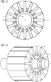
- a single segment rotor with only a single laminated core segment in the axial direction is in FIG. 14 shown schematically.
- FIG. 3 shows a single laminated core segment 3, is cut off for better representation of its structure, a partial section at the front corner.
- a laminated core segment 3 has approximately a triangular cross-section.
- the tip thereof forms the foot 6, which faces the shaft 1.
- On the foot 6 are located on both sides of the middle Fixierkonturen 7.
- each laminated core segment 3 represent the boundary surfaces of magnetic pockets 9, which are each formed between two laminated core segments 3 (see. FIG. 2 ).
- Positioning aids 11 for the permanent magnets to be inserted are arranged in the area of the foot 6 and in the region of the head 10 of the laminated core segment 3.
- the positioning aids 11 in the region of the head 10 form a positive connection with the magnets to be inserted, so that they are prevented from slipping out radially.
- a laminated core segment 3 In a laminated core segment 3, one or more cavities may be formed.
- a single cavity 13 In FIG. 2 for each laminated core segment 3 apart from positioning holes 12 only a single cavity 13 can be seen.
- a second cavity 14 indicated behind an end plate 15.
- a single sheet has an additional third cavity.
- the individual cavities are separated from each other.
- Such a cavity may serve to insert a carrier to stabilize the laminated core segment or runner.
- a carrier may be formed by pouring the cavity through the nonmagnetic material (permeability ⁇ r less than 5). In this case, it is necessary that the respective cavity is not closed by an end plate 15 (see. FIG. 2 ).
- the cavity can also be used to reduce the mass of the rotor and thus to reduce its inertia. In this case, it is closed by the end plate 15 (see. FIG. 3 ).
- the laminated core segment 3 here has the already mentioned holes 12, one in the region of the foot 6 and one in the region of the head 10 of the laminated core segment 3. These holes 12 are used for positioning the laminated core segments in the mold and, for example, for joining the spacer sleeves 5.
- FIG. 4 is the arrangement of FIG. 2 shown, wherein in the magnetic pockets 9 permanent magnets 16 are inserted, which have the same axial length as the individual laminated core segments 3.
- the permanent magnets 16 can be reliably positioned between the laminated core segments 3 via the joining aids 11.
- the open at the end faces of the individual laminations 3 cavities 13 can be filled with the appropriate molding compound, which then forms the corresponding carrier.
- the cavities 13 may also be filled with steel or other molding compound (e.g., carbon fiber reinforced plastic or foam).
- the runner can be further modified to meet his requirements.
- the mold is closed and the molding compound (plastic, aluminum, fiber-reinforced plastic, etc.) is introduced. This fills the cavities and thus forms a solid bond, which holds the runner together.
- the molding compound plastic, aluminum, fiber-reinforced plastic, etc.
- FIG. 5 now shows the finished single segment rotor after injection molding. Due to the molding compound end plates 17 are formed on the front sides of the rotor. The gap between the two Blechpersegmentringen 4 is filled by a cutting disc 18, which also consists of the molding material.
- FIG. 6 is a cross section through the finished single segment runner of FIG. 5 represented, and in FIG. 7 the runner with a partial section.
- FIG. 6 to see how the fixing contours 7 are enclosed by molding compound 19, which also forms a ring or an inner sleeve 19 around the shaft 2 provided with grooves 2.
- the closed cavities 14 are not filled with the molding compound, while the open during injection molding cavities 13 are now filled with the molding compound.
- the End plates 17 and the blade 18 formed from the molding compound.
- individual sheet metal segments or laminated core segments 3 are used to achieve a low-dispersion structure.
- FIGS. 8 to 14 show a simplified manufacturing process for a single segment rotor.
- one-piece, annular plates used with appropriate punched Such a sheet 20 has, for example, in FIG. 8 illustrated contour. The same contour results for the entire blanks package, as it is positioned together with the shaft 1 in the mold.
- laminated core segments 3 is part of the one-piece sheet 20.
- the individual sheets are connected in pairs on the outer circumference of the annular plate 20 with first webs 21.
- they are connected to the center of the annular plate 20, so the axis of the shaft 1 facing side of the sheet 20 via a second web 22 in pairs. Two adjacent individual sheets are thus connected to a first web 21 and a second web 22.
- all laminated core segments 3 are connected to each other annularly. Between the webs 21 and 22, the magnetic pockets 9 are formed here as well.
- the fixing contours 23 necessary for fixing the laminated core segments 3 are not arranged on the outside of the respective laminated core segments 3, but rather in their interior.
- the Fixierkonturen 23 here have a T-shaped cross-section, and they also form an undercut for the introduced molding compound, so that a positive connection is achieved with which the laminated core segments 3 are held on the shaft 1.
- the foot of the "T" of all fixing contours 23 points to the axis of the shaft first
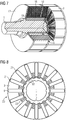
- FIG. 9 now shows the arrangement of FIG. 8 after pouring.
- the space between the shaft 1 and the inside of the Entire laminated core is poured out and forms the inner sleeve 19.
- the potting or molding compound is again non-magnetic and as in the previous embodiment of aluminum, stainless steel, plastic or the like formed.
- the fixing contours 23 are also filled with the molding compound, since they are open to the shaft.
- the inner sleeve 19 has corresponding extensions 24 which protrude into the Fixierkonturen 23 and produce the positive connection.
- FIG. 10 also shows that the fixing contours 23 can not only have a T-shaped cross-section. Rather, they may for example also have a mushroom-shaped or other cross-section. It is only essential that at least one undercut for the radial fixation of the respective laminated core segment 3 is present.
- the opening of the outer, ie the first webs 21 of the sheet metal section is carried out by a turning or milling.
- the result is in FIG. 11 shown.
- the processing of the outer periphery has the advantage that thereby the required air gap between rotor and stator can be made precise and therefore small.
- the opening of the first webs 21 can be done immediately by turning.
- the outer diameter is first machined by turning and then the outer webs are opened by a milling operation.
- the laminated core segments 3 are already separated from each other on the outside.
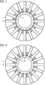
- FIG. 12 shows the result of the next processing step, in which the inner, ie the second webs 22 are removed.
- the dashed circle 26 illustrates that the second web 22 has been removed.
- the removal of the second web 22 in each magnetic pocket 9 and the exact definition of the magnetic seat can be done by a milling.
- the permanent magnets 16 inserted into the magnetic pockets 9. Radially outward, the magnets 16 are held by the positioning aids 11, which thus form a positive connection with the magnets 16.
- FIG. 14 shows the single segment runner in its final phase after production. Along with FIG. 13 It can be clearly seen that the extensions 24 on the inner ring 19 fix the laminated core segments 3 to the shaft 1. These in turn fix the permanent magnets 16 radially and in the circumferential direction.
- the rotor core is produced by using one-piece rotor laminations at the beginning.
- a runner is produced that meets all requirements.
- the arrangement of the magnets according to the flux concentration principle allows optimum flow control.
- a precise outer diameter and thus a very small air gap in the engine can be realized because the tolerance chain practically consists of only one part. Due to the reduction in the number of rotor parts results in a simple assembly and thus a production process suitable for production.
Landscapes
- Engineering & Computer Science (AREA)
- Power Engineering (AREA)
- Manufacturing & Machinery (AREA)
- Permanent Field Magnets Of Synchronous Machinery (AREA)
- Manufacture Of Motors, Generators (AREA)
- Iron Core Of Rotating Electric Machines (AREA)
Description
- Die vorliegende Erfindung betrifft ein Verfahren zum Herstellen eines Einzelsegmentläufers für eine elektrische Maschine. Darüber hinaus betrifft die vorliegende Erfindung einen entsprechenden Einzelsegmentläufer.
- Einzelsegmentläufer für Elektromotoren mit Flusskonzentration zeichnen sich dadurch aus, dass der Läufer sternförmig mit Permanentmagneten bestückt ist und der Zwischenraum zwischen den einzelnen Permanentmagneten jeweils durch ein ferromagnetisches Einzelsegment gefüllt ist. Ein solches Einzelsegment wird üblicherweise als Blechpaket gefertigt und kann daher als Blechpaketsegment bezeichnet werden. Die einzelnen Blechpaketsegmente sind, wenn möglich, nicht miteinander verbunden.
- Der Aufbau und die Fertigung eines Elektromotors mit Magneten in Flusskonzentration bedarf spezieller Techniken. Insbesondere sollte der Aufbau streuungsarm sein und für eine Serienproduktion geeignet sein. Da ein streuungsarmer Aufbau in der Regel die Verwendung von Blecheinzelsegmenten, d.h. Blechpaketsegmenten erfordert und so einen erhöhten Fertigungsaufwand mit sich führt, konkurriert ein solcher Aufbau mit einem Serienfertigungsprozess.
- Bisherige Ausführungen entsprechender Rotoren sind ein Kompromiss zwischen Einzelsegmenten einerseits und Rotorblechen andererseits, die untereinander verbunden sind. Mit kompletten Rotorblechen wird erreicht, dass das Rotorblechpaket mechanisch stabiler und einfacher herstellbar wird, aber ein Teil des Flusses der Magnete kurzgeschlossen wird. Möglich wird dies, z.B. durch stanzpaketierte Läuferpakete, bei denen in definierten Abständen die inneren Unterbrechungsstege erhalten bleiben. Einzelsegmente, wie sie beispielsweise in der nachveröffentlichten europäischen Patentanmeldung
EP 12 159 917.9 - Darüber hinaus muss bei einem Einzelsegmentläufer mit Flusskonzentration das Rotorblech durch "amagnetisches" Material (Permeabilitätszahl µ r kleiner 5) zwischen jedem Pol getrennt aufgebaut werden. Dies führt zu einer hohen Anzahl von Einzelsegmenten, die zusammengefügt werden müssen. Dabei entstehen Probleme wegen der komplizierten Herstellung der Einzelsegmente und des komplizierten Zusammenfügens der Einzelsegmente. Außerdem muss durch das amagnetische Material eine getrennte Flussführung realisiert werden. Weiterhin ergeben sich Probleme hinsichtlich des Positionierens und Haltens der Magnete sowie der Momentenübertragung.
- Bisherige Ausführungen sind ein Kompromiss zwischen Einzelsegmenten und Rotorblechen, die untereinander verbunden sind. So wird erreicht, dass das Rotorpaket mechanisch stabiler und leichter herstellbar wird, aber ein Teil des Flusses der Magnete kurzgeschlossen wird. Möglich wird dies, z. B. durch stanzpaketierte Läuferpakete, bei denen immer wieder die inneren Unterbrechungsstege erhalten bleiben.
- Die gattungsgemäße Druckschrift
DE 102 19 190 A1 beschreibt einen Permanentmagnet-Rotor für eine elektrische Maschine, bei dem strahlenförmig um eine Welle angeordnete Magnete und dazwischen angeordnete Flussleitstücke mit im wesentlichen kreissegmentförmigem Querschnitt zwischen zwei mit der Welle verbundenen Deckscheiben gehalten und mittels stabförmiger Halteelemente fixiert werden, die durch Aussparungen in den Flussleitstücken geführt und mit den Deckplatten verbunden sind. Ein solcher Motor wird gegen Wirbelstromverluste geschützt, indem die stabförmigen Halteelemente und die Deckplatten als einstückig in einem Spritzgussverfahren gefertigtes Bauteil aus Kunststoff oder einem anderen nicht magnetischen und elektrisch nicht leitenden Material ausgebildet sind. - Ein weiteres Verfahren und eine permanentmagneterregte Baugruppe einer elektrischen Maschine sind aus der
DE 198 46 924 A1 bekannt. Darin wird ein Verfahren zur Herstellung einer permanentmagneterregten Baugruppe insbesondere einer Synchronmaschine mit einem zylindrischen oder linearen ferromagnetischen Körper und darin angeordnete Permanentmagnete beschrieben, wobei einteilige Blechroden oder Blechstreifen spezieller Form mit Nuten und Zähnen zu einem Blechpaket geschichtet werden und ein Verfestigen der Blechroden oder Blechstreifen untereinander mittels eines nicht ferromagnetischen Materials durchgeführt wird. - In der Druckschrift
US 2006/0061227 A1 ist ein Speichen-Permanentmagnetrotor beschrieben, welcher eine unmagnetische Endkappe aufweist, welche mit einer Welle und einem ferromagnetischen Polschuh verbunden ist. Eine zweite unmagnetische Endkappe ist so angeordnet, dass der Polschuh zwischen der ersten und der zweiten Endkappe angeordnet ist. - In der Druckschrift
EP 1 100 175 A2 ist ein Rotor einer rotierenden Maschine beschrieben, welches ein unmagnetisches Teil aufweist, das an der Welle befestigt ist. Zudem weist der Rotor Permanentmagnete und Blechpakete auf, welche mit dem unmagnetischen Teil verbunden sind und radial und abwechselnd umlaufend miteinander angeordnet sind. - Die Aufgabe der vorliegenden Erfindung besteht darin, ein Verfahren bereitzustellen, mit dem ein Einzelsegmentläufer für eine elektrische Maschine mit weniger Aufwand hergestellt werden kann.
- Erfindungsgemäß wird diese Aufgabe gelöst durch ein Verfahren nach Patentanspruch 1.
- In vorteilhafter Weise werden also die Blechpaketsegmente jeweils mit mindestens einer Fixierkontur (z.B. Hinterschneidung bzgl. der auf das Blechpaketsegment wirkenden Zentrifugalkraft) versehen, und der Zwischenraum zwischen der Welle und den Blechpaketsegmenten wird mit einem aushärtbaren amagnetischen (Permeabilitätszahl µ r kleiner 5) Material ausgegossen. Dadurch ergibt sich zwischen dem ausgehärteten amagnetischem Material und den Fixierkonturen jeweils ein Formschluss, der das betreffende Blechpaketsegment an der Welle hält. Durch den Schritt des Ausgießens lassen sich also alle Blechpaketsegmente in einem Fertigungsschritt an der Welle fixieren.
- Das Anordnen der Blechpaketsegmente beinhaltet, dass eine Vielzahl an einteiligen, ringförmigen Blechen koaxial mit der Welle angeordnet werden, wobei jedes Blech je ein Einzelblech jedes der Blechpaketsegmente aufweist. Dadurch, dass die Einzelbleche der Blechpaketsegmente zunächst einteilig miteinander verbunden sind, sind sie einfach in dem Formwerkzeug zu platzieren.
- Jedes Blech ist an seinem Außenumfang vor dem Ausgießen durch erste Stege geschlossen, wobei diese ersten Stege nach dem Ausgießen beseitigt werden. Diese ersten Stege können besonders einfach entfernt werden, wenn sie am Außenumfang einer Blechscheibe liegen, welche die Einzelbleche beinhaltet.
- Jedes Blech besitzt am Umfang verteilt Magnetaussparungen, durch die zwischen den Blechpaketsegmenten Magnettaschen gebildet werden, in die die Permanentmagnete eingesteckt werden. Damit sind durch die Blechpaketsegmente die Positionen der Permanentmagnete automatisch vorgegeben.
- Des Weiteren ist jede Magnetaussparung an der zum Zentrum des jeweiligen ringförmigen Blechs weisenden Seite durch einen zweiten Steg geschlossen, sodass beim Ausgießen das amagnetische Material nicht in die Magnettaschen fließt, und die zweiten Stege können nach dem Ausgießen entfernt werden. Dadurch wird verhindert, dass amagnetisches Material beim Ausgießen in die Magnettaschen eindringt.
- Des Weiteren kann die Fixierkontur im Fuß jedes Blechpaketsegments, der zu der Welle gerichtet ist, mit einer Hinterschneidung realisiert werden, welche einer bei Rotation des Einzelsegmentläufers auf das jeweilige Blechpaketsegment wirkenden Zentrifugalkraft entgegenwirkt. Dadurch erfolgt die Fixierung der Blechpaketsegmente wellennah im Fuß des jeweiligen Blechpaketsegments.
- Ferner kann in jedem Blechpaketsegment ein Hohlraum durch korrespondierende Aussparungen in den Einzelblechen des Blechpaketsegments gebildet werden, welcher vor dem Schritt des Ausgießens an beiden Stirnseiten des Blechpaketsegments verschlossen wird, oder welcher mit dem amagnetischen Material ausgegossen wird. Durch den Hohlraum kann die Trägheit des Rotors reduziert werden. Andererseits kann der Hohlraum auch für die zusätzliche Fixierung des Rotors bzw. der Einzelbleche der Blechpaketsegmente genutzt werden.
- In einer Ausgestaltung können axial hintereinander mehrere Blechpaketsegmente jeweils getrennt durch einen vorgegebenen Abstand in dem Formwerkzeug angeordnet werden, und der durch den Abstand sich ergebende Zwischenraum lässt sich dann beim Ausgießen mitfüllen. Dadurch ergibt sich in axialer Richtung ein modularer Aufbau, womit sich auch stabile Rotoren größerer axialer Länge realisieren lassen.
- Zum Ausgießen kann als amagnetisches Material ein Kunststoff, insbesondere ein faserverstärkter Kunststoff oder Aluminium verwendet werden. Diese Stoffe zeichnen sich durch ihre geringe Dichte bei hoher Festigkeit aus. Dadurch kann ein stabiler Rotor mit geringem Gewicht realisiert werden.
- Die vorliegende Erfindung wird nun anhand der beigefügten Zeichnungen näher erläutert, in denen zeigen:
- FIG 1
- eine perspektivische Ansicht einer Welle für einen Rotor einer elektrischen Maschine;
- FIG 2
- um die Welle von
FIG 1 platzierte Blechpaketsegmente; - FIG 3
- ein einzelnes Blechpaketsegment mit einem Teilausschnitt;
- FIG 4
- die Anordnung von
FIG 2 mit eingefügten Permanentmagneten; - FIG 5
- die Anordnung von
FIG 4 nach dem Ausgießen mit amagnetischem Material; - FIG 6
- einen Querschnitt durch den Rotor von
FIG 5 ; - FIG 7
- den Rotor von
FIG 5 mit einem Teilausschnitt; - FIG 8
- ein einteiliges Blech mit zusammenhängenden Einzelblechen für jedes am Umfang angeordnete Blechpaketsegment;
- FIG 9
- eine Stirnseitenansicht eines mit Blechen gemäß
FIG 8 gefertigten Rotors nach dem Ausgießen mit amagnetischem Material; - FIG 10
- einen vergrößerten Ausschnitt von
FIG 9 mit Ausführungsvarianten; - FIG 11
- den Rotor von
FIG 9 mit abgedrehten ersten Stegen; - FIG 12
- den Rotor von
FIG 11 mit entfernten zweiten Stegen; - FIG 13
- den Rotor von
FIG 12 im Endzustand mit eingesetzten Permanentmagneten; und - FIG 14
- den Rotor von
FIG 13 in perspektivischer Ansicht. - Die nachfolgend näher geschilderten Ausführungsbeispiele stellen bevorzugte Ausführungsformen der vorliegenden Erfindung dar.
- In
FIG 1 ist eine Welle 1 dargestellt, die zur Herstellung eines Einzelsegmentläufers für eine elektrische Maschine geeignet ist. Die elektrische Maschine kann ein Motor oder ein Generator sein. Sie besitzt hier Nuten 2 oder andere geeignete Mittel zur Drehmomentenübertragung. - Die in
FIG 1 beispielhaft dargestellte Welle wird für die Herstellung des Einzelsegmentläufers in einem Formwerkzeug platziert. Das Formwerkzeug wird für ein Spritzgussverfahren verwendet. In dem Spritzgussverfahren wird die Welle 1 teilweise mit Kunststoff, insbesondere faserverstärktem Kunststoff, Aluminium oder dergleichen umspritzt. Das Formwerkzeug mit Positionierungsvorrichtung ist inFIG 1 wie auch in den folgenden Figuren nicht dargestellt. -
FIG 2 zeigt die Welle 1, um die zahlreiche Blechpaketsegmente 3 in dem nicht dargestellten Formwerkzeug platziert sind. Es sind hier 16 Blechpaketsegmente am Umfang gleichmäßig verteilt angeordnet. In axialer Richtung der Welle sind jeweils zwei Blechpaketsegmente 3 hintereinander angeordnet. Dadurch lassen sich größere axiale Baulängen von Einzelsegmentläufern realisieren. Auf diese Weise können auch mehr als zwei Blechpaketsegmente axial hintereinander angeordnet werden. Ein Einzelsegmentläufer mit nur einem einzigen Blechpaketsegment in axialer Richtung ist inFIG 14 schematisch wiedergegeben. - Gemäß dem Beispiel von
FIG 2 ergibt sich also ein modularer Aufbau mit zwei Blechpaketsegmentringen 4, die axial hintereinander angeordnet sind. Zwischen beiden Blechpaketsegmentringen 4 soll zur Stabilisierung eine Zwischenscheibe ausgebildet werden. Den dafür notwendigen Raum im Formwerkzeug schaffen Abstandshülsen 5 oder andere Abstandshalter zwischen den beiden Blechpaketsegmentringen 4. Die Abstandshülsen 5 werden während der Positionierung der Blechpaketsegmente 3 mit in das Formwerkzeug eingebracht. -
FIG 3 zeigt ein einzelnes Blechpaketsegment 3, von zur besseren Darstellung seiner Struktur ein Teilausschnitt an der vorderen Ecke abgeschnitten ist. Ein solches Blechpaketsegment 3 besitzt in etwa einen dreieckigen Querschnitt. Die Spitze davon bildet den Fuß 6, der der Welle 1 zugewandt ist. An dem Fuß 6 befinden sich beiderseits der Mitte Fixierkonturen 7. Im vorliegenden Beispiel sind es auf jeder Seite zwei Rillen, die in axialer Richtung verlaufen. Pro Rille ergibt sich damit eine Hinterschneidung, die einen Formschluss mit der einzugießenden Formmasse ermöglicht und damit verhindert, dass das Blechpaketsegment 3 in radialer Richtung von der Welle durch Zentrifugalkraft abgezogen wird. - Die Flanken 8 jedes Blechpaketsegments 3 stellen die Begrenzungsflächen von Magnettaschen 9 dar, die jeweils zwischen zwei Blechpaketsegmenten 3 gebildet sind (vgl.
FIG 2 ). Im Bereich des Fußes 6 und im Bereich des Kopfes 10 des Blechpaketsegments 3 sind Positionierhilfen 11 für die einzufügenden Permanentmagnete angeordnet. Die Positionierhilfen 11 im Bereich des Kopfes 10 bilden mit den einzusetzenden Magneten einen Formschluss, sodass diese an einem radialen Herausrutschen gehindert sind. - In einem Blechpaketsegment 3 können ein oder mehrere Hohlräume ausgebildet sein. In
FIG 2 ist bei jedem Blechpaketsegment 3 abgesehen von Positionierlöchern 12 nur ein einziger Hohlraum 13 zu erkennen. Im Beispiel vonFIG 3 ist ein zweiter Hohlraum 14 hinter einem Endblech 15 angedeutet. In dem Beispiel vonFIG 6 ist zu erkennen, dass hier ein Einzelblech einen zusätzlichen dritten Hohlraum aufweist. Die einzelnen Hohlräume sind voneinander getrennt. Ein solcher Hohlraum kann dazu dienen, einen Träger einzufügen, um das Blechpaketsegment bzw. den Läufer zu stabilisieren. Beispielsweise kann ein Träger dadurch gebildet werden, dass der Hohlraum durch das amagnetische Material (Permeabilitätszahl µ r kleiner 5) ausgegossen wird. In diesem Fall ist es notwendig, dass der jeweilige Hohlraum nicht durch ein Endblech 15 verschlossen wird (vgl.FIG 2 ). Der Hohlraum kann aber auch dazu benutzt werden, um die Masse des Läufers zu reduzieren und somit seine Trägheit zu verkleinern. In diesem Fall ist er durch das Endblech 15 zu verschließen (vgl.FIG 3 ). - Weiterhin verfügt das Blechpaketsegment 3 hier über die bereits erwähnten Löcher 12, eines im Bereich des Fußes 6 und eines im Bereich des Kopfes 10 des Blechpaketsegments 3. Diese Löcher 12 dienen zur Positionierung der Blechpaketsegmente im Formwerkzeug und beispielsweise zum Fügen der Abstandshülsen 5.
- In
FIG 4 ist die Anordnung vonFIG 2 dargestellt, wobei in die Magnettaschen 9 Permanentmagnete 16 eingefügt sind, die die gleiche axiale Länge wie die einzelnen Blechpaketsegmente 3 besitzen. Die Permanentmagnete 16 können über die Fügehilfen 11 zuverlässig zwischen den Blechpaketsegmenten 3 positioniert werden. - Für den folgenden Spritzgussvorgang können die an den Stirnseiten der Einzelblechpakete 3 offenen Hohlräume 13 mit der entsprechenden Formmasse gefüllt werden, die dann den entsprechenden Träger bildet. Alternativ können die Hohlräume 13 auch mit Stahl oder einer anderen Formmasse (z.B. kohlefaserverstärkter Kunststoff oder Schaum) gefüllt werden. Durch diesen Prozess kann der Läufer weiter auf seine Anforderungen hin modifiziert werden.
- Nachdem alle Komponenten im Formwerkzeug positioniert sind, wird das Werkzeug verschlossen und die Formmasse (Kunststoff, Aluminium, faserverstärkter Kunststoff etc.) eingebracht. Diese füllt die Hohlräume aus und bildet so einen festen Verbund, welcher den Läufer zusammenhält.
-
FIG 5 zeigt nun den fertig gestellten Einzelsegmentläufer nach dem Spritzguss. Durch die Formmasse sind an den Stirnseiten des Läufers Endscheiben 17 gebildet. Der Spalt zwischen den beiden Blechpaketsegmentringen 4 ist durch eine Trennscheibe 18, die ebenfalls aus der Formmasse besteht, gefüllt. - In
FIG 6 ist ein Querschnitt durch den fertig gestellten Einzelsegmentläufer vonFIG 5 dargestellt, und inFIG 7 der Läufer mit einem Teilausschnitt. Insbesondere ist derFIG 6 zu entnehmen, wie die Fixierungskonturen 7 durch Formmasse 19 umschlossen sind, welche außerdem einen Ring bzw. eine Innenhülse 19 um die mit Nuten 2 versehene Welle 1 bildet. Die abgeschlossenen Hohlräume 14 sind nicht mit der Formmasse gefüllt, während die beim Spritzgussvorgang offenen Hohlräume 13 nun mit der Formmasse gefüllt sind. Ferner sind auch die Endscheiben 17 sowie die Trennscheibe 18 aus der Formmasse gebildet. - Bei diesem ersten Ausführungsbeispiel werden also Blecheinzelsegmente bzw. Blechpaketsegmente 3 zur Erreichung eines streuungsarmen Aufbaus verwendet.
- Die
Figuren 8 bis 14 zeigen ein vereinfachtes Herstellungsverfahren für einen Einzelsegmentläufer. Dazu werden gemäßFIG 8 einteilige, ringförmige Bleche mit entsprechenden Ausstanzungen benutzt. Ein solches Blech 20 hat beispielsweise die inFIG 8 dargestellte Kontur. Die gleiche Kontur ergibt sich für das gesamte Rohblechpaket, wie es zusammen mit der Welle 1 in dem Formwerkzeug positioniert wird. Je ein Einzelblech aller am Umfang angeordneten Blechpaketsegmente 3 ist Teil des einteiligen Blechs 20. Die Einzelbleche sind am Außenumfang des ringförmigen Blechs 20 mit ersten Stegen 21 paarweise verbunden. Außerdem sind sie an der zum Zentrum des ringförmigen Blechs 20, also zur Achse der Welle 1 gewandten Seite des Blechs 20 über einen zweiten Steg 22 paarweise verbunden. Zwei benachbarte Einzelbleche sind also mit einem ersten Steg 21 und einem zweiten Steg 22 verbunden. Damit sind auch alle Blechpaketsegmente 3 ringförmig miteinander verbunden. Zwischen den Stegen 21 und 22 sind auch hier die Magnettaschen 9 ausgebildet. - In dem vorliegenden Ausführungsbeispiel sind die zur Fixierung der Blechpaketsegmente 3 notwendigen Fixierkonturen 23 nicht außen an den jeweiligen Blechpaketsegmenten 3, sondern in deren Innerem angeordnet. Die Fixierkonturen 23 besitzen hier einen T-förmigen Querschnitt, und sie bilden ebenfalls eine Hinterschneidung für die einzubringende Formmasse, sodass ein Formschluss erreicht wird, mit dem die Blechpaketsegmente 3 an der Welle 1 gehalten werden. Der Fuß des "T" aller Fixierkonturen 23 weist zur Achse der Welle 1.
-
FIG 9 zeigt nun die Anordnung vonFIG 8 nach dem Ausgießen. Der Zwischenraum zwischen der Welle 1 und der Innenseite des gesamten Blechpakets ist ausgegossen und bildet die Innenhülse 19. Die Verguss- bzw. Formmasse ist wiederum amagnetisch und wie in dem vorhergehenden Ausführungsbeispiel aus Aluminium, Edelstahl, Kunststoff oder dergleichen gebildet. Die Fixierkonturen 23 sind ebenfalls mit der Formmasse gefüllt, da sie ja zur Welle hin offen sind. Damit besitzt die Innenhülse 19 entsprechende Fortsätze 24, die in die Fixierkonturen 23 ragen und den Formschluss herstellen. - Wie in der vergrößerten Ansicht von
FIG 10 zu erkennen ist, verhindern die zweiten Stege 22, dass die Formmasse in die Magnettaschen 9 eindringt. Als Gussverfahren ist hier wie auch in den vorhergehenden Ausführungsbeispielen sowohl Druckguss als auch Kokilenguss möglich. Wird bei diesem Bearbeitungsschritt die Welle nicht gleichzeitig mit eingegossen, so muss sie zu einem späteren Zeitpunkt, z.B. durch Kaltfügen mit dem Rotorpaket verbunden werden. - Aus
FIG 10 geht außerdem hervor, dass die Fixierkonturen 23 nicht nur einen T-förmigen Querschnitt besitzen können. Vielmehr können sie beispielsweise auch einen pilzförmigen oder anderen Querschnitt besitzen. Wesentlich ist nur, dass mindestens eine Hinterschneidung für die radiale Fixierung des jeweiligen Blechpaketsegments 3 vorhanden ist. - In einem weiteren Bearbeitungsschritt erfolgt das Öffnen der äußeren, d.h. der ersten Stege 21 des Blechschnitts durch eine Dreh- bzw. Fräsbearbeitung. Das Resultat ist in
FIG 11 dargestellt. Die Bearbeitung des Außenumfangs hat den Vorteil, dass dadurch der geforderte Luftspalt zwischen Läufer und Ständer präzise und damit auch klein ausgeführt werden kann. Das Öffnen der ersten Stege 21 kann sofort durch die Drehbearbeitung erfolgen. Alternativ wird zuerst der Außendurchmesser durch Drehen bearbeitet und danach die äußeren Stege durch eine Fräsbearbeitung geöffnet. Nach diesem Bearbeitungsschritt sind die Blechpaketsegmente 3 außen bereits voneinander getrennt. -
FIG 12 zeigt das Ergebnis des nächsten Bearbeitungsschritts, bei dem die inneren, d.h. die zweiten Stege 22 entfernt sind. Der gestrichelte Kreis 26 verdeutlicht, dass der zweite Steg 22 entfernt wurde. Die Wegnahme des zweiten Stegs 22 in jeder Magnettasche 9 und die genaue Definition des Magnetsitzes kann durch eine Fräsbearbeitung erfolgen. - In einem anschließenden Schritt werden gemäß
FIG 13 die Permanentmagnete 16 in die Magnettaschen 9 eingesetzt. Radial nach außen werden die Magnete 16 durch die Positionierungshilfen 11 gehalten, die also mit den Magneten 16 einen Formschluss bilden. -
FIG 14 zeigt den Einzelsegmentläufer in seiner Endphase nach der Herstellung. Zusammen mitFIG 13 ist klar zu erkennen, dass die Fortsätze 24 am Innenring 19 die Blechpaketsegmente 3 an der Welle 1 fixieren. Diese wiederum fixieren die Permanentmagnete 16 radial und in Umfangsrichtung. - Bei dieser zweiten Ausführungsform wird also das Rotorpaket dadurch hergestellt, dass am Anfang einteilige Rotorbleche verwendet werden. Im Laufe der einzelnen Bearbeitungsschritte wird ein Läufer hergestellt, der alle Anforderungen erfüllt. Insbesondere ermöglicht die Anordnung der Magnete nach dem Flusskonzentrationsprinzip eine optimale Flussführung. Außerdem kann ein präziser Außendurchmesser und damit ein sehr kleiner Luftspalt im Motor realisiert werden, da die Toleranzkette praktisch nur aus einem Teil besteht. Aufgrund der Reduktion der Anzahl der Rotorteile ergibt sich eine einfache Montage und damit ein serientaugliches Fertigungsverfahren.
Claims (5)
- Verfahren zum Herstellen eines Einzelsegmentläufers für eine elektrische Maschine durch- Anordnen einer Welle (1) in einem Formwerkzeug,- Anordnen mehrerer, jeweils voneinander beabstandeter Blechpaketsegmente (3) am Umfang der Welle verteilt in dem Formwerkzeug, wobei die Blechpaketsegmente jeweils eine Fixierkontur (7,23) für einen Formschluss zu ihrer radialen Fixierung auf der Welle besitzen,- Anordnen je eines Permanentmagneten (16) zwischen jeweils zwei der Blechpaketsegmente (3),- Ausgießen eines Zwischenraums zwischen der Welle (1) und jeder Fixierkontur (7,23) der Blechpaketsegmente (3) durch ein aushärtbares amagnetisches Material, so dass- das ausgehärtete amagnetische Material mit jeder Fixierkontur bezogen auf die radiale Richtung einen Formschluss bildet und jedes Blechpaketsegment damit an der Welle gehalten wird, wobei- das Anordnen der Blechpaketsegmente (3) beinhaltet, dass eine Vielzahl an einteiligen, ringförmigen Blechen (20) koaxial mit der Welle (1) angeordnet wird, wobei jedes Blech (20) je ein Einzelblech jedes der Blechpaketsegmente (3) aufweist, wobei- jedes Blech (20) am Umfang verteilt Magnetaussparungen besitzt, durch die zwischen den Blechpaketsegmenten (3) Magnettaschen (9) gebildet werden, in die die Permanentmagnete (16) eingesteckt werden, und- jedes Blech (20) an seinem Außenumfang vor dem Ausgießen durch erste Stege (21) geschlossen ist, und nach dem Ausgießen die Stege (21) beseitigt werden,
dadurch gekennzeichnet, dass- jede Magnetaussparung an der zum Zentrum des jeweiligen ringförmigen Blechs (20) weisenden Seite durch einen zweiten Steg (22) geschlossen ist, sodass beim Ausgießen das amagnetische Material nicht in die Magnettaschen (9) fließt, und die zweiten Stege (22) nach dem Ausgießen entfernt werden. - Verfahren nach einem der vorhergehenden Ansprüche, wobei die Fixierkontur (7,23) im Fuß (6) jedes Blechpaketsegments (3), der zu der Welle (1) gerichtet ist, mit einer Hinterschneidung realisiert wird, welche einer bei der Rotation des Einzelsegmentläufers auf das jeweilige Blechpaketsegment (3) wirkende Zentrifugalkraft entgegenwirkt.
- Verfahren nach einem der vorhergehenden Ansprüche, wobei in jedem Blechpaketsegment (3) ein Hohlraum (13,14) durch korrespondierende Aussparungen in den Einzelblechen des Blechpaketsegments gebildet wird, welcher vor dem Schritt des Ausgießens an beiden Stirnseiten des Blechpaketsegments verschlossen wird, oder welcher mit dem amagnetischen Material ausgegossen wird.
- Verfahren nach einem der vorhergehenden Ansprüche, wobei axial hintereinander mehrere Blechpaketsegmente (3) jeweils getrennt durch einen vorgegebenen Abstand in dem Formwerkzeug angeordnet werden, und der durch den Abstand sich ergebende Zwischenraum beim Ausgießen mit ausgegossen wird.
- Verfahren nach einem der vorhergehenden Ansprüche, wobei zum Ausgießen ein Kunststoff, insbesondere ein faserverstärkter Kunststoff, oder Aluminium verwendet wird.
Priority Applications (1)
| Application Number | Priority Date | Filing Date | Title |
|---|---|---|---|
| EP13758779.6A EP2973946B1 (de) | 2013-04-16 | 2013-08-27 | Verfahren zum herstellen eines einzelsegmentläufers und entsprechender läufer |
Applications Claiming Priority (3)
| Application Number | Priority Date | Filing Date | Title |
|---|---|---|---|
| EP13163945 | 2013-04-16 | ||
| EP13758779.6A EP2973946B1 (de) | 2013-04-16 | 2013-08-27 | Verfahren zum herstellen eines einzelsegmentläufers und entsprechender läufer |
| PCT/EP2013/067658 WO2014169973A1 (de) | 2013-04-16 | 2013-08-27 | Verfahren zum herstellen eines einzelsegmentläufers und entsprechender läufer |
Publications (2)
| Publication Number | Publication Date |
|---|---|
| EP2973946A1 EP2973946A1 (de) | 2016-01-20 |
| EP2973946B1 true EP2973946B1 (de) | 2017-02-22 |
Family
ID=48139774
Family Applications (1)
| Application Number | Title | Priority Date | Filing Date |
|---|---|---|---|
| EP13758779.6A Active EP2973946B1 (de) | 2013-04-16 | 2013-08-27 | Verfahren zum herstellen eines einzelsegmentläufers und entsprechender läufer |
Country Status (4)
| Country | Link |
|---|---|
| US (1) | US9837881B2 (de) |
| EP (1) | EP2973946B1 (de) |
| CN (1) | CN105122599B (de) |
| WO (1) | WO2014169973A1 (de) |
Cited By (1)
| Publication number | Priority date | Publication date | Assignee | Title |
|---|---|---|---|---|
| WO2024255950A1 (de) * | 2023-06-16 | 2024-12-19 | Schaeffler Technologies AG & Co. KG | Rotor und elektrische maschine |
Families Citing this family (18)
| Publication number | Priority date | Publication date | Assignee | Title |
|---|---|---|---|---|
| EP3076524B1 (de) | 2015-03-30 | 2019-02-20 | Siemens Aktiengesellschaft | Maschinenkomponente einer elektrischen maschine und verfahren zu deren herstellung |
| JP6373505B2 (ja) * | 2015-08-12 | 2018-08-15 | 三菱電機株式会社 | 電動機及び空気調和機 |
| EP3139474A1 (de) | 2015-09-02 | 2017-03-08 | Siemens Aktiengesellschaft | Elektrische maschine und verfahren zum betrieb einer solchen elektrischen maschine sowie herstellverfahren |
| KR20170138105A (ko) * | 2016-06-07 | 2017-12-15 | 뉴모텍(주) | 스포크 타입 로터 |
| KR101945739B1 (ko) | 2017-11-07 | 2019-02-08 | 현대모비스 주식회사 | 모터장치의 회전자 |
| JP2019122196A (ja) * | 2018-01-10 | 2019-07-22 | 株式会社ミツバ | ロータ及びモータ |
| FR3080718B1 (fr) * | 2018-04-26 | 2021-04-23 | Valeo Equip Electr Moteur | Machine electrique tournante ayant une configuration reduisant les harmoniques du troisieme ordre |
| EP3595132A1 (de) * | 2018-07-13 | 2020-01-15 | Siemens Aktiengesellschaft | Materiallage für hohe drehzahlen und methode zu dessen herstellung |
| US11418074B2 (en) * | 2018-07-13 | 2022-08-16 | Abb Schweiz Ag | Rotary electrical machine with spoked rotor |
| US11791677B2 (en) * | 2020-01-20 | 2023-10-17 | Lc Advanced Motor Technology Corporation | Scalable rotor |
| CN112421906B (zh) * | 2020-12-18 | 2022-06-21 | 山东理工大学 | 带有蝙蝠形槽的单边止退模块化驱动电机转子生产方法 |
| EP4089885A1 (de) * | 2021-05-10 | 2022-11-16 | MAHLE International GmbH | Rotor für eine elektrische maschine |
| US12525831B2 (en) * | 2021-05-18 | 2026-01-13 | The Board Of Trustees Of The University Of Alabama | Ferrite spoke-type permanent magnet synchronous motor for electric trucks |
| CN113258690B (zh) * | 2021-06-04 | 2025-06-17 | 武汉理工通宇新源动力有限公司 | 一种轴向磁通电机定子及其制造方法 |
| DE102021118832A1 (de) | 2021-07-21 | 2023-01-26 | Knorr-Bremse Systeme für Nutzfahrzeuge GmbH | Rotor für eine elektrische Maschine, elektrische Maschine und Verfahren zum Betreiben einer elektrischen Maschine |
| DE102022117562A1 (de) * | 2022-07-14 | 2024-01-25 | Dr. Ing. H.C. F. Porsche Aktiengesellschaft | Rotoreinrichtung für eine elektrische Maschine und insbesondere für einen Fahrantrieb eines Kraftfahrzeugs sowie Verfahren zur Herstellung einer Rotoreinrichtung |
| DE102022212724A1 (de) * | 2022-11-28 | 2024-05-29 | M. L. DriveSolutions GmbH | Antrieb für ein leichtes Elektrofahrzeug und ein leichtes Elektrofahrzeug |
| CN119298455A (zh) * | 2023-07-10 | 2025-01-10 | 威灵(芜湖)电机制造有限公司 | 转子铁芯、转子组件及电机 |
Family Cites Families (13)
| Publication number | Priority date | Publication date | Assignee | Title |
|---|---|---|---|---|
| GB894405A (en) * | 1958-12-12 | 1962-04-18 | Plessey Co Ltd | Improvements in or relating to electric motors |
| FR2655784B1 (fr) * | 1989-12-08 | 1992-01-24 | Alsthom Gec | Moteur a aimants a concentration de flux. |
| US6259180B1 (en) * | 1996-07-02 | 2001-07-10 | Schlenker Enterprises, Ltd. | Motor including embedded permanent magnet rotor and method for making the same |
| DE19846924A1 (de) * | 1998-10-12 | 2000-04-13 | Sachsenwerk Gmbh | Permanentmagneterregte Baugruppe einer elektrischen Maschine und Verfahren zu ihrer Herstellung |
| JP2001136690A (ja) * | 1999-11-10 | 2001-05-18 | Isuzu Motors Ltd | 回転機のロータ |
| DE10219190A1 (de) * | 2002-04-29 | 2003-11-13 | Miele & Cie | Permanentmagnet-Rotor für eine elektrische Maschine |
| US7157827B2 (en) * | 2004-09-21 | 2007-01-02 | A. O. Smith Corporation | Spoke permanent magnet rotor |
| EP2523319B1 (de) | 2011-05-13 | 2013-12-18 | Siemens Aktiengesellschaft | Zylindrischer Linearmotor mit geringen Rastkräften |
| EP2523320A1 (de) | 2011-05-13 | 2012-11-14 | Siemens Aktiengesellschaft | Kombinationsantrieb für Dreh- und Hubbewegung und Linearmotor mit reduzierten Trägheiten |
| KR101786922B1 (ko) * | 2011-05-26 | 2017-10-18 | 삼성전자주식회사 | 로터 및 구동 모터 |
| CN102957237B (zh) * | 2011-08-22 | 2017-02-01 | 德昌电机(深圳)有限公司 | 无刷电机及其电机转子 |
| EP2639935B1 (de) | 2012-03-16 | 2014-11-26 | Siemens Aktiengesellschaft | Rotor mit Permanenterregung, elektrische Maschine mit einem solchen Rotor und Herstellungsverfahren für den Rotor |
| EP2793363A1 (de) * | 2013-04-16 | 2014-10-22 | Siemens Aktiengesellschaft | Einzelsegmentläufer mit Halteringen |
-
2013
- 2013-08-27 CN CN201380075682.6A patent/CN105122599B/zh active Active
- 2013-08-27 EP EP13758779.6A patent/EP2973946B1/de active Active
- 2013-08-27 US US14/784,603 patent/US9837881B2/en active Active
- 2013-08-27 WO PCT/EP2013/067658 patent/WO2014169973A1/de not_active Ceased
Non-Patent Citations (1)
| Title |
|---|
| None * |
Cited By (2)
| Publication number | Priority date | Publication date | Assignee | Title |
|---|---|---|---|---|
| WO2024255950A1 (de) * | 2023-06-16 | 2024-12-19 | Schaeffler Technologies AG & Co. KG | Rotor und elektrische maschine |
| DE102023115829A1 (de) * | 2023-06-16 | 2024-12-19 | Schaeffler Technologies AG & Co. KG | Rotor und elektrische Maschine |
Also Published As
| Publication number | Publication date |
|---|---|
| US9837881B2 (en) | 2017-12-05 |
| CN105122599B (zh) | 2017-11-17 |
| CN105122599A (zh) | 2015-12-02 |
| EP2973946A1 (de) | 2016-01-20 |
| US20160079832A1 (en) | 2016-03-17 |
| WO2014169973A1 (de) | 2014-10-23 |
Similar Documents
| Publication | Publication Date | Title |
|---|---|---|
| EP2973946A1 (de) | Verfahren zum herstellen eines einzelsegmentläufers und entsprechender läufer | |
| EP2961039B1 (de) | Mechanisch stabilisierter Rotor für einen Reluktanzmotor | |
| DE102004017157B4 (de) | Verfahren zur Herstellung einer Rotoranordnung und Rotoranordnung für eine elektrische Maschine | |
| EP3103183B1 (de) | Reluktanzrotor mit mechanischer stabilisierung | |
| EP3084936B1 (de) | Reluktanzrotor aufweisend ein reluktanzrotorblech mit aussparung zur spannungsreduktion | |
| EP0994550B1 (de) | Permanentmagneterregte Baugruppe einer elektrischen Maschine und Verfahren zu ihrer Herstellung | |
| EP2639935B1 (de) | Rotor mit Permanenterregung, elektrische Maschine mit einem solchen Rotor und Herstellungsverfahren für den Rotor | |
| DE102005013674A1 (de) | Rotor für bürstenlosen Motor und bürstenloser Motor | |
| DE102019127583A1 (de) | Rotoreinrichtung und Verfahren zur Herstellung einer Rotoreinrichtung für eine elektrische Maschine, insbesondere für einen Fahrzeugantrieb für ein Elektrofahrzeug | |
| EP3266096B1 (de) | Rotor für einen elektromotor, zugehörige motorwelle sowie verfahren zu deren herstellung | |
| EP2999087B1 (de) | Elektrische Maschine mit geringer magnetischer Nutstreuung | |
| DE102013101956A1 (de) | Rotor | |
| EP2965403B1 (de) | Rotor für einen reluktanzmotor, verfahren zum herstellen eines rotors für einen reluktanzmotor sowie elektrische maschine, insbesondere ein reluktanzmotor | |
| DE102010061784A1 (de) | Optimierter Speichenrotor | |
| DE102009029065A1 (de) | Elektrische Maschine mit reduziertem Rastmoment, insbesondere permanentmagneterregte Synchronmaschine | |
| EP2790296A1 (de) | Reluktanzmotor mit stabilisiertem Rotor | |
| EP3322073A1 (de) | Positives wuchten eines läufers | |
| EP3157140B1 (de) | Drehmomentoptimierter rotor und elektrokleinmotor mit einem derartigen rotor | |
| EP2999090B1 (de) | Permanenterregter Läufer mit geführtem Magnetfeld | |
| DE102016214542A1 (de) | Rotor für eine Synchron-Reluktanzmaschine | |
| WO2014166826A2 (de) | Reluktanzmotor mit stabilisiertem rotor | |
| EP3669440B1 (de) | Rotor einer elektrischen maschine | |
| EP2725688B1 (de) | Rotor für einen Elektromotor | |
| DE102012218993A1 (de) | Läuferanordnung für eine permanentmagneterregte elektrische Maschine | |
| DE102012218995A1 (de) | Läuferanordnung für eine permanentmagneterregte elektrische Maschine |
Legal Events
| Date | Code | Title | Description |
|---|---|---|---|
| PUAI | Public reference made under article 153(3) epc to a published international application that has entered the european phase |
Free format text: ORIGINAL CODE: 0009012 |
|
| 17P | Request for examination filed |
Effective date: 20151012 |
|
| AK | Designated contracting states |
Kind code of ref document: A1 Designated state(s): AL AT BE BG CH CY CZ DE DK EE ES FI FR GB GR HR HU IE IS IT LI LT LU LV MC MK MT NL NO PL PT RO RS SE SI SK SM TR |
|
| AX | Request for extension of the european patent |
Extension state: BA ME |
|
| DAX | Request for extension of the european patent (deleted) | ||
| GRAP | Despatch of communication of intention to grant a patent |
Free format text: ORIGINAL CODE: EPIDOSNIGR1 |
|
| INTG | Intention to grant announced |
Effective date: 20160912 |
|
| GRAS | Grant fee paid |
Free format text: ORIGINAL CODE: EPIDOSNIGR3 |
|
| GRAA | (expected) grant |
Free format text: ORIGINAL CODE: 0009210 |
|
| AK | Designated contracting states |
Kind code of ref document: B1 Designated state(s): AL AT BE BG CH CY CZ DE DK EE ES FI FR GB GR HR HU IE IS IT LI LT LU LV MC MK MT NL NO PL PT RO RS SE SI SK SM TR |
|
| REG | Reference to a national code |
Ref country code: GB Ref legal event code: FG4D Free format text: NOT ENGLISH |
|
| REG | Reference to a national code |
Ref country code: CH Ref legal event code: EP |
|
| REG | Reference to a national code |
Ref country code: AT Ref legal event code: REF Ref document number: 869971 Country of ref document: AT Kind code of ref document: T Effective date: 20170315 |
|
| REG | Reference to a national code |
Ref country code: IE Ref legal event code: FG4D Free format text: LANGUAGE OF EP DOCUMENT: GERMAN |
|
| REG | Reference to a national code |
Ref country code: DE Ref legal event code: R096 Ref document number: 502013006442 Country of ref document: DE |
|
| REG | Reference to a national code |
Ref country code: CH Ref legal event code: NV Representative=s name: SIEMENS SCHWEIZ AG, CH |
|
| REG | Reference to a national code |
Ref country code: LT Ref legal event code: MG4D |
|
| REG | Reference to a national code |
Ref country code: NL Ref legal event code: MP Effective date: 20170222 |
|
| PG25 | Lapsed in a contracting state [announced via postgrant information from national office to epo] |
Ref country code: FI Free format text: LAPSE BECAUSE OF FAILURE TO SUBMIT A TRANSLATION OF THE DESCRIPTION OR TO PAY THE FEE WITHIN THE PRESCRIBED TIME-LIMIT Effective date: 20170222 Ref country code: HR Free format text: LAPSE BECAUSE OF FAILURE TO SUBMIT A TRANSLATION OF THE DESCRIPTION OR TO PAY THE FEE WITHIN THE PRESCRIBED TIME-LIMIT Effective date: 20170222 Ref country code: LT Free format text: LAPSE BECAUSE OF FAILURE TO SUBMIT A TRANSLATION OF THE DESCRIPTION OR TO PAY THE FEE WITHIN THE PRESCRIBED TIME-LIMIT Effective date: 20170222 Ref country code: NO Free format text: LAPSE BECAUSE OF FAILURE TO SUBMIT A TRANSLATION OF THE DESCRIPTION OR TO PAY THE FEE WITHIN THE PRESCRIBED TIME-LIMIT Effective date: 20170522 Ref country code: GR Free format text: LAPSE BECAUSE OF FAILURE TO SUBMIT A TRANSLATION OF THE DESCRIPTION OR TO PAY THE FEE WITHIN THE PRESCRIBED TIME-LIMIT Effective date: 20170523 |
|
| REG | Reference to a national code |
Ref country code: FR Ref legal event code: PLFP Year of fee payment: 5 |
|
| RAP2 | Party data changed (patent owner data changed or rights of a patent transferred) |
Owner name: SIEMENS AKTIENGESELLSCHAFT |
|
| PG25 | Lapsed in a contracting state [announced via postgrant information from national office to epo] |
Ref country code: SE Free format text: LAPSE BECAUSE OF FAILURE TO SUBMIT A TRANSLATION OF THE DESCRIPTION OR TO PAY THE FEE WITHIN THE PRESCRIBED TIME-LIMIT Effective date: 20170222 Ref country code: LV Free format text: LAPSE BECAUSE OF FAILURE TO SUBMIT A TRANSLATION OF THE DESCRIPTION OR TO PAY THE FEE WITHIN THE PRESCRIBED TIME-LIMIT Effective date: 20170222 Ref country code: PT Free format text: LAPSE BECAUSE OF FAILURE TO SUBMIT A TRANSLATION OF THE DESCRIPTION OR TO PAY THE FEE WITHIN THE PRESCRIBED TIME-LIMIT Effective date: 20170622 Ref country code: RS Free format text: LAPSE BECAUSE OF FAILURE TO SUBMIT A TRANSLATION OF THE DESCRIPTION OR TO PAY THE FEE WITHIN THE PRESCRIBED TIME-LIMIT Effective date: 20170222 Ref country code: BG Free format text: LAPSE BECAUSE OF FAILURE TO SUBMIT A TRANSLATION OF THE DESCRIPTION OR TO PAY THE FEE WITHIN THE PRESCRIBED TIME-LIMIT Effective date: 20170522 Ref country code: NL Free format text: LAPSE BECAUSE OF NON-PAYMENT OF DUE FEES Effective date: 20170222 Ref country code: ES Free format text: LAPSE BECAUSE OF FAILURE TO SUBMIT A TRANSLATION OF THE DESCRIPTION OR TO PAY THE FEE WITHIN THE PRESCRIBED TIME-LIMIT Effective date: 20170222 |
|
| REG | Reference to a national code |
Ref country code: CH Ref legal event code: PCOW Free format text: NEW ADDRESS: WERNER-VON-SIEMENS-STRASSE 1, 80333 MUENCHEN (DE) |
|
| PG25 | Lapsed in a contracting state [announced via postgrant information from national office to epo] |
Ref country code: CZ Free format text: LAPSE BECAUSE OF FAILURE TO SUBMIT A TRANSLATION OF THE DESCRIPTION OR TO PAY THE FEE WITHIN THE PRESCRIBED TIME-LIMIT Effective date: 20170222 Ref country code: SK Free format text: LAPSE BECAUSE OF FAILURE TO SUBMIT A TRANSLATION OF THE DESCRIPTION OR TO PAY THE FEE WITHIN THE PRESCRIBED TIME-LIMIT Effective date: 20170222 Ref country code: EE Free format text: LAPSE BECAUSE OF FAILURE TO SUBMIT A TRANSLATION OF THE DESCRIPTION OR TO PAY THE FEE WITHIN THE PRESCRIBED TIME-LIMIT Effective date: 20170222 Ref country code: RO Free format text: LAPSE BECAUSE OF FAILURE TO SUBMIT A TRANSLATION OF THE DESCRIPTION OR TO PAY THE FEE WITHIN THE PRESCRIBED TIME-LIMIT Effective date: 20170222 |
|
| REG | Reference to a national code |
Ref country code: DE Ref legal event code: R097 Ref document number: 502013006442 Country of ref document: DE |
|
| PG25 | Lapsed in a contracting state [announced via postgrant information from national office to epo] |
Ref country code: SM Free format text: LAPSE BECAUSE OF FAILURE TO SUBMIT A TRANSLATION OF THE DESCRIPTION OR TO PAY THE FEE WITHIN THE PRESCRIBED TIME-LIMIT Effective date: 20170222 Ref country code: PL Free format text: LAPSE BECAUSE OF FAILURE TO SUBMIT A TRANSLATION OF THE DESCRIPTION OR TO PAY THE FEE WITHIN THE PRESCRIBED TIME-LIMIT Effective date: 20170222 Ref country code: DK Free format text: LAPSE BECAUSE OF FAILURE TO SUBMIT A TRANSLATION OF THE DESCRIPTION OR TO PAY THE FEE WITHIN THE PRESCRIBED TIME-LIMIT Effective date: 20170222 |
|
| PLBE | No opposition filed within time limit |
Free format text: ORIGINAL CODE: 0009261 |
|
| STAA | Information on the status of an ep patent application or granted ep patent |
Free format text: STATUS: NO OPPOSITION FILED WITHIN TIME LIMIT |
|
| 26N | No opposition filed |
Effective date: 20171123 |
|
| PG25 | Lapsed in a contracting state [announced via postgrant information from national office to epo] |
Ref country code: SI Free format text: LAPSE BECAUSE OF FAILURE TO SUBMIT A TRANSLATION OF THE DESCRIPTION OR TO PAY THE FEE WITHIN THE PRESCRIBED TIME-LIMIT Effective date: 20170222 |
|
| PG25 | Lapsed in a contracting state [announced via postgrant information from national office to epo] |
Ref country code: MC Free format text: LAPSE BECAUSE OF FAILURE TO SUBMIT A TRANSLATION OF THE DESCRIPTION OR TO PAY THE FEE WITHIN THE PRESCRIBED TIME-LIMIT Effective date: 20170222 |
|
| GBPC | Gb: european patent ceased through non-payment of renewal fee |
Effective date: 20170827 |
|
| REG | Reference to a national code |
Ref country code: IE Ref legal event code: MM4A |
|
| REG | Reference to a national code |
Ref country code: BE Ref legal event code: MM Effective date: 20170831 |
|
| PG25 | Lapsed in a contracting state [announced via postgrant information from national office to epo] |
Ref country code: LU Free format text: LAPSE BECAUSE OF NON-PAYMENT OF DUE FEES Effective date: 20170827 |
|
| PG25 | Lapsed in a contracting state [announced via postgrant information from national office to epo] |
Ref country code: IE Free format text: LAPSE BECAUSE OF NON-PAYMENT OF DUE FEES Effective date: 20170827 Ref country code: GB Free format text: LAPSE BECAUSE OF NON-PAYMENT OF DUE FEES Effective date: 20170827 |
|
| REG | Reference to a national code |
Ref country code: FR Ref legal event code: PLFP Year of fee payment: 6 |
|
| PG25 | Lapsed in a contracting state [announced via postgrant information from national office to epo] |
Ref country code: BE Free format text: LAPSE BECAUSE OF NON-PAYMENT OF DUE FEES Effective date: 20170831 |
|
| PG25 | Lapsed in a contracting state [announced via postgrant information from national office to epo] |
Ref country code: MT Free format text: LAPSE BECAUSE OF FAILURE TO SUBMIT A TRANSLATION OF THE DESCRIPTION OR TO PAY THE FEE WITHIN THE PRESCRIBED TIME-LIMIT Effective date: 20170222 |
|
| PG25 | Lapsed in a contracting state [announced via postgrant information from national office to epo] |
Ref country code: HU Free format text: LAPSE BECAUSE OF FAILURE TO SUBMIT A TRANSLATION OF THE DESCRIPTION OR TO PAY THE FEE WITHIN THE PRESCRIBED TIME-LIMIT; INVALID AB INITIO Effective date: 20130827 |
|
| PG25 | Lapsed in a contracting state [announced via postgrant information from national office to epo] |
Ref country code: CY Free format text: LAPSE BECAUSE OF FAILURE TO SUBMIT A TRANSLATION OF THE DESCRIPTION OR TO PAY THE FEE WITHIN THE PRESCRIBED TIME-LIMIT Effective date: 20170222 |
|
| PG25 | Lapsed in a contracting state [announced via postgrant information from national office to epo] |
Ref country code: MK Free format text: LAPSE BECAUSE OF FAILURE TO SUBMIT A TRANSLATION OF THE DESCRIPTION OR TO PAY THE FEE WITHIN THE PRESCRIBED TIME-LIMIT Effective date: 20170222 |
|
| PG25 | Lapsed in a contracting state [announced via postgrant information from national office to epo] |
Ref country code: TR Free format text: LAPSE BECAUSE OF FAILURE TO SUBMIT A TRANSLATION OF THE DESCRIPTION OR TO PAY THE FEE WITHIN THE PRESCRIBED TIME-LIMIT Effective date: 20170222 |
|
| PG25 | Lapsed in a contracting state [announced via postgrant information from national office to epo] |
Ref country code: AL Free format text: LAPSE BECAUSE OF FAILURE TO SUBMIT A TRANSLATION OF THE DESCRIPTION OR TO PAY THE FEE WITHIN THE PRESCRIBED TIME-LIMIT Effective date: 20170222 Ref country code: IS Free format text: LAPSE BECAUSE OF FAILURE TO SUBMIT A TRANSLATION OF THE DESCRIPTION OR TO PAY THE FEE WITHIN THE PRESCRIBED TIME-LIMIT Effective date: 20170622 |
|
| PGFP | Annual fee paid to national office [announced via postgrant information from national office to epo] |
Ref country code: AT Payment date: 20210708 Year of fee payment: 9 |
|
| PGFP | Annual fee paid to national office [announced via postgrant information from national office to epo] |
Ref country code: CH Payment date: 20211102 Year of fee payment: 9 |
|
| REG | Reference to a national code |
Ref country code: CH Ref legal event code: PL |
|
| REG | Reference to a national code |
Ref country code: AT Ref legal event code: MM01 Ref document number: 869971 Country of ref document: AT Kind code of ref document: T Effective date: 20220827 |
|
| PG25 | Lapsed in a contracting state [announced via postgrant information from national office to epo] |
Ref country code: LI Free format text: LAPSE BECAUSE OF NON-PAYMENT OF DUE FEES Effective date: 20220831 Ref country code: CH Free format text: LAPSE BECAUSE OF NON-PAYMENT OF DUE FEES Effective date: 20220831 Ref country code: AT Free format text: LAPSE BECAUSE OF NON-PAYMENT OF DUE FEES Effective date: 20220827 |
|
| PGFP | Annual fee paid to national office [announced via postgrant information from national office to epo] |
Ref country code: IT Payment date: 20250827 Year of fee payment: 13 |
|
| PGFP | Annual fee paid to national office [announced via postgrant information from national office to epo] |
Ref country code: FR Payment date: 20250827 Year of fee payment: 13 |
|
| PGFP | Annual fee paid to national office [announced via postgrant information from national office to epo] |
Ref country code: DE Payment date: 20251020 Year of fee payment: 13 |