EP2973233B1 - System, method and apparatus for encoding of rfid inlays - Google Patents
System, method and apparatus for encoding of rfid inlays Download PDFInfo
- Publication number
- EP2973233B1 EP2973233B1 EP14725561.6A EP14725561A EP2973233B1 EP 2973233 B1 EP2973233 B1 EP 2973233B1 EP 14725561 A EP14725561 A EP 14725561A EP 2973233 B1 EP2973233 B1 EP 2973233B1
- Authority
- EP
- European Patent Office
- Prior art keywords
- rfid
- encoding
- scanner
- indicia
- inlays
- Prior art date
- Legal status (The legal status is an assumption and is not a legal conclusion. Google has not performed a legal analysis and makes no representation as to the accuracy of the status listed.)
- Active
Links
- 238000000034 method Methods 0.000 title description 15
- 238000007639 printing Methods 0.000 claims description 22
- 230000007723 transport mechanism Effects 0.000 claims description 19
- 230000007246 mechanism Effects 0.000 claims description 10
- 239000000758 substrate Substances 0.000 claims description 9
- 238000004891 communication Methods 0.000 claims description 7
- 238000003860 storage Methods 0.000 claims description 6
- 238000005286 illumination Methods 0.000 claims description 4
- 239000000853 adhesive Substances 0.000 description 2
- 230000001070 adhesive effect Effects 0.000 description 2
- 230000002457 bidirectional effect Effects 0.000 description 2
- 238000006243 chemical reaction Methods 0.000 description 2
- 238000004519 manufacturing process Methods 0.000 description 2
- 238000012545 processing Methods 0.000 description 2
- YLJREFDVOIBQDA-UHFFFAOYSA-N tacrine Chemical compound C1=CC=C2C(N)=C(CCCC3)C3=NC2=C1 YLJREFDVOIBQDA-UHFFFAOYSA-N 0.000 description 2
- 229960001685 tacrine Drugs 0.000 description 2
- 238000012795 verification Methods 0.000 description 2
- 230000000007 visual effect Effects 0.000 description 2
- 235000000177 Indigofera tinctoria Nutrition 0.000 description 1
- 241001147416 Ursus maritimus Species 0.000 description 1
- 230000000712 assembly Effects 0.000 description 1
- 238000000429 assembly Methods 0.000 description 1
- 230000000295 complement effect Effects 0.000 description 1
- 238000006880 cross-coupling reaction Methods 0.000 description 1
- 238000010586 diagram Methods 0.000 description 1
- 238000009826 distribution Methods 0.000 description 1
- 238000005516 engineering process Methods 0.000 description 1
- 230000005284 excitation Effects 0.000 description 1
- 229940097275 indigo Drugs 0.000 description 1
- COHYTHOBJLSHDF-UHFFFAOYSA-N indigo powder Natural products N1C2=CC=CC=C2C(=O)C1=C1C(=O)C2=CC=CC=C2N1 COHYTHOBJLSHDF-UHFFFAOYSA-N 0.000 description 1
- 239000000463 material Substances 0.000 description 1
- 238000012015 optical character recognition Methods 0.000 description 1
- 230000003287 optical effect Effects 0.000 description 1
- 238000004806 packaging method and process Methods 0.000 description 1
- 238000003908 quality control method Methods 0.000 description 1
- 238000012360 testing method Methods 0.000 description 1
- 230000001131 transforming effect Effects 0.000 description 1
- 239000002699 waste material Substances 0.000 description 1
Images


Classifications
-
- G—PHYSICS
- G06—COMPUTING; CALCULATING OR COUNTING
- G06K—GRAPHICAL DATA READING; PRESENTATION OF DATA; RECORD CARRIERS; HANDLING RECORD CARRIERS
- G06K7/00—Methods or arrangements for sensing record carriers, e.g. for reading patterns
- G06K7/10—Methods or arrangements for sensing record carriers, e.g. for reading patterns by electromagnetic radiation, e.g. optical sensing; by corpuscular radiation
- G06K7/10009—Methods or arrangements for sensing record carriers, e.g. for reading patterns by electromagnetic radiation, e.g. optical sensing; by corpuscular radiation sensing by radiation using wavelengths larger than 0.1 mm, e.g. radio-waves or microwaves
-
- G—PHYSICS
- G06—COMPUTING; CALCULATING OR COUNTING
- G06K—GRAPHICAL DATA READING; PRESENTATION OF DATA; RECORD CARRIERS; HANDLING RECORD CARRIERS
- G06K1/00—Methods or arrangements for marking the record carrier in digital fashion
- G06K1/14—Methods or arrangements for marking the record carrier in digital fashion by transferring data from a similar or dissimilar record carrier
- G06K1/18—Methods or arrangements for marking the record carrier in digital fashion by transferring data from a similar or dissimilar record carrier by transferring data from one type of record carrier on to another type of record carrier, e.g. from magnetic tape to punched card
-
- G—PHYSICS
- G06—COMPUTING; CALCULATING OR COUNTING
- G06K—GRAPHICAL DATA READING; PRESENTATION OF DATA; RECORD CARRIERS; HANDLING RECORD CARRIERS
- G06K17/00—Methods or arrangements for effecting co-operative working between equipments covered by two or more of main groups G06K1/00 - G06K15/00, e.g. automatic card files incorporating conveying and reading operations
- G06K17/0022—Methods or arrangements for effecting co-operative working between equipments covered by two or more of main groups G06K1/00 - G06K15/00, e.g. automatic card files incorporating conveying and reading operations arrangements or provisious for transferring data to distant stations, e.g. from a sensing device
- G06K17/0025—Methods or arrangements for effecting co-operative working between equipments covered by two or more of main groups G06K1/00 - G06K15/00, e.g. automatic card files incorporating conveying and reading operations arrangements or provisious for transferring data to distant stations, e.g. from a sensing device the arrangement consisting of a wireless interrogation device in combination with a device for optically marking the record carrier
Definitions
- RFID inlays are typically incorporated into labels or card stock to form tags that can be applied to items or item packaging either directly through the use of adhesive or indirectly such as through a fastener, e.g. string, plastic tie, etc..
- Labels and tags incorporating RFID inlays can complement the advantages of RFID with visual indicia, such as barcodes, alphanumeric identifiers, descriptive text, variable and fixed, and pictographic information.
- visual indicia such as barcodes, alphanumeric identifiers, descriptive text, variable and fixed, and pictographic information.
- an apparel hang tag can incorporate an RFID inlay and can further include graphic information such as the brand of the product, fixed indicia such as product description, variable indicia such as product size, price, care, product identifying information such as a barcode, and so forth.
- US 2007/017988 A1 describes a device featuring an optical reader for printed codes capable of transforming the information of a code printed on an object such as a label into digital data, the object being equipped with a radiofrequency system featuring an antenna and a chip connected together.
- the device features a radiofrequency dialog unit designed to encode the chip with digital data read from the printed code and to compare the digital data encoded in the chip with information from the printed code.
- the objects 10 may be any desired object having an RFID inlay 20 therein and having indicia 30 disposed thereon.
- Objects 10 may further be substantially planar objects, having a plurality of laminated layers, with RFID inlays 20 laminated therein. Examples of such objects may be adhesive labels, apparel hang tags, tickets, and so forth.
- Objects 10 may further have indicia disposed thereon.
- the indicia 30 may include barcodes, which may be 1-dimensional or 2-dimensional barcodes, as well as other machine readable or scannable codes as well as alphanumeric information. Included in indicia 30 may be information for encoding the RFID inlays 20 disposed within the objects 10.
- the encoding data may be provided in any suitable format.
- this data may be a hexadecimal representation of the data that is to be programmed into the RFID tag or inlay.
- some or all of the indicia 30 may only be readable when illuminated by ultraviolet lighting.
- the indicia 30 may have an excitation wavelength of about 254 nm to about 365 nm, and an emission wavelength of about 614 nm.
- the feeder/encoding device 420 receives the individual RFID tags, tickets or labels and then scans the printed indicia and then encodes the individual RFID inlays as previously disclosed.
- Some sort of cutter (not shown), mechanical die cutter, laser cutter or the like may be included between the printer and feeder to cut the substrate, whether provided in a sheet or web form, into individual RFID tags, tickets and inlays.
- Information may also be received from the computer 410 such as verification of the EPC code to encode the RFID inlay so that it matches the indicia that was scanned from the printed portion of the substrate.
- the RFID tags, tickets and labels are then collected 430 in a stack to be distributed for subsequent attachment or association with consumer items such as apparel, garments, or other consumer goods.
Description
- The use of radio frequency identification (RFID) tags, tickets, labels and inlays to track, identify and locate goods has grown significantly in recent years. RFID tags allow manufacturers, distributors and retailers, amongst others, to regulate products and inventory, quickly determine production, manufacture, distribution or retail needs and efficiently intake and outtake items utilizing RFID tags. The RFID tags themselves can provide any desired product data and may be scanned or read in any of a variety of manners in order to retrieve the information contained on the chip on the RFID tag.
- RFID inlays are typically incorporated into labels or card stock to form tags that can be applied to items or item packaging either directly through the use of adhesive or indirectly such as through a fastener, e.g. string, plastic tie, etc.. Labels and tags incorporating RFID inlays can complement the advantages of RFID with visual indicia, such as barcodes, alphanumeric identifiers, descriptive text, variable and fixed, and pictographic information. For example, in a retail environment, an apparel hang tag can incorporate an RFID inlay and can further include graphic information such as the brand of the product, fixed indicia such as product description, variable indicia such as product size, price, care, product identifying information such as a barcode, and so forth.
- Typically, the visual indicia are imaged onto a sheet of labels by a printing press or similar printing platform, such as flexographic or gravure. Known RFID tag and ticket printing platforms do not have the ability to encode chips on RFID inlays. Certain labels incorporating RFID inlays exiting a printing platform may include pre-printed variable data for encoding a chip included with a RFID inlay. However, the chip on the RFID inlay must be encoded such that the encoded data matches the pre-printed variable data displayed on the label. If the printed information does not match the encoded information, the tag, inlay and printing are rejected and result in additional waste and cost to the brand owner and manufacturer.
-
EP 1 538 552 A2 describes a printing system capable of writing RFID data consistent with print information printed on a print-information recoding medium into a RFID chip carried on the print-information recording medium. The printing system includes a printer engine for printing print information, including at least either one of contactlessly readable information and image information visible to human being, onto at least the print-information recording medium, and an RFID reader/writer for writing RFID data consistent with the print information into the RFID chip carried on the print-information recording medium. -
US 2007/017988 A1 describes a device featuring an optical reader for printed codes capable of transforming the information of a code printed on an object such as a label into digital data, the object being equipped with a radiofrequency system featuring an antenna and a chip connected together. According to a main characteristic of the invention, the device features a radiofrequency dialog unit designed to encode the chip with digital data read from the printed code and to compare the digital data encoded in the chip with information from the printed code. -
US 2003/0057280 describes a method for processing transaction items in a serial fashion that allows sequences of transaction items to be produced in a specified and complete order. Accordingly, transaction items are produced one-at-a-time and creation of a next transaction item is not begun until a current transaction item is completed. - According to at least one example useful for understanding the invention, a system encoding a RFID tag, label or inlay incorporated in or with an object, the object having indicia disposed thereon, is described. The system can include an object transporting mechanism, a scanner for scanning the indicia, at least one RFID antenna for encoding the chip on the RFID inlay, and a processor in communication with and adapted to control the operation of the object transporting mechanism, the scanner, and the at least one RFID antenna.
- According to another example useful for understanding the invention, an apparatus for encoding a chip as part of a RFID tag, label or inlay incorporated in or associated with an object is described. The apparatus can include a digital printing platform for printing fixed and/or variable information and an object transporting mechanism for transporting the object from a first location to a second location, a scanner disposed between the first location and the second location, the scanner adapted to read encoding data present in indicia disposed on the object, and at least one RFID antenna disposed between the first location and the second location and in communication with the scanner, the at least one RFID antenna having read and write capabilities for encoding the chip with the RFID inlay based on the encoding data.
- According to another example useful for understanding the invention, a method for encoding a chip on a RFID inlay is described. The method can include providing an object incorporating an RFID inlay and having indicia disposed thereon, obtaining encoding data from the indicia, and encoding the chip on the RFID inlay with the encoding data.
- In a still further example useful for understanding the presently described invention, a system for producing RFID inlays for use as RFID tags, tickets and labels, is disclosed and includes a digital printing platform for printing variable and fixed indicia on a substrate containing a number of RFID inlays, with each of the inlays having a chip and antenna connected to the chip. The system further includes a computer connected to the digital printing platform to provide printing instructions to the digital printing platform; and a feeding and encoding device for feeding and encoding each of the RFID inlays and the feeding and encoding device connected to the computer to verify encoded information contained in one of the variable or fixed indicia.
- The problems of the prior art are solved by a system in accordance with any of claims 1-4.
- Advantages of embodiments of the present invention will be apparent from the following detailed description of the exemplary embodiments. The following detailed description should be considered in conjunction with the accompanying figures in which:
-
Fig. 1 shows a system for encoding RFID inlays; -
Fig. 2 shows an apparatus for encoding RFID inlays; -
Fig. 3 shows a method for encoding RFID inlays; and -
Fig. 4 provides a schematic of the system in accordance with the present invention. - Aspects of the invention are disclosed in the following description and related drawings directed to specific embodiments of the invention. Alternate embodiments may be devised without departing from the scope of the invention. Additionally, well-known elements of exemplary embodiments of the invention will not be described in detail or will be omitted so as not to obscure the relevant details of the invention. Further, to facilitate an understanding of the description discussion of several terms used herein follows.
- As used herein, the word "exemplary" means "serving as an example, instance or illustration." The embodiments described herein are not limiting, but rather are exemplary only. It should be understood that the described embodiment are not necessarily to be construed as preferred or advantageous over other embodiments. Moreover, the terms "embodiments of the invention", "embodiments" or "invention" do not require that all embodiments of the invention include the discussed feature, advantage or mode of operation.
- Further, many of the embodiments described herein are described in terms of sequences of actions to be performed by, for example, elements of a computing device. It should be recognized by those skilled in the art that the various sequence of actions described herein can be performed by specific circuits (e.g., application specific integrated circuits (ASICs)) and/or by program instructions executed by at least one processor. Additionally, the sequence of actions described herein can be embodied entirely within any form of computer-readable storage medium such that execution of the sequence of actions enables the processor to perform the functionality described herein. Thus, the various aspects of the present invention may be embodied in a number of different forms, all of which have been contemplated to be within the scope of the claimed subject matter. In addition, for each of the embodiments described herein, the corresponding form of any such embodiments may be described herein as, for example, "a computer configured to" perform the described action.
- According to at least one exemplary embodiment, a system, method and apparatus for encoding a chip on a RFID inlay is disclosed. The system may be adapted to encode RFID inlays that are incorporated into objects, for example RFID inlays laminated into labels, hang tags, or the like or intermediate assemblies that will become tags, labels or tickets. The objects can have indicia printed thereon, wherein the indicia include data that is to be encoded into the chip on the RFID inlay. The system may be adapted to read the printed indicia, convert the encoding data into a desired format such as EPC, and subsequently encode the RFID inlay with the converted encoding data. The system may further include quality control and error handling procedures, allowing the system to verify encoded RFID tags and reject the RFID tags that fail the verification test. The indicia is printed for example by using a digital printing platform which can vary the printed information from inlay to inlay or portion of a substrate to another portion of the substrate. For example, a sheet of material which may make up multiple hang tags or tickets, can be printed with fixed indicia and then each area that will become a separate ticket will have variable printing provided thereon.
-
Figure 1 is a diagram of asystem 100 for encoding of RFID inlays. When referring to encoding RFID inlays, tags, tickets or labels, this refers to encoding a chip or circuit that is applied to the surface of the inlay to which a RFID antenna is connected.System 100 can include atransport mechanism 102, ascanner 104, and at least oneRFID antenna 106. Each ofmechanism 102,scanner 104 andantenna 106 may be communicatively and operatively coupled to acomputing device 108 runningsoftware 110 for managing the RFID encoding process. Thecomputing device 108 can include aprocessor 112 for executingsoftware 110 and a non-transitory computerreadable medium 114 on whichsoftware 110 may be stored.Computing device 108 can further include at least one communications adapter for communicating withmechanism 102,scanner 104 andantenna 106. Thecomputing device 108 can also be connected to a printing device so as to coordinate the printing of indicia on the inlay. Communications betweencomputing device 108 andcomponents transport mechanism 102,scanner 104, andRFID antenna 106 may be provided in anencoding apparatus 200. In some examples,system 100 can further include anobject sensor 109, communicatively and operatively coupled tocomputing device 110, for detecting the presence of object ontransport mechanism 102.Object sensor 109 may be disposedproximate scanner 104. - Turning to
Figure 2 , anencoding apparatus 200 is shown. Thetransport mechanism 102 of the encoding apparatus can serve to transportobjects 10 having RFID inlays 20 incorporated therein from a first location to a second location. The transport mechanism may be any device that allowsapparatus 200 andsystem 100 to function as described herein. It may also be a device that can be connected to a printing device so as to enable continuous processing of the RFID tags, tickets, labels and inlay. In some exemplary embodiments,transport mechanism 102 may be a friction feeder assembly. Furthermore, in some exemplary embodiments, astorage receptacle 202 may be disposed proximate the first location, allowing a plurality ofobjects 10 to be stored therein prior to transport ontransport mechanism 102. A non-limiting example of a transport mechanism for use withsystem 100 andapparatus 200 is the Multifeeder® 250IP XLD friction feeder, available from Multifeeder Technology of White Bear Lake, MN, or a similar device. Additionally,transport mechanism 102 may be adapted to interface withcomputing device 108 andsoftware 110 such that the operation oftransport mechanism 102 may be controlled by computingdevice 108. The communication betweentransport mechanism 102 andcomputing device 108 may be bidirectional. In some exemplary embodiments, thetransport mechanism 102 andcomputing device 108 may communicate with each other via a standard command set. Such a command set may include, identifying commands, feed setup commands, fault commands, positioning commands, and state reset commands. - The
objects 10 may be any desired object having anRFID inlay 20 therein and havingindicia 30 disposed thereon.Objects 10 may further be substantially planar objects, having a plurality of laminated layers, with RFID inlays 20 laminated therein. Examples of such objects may be adhesive labels, apparel hang tags, tickets, and so forth.Objects 10 may further have indicia disposed thereon. Theindicia 30 may include barcodes, which may be 1-dimensional or 2-dimensional barcodes, as well as other machine readable or scannable codes as well as alphanumeric information. Included inindicia 30 may be information for encoding the RFID inlays 20 disposed within theobjects 10. The encoding data may be provided in any suitable format. In some exemplary embodiments, this data may be a hexadecimal representation of the data that is to be programmed into the RFID tag or inlay. Furthermore, some or all of theindicia 30 may only be readable when illuminated by ultraviolet lighting. In some exemplary embodiments, theindicia 30 may have an excitation wavelength of about 254 nm to about 365 nm, and an emission wavelength of about 614 nm. - Once placed on
transport mechanism 102, theobjects 10 can be transported pastscanner 104 and at least oneRFID antenna 106. Thetransport mechanism 102 and/orstorage receptacle 202 can be adapted to feedobjects 10 to thestorage mechanism 102 at predetermined feed intervals. The feed intervals can be determined so as to introduce spacing between any twoadjacent objects 10, with the spacing being of sufficient size such that interference and cross-coupling between the tags of any two adjacent objects can be minimized or eliminated. In some exemplary embodiments, theobjects 10 may be fed one-at-a-time fromstorage receptacle 202past scanner 104 and at least oneRFID antenna 106. Furthermore,transport mechanism 102 may have a length sufficient to allow the other components ofapparatus 202, such asscanner 104,illumination source 204, at least oneRFID antenna 106, and objectsensor 109 to be mounted thereon. -
Scanner 104 may be any known scanner that is capable of reading 1-dimensional and 2-dimensional barcodes in any format. In some exemplary embodiments,scanner 104 may also include optical character recognition capabilities so as to allowscanner 104 to read alphanumeric data. Anultraviolet illumination source 204 may be operatively coupled toscanner 104 so as to enablescanner 104 to read UV-sensitive barcodes. TheUV illumination source 204 may be adapted to emit light at wavelengths of between about 254 to about 365 nm. A non-limiting example of ascanner 104 for use withsystem 100 andapparatus 200 may be a 2-dimensional barcode scanner such as theCognex Dataman 300, available from Cognex Corporation of Needham, MA or similar device. - At least one
RFID antenna 106 may be adapted for writing to, reading, and locking RFID inlays. In some exemplary embodiments, the reading, writing and locking functionalities may be provided in asingle RFID antenna 106. In other exemplary embodiments, the reading, writing, and locking functionalities may be provided in a plurality ofRFID antennas 106. As non limiting examples, RFID antennas for use withsystem 100 andapparatus 200 may be one or more of the ThingMagic M5e RFID reader, available from Trimble Navigation Ltd. of Westminster, CO, the Impinj Guardrail RFID antenna, the Impinj Matchbox RFID antenna, available from Impinj Corporation of Seattle, WA, or similar devices. -
Figure 3 shows an exemplary method for encoding anRFID inlay 300. Atstep 302, anobject 10 having anRFID inlay 20 incorporated therein may be fed viatransport mechanism 102 towardsscanner 104. Atstep 304,object sensor 109 may detect the presence of anobject 10 ontransport mechanism 102. If no object is detected, steps 302-304 may be repeated until an object is detected. - When an object is detected,
scanner 104 can scan the indicia present on the object, atstep 306. In some exemplary embodiments, theUV source 204 may illuminate the object so as to allowscanner 104 to scan UV-sensitive indicia. - If the indicia scan is not successful,
apparatus 200 may communicate withcomputing device 108 and send an error status tosoftware 110, atstep 320. Subsequently,apparatus 200 can perform an error handling procedure atstep 322. - If the indicia scan is successful, encoding data provided in the indicia may be converted, at
step 308, to the Electronic Product Code (EPC) format. In some exemplary embodiments, conversion may be performed by components ofapparatus 200. In further exemplary embodiments, the data may be communicated fromscanner 104 tocomputing device 108, wherein conversion may be performed bysoftware 110. - Subsequently, at
step 310, the RFID inlay may be encoded byRFID antenna 106 with the encoding data obtained atstep 308. The RFID inlay may then be read so as to verify the encoding, atstep 312. If the encoding is not successful,apparatus 200 may communicate withcomputing device 108 and send an error status tosoftware 110, atstep 320. Subsequently,apparatus 200 can perform an error handling procedure atstep 322. - If the encoding step is successful, the RFID inlay may then be locked, at
step 314. Upon locking, atstep 316,apparatus 200 may communicate withcomputing device 108 and send a success status tosoftware 110, notifying the software that the RFID inlay was successfully encoded and locked. The success status message can further include the ID of the RFID inlay that was successfully encoded, which can be recorded bysoftware 110.Apparatus 200 can then eject the object atstep 318, for example by transporting the object downstream ofRFID antenna 106, and into any desired receptacle containing successfully encoded tags. - For tags that fail any of the above steps, for
example scanning step 306 or encodingstep 310, an error status may be sent tosoftware 110. The error status can contain any desired information, for example an exception message and an identification of the step that the particular RFID inlay failed to pass. This data may further be recorded bysoftware 110. The errorhandling procedure step 322 may include any desired steps. For example, in some embodiments, the error handling procedure can include stoppingtransport mechanism 102 until the object having the failed RFID tag is manually removed and the encoding process manually restarted. In other exemplary embodiments, the error handling procedure can include rejecting the object having the failed RFID tag by transporting the object into any desired receptacle for unsuccessfully encoded tags. To that end,encoding apparatus 200 may include a sorting device so as to be able to direct successfully encoded tags to one location, and failed tags to another location. Furthermore, any other error handling steps may be contemplated and provided as desired. - In some exemplary embodiments,
system 100 may be adapted to include a plurality ofencoding apparatuses 200. Eachencoding apparatus 200 may be communicatively coupled tocomputing device 108. Eachencoding apparatus 200 may include a distinct identifier, allowing the plurality ofencoding apparatuses 200 to be controlled from asingle computing device 108. - Reference is now directed to
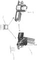
Figure 4 which shows a digital printing platform 400, such as an Indigo® available from Hewlett Packard Corporation of Palo Alto, CA. The digital printer 400 receives print instructions from acomputer 410 which may be located at the same site as the digital printer 400 or located at a remote site. Once print information is received from thecomputer 410 by the digital printer 400, the printer 400 prints substrates that will become the label, tag or tickets in which a RFID inlays may already be inserted. That is, the RFID inlays are positioned within the substrate as predetermined location so that when the sheet or web is cut, individual tags, tickets or labels are created having RFID inlays therein. The digital printer prints both variable and non-variable information as already described herein. - Still with reference to
FIGURE 4 , the feeder/encoding device 420 receives the individual RFID tags, tickets or labels and then scans the printed indicia and then encodes the individual RFID inlays as previously disclosed. Some sort of cutter (not shown), mechanical die cutter, laser cutter or the like may be included between the printer and feeder to cut the substrate, whether provided in a sheet or web form, into individual RFID tags, tickets and inlays. Information may also be received from thecomputer 410 such as verification of the EPC code to encode the RFID inlay so that it matches the indicia that was scanned from the printed portion of the substrate. The RFID tags, tickets and labels are then collected 430 in a stack to be distributed for subsequent attachment or association with consumer items such as apparel, garments, or other consumer goods. - The foregoing description and accompanying figures illustrate the principles, preferred embodiments and modes of operation of the invention. However, the invention should not be construed as being limited to the particular embodiments discussed above. Additional variations of the embodiments discussed above will be appreciated by those skilled in the art.
- Therefore, the above-described embodiments should be regarded as illustrative rather than restrictive. Accordingly, it should be appreciated that variations to those embodiments can be made by those skilled in the art without departing from the scope of the invention as defined by the following claims.
Claims (4)
- A system comprising:a digital printing platform (400) configured to:receive print instructions from a computer (410),upon receipt of the print instructions, and following this, to print indicia (30) containing variable and non-variable information on a substrate comprising a plurality of RFID inlays; said system further comprising:a cutter provided between the printer and the feeder, said cutter configured to cut the substrate into individual objects, each object comprising an RFID inlay and printed indicia (30) containing said variable and non-variable information, each of said individual objects being one of an RFID tag, RFID ticket or RFID label;said system further comprising:a feeding and encoding device (420) for receiving said individual objects and for encoding said RFID inlay (20) incorporated in said object (10), the object (10) having said printed indicia (30) disposed thereon,said feeding and encoding device (420) comprising:an object transporting mechanism (102);a scanner (104) for scanning the indicia (30);an ultraviolet illumination source (204) operatively coupled to the scanner (104) to enable the scanner to read UV-sensitive indicia;at least one RFID antenna (106) for reading and encoding the RFID inlay (20);a computing device (110) including a processor (112) in communication with and adapted to control the operation of the object transporting mechanism (102), the scanner (104), and the at least one RFID antenna (106);an object sensor (109) in communication with the processor (112),wherein the object sensor (109) is configured to detect the presence of the object (10) on the transport mechanism (102);a non-transitory computer readable medium (114) coupled to the processor (112), instructions stored on the medium (114) and executable by the processor (112), the instructions including the steps of:- receiving data read by the scanner (104);- converting the data into EPC format; and- sending the data to the at least one RFID antenna (106);wherein the RFID antenna (106) is configured to read the RFID inlay so as to verify the encoding;wherein the device (420) is configured to send an error status to software if the encoding is not successful;a sorting device configured to direct successfully encoded inlays (20) to one location, and failed inlays (20) to another location,said system further comprising a computer (410) configured to verify that the data in EPC format to be encoded on the RFID inlay matches the scanned indicia.
- The system of claim 1, wherein the object transporting mechanism (102) comprises a friction feeder and/or
wherein the first location comprises an object storage receptacle (202). - The system of claim 1, wherein the object transporting mechanism (102) is adapted to prevent interference between RFID inlays (20) of any two adjacent objects (10).
- The system of claim 1, wherein the scanner (104) is adapted to read barcodes.
Applications Claiming Priority (2)
| Application Number | Priority Date | Filing Date | Title |
|---|---|---|---|
| US13/798,786 US9613235B2 (en) | 2013-03-13 | 2013-03-13 | System, method and apparatus for encoding of RFID inlays |
| PCT/US2014/023621 WO2014159428A1 (en) | 2013-03-13 | 2014-03-11 | System, method and apparatus for encoding of rfid inlays |
Publications (2)
| Publication Number | Publication Date |
|---|---|
| EP2973233A1 EP2973233A1 (en) | 2016-01-20 |
| EP2973233B1 true EP2973233B1 (en) | 2019-05-15 |
Family
ID=50771323
Family Applications (1)
| Application Number | Title | Priority Date | Filing Date |
|---|---|---|---|
| EP14725561.6A Active EP2973233B1 (en) | 2013-03-13 | 2014-03-11 | System, method and apparatus for encoding of rfid inlays |
Country Status (5)
| Country | Link |
|---|---|
| US (1) | US9613235B2 (en) |
| EP (1) | EP2973233B1 (en) |
| CN (2) | CN115329912A (en) |
| ES (1) | ES2739801T3 (en) |
| WO (1) | WO2014159428A1 (en) |
Families Citing this family (9)
| Publication number | Priority date | Publication date | Assignee | Title |
|---|---|---|---|---|
| US20180276432A1 (en) * | 2017-03-24 | 2018-09-27 | Krishnamoorthy Manickam | System, method and apparatus for encoding, verifying, and printing of rfid enabled objects |
| US11080583B2 (en) * | 2017-09-15 | 2021-08-03 | Avery Dennison Retail Information Services, Llc | System for barcode scanning and RFID label printing |
| DE102018000628A1 (en) * | 2018-01-26 | 2019-08-01 | Mühlbauer Gmbh & Co. Kg | Apparatus and method for coding RF transponders |
| US11443160B2 (en) | 2019-09-18 | 2022-09-13 | Sensormatic Electronics, LLC | Systems and methods for laser tuning and attaching RFID tags to products |
| US10783424B1 (en) | 2019-09-18 | 2020-09-22 | Sensormatic Electronics, LLC | Systems and methods for providing tags adapted to be incorporated with or in items |
| US11055588B2 (en) | 2019-11-27 | 2021-07-06 | Sensormatic Electronics, LLC | Flexible water-resistant sensor tag |
| US11755874B2 (en) | 2021-03-03 | 2023-09-12 | Sensormatic Electronics, LLC | Methods and systems for heat applied sensor tag |
| US11869324B2 (en) | 2021-12-23 | 2024-01-09 | Sensormatic Electronics, LLC | Securing a security tag into an article |
| CN115511034A (en) * | 2022-09-09 | 2022-12-23 | 深圳市建和智能卡技术有限公司 | Method for producing double-chip ultrahigh frequency RFID electronic tag |
Citations (5)
| Publication number | Priority date | Publication date | Assignee | Title |
|---|---|---|---|---|
| EP0997837A2 (en) * | 1998-10-28 | 2000-05-03 | Hewlett-Packard Company | Integrated printing/scanning system using invisible ink for document tracking |
| US6502750B1 (en) * | 1999-11-24 | 2003-01-07 | Microscan Systems, Inc. | Scanning beam system and method for reading information symbols |
| US20030057280A1 (en) * | 2001-09-27 | 2003-03-27 | Mandile Joseph T. | Method and apparatus for rapid, serial transaction item fabrication |
| KR20110047516A (en) * | 2009-10-30 | 2011-05-09 | (주)알판트 | System for testing of RFID Card Tag and the testing method of the same |
| US20120274448A1 (en) * | 2011-04-26 | 2012-11-01 | Avery Dennison Corporation | System and Method for Automated RFID Quality Control |
Family Cites Families (11)
| Publication number | Priority date | Publication date | Assignee | Title |
|---|---|---|---|---|
| GB8628178D0 (en) * | 1986-11-25 | 1986-12-31 | Hill A R | Quantifying visual function defects |
| US6601756B2 (en) * | 2000-02-28 | 2003-08-05 | The Standard Register Company | Adhesive pattern for a mailer type business form intermediate |
| US6626361B2 (en) * | 2000-12-11 | 2003-09-30 | The Standard Register Company | Mobile automated data collection device |
| US20050116034A1 (en) * | 2003-11-28 | 2005-06-02 | Masato Satake | Printing system |
| EP1807795A1 (en) * | 2004-10-13 | 2007-07-18 | Robert Lane | Registration system |
| FR2888973B1 (en) | 2005-07-22 | 2007-10-26 | K Sa As | OPTICAL READING AND RADIOFREQUENCY ENCODING DEVICE ADAPTABLE TO PRINTER OUTPUT OF IDENTIFICATION LABELS |
| JP5148504B2 (en) * | 2005-12-09 | 2013-02-20 | テゴ,インコーポレイテッド | Multiple radio frequency network node RFID tag |
| US8988223B2 (en) * | 2005-12-09 | 2015-03-24 | Tego Inc. | RFID drive management facility |
| WO2010065870A1 (en) | 2008-12-04 | 2010-06-10 | Element Id, Inc. | Apparatus, system, and method for automated item tracking |
| US20100214080A1 (en) | 2009-02-24 | 2010-08-26 | Sensormatic Electronics Corporation | Radio frequency identification hardtag encode and feed system |
| CN102163293B (en) * | 2010-02-18 | 2014-06-04 | Ls产电株式会社 | Rfid device |
-
2013
- 2013-03-13 US US13/798,786 patent/US9613235B2/en active Active
-
2014
- 2014-03-11 CN CN202210985265.6A patent/CN115329912A/en active Pending
- 2014-03-11 EP EP14725561.6A patent/EP2973233B1/en active Active
- 2014-03-11 CN CN201480025004.3A patent/CN105164701A/en active Pending
- 2014-03-11 ES ES14725561T patent/ES2739801T3/en active Active
- 2014-03-11 WO PCT/US2014/023621 patent/WO2014159428A1/en active Application Filing
Patent Citations (5)
| Publication number | Priority date | Publication date | Assignee | Title |
|---|---|---|---|---|
| EP0997837A2 (en) * | 1998-10-28 | 2000-05-03 | Hewlett-Packard Company | Integrated printing/scanning system using invisible ink for document tracking |
| US6502750B1 (en) * | 1999-11-24 | 2003-01-07 | Microscan Systems, Inc. | Scanning beam system and method for reading information symbols |
| US20030057280A1 (en) * | 2001-09-27 | 2003-03-27 | Mandile Joseph T. | Method and apparatus for rapid, serial transaction item fabrication |
| KR20110047516A (en) * | 2009-10-30 | 2011-05-09 | (주)알판트 | System for testing of RFID Card Tag and the testing method of the same |
| US20120274448A1 (en) * | 2011-04-26 | 2012-11-01 | Avery Dennison Corporation | System and Method for Automated RFID Quality Control |
Also Published As
| Publication number | Publication date |
|---|---|
| EP2973233A1 (en) | 2016-01-20 |
| CN115329912A (en) | 2022-11-11 |
| US20140266633A1 (en) | 2014-09-18 |
| CN105164701A (en) | 2015-12-16 |
| US9613235B2 (en) | 2017-04-04 |
| WO2014159428A1 (en) | 2014-10-02 |
| ES2739801T3 (en) | 2020-02-04 |
Similar Documents
| Publication | Publication Date | Title |
|---|---|---|
| EP2973233B1 (en) | System, method and apparatus for encoding of rfid inlays | |
| EP1756759B1 (en) | Item carrying at least two data storage elements | |
| EP1859383B1 (en) | Method and system for testing rfid devices | |
| US7114654B2 (en) | RFID encoder and verifier | |
| EP2788920B1 (en) | Rfid digital print/encode | |
| EP1894137B1 (en) | System and method for machine readable symbol backup for radio frequency identification tags | |
| US20180276432A1 (en) | System, method and apparatus for encoding, verifying, and printing of rfid enabled objects | |
| CN107153866A (en) | The clothes paster label and its manufacture method of a kind of function containing RFID | |
| EP2746992A1 (en) | Method and apparatus for providing printed and encoded RFID tags | |
| US11544485B2 (en) | Device and method for coding high frequency (HF) transponders | |
| CN203739435U (en) | Ultrahigh frequency and radio frequency label printer | |
| KR20120067798A (en) | Rfid label | |
| US20220318724A1 (en) | Methods and apparatus for linking pre-printed labels to product information | |
| US8537394B2 (en) | Printer and scale with initialization process for selecting RFID frequency band for communicating with RFID labels | |
| KR20220150241A (en) | Radio frequency encoding system that enables accurate and rapid encoding by continuously supplying rf chips and performing encoding and defect inspection continuously | |
| JP2020177445A (en) | Logistics management method and logistics management system | |
| JP2004133865A (en) | Rugged character reading/recognizing inspection apparatus |
Legal Events
| Date | Code | Title | Description |
|---|---|---|---|
| PUAI | Public reference made under article 153(3) epc to a published international application that has entered the european phase |
Free format text: ORIGINAL CODE: 0009012 |
|
| 17P | Request for examination filed |
Effective date: 20151013 |
|
| AK | Designated contracting states |
Kind code of ref document: A1 Designated state(s): AL AT BE BG CH CY CZ DE DK EE ES FI FR GB GR HR HU IE IS IT LI LT LU LV MC MK MT NL NO PL PT RO RS SE SI SK SM TR |
|
| AX | Request for extension of the european patent |
Extension state: BA ME |
|
| DAX | Request for extension of the european patent (deleted) | ||
| STAA | Information on the status of an ep patent application or granted ep patent |
Free format text: STATUS: EXAMINATION IS IN PROGRESS |
|
| 17Q | First examination report despatched |
Effective date: 20170418 |
|
| GRAP | Despatch of communication of intention to grant a patent |
Free format text: ORIGINAL CODE: EPIDOSNIGR1 |
|
| STAA | Information on the status of an ep patent application or granted ep patent |
Free format text: STATUS: GRANT OF PATENT IS INTENDED |
|
| INTG | Intention to grant announced |
Effective date: 20181211 |
|
| GRAS | Grant fee paid |
Free format text: ORIGINAL CODE: EPIDOSNIGR3 |
|
| GRAA | (expected) grant |
Free format text: ORIGINAL CODE: 0009210 |
|
| STAA | Information on the status of an ep patent application or granted ep patent |
Free format text: STATUS: THE PATENT HAS BEEN GRANTED |
|
| AK | Designated contracting states |
Kind code of ref document: B1 Designated state(s): AL AT BE BG CH CY CZ DE DK EE ES FI FR GB GR HR HU IE IS IT LI LT LU LV MC MK MT NL NO PL PT RO RS SE SI SK SM TR |
|
| REG | Reference to a national code |
Ref country code: CH Ref legal event code: EP |
|
| REG | Reference to a national code |
Ref country code: DE Ref legal event code: R096 Ref document number: 602014046793 Country of ref document: DE |
|
| REG | Reference to a national code |
Ref country code: IE Ref legal event code: FG4D |
|
| REG | Reference to a national code |
Ref country code: NL Ref legal event code: MP Effective date: 20190515 |
|
| REG | Reference to a national code |
Ref country code: LT Ref legal event code: MG4D |
|
| PG25 | Lapsed in a contracting state [announced via postgrant information from national office to epo] |
Ref country code: AL Free format text: LAPSE BECAUSE OF FAILURE TO SUBMIT A TRANSLATION OF THE DESCRIPTION OR TO PAY THE FEE WITHIN THE PRESCRIBED TIME-LIMIT Effective date: 20190515 Ref country code: NL Free format text: LAPSE BECAUSE OF FAILURE TO SUBMIT A TRANSLATION OF THE DESCRIPTION OR TO PAY THE FEE WITHIN THE PRESCRIBED TIME-LIMIT Effective date: 20190515 Ref country code: PT Free format text: LAPSE BECAUSE OF FAILURE TO SUBMIT A TRANSLATION OF THE DESCRIPTION OR TO PAY THE FEE WITHIN THE PRESCRIBED TIME-LIMIT Effective date: 20190915 Ref country code: SE Free format text: LAPSE BECAUSE OF FAILURE TO SUBMIT A TRANSLATION OF THE DESCRIPTION OR TO PAY THE FEE WITHIN THE PRESCRIBED TIME-LIMIT Effective date: 20190515 Ref country code: FI Free format text: LAPSE BECAUSE OF FAILURE TO SUBMIT A TRANSLATION OF THE DESCRIPTION OR TO PAY THE FEE WITHIN THE PRESCRIBED TIME-LIMIT Effective date: 20190515 Ref country code: NO Free format text: LAPSE BECAUSE OF FAILURE TO SUBMIT A TRANSLATION OF THE DESCRIPTION OR TO PAY THE FEE WITHIN THE PRESCRIBED TIME-LIMIT Effective date: 20190815 Ref country code: LT Free format text: LAPSE BECAUSE OF FAILURE TO SUBMIT A TRANSLATION OF THE DESCRIPTION OR TO PAY THE FEE WITHIN THE PRESCRIBED TIME-LIMIT Effective date: 20190515 Ref country code: HR Free format text: LAPSE BECAUSE OF FAILURE TO SUBMIT A TRANSLATION OF THE DESCRIPTION OR TO PAY THE FEE WITHIN THE PRESCRIBED TIME-LIMIT Effective date: 20190515 |
|
| PG25 | Lapsed in a contracting state [announced via postgrant information from national office to epo] |
Ref country code: RS Free format text: LAPSE BECAUSE OF FAILURE TO SUBMIT A TRANSLATION OF THE DESCRIPTION OR TO PAY THE FEE WITHIN THE PRESCRIBED TIME-LIMIT Effective date: 20190515 Ref country code: GR Free format text: LAPSE BECAUSE OF FAILURE TO SUBMIT A TRANSLATION OF THE DESCRIPTION OR TO PAY THE FEE WITHIN THE PRESCRIBED TIME-LIMIT Effective date: 20190816 Ref country code: LV Free format text: LAPSE BECAUSE OF FAILURE TO SUBMIT A TRANSLATION OF THE DESCRIPTION OR TO PAY THE FEE WITHIN THE PRESCRIBED TIME-LIMIT Effective date: 20190515 Ref country code: BG Free format text: LAPSE BECAUSE OF FAILURE TO SUBMIT A TRANSLATION OF THE DESCRIPTION OR TO PAY THE FEE WITHIN THE PRESCRIBED TIME-LIMIT Effective date: 20190815 |
|
| REG | Reference to a national code |
Ref country code: AT Ref legal event code: MK05 Ref document number: 1134307 Country of ref document: AT Kind code of ref document: T Effective date: 20190515 |
|
| PG25 | Lapsed in a contracting state [announced via postgrant information from national office to epo] |
Ref country code: AT Free format text: LAPSE BECAUSE OF FAILURE TO SUBMIT A TRANSLATION OF THE DESCRIPTION OR TO PAY THE FEE WITHIN THE PRESCRIBED TIME-LIMIT Effective date: 20190515 Ref country code: DK Free format text: LAPSE BECAUSE OF FAILURE TO SUBMIT A TRANSLATION OF THE DESCRIPTION OR TO PAY THE FEE WITHIN THE PRESCRIBED TIME-LIMIT Effective date: 20190515 Ref country code: EE Free format text: LAPSE BECAUSE OF FAILURE TO SUBMIT A TRANSLATION OF THE DESCRIPTION OR TO PAY THE FEE WITHIN THE PRESCRIBED TIME-LIMIT Effective date: 20190515 Ref country code: RO Free format text: LAPSE BECAUSE OF FAILURE TO SUBMIT A TRANSLATION OF THE DESCRIPTION OR TO PAY THE FEE WITHIN THE PRESCRIBED TIME-LIMIT Effective date: 20190515 Ref country code: CZ Free format text: LAPSE BECAUSE OF FAILURE TO SUBMIT A TRANSLATION OF THE DESCRIPTION OR TO PAY THE FEE WITHIN THE PRESCRIBED TIME-LIMIT Effective date: 20190515 Ref country code: SK Free format text: LAPSE BECAUSE OF FAILURE TO SUBMIT A TRANSLATION OF THE DESCRIPTION OR TO PAY THE FEE WITHIN THE PRESCRIBED TIME-LIMIT Effective date: 20190515 |
|
| REG | Reference to a national code |
Ref country code: ES Ref legal event code: FG2A Ref document number: 2739801 Country of ref document: ES Kind code of ref document: T3 Effective date: 20200204 |
|
| REG | Reference to a national code |
Ref country code: DE Ref legal event code: R097 Ref document number: 602014046793 Country of ref document: DE |
|
| PG25 | Lapsed in a contracting state [announced via postgrant information from national office to epo] |
Ref country code: IT Free format text: LAPSE BECAUSE OF FAILURE TO SUBMIT A TRANSLATION OF THE DESCRIPTION OR TO PAY THE FEE WITHIN THE PRESCRIBED TIME-LIMIT Effective date: 20190515 Ref country code: SM Free format text: LAPSE BECAUSE OF FAILURE TO SUBMIT A TRANSLATION OF THE DESCRIPTION OR TO PAY THE FEE WITHIN THE PRESCRIBED TIME-LIMIT Effective date: 20190515 |
|
| PLBE | No opposition filed within time limit |
Free format text: ORIGINAL CODE: 0009261 |
|
| STAA | Information on the status of an ep patent application or granted ep patent |
Free format text: STATUS: NO OPPOSITION FILED WITHIN TIME LIMIT |
|
| PG25 | Lapsed in a contracting state [announced via postgrant information from national office to epo] |
Ref country code: TR Free format text: LAPSE BECAUSE OF FAILURE TO SUBMIT A TRANSLATION OF THE DESCRIPTION OR TO PAY THE FEE WITHIN THE PRESCRIBED TIME-LIMIT Effective date: 20190515 |
|
| 26N | No opposition filed |
Effective date: 20200218 |
|
| PG25 | Lapsed in a contracting state [announced via postgrant information from national office to epo] |
Ref country code: PL Free format text: LAPSE BECAUSE OF FAILURE TO SUBMIT A TRANSLATION OF THE DESCRIPTION OR TO PAY THE FEE WITHIN THE PRESCRIBED TIME-LIMIT Effective date: 20190515 |
|
| PG25 | Lapsed in a contracting state [announced via postgrant information from national office to epo] |
Ref country code: SI Free format text: LAPSE BECAUSE OF FAILURE TO SUBMIT A TRANSLATION OF THE DESCRIPTION OR TO PAY THE FEE WITHIN THE PRESCRIBED TIME-LIMIT Effective date: 20190515 |
|
| PG25 | Lapsed in a contracting state [announced via postgrant information from national office to epo] |
Ref country code: MC Free format text: LAPSE BECAUSE OF FAILURE TO SUBMIT A TRANSLATION OF THE DESCRIPTION OR TO PAY THE FEE WITHIN THE PRESCRIBED TIME-LIMIT Effective date: 20190515 |
|
| REG | Reference to a national code |
Ref country code: CH Ref legal event code: PL |
|
| REG | Reference to a national code |
Ref country code: BE Ref legal event code: MM Effective date: 20200331 |
|
| PG25 | Lapsed in a contracting state [announced via postgrant information from national office to epo] |
Ref country code: LU Free format text: LAPSE BECAUSE OF NON-PAYMENT OF DUE FEES Effective date: 20200311 |
|
| PG25 | Lapsed in a contracting state [announced via postgrant information from national office to epo] |
Ref country code: LI Free format text: LAPSE BECAUSE OF NON-PAYMENT OF DUE FEES Effective date: 20200331 Ref country code: CH Free format text: LAPSE BECAUSE OF NON-PAYMENT OF DUE FEES Effective date: 20200331 Ref country code: IE Free format text: LAPSE BECAUSE OF NON-PAYMENT OF DUE FEES Effective date: 20200311 |
|
| PG25 | Lapsed in a contracting state [announced via postgrant information from national office to epo] |
Ref country code: BE Free format text: LAPSE BECAUSE OF NON-PAYMENT OF DUE FEES Effective date: 20200331 |
|
| PG25 | Lapsed in a contracting state [announced via postgrant information from national office to epo] |
Ref country code: MT Free format text: LAPSE BECAUSE OF FAILURE TO SUBMIT A TRANSLATION OF THE DESCRIPTION OR TO PAY THE FEE WITHIN THE PRESCRIBED TIME-LIMIT Effective date: 20190515 Ref country code: CY Free format text: LAPSE BECAUSE OF FAILURE TO SUBMIT A TRANSLATION OF THE DESCRIPTION OR TO PAY THE FEE WITHIN THE PRESCRIBED TIME-LIMIT Effective date: 20190515 |
|
| PG25 | Lapsed in a contracting state [announced via postgrant information from national office to epo] |
Ref country code: MK Free format text: LAPSE BECAUSE OF FAILURE TO SUBMIT A TRANSLATION OF THE DESCRIPTION OR TO PAY THE FEE WITHIN THE PRESCRIBED TIME-LIMIT Effective date: 20190515 Ref country code: IS Free format text: LAPSE BECAUSE OF FAILURE TO SUBMIT A TRANSLATION OF THE DESCRIPTION OR TO PAY THE FEE WITHIN THE PRESCRIBED TIME-LIMIT Effective date: 20190915 |
|
| REG | Reference to a national code |
Ref country code: ES Ref legal event code: PC2A Owner name: AVERY DENNISON RETAIL INFORMATION SERVICES LLC Effective date: 20220630 Ref country code: GB Ref legal event code: 732E Free format text: REGISTERED BETWEEN 20220609 AND 20220615 |
|
| REG | Reference to a national code |
Ref country code: DE Ref legal event code: R081 Ref document number: 602014046793 Country of ref document: DE Owner name: AVERY DENNISON RETAIL INFORMATION SERVICES LLC, US Free format text: FORMER OWNER: AVERY DENNISON CORP., MENTOR, OH, US |
|
| REG | Reference to a national code |
Ref country code: DE Ref legal event code: R081 Ref document number: 602014046793 Country of ref document: DE Owner name: AVERY DENNISON RETAIL INFORMATION SERVICES LLC, US Free format text: FORMER OWNER: AVERY DENNISON RETAIL INFORMATION SERVICES, LLC, MENTOR, OH, US Ref country code: DE Ref legal event code: R081 Ref document number: 602014046793 Country of ref document: DE Owner name: AVERY DENNISON RETAIL INFORMATION SERVICES LLC, US Free format text: FORMER OWNER: AVERY DENNISON RETAIL INFORMATION SERVICES LLC, MENTOR, OH, US |
|
| PGFP | Annual fee paid to national office [announced via postgrant information from national office to epo] |
Ref country code: FR Payment date: 20230209 Year of fee payment: 10 |
|
| PGFP | Annual fee paid to national office [announced via postgrant information from national office to epo] |
Ref country code: GB Payment date: 20230208 Year of fee payment: 10 Ref country code: DE Payment date: 20230210 Year of fee payment: 10 |
|
| PGFP | Annual fee paid to national office [announced via postgrant information from national office to epo] |
Ref country code: ES Payment date: 20230403 Year of fee payment: 10 |