EP2972950B1 - Segmentation of content delivery - Google Patents
Segmentation of content delivery Download PDFInfo
- Publication number
- EP2972950B1 EP2972950B1 EP14769352.7A EP14769352A EP2972950B1 EP 2972950 B1 EP2972950 B1 EP 2972950B1 EP 14769352 A EP14769352 A EP 14769352A EP 2972950 B1 EP2972950 B1 EP 2972950B1
- Authority
- EP
- European Patent Office
- Prior art keywords
- segment
- virtual object
- dimensional model
- physical object
- delivery
- Prior art date
- Legal status (The legal status is an assumption and is not a legal conclusion. Google has not performed a legal analysis and makes no representation as to the accuracy of the status listed.)
- Not-in-force
Links
Images


Classifications
-
- G—PHYSICS
- G06—COMPUTING; CALCULATING OR COUNTING
- G06T—IMAGE DATA PROCESSING OR GENERATION, IN GENERAL
- G06T15/00—3D [Three Dimensional] image rendering
- G06T15/10—Geometric effects
- G06T15/20—Perspective computation
-
- G—PHYSICS
- G06—COMPUTING; CALCULATING OR COUNTING
- G06T—IMAGE DATA PROCESSING OR GENERATION, IN GENERAL
- G06T2200/00—Indexing scheme for image data processing or generation, in general
- G06T2200/16—Indexing scheme for image data processing or generation, in general involving adaptation to the client's capabilities
Description
- The subject matter disclosed herein generally relates to the processing of data. Specifically, the present disclosure addresses systems and methods for segmentation of content delivery.
- A device can be used to generate data based on an image captured with the device. For example, augmented reality (AR) is a live, direct or indirect, view of a physical, real- world environment whose elements are augmented by computer-generated sensory input such as sound, video, graphics or GPS data. With the help of advanced AR technology (e.g. adding computer vision and object recognition) the information about the surrounding real world of the user becomes interactive. Artificial information about the environment and its objects can be overlaid on the real world. The artificial information may include large amounts of data that may cause delay for a user of a device to view the artificial information.
- Distributed Visual Processing for Augmented Reality, Winston Yii et al 2012 IEEE (ISBN 978-1-4673-4660-3) relates to augmented reality based on a process of matching techniques in which key-points (e.g. corners of a box) are extracted from a frame taken by a smartphone camera. Captured images are converted to greyscale and the greyscale image is down-sampled before corners are extracted. For each corner a descriptor is built and the key-points and their descriptors are sent to a server for processing. The feature is sampled according to concentric Bresenham circles of varying radii and the sampled pixel intensities are normalised for variance and mean before quantising each pixel's normalised intensity into one of four bins. The pixels are sampled in an order of radial sectors moving around a circle. This symmetry improves the matching technique under different rotations of the smartphone camera since the key-point descriptors of the virtual object are more efficiently matched to those of the down-sampled frames. The reference descriptors are sorted by bit count and starting with the lowest bit count a preferred "partner" for that descriptor is found. As such, pose or orientation is solved iteratively from an initial assumption that the smartphone camera and virtual object frames are coincident. After processing, virtual object locations are then sent back to the smartphone based on the initial key-points and descriptors.
-
US 8,335,348 B2 relates to a method of tracking an object. It describes dividing an object into a plurality of object segments. A number and size of the object segments are configurable and may be specified by the user of the system. -
US 7,933,228 B2 relates to a time sensitive scheduling data delivery network. Scheduling streams are created from aggregating time sensitive scheduling data from multiple originating organisations. These may be based on desirability and relevance for a particular entity where the entity's interests are derived from information in their membership rolls. - The invention is defined by the independent claims. Preferred embodiments are defined by the dependent claims.
- Some embodiments are illustrated by way of example and not limitation in the figures of the accompanying drawings.
-
FIG. 1 is a block diagram illustrating an example of a network suitable for operating a campaign optimizer, according to some example embodiments. -
FIG. 2 is a block diagram illustrating modules (e.g., components) of a server, according to some example embodiments. -
FIG. 3 is a block diagram illustrating modules (e.g., components) of a delivery segmentation module, according to some example embodiments. -
FIG. 4 is a block diagram illustrating an example of an operation of the delivery segmentation module, according to some example embodiments. -
FIG. 5 is a block diagram illustrating an example of an operation of the analytics computation, according to some example embodiments. -
FIG. 6 is a block diagram illustrating modules (e.g., components) of a device, according to some example embodiments. -
FIG. 7 is a block diagram illustrating modules (e.g., components) of the analytics tracking module, according to some example embodiments. -
FIG. 8A is a block diagram illustrating an example of an operation of the delivery segmentation module of a virtual object, according to some example embodiments. -
FIG. 8B is a block diagram illustrating an example of an operation of the delivery segmentation module of several virtual objects, according to some example embodiments. -
FIG. 9 is a schematic diagram illustrating an example of a flow process for segmentation of content delivery, according to some example embodiments. -
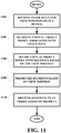
FIG. 10 is a flowchart illustrating an example method for segmentation of content delivery, according to some example embodiments. -
FIG. 11 is a flowchart illustrating another example method for segmentation of content delivery, according to some example embodiments. -
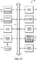
FIG. 12 is a block diagram illustrating components of a machine, according to some example embodiments, able to read instructions from a machine-readable medium and perform any one or more of the methodologies discussed herein. - Example methods and systems are directed to segmentation of content delivery. Examples merely typify possible variations. Unless explicitly stated otherwise, components and functions are optional and may be combined or subdivided, and operations may vary in sequence or be combined or subdivided. In the following description, for purposes of explanation, numerous specific details are set forth to provide a thorough understanding of example embodiments. It will be evident to one skilled in the art, however, that the present subject matter may be practiced without these specific details.
- A server for segmentation of content delivery is described. A virtual object model is divided into a plurality of segments. An order of the plurality of segments is arranged in a delivery queue. Each segment of the virtual object model is delivered in the order of the delivery queue to a device that is configured to recognize a physical object that is associated with the virtual object model.
- Augmented reality applications allow a user to experience additional information, such as in the form of a virtual object overlaid on a realtime picture of a physical object captured by a camera of a device. The physical object may include a visual reference (also referred to as a content identifier) that the augmented reality application can identify and recognized. A visualization of the virtual object overlaid on the real-time picture of the physical object is generated in a display of the device. The virtual object may be based on the recognized visual reference. A rendering of the visualization of the virtual object is based on a position and an orientation of the display relative to the visual reference and the physical object.
- In a first aspect, the server includes a memory configured to store a three-dimensional model of a virtual object, and a hardware processor implemented by a delivery segmentation module configured to divide the three-dimensional model into a plurality of segments, each segment of the three-dimensional model corresponding to a part of the virtual object, determine a position and an orientation of a device in relation to a physical object, divide the three-dimensional model into a first and a second segment of the plurality of segments based on the position and the orientation of the device in relation to the physical object, the first segment including parts of the virtual object visible from the device, the second segment including parts of the virtual object not visible from the device, generate analytics results based on analytics data received from a plurality of devices, the analytics results identifying a rate at which each feature of the three-dimensional model is interacted with and a rate at which each location on the three-dimensional model is viewed by the plurality of devices, divide the three-dimensional model into a third and a fourth segment of the plurality of segments based on the analytics results, a feature included in the third segment being interacted with most often, a location corresponding to the third segment being viewed most often, arrange an order of the plurality of segments in a delivery queue based on the analytics results and based on the position and the orientation of the device in relation to the physical object, the first segment being queued before the second segment in the delivery queue, the third segment being queued before the fourth segment in the delivery queue, and deliver each segment in accordance with the order of the delivery queue to the device that is configured to recognize the physical object that is associated with the three-dimensional model of the virtual object.
- In one embodiment, the delivery segmentation module is configured to determine a fifth segment corresponding to a first externally visible surface part of the virtual object, determine a sixth segment corresponding to a second externally visible surface part of the virtual object, determine that the fifth segment is in a line of sight between the device and the sixth segment, and deliver the fifth segment to the device prior to the sixth segment, the sixth segment rendered at the device after the fifth segment is rendered at the device.
- In one embodiment, the delivery segmentation module is configured to determine a fifth segment corresponding to a part of a first virtual object, and determine a sixth segment corresponding to a part of a second virtual object, determine that the fifth segment is in a line of sight between the device and the sixth segment, and deliver the fifth segment to the device prior to the sixth segment, the sixth segment rendered at the device after the fifth segment is rendered at the device.
- In one embodiment, the delivery segmentation moduleis configured to receive pose estimation data of the device relative to the physical object captured with the device, pose duration data of the device relative to the physical object captured with the device, pose orientation data of the device relative to the physical object captured with the device, and pose interaction data of the device relative to the physical object captured with the device.
- In a second aspect, there is provided a computer-implemented method comprising dividing a three-dimensional model of a virtual object into a plurality of segments, each segment of the three-dimensional model corresponding to a part of the virtual object, determining a position and an orientation of a device in relation to a physical object, dividing the three-dimensional model into a first and a second segment of the plurality of segments based on the position and the orientation of the device in relation to the physical object, the first segment including parts of the virtual object visible from the device, the second segment including parts of the virtual object not visible from the device, generating analytics results based on analytics data received from a plurality of devices, the analytics results identifying a rate at which each feature of the three-dimensional model is interacted with and a rate at which each location on the three-dimensional model is viewed by the plurality of devices, dividing the three-dimensional model into a third and a fourth segment of the plurality of segments based on the analytics results, a feature corresponding to the third segment being operated on most often, a location corresponding to the third segment being viewed most often, arranging an order of the plurality of segments in a delivery queue based on the analytics results and based on the position and the orientation of the device in relation to the physical object, the first segment being queued before the second segment in the delivery queue, the third segment being queued before the fourth segment in the delivery queue, and delivering each segment in accordance with the order of the delivery queue to the device that is configured to recognize the physical object that is associated with the three-dimensional model of the virtual object.
- The computer-implemented method may further comprise determining a fifth segment corresponding to a first externally visible surface part of the virtual object, determining a sixth segment corresponding to a second externally visible surface part of the virtual object, determining that the fifth segment is in a line of sight between the device and the sixth segment, and delivering the fifth segment to the device prior to the sixth segment, the sixth segment rendered at the device after the fifth segment is rendered at the device.
- The computer-implemented method may further comprise determining a fifth segment corresponding to a part of a first virtual object, determining a sixth segment corresponding to a part of a second virtual object, determining that the fifth segment is in a line of sight between the device and the sixth segment, and delivering the fiftth segment to the device prior to the sixth segment, the sixth segment rendered at the device after the fifth segment is rendered at the device.
- In a third aspect, there is provided a non-transitory machine-readable storage medium comprising instructions that, when executed by one or more processors of a machine, cause the machine to perform operations comprising dividing a three-dimensional model of a virtual object into a plurality of segments, each segment of the three-dimensional model corresponding to a part of the virtual object, determining a position and an orientation of a device in relation to a physical object, dividing the three-dimensional model into a first and a second segment of the plurality of segments based on the position and the orientation of the device in relation to the physical object, the first segment including parts of the virtual object visible from the device, the second segment including parts of the virtual object not visible from the device, generating analytics results based on analytics data received from a plurality of devices, the analytics results identifying a rate at which each feature of the three-dimensional model is interacted with and a rate at which each location on the three-dimensional model is viewed by the plurality of devices, dividing the three-dimensional model into a third and a fourth segment of the plurality of segments based on the analytics results, a feature corresponding to the third segment being operated on most often, a location corresponding to the third segment being viewed most often, arranging an order of the plurality of segments in a delivery queue based on the analytics results and based on the position and the orientation of the device in relation to the physical object, the first segment being queued before the second segment in the delivery queue, the third segment being queued before the fourth segment in the delivery queue, and delivering each segment in accordance with the order of the delivery queue to the device that is configured to recognize the physical object that is associated with the three-dimensional model of the virtual object.
-
FIG. 1 is a network diagram illustrating anetwork environment 100 suitable for operating an augmented reality application of a device, according to some example embodiments. Thenetwork environment 100 includes adevice 101, aclient 112, and aserver 110, communicatively coupled to each other via anetwork 108. Thedevice 101, theclient 112, and theserver 110 may each be implemented in a computer system, in whole or in part, as described below with respect toFIG.12 . - The
server 110 may be part of a network-based system. For example, the network-based system may be or includes a cloud-based server system that provides campaign optimization for an experience content dataset. Theclient 112 may access theserver 110 via a web-browser or a programmatic client to prepare content for delivery at thedevice 101. - A
user 102 may use thedevice 101 to experience (e.g., operate, view, or play) an interactive content generated by a content dataset generated by theserver 110. In one example, theuser 102 may use theclient 112 to use a content creation tool of theserver 110 to generate the interactive content on thedevice 101. The user may be a human user (e.g., a human being), a machine user (e.g., a computer configured by a software program to interact with the device 101), or any suitable combination thereof (e.g., a human assisted by a machine or a machine supervised by a human). Theuser 102 is not part of thenetwork environment 100, but is associated with thedevice 101 and may be a user of thedevice 101. For example, thedevice 101 may be a desktop computer, a vehicle computer, a tablet computer, a navigational device, a portable media device, or a smart phone belonging to theuser 102. - In another example,
user 102 may be a user of an application in thedevice 101. The application may include an augmented reality application configured to provide theuser 102 with virtual information displayed on a top of image of a physical object captured in real time. The physical object may be for example, a two-dimensional physical object 104 (e.g., a picture) or a three-dimensional physical object 106 (e.g., a car or a building). For example, theuser 102 may point thedevice 101 to capture an image of the two-dimensionalphysical object 104. The image is recognized locally in thedevice 101 using a local context recognition dataset module that contains a library of virtual object models and corresponding images. The augmented reality application then generates information (e.g., an interactive three-dimensional virtual object) in a display of thedevice 101 in response to identifying the recognized image. If the capture image is not recognized locally at thedevice 101, thedevice 101 may request for the three-dimensional model corresponding to the captured image, from a database of theserver 110 over thenetwork 108. - The
device 101 may capture and submit analytics data to theserver 110 for further analysis on usage and how theuser 102 is engaged with the physical object. For example, the analytics data may include a location where the user looked at on the physical or virtual object, a length of time theuser 102 has looked at each location on the physical or virtual object, how theuser 102 held thedevice 101 when looking at the physical or virtual object, which features of the virtual object theuser 102 interacted with (e.g., such as whether a user tapped on a link in the virtual object). The analytics data may be processed at theserver 110 to generate another content dataset. Thedevice 101 may receive and generate a virtual object with additional or enhanced features or a new experience based on the new content dataset. - Any of the machines, databases, or devices shown in
FIG. 1 may be implemented in a general-purpose computer modified (e.g., configured or programmed) by software to be a special-purpose computer to perform one or more of the functions described herein for that machine, database, or device. For example, a computer system able to implement any one or more of the methodologies described herein is discussed below with respect toFIG. 12 . As used herein, a "database" is a data storage resource and may store data structured as a text file, a table, a spreadsheet, a relational database (e.g., an object-relational database), a triple store, a hierarchical data store, or any suitable combination thereof. Moreover, any two or more of the machines, databases, or devices illustrated inFIG. 1 may be combined into a single machine, and the functions described herein for any single machine, database, or device may be subdivided among multiple machines, databases, or devices. - The
network 108 may be any network that enables communication between or among machines (e.g., server 110), databases, and devices (e.g., device 101). Accordingly, thenetwork 108 may be a wired network, a wireless network (e.g., a mobile or cellular network), or any suitable combination thereof. Thenetwork 108 may include one or more portions that constitute a private network, a public network (e.g., the Internet), or any suitable combination thereof. -
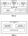
FIG. 2 is a block diagram illustrating modules (e.g., components) of theserver 110, according to some example embodiments. Theserver 110 includes adelivery segmentation module 202, anexperience generator 204, ananalytics computation module 206, and adatabase 208. - The
delivery segmentation module 202 may divide a virtual object model into several portions or segments. The segments are arranged in a delivery queue so that each segment may be asynchronously delivered thedevice 101. In other words, one segment of the virtual object model may be delivered before another segment of the virtual object model. Thedelivery segmentation module 202 is described in more details below with respect toFIG. 3 . - The
experience generator 204 may provide the content dataset to thedevice 101 that recognizes the content identifier, and generate an interactive experience with the virtual object content at thedevice 101. In one embodiment, theexperience generator 204 generate a virtual object model using the content dataset to be rendered in a display of thedevice 101 based on a position of thedevice 101 relative to a physical object such as the two-dimensional physical object 104 (e.g., a picture) or the three-dimensional physical object 106 (e.g., a car). Thedevice 101 recognizes the two-dimensional physical object 104 (e.g., a picture) or the three-dimensional physical object 106 (e.g., a car) as the content identifier. The visualization of the virtual object may correspond to the virtual object model overlaid on top of a real-time image of the physical object captured with thedevice 101. The virtual object model may be determined by an image of the physical object. - The
analytics computation module 206 may operate on analytics data received from thedevice 101 or other devices to generate analytics results. In one embodiment, theanalytics computation module 206 analyzes a pose estimation of thedevice 101 relative to the physical object captured with thedevice 101, a pose duration of thedevice 101 relative to the physical object captured with thedevice 101, a pose orientation of the device relative to the physical object captured with thedevice 101, and a pose interaction of the device relative to the physical object captured with thedevice 101. The pose estimation may include a location on the physical or virtual object aimed by thedevice 101. The pose duration may include a time duration within which thedevice 101 is aimed at a same location on the physical or virtual object. The pose orientation may include an orientation and a position of thedevice 101 aimed at the physical or virtual object. The pose interaction may include interactions of the user on thedevice 101 with respect the virtual object corresponding to the physical object. - The
database 208 may includecontent dataset 212, and analytics and resultsdata 214. Thecontent dataset 212 may include datasets generated based on content creation template data using a content creation tool. For example, the datasets may include a library or a table of interactive virtual contents (e.g., virtual object models) and corresponding images of physical contents. - The analytics and
results data 214 may include analytics data received from devices. For example, the analytics data may include pose estimation data, pose duration data, pose orientation data, pose interaction data, sentiment data, among others. The analytics andresults data 214 may include results data from an analysis of the analytics data generated by theanalytics computation module 206. Results data may include, for example, most often used features, most often looked at location of a virtual content from thecontent dataset 212. -
FIG. 3 is a block diagram illustrating modules (e.g., components) of thedelivery segmentation module 202, according to some example embodiments. Thedelivery segmentation module 202 includes an analytics-basedsegmentation module 302, a view-basedsegmentation module 304, and asegment delivery module 306. - In one embodiment, the analytics-based
segmentation module 302 may access the analytics results, and may divide the virtual object model into segments based on the analytics results. Thesegment delivery module 306 may deliver the segments in an order based on the analytics results. - In one embodiment, the view-based
segmentation module 304 determines the position and the orientation of thedevice 101 in relation to thephysical object segmentation module 304 divides the virtual object model into segments based on the position and the orientation of thedevice 101 in relation to thephysical object segment delivery module 306 may deliver the segments in an order based on the position and the orientation of thedevice 101 in relation to thephysical object - In another embodiment, the view-based
segmentation module 304 may determine that a first segment corresponds to a first virtual object of the virtual object model. The first virtual object may be exposed in a view based on the position and the orientation of thedevice 101 in relation to thephysical object segmentation module 304 may determine that a second segment correspond to a second virtual object of the virtual object model. The second virtual object may be hidden from view by the first virtual object based on the position and the orientation of the device in relation to the physical object. Thesegment delivery module 306 may deliver the first segment before to the second segment to thedevice 101. -
FIG. 4 is a block diagram illustrating an example of an operation of thedelivery segmentation module 202, according to some example embodiments. The analytics-basedsegmentation module 302 of thedelivery segmentation module 202 receivesanalytics data 402, analytics results 404, and avirtual object model 408 that correspond to an image of the physical object being recognized by theserver 110 or thedevice 101. The image of the physical object may be recognized by theserver 110 if a hash of the image of the physical object matches a hash of an image in thecontent dataset 212 of theserver 110. The image of the physical object may be recognized by thedevice 101 if a hash of the image of the physical object matches a hash of an image in a content dataset of theserver device 101. - The view-based
segmentation module 304 of thedelivery segmentation module 202 receivesviewing position data 406 comprising the position and the orientation of thedevice 101 in relation to the physical object, and avirtual object model 408 that correspond to an image of the physical object being recognized by theserver 110 or thedevice 101. - The
segment delivery module 306 may deliver the segments in an order based on either the analytics-basedsegmentation module 302 or the view-basedsegmentation module 304. As such, in one embodiment, the order in which the segments are delivered or sent from theserver 110 may be based on analytics data and results 214. For example, thesegment delivery module 306 may first deliver or generate segment A, then segment B, then segment C using analytics-basedsegmentation module 302. In another embodiment, the order in which the segments are delivered or sent from theserver 110 may be based on an orientation or position of thedevice 101 viewing the physical object. For example, thesegment delivery module 306 may first deliver or generate segment B, then segment C, then segment A using view-basedsegmentation module 304. -
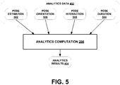
FIG. 5 is a block diagram illustrating an example of an operation of theanalytics computation module 206, according to some example embodiments. Theanalytics computation module 206 operates onanalytics data 402. In one embodiment,analytics data 402 includepose estimation data 502, poseduration data 508, poseorientation data 506, and poseinteraction data 508. - Pose
estimation data 502 may include the location on a virtual object or physical object thedevice 101 is aiming at. For example, thedevice 101 may aim at the top of a virtual statue generated by aiming thedevice 101 at thephysical object 104. In another example, thedevice 101 may aim at the shoes of a person in a picture of a magazine. - Pose
duration data 504 may include a time duration within which thedevice 101 is aimed at a same location on the physical or virtual object. For example, poseduration data 504 may include the length of the time theuser 102 has aimed and maintained the device at the shoes of a person in the magazine. User sentiment and interest of the shoes may be inferred based on the length of the time theuser 102 has held thedevice 101 aimed at the shoes. - Pose
orientation data 506 may be configured to determine an orientation of the device aimed at the physical or virtual object. For example, thepose orientation module 506 may determine that theuser 102 is holding thedevice 101 in a landscape mode and thus may infer a sentiment or interest based on the orientation of thedevice 101. - Pose
interaction data 508 may include data on interactions of theuser 102 on thedevice 101 with respect the virtual object corresponding to the physical object. For example, the virtual object may include features such as virtual menus or button. When theuser 102 taps on the virtual button, a browser application in thedevice 101 is launched to a preselected website associated with the tapped virtual dialog box. Poseinteraction data 508 may include data measuring and determining which button theuser 102 has tapped on, how often theuser 102 has tapped on which button, the click through rate for each virtual buttons, websites visited by theuser 102 from an augmented application, and so forth. - The
analytics computation module 206 analyzes the data submitted to determine patterns, trends using statistical algorithms. For example, theanalytics computation module 206 may determine features most used or clicked on, colors of virtual object clicked on the most or least, areas of the virtual object viewed the most, and so forth. The resulting computation of theanalytics computation module 206 may be referred to as analytics results 404. -
FIG. 6 is a block diagram illustrating modules (e.g., components) of thedevice 101, according to some example embodiments. Thedevice 101 may includesensors 602, adisplay 604, aprocessor 606, and astorage device 616. For example, thedevice 101 may be a desktop computer, a vehicle computer, a tablet computer, a navigational device, a portable media device, or a smart phone of a user. The user may be a human user (e.g., a human being), a machine user (e.g., a computer configured by a software program to interact with the device 101), or any suitable combination thereof (e.g., a human assisted by a machine or a machine supervised by a human). - The
sensors 602 may include, for example, a proximity sensor, an optical sensor (e.g., charged-coupled device (CCD)), an orientation sensor (e.g., gyroscope), an audio sensor (e.g., a microphone). For example, thesensors 602 may include a rear facing camera and a front facing camera in thedevice 101. It is noted that the sensors described herein are for illustration purposes and thesensors 602 are thus not limited to the ones described. - The
display 604 may include, for example, a touchscreen display configured to receive a user input via a contact on the touchscreen display. In another example, thedisplay 604 may include a screen or monitor configured to display images generated by theprocessor 606. - The
processor 606 may include anaugmented reality application 608, asegment processor 610, and ananalytics tracking module 612. - The
augmented reality application 608 may generate a visualization of a three-dimensional virtual object overlaid on top an image of a physical object captured by thedevice 101 in thedisplay 604 of thedevice 101. A visualization of the three-dimensional virtual object may be manipulated by adjusting a position of the physical object relative to the camera of thedevice 101. Similarly, the visualization of the three-dimensional virtual object may be manipulated by adjusting a position of thedevice 101 relative to the physical object. - In one embodiment, the
augmented reality application 608 communicates with thecontent dataset 616 in thedevice storage device 614 to retrieve three-dimensional models of virtual objects associated with a captured image. For example, the captured image may include a visual reference (also referred to as a marker) that consists of an identifiable image, symbol, letter, number, machine-readable code. For example, the visual reference may include a bar code, a QR code, or an image that has been previously associated with a three-dimensional virtual object. - In one embodiment, the
segment processor 610 receives segments from theserver 110 and renders a portion of a virtual object with each segment as they are received at the device. The segments receives from theserver 110 may be stored locally invirtual object segment 618 of thestorage device 614. Once all segments of a virtual object are received, the virtual object model is transferred and stored in thecontent dataset 616. - The
analytics tracking module 612 may track analytics data related to how theuser 102 is engaged with the physical object. For example, theanalytics tracking module 612 may track where on the physical or virtual object theuser 102 has looked at, how long theuser 102 has looked at each location on the physical or virtual object, how theuser 102 held thedevice 101 when looking at the physical or virtual object, which features of the virtual object theuser 102 interacted with (e.g., such as whether a user tapped on a link in the virtual object). - The
storage device 614 may be configured to store a database of visual references (e.g., images) and corresponding virtual object model (e.g., three-dimensional virtual objects, interactive features of the three-dimensional virtual objects) in acontent dataset 616. For example, the visual reference may include a machine-readable code or a previously identified image (e.g., a picture of shoe). The previously identified image of the shoe may correspond to a three-dimensional virtual model of the shoe that can be viewed from different angles by manipulating the position of thedevice 101 relative to the picture of the shoe. Features of the three-dimensional virtual shoe may include selectable icons on the three-dimensional virtual model of the shoe. An icon may be selected or activated by tapping or moving on thedevice 101. - In one embodiment, the
storage device 614 includes thecontent dataset 616, thevirtual object segment 618, andanalytics data 620. - The
content dataset 610 includes, for example, a set of images and corresponding content experiences (e.g., interactive three-dimensional virtual object models). Thecontent dataset 610 may include a core set of images or the most popular images determined by theserver 110. The core set of images may include a limited number of images identified by theserver 110. For example, the core set of images may include the cover image of the ten most popular magazines and the corresponding experiences (e.g., virtual objects). In another example, theserver 110 may generate the first set of images based on the most popular or often scanned images received at theserver 110. - The
content dataset 616 may also include, for example, a second set of images and corresponding experiences (e.g., three-dimensional virtual object models) retrieved from theserver 110. For example, images captured with thedevice 101 that are not recognized in the core set of images are submitted to theserver 110 for recognition. If the captured image is recognized by the server, a corresponding experience may be downloaded at thedevice 101 and stored in thecontent dataset 616. - The
analytics data 620 corresponds to analytics data collected by theanalytics tracking module 612. - In one embodiment, the
device 101 may communicate over thenetwork 108 with theserver 110 to retrieve a portion of a database of visual references, corresponding three-dimensional virtual objects, and corresponding interactive features of the three-dimensional virtual objects. Thenetwork 108 may be any network that enables communication between or among machines, databases, and devices (e.g., the device 101). Accordingly, thenetwork 108 may be a wired network, a wireless network (e.g., a mobile or cellular network), or any suitable combination thereof. The network may include one or more portions that constitute a private network, a public network (e.g., the Internet), or any suitable combination thereof. - Any one or more of the modules described herein may be implemented using hardware (e.g., a processor of a machine) or a combination of hardware and software. For example, any module described herein may configure a processor to perform the operations described herein for that module. Moreover, any two or more of these modules may be combined into a single module, and the functions described herein for a single module may be subdivided among multiple modules. Furthermore, according to various example embodiments, modules described herein as being implemented within a single machine, database, or device may be distributed across multiple machines, databases, or devices.
-
FIG. 7 is a block diagram illustrating modules (e.g., components) of the analytics tracking module 718, according to some example embodiments. The analytics tracking module 718 includes apose estimation module 702, apose duration module 704, apose orientation module 706, and apose interaction module 708. - The
pose estimation module 702 may be configured to detect the location on a virtual object or physical object thedevice 101 is aiming at. For example, thedevice 101 may aim at the top of a virtual statue generated by aiming thedevice 101 at thephysical object 104. In another example, thedevice 101 may aim at the shoes of a person in a picture of a magazine. - The
pose duration module 704 may be configured to determine a time duration within which thedevice 101 is aimed at a same location on the physical or virtual object. For example, thepose duration module 704 may measure the length of the time theuser 102 has aimed and maintained the device at the shoes of a person in the magazine. Sentiment and interest of the shoes may be inferred based on the length of the time theuser 102 has held thedevice 101 aimed at the shoes. - The
pose orientation module 706 may be configured to determine an orientation of the device aimed at the physical or virtual object. For example, thepose orientation module 706 may determine that theuser 102 is holding thedevice 101 in a landscape mode and thus may infer a sentiment or interest based on the orientation of thedevice 101. - The
pose interaction module 708 may be configured to determine interactions of theuser 102 on thedevice 101 with respect the virtual object corresponding to the physical object. For example, the virtual object may include features such as virtual menus or button. When theuser 102 taps on the virtual button, a browser application in thedevice 101 is launched to a preselected website associated with the tapped virtual dialog box. Thepose interaction module 708 may measure and determine which buttons theuser 102 has tapped on, the click through rate for each virtual buttons, websites visited by theuser 102 from the augmentedreality application 608, and so forth. -
FIG. 8A is a block diagram illustrating an example of an operation of the delivery segmentation module of avirtual object 810, according to some example embodiments. Thedevice 101 receives segment A prior to segment B. In this example, segment A corresponds to an exposedportion 802 of thevirtual object 810 based on the location ofdevice 101. Segment B corresponds to a hidden (non-exposed)portion 804 based on the location ofdevice 101. As such,device 101 first renders the exposedportion 802 of thevirtual object 810 by processing segment A prior to segment B. -
FIG. 8B is a block diagram illustrating an example of an operation of the delivery segmentation module of several virtual objects, according to some example embodiments.Virtual object 806 blocks a view ofvirtual object 808. As such, thedevice 101 first receives and processes segment C to rendervirtual object 806 before processing segment D to rendervirtual object 808. -
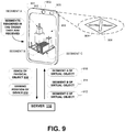
FIG. 9 is a schematic diagram illustrating an example of consuming an experience, according to some example embodiments. Thedevice 901 may be pointed at aphysical object 904 having apicture 906 that is recognized by thedevice 901. Thedevice 901 submits a hash of theimage 908 along with viewing position and orientation data of thedevice 910 to theserver 110. The viewing position and orientation relative to thephysical object 904 may be determined based on the position and orientation of thepicture 906. - The
delivery segmentation 202 of theserver 110 divides avirtual object model 908 associated with thepicture 906 into several segments: segment A, B, and C. Thedelivery segmentation 202 then prioritizes delivery of each segment based on the relative position and orientation of thedevice 901 to thephysical object 904. For example, segment A of the virtual object is first delivered at 916 so that thedevice 101 may start rendering the portion corresponding to segment A. In another example, analytics data may indicate that most user first examine the top of the building which corresponds to segment A. Segment B is then delivered and rendered on the device. Segment C is last because it corresponds to the bottom and opposite side of the building. Because the user is viewing the building at an angle from the top, segment c can be rendered last because it is hidden from the user viewing the building at an angle from the top. As such, segments are rendered on the device in the order they are received. -
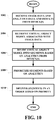
FIG. 10 is a flowchart illustrating an example method for segmentation of content delivery, according to some example embodiments. Atoperation 1002, adelivery segmentation module 202 of theserver 110 may receive image data and analytics data and results from one or more devices. - At
operation 1004, thedelivery segmentation module 202 retrieves a virtual object model associated with the image data. - At
operation 1006, thedelivery segmentation module 202 divides the virtual object model into segments based on analytics from the device. - At
operation 1008, thedelivery segmentation module 202 prioritizes segments based on analytics. - At
operation 1010, thedelivery segmentation module 202 delivers segments in an order based on the priority. -
FIG. 11 is a flowchart illustrating another example method for segmentation of content delivery, according to some example embodiments. - At 1102, the
delivery segmentation module 202 receives image data and view position from a device. - At 1104, the
delivery segmentation module 202 retrieves virtual object model associated with image data. - At 1106, the
delivery segmentation module 202 divides virtual object model into segments based on the view position. - At 1108, the
delivery segmentation module 202 prioritizes segments based on view position. - At 1110, the
delivery segmentation module 202 delivers segments in an order based on priority. -
FIG. 12 is a block diagram illustrating components of amachine 1200, according to some example embodiments, able to read instructions from a machine-readable medium (e.g., a machine-readable storage medium, a computer-readable storage medium, or any suitable combination thereof) and perform any one or more of the methodologies discussed herein, in whole or in part. Specifically,FIG. 12 shows a diagrammatic representation of themachine 1200 in the example form of a computer system and within which instructions 1224 (e.g., software, a program, an application, an applet, an app, or other executable code) for causing themachine 1200 to perform any one or more of the methodologies discussed herein may be executed, in whole or in part. In alternative embodiments, themachine 1200 operates as a standalone device or may be connected (e.g., networked) to other machines. In a networked deployment, themachine 1200 may operate in the capacity of a server machine or a client machine in a server-client network environment, or as a peer machine in a distributed (e.g., peer-to-peer) network environment. Themachine 1200 may be a server computer, a client computer, a personal computer (PC), a tablet computer, a laptop computer, a netbook, a set-top box (STB), a personal digital assistant (PDA), a cellular telephone, a smartphone, a web appliance, a network router, a network switch, a network bridge, or any machine capable of executing theinstructions 1224, sequentially or otherwise, that specify actions to be taken by that machine. Further, while only a single machine is illustrated, the term "machine" shall also be taken to include a collection of machines that individually or jointly execute theinstructions 1224 to perform all or part of any one or more of the methodologies discussed herein. - The
machine 1200 includes a processor 1202 (e.g., a central processing unit (CPU), a graphics processing unit (GPU), a digital signal processor (DSP), an application specific integrated circuit (ASIC), a radiofrequency integrated circuit (RFIC), or any suitable combination thereof), amain memory 1204, and astatic memory 1206, which are configured to communicate with each other via abus 1208. Themachine 1200 may further include a graphics display 1210 (e.g., a plasma display panel (PDP), a light emitting diode (LED) display, a liquid crystal display (LCD), a projector, or a cathode ray tube (CRT)). Themachine 1200 may also include an alphanumeric input device 1212 (e.g., a keyboard), a cursor control device 1214 (e.g., a mouse, a touchpad, a trackball, a joystick, a motion sensor, or other pointing instrument), astorage unit 1216, a signal generation device 1218 (e.g., a speaker), and anetwork interface device 1220. - The
storage unit 1216 includes a machine-readable medium 1222 on which is stored theinstructions 1224 embodying any one or more of the methodologies or functions described herein. Theinstructions 1224 may also reside, completely or at least partially, within themain memory 1204, within the processor 1202 (e.g., within the processor's cache memory), or both, during execution thereof by themachine 1200. Accordingly, themain memory 1204 and theprocessor 1202 may be considered as machine-readable media. Theinstructions 1224 may be transmitted or received over a network 1226 (e.g., network 108) via thenetwork interface device 1220. - As used herein, the term "memory" refers to a machine-readable medium able to store data temporarily or permanently and may be taken to include, but not be limited to, random-access memory (RAM), read-only memory (ROM), buffer memory, flash memory, and cache memory. While the machine-
readable medium 1222 is shown in an example embodiment to be a single medium, the term "machine-readable medium" should be taken to include a single medium or multiple media (e.g., a centralized or distributed database, or associated caches and servers) able to store instructions. The term "machine-readable medium" shall also be taken to include any medium, or combination of multiple media, that is capable of storing instructions for execution by a machine (e.g., machine 1200), such that the instructions, when executed by one or more processors of the machine (e.g., processor 1202), cause the machine to perform any one or more of the methodologies described herein. Accordingly, a "machine-readable medium" refers to a single storage apparatus or device, as well as "cloud-based" storage systems or storage networks that include multiple storage apparatus or devices. The term "machine-readable medium" shall accordingly be taken to include, but not be limited to, one or more data repositories in the form of a solid-state memory, an optical medium, a magnetic medium, or any suitable combination thereof. - Throughout this specification, plural instances may implement components, operations, or structures described as a single instance. Although individual operations of one or more methods are illustrated and described as separate operations, one or more of the individual operations may be performed concurrently, and nothing requires that the operations be performed in the order illustrated. Structures and functionality presented as separate components in example configurations may be implemented as a combined structure or component. Similarly, structures and functionality presented as a single component may be implemented as separate components. These and other variations, modifications, additions, and improvements fall within the scope of the subject matter herein.
- Certain embodiments are described herein as including logic or a number of components, modules, or mechanisms. Modules may constitute either software modules (e.g., code embodied on a machine-readable medium or in a transmission signal) or hardware modules. A "hardware module" is a tangible unit capable of performing certain operations and may be configured or arranged in a certain physical manner. In various example embodiments, one or more computer systems (e.g., a standalone computer system, a client computer system, or a server computer system) or one or more hardware modules of a computer system (e.g., a processor or a group of processors) may be configured by software (e.g., an application or application portion) as a hardware module that operates to perform certain operations as described herein.
- In some embodiments, a hardware module may be implemented mechanically, electronically, or any suitable combination thereof. For example, a hardware module may include dedicated circuitry or logic that is permanently configured to perform certain operations. For example, a hardware module may be a special-purpose processor, such as a field programmable gate array (FPGA) or an ASIC. A hardware module may also include programmable logic or circuitry that is temporarily configured by software to perform certain operations. For example, a hardware module may include software encompassed within a general-purpose processor or other programmable processor. It will be appreciated that the decision to implement a hardware module mechanically, in dedicated and permanently configured circuitry, or in temporarily configured circuitry (e.g., configured by software) may be driven by cost and time considerations.
- Accordingly, the phrase "hardware module" should be understood to encompass a tangible entity, be that an entity that is physically constructed, permanently configured (e.g., hardwired), or temporarily configured (e.g., programmed) to operate in a certain manner or to perform certain operations described herein. As used herein, "hardware-implemented module" refers to a hardware module. Considering embodiments in which hardware modules are temporarily configured (e.g., programmed), each of the hardware modules need not be configured or instantiated at any one instance in time. For example, where a hardware module comprises a general-purpose processor configured by software to become a special-purpose processor, the general-purpose processor may be configured as respectively different special-purpose processors (e.g., comprising different hardware modules) at different times. Software may accordingly configure a processor, for example, to constitute a particular hardware module at one instance of time and to constitute a different hardware module at a different instance of time.
- Hardware modules can provide information to, and receive information from, other hardware modules. Accordingly, the described hardware modules may be regarded as being communicatively coupled. Where multiple hardware modules exist contemporaneously, communications may be achieved through signal transmission (e.g., over appropriate circuits and buses) between or among two or more of the hardware modules. In embodiments in which multiple hardware modules are configured or instantiated at different times, communications between such hardware modules may be achieved, for example, through the storage and retrieval of information in memory structures to which the multiple hardware modules have access. For example, one hardware module may perform an operation and store the output of that operation in a memory device to which it is communicatively coupled. A further hardware module may then, at a later time, access the memory device to retrieve and process the stored output. Hardware modules may also initiate communications with input or output devices, and can operate on a resource (e.g., a collection of information).
- The various operations of example methods described herein may be performed, at least partially, by one or more processors that are temporarily configured (e.g., by software) or permanently configured to perform the relevant operations. Whether temporarily or permanently configured, such processors may constitute processor-implemented modules that operate to perform one or more operations or functions described herein. As used herein, "processor-implemented module" refers to a hardware module implemented using one or more processors.
- Similarly, the methods described herein may be at least partially processor-implemented, a processor being an example of hardware. For example, at least some of the operations of a method may be performed by one or more processors or processor-implemented modules. Moreover, the one or more processors may also operate to support performance of the relevant operations in a "cloud computing" environment or as a "software as a service" (SaaS). For example, at least some of the operations may be performed by a group of computers (as examples of machines including processors), with these operations being accessible via a network (e.g., the Internet) and via one or more appropriate interfaces (e.g., an application program interface (API)).
- The performance of certain of the operations may be distributed among the one or more processors, not only residing within a single machine, but deployed across a number of machines. In some example embodiments, the one or more processors or processor-implemented modules may be located in a single geographic location (e.g., within a home environment, an office environment, or a server farm). In other example embodiments, the one or more processors or processor-implemented modules may be distributed across a number of geographic locations.
- Some portions of the subject matter discussed herein may be presented in terms of algorithms or symbolic representations of operations on data stored as bits or binary digital signals within a machine memory (e.g., a computer memory). Such algorithms or symbolic representations are examples of techniques used by those of ordinary skill in the data processing arts to convey the substance of their work to others skilled in the art. As used herein, an "algorithm" is a self-consistent sequence of operations or similar processing leading to a desired result. In this context, algorithms and operations involve physical manipulation of physical quantities. Typically, but not necessarily, such quantities may take the form of electrical, magnetic, or optical signals capable of being stored, accessed, transferred, combined, compared, or otherwise manipulated by a machine. It is convenient at times, principally for reasons of common usage, to refer to such signals using words such as "data," "content," "bits," "values," "elements," "symbols," "characters," "terms," "numbers," "numerals," or the like. These words, however, are merely convenient labels and are to be associated with appropriate physical quantities.
- Unless specifically stated otherwise, discussions herein using words such as "processing," "computing," "calculating," "determining," "presenting," "displaying," or the like may refer to actions or processes of a machine (e.g., a computer) that manipulates or transforms data represented as physical (e.g., electronic, magnetic, or optical) quantities within one or more memories (e.g., volatile memory, non-volatile memory, or any suitable combination thereof), registers, or other machine components that receive, store, transmit, or display information. Furthermore, unless specifically stated otherwise, the terms "a" or "an" are herein used, as is common in patent documents, to include one or more than one instance. Finally, as used herein, the conjunction "or" refers to a non-exclusive "or," unless specifically stated otherwise.
Claims (8)
- A server (110) comprising:a memory (208) configured to store a three-dimensional model of a virtual object (104, 106); anda hardware processor implemented by a delivery segmentation module (202) configured to:divide the three-dimensional model into a plurality of segments (912, 914, 916), each segment of the three-dimensional model corresponding to a part of the virtual object;determine a position and an orientation of a device (101, 901) in relation to a physical object (904);divide the three-dimensional model (304) into a first and a second segment of the plurality of segments based on the position and the orientation of the device in relation to the physical object, the first segment including parts of the virtual object visible from the device, the second segment including parts of the virtual object not visible from the device;characterised in that the delivery segmentation module (202) is configured to:generate analytics results (214) based on analytics data (402, 404) received from a plurality of devices, the analytics results identifying a rate at which each feature of the three-dimensional model is interacted with and a rate at which each location on the three-dimensional model is viewed by the plurality of devices;divide the three-dimensional model (302) into a third and a fourth segment of the plurality of segments based on the analytics results, a feature included in the third segment being interacted with most often, a location corresponding to the third segment being viewed most often;arrange an order (306) of the plurality of segments in a delivery queue (410, 412) based on the analytics results (214) and based on the position and the orientation of the device in relation to the physical object, the first segment being queued before the second segment in the delivery queue, the third segment being queued before the fourth segment in the delivery queue; anddeliver each segment (306) in accordance with the order of the delivery queue to the device (101, 110) that is configured to recognize the physical object that is associated with the three-dimensional model of the virtual object.
- The server (110) of claim 1, wherein the delivery segmentation module (202) is configured to:determine a fifth segment corresponding to a first externally visible surface part (802) of the virtual object (810),determine a sixth segment corresponding to a second externally visible surface part (804) of the virtual object,determine that the fifth segment is in a line of sight between the device and the sixth segment, anddeliver the fifth segment to the device (110) prior to the sixth segment, the sixth segment rendered at the device after the fifth segment is rendered at the device.
- The server (110) of claim 1, wherein the delivery segmentation module (202) is configured to:determine a fifth segment corresponding to a part of a first virtual object (806), anddetermine a sixth segment corresponding to a part of a second virtual object (808),determine that the fifth segment is in a line of sight between the device (101) and the sixth segment, anddeliver the fifth segment to the device prior to the sixth segment, the sixth segment rendered at the device after the fifth segment is rendered at the device.
- The server (110) of claim 1, wherein the delivery segmentation module (202) is configured to:
receive pose estimation data (502) of the device relative to the physical object captured with the device, pose duration data (504) of the device relative to the physical object captured with the device, pose orientation data (506) of the device relative to the physical object captured with the device, and pose interaction data (508) of the device relative to the physical object captured with the device. - A computer-implemented method comprising:dividing a three-dimensional model of a virtual object into a plurality of segments (912, 914, 916), each segment of the three-dimensional model corresponding to a part of the virtual object;determining a position and an orientation of a device (101, 901) in relation to a physical object (904);dividing the three-dimensional model (304) into a first and a second segment of the plurality of segments based on the position and the orientation of the device in relation to the physical object, the first segment including parts of the virtual object visible from the device, the second segment including parts of the virtual object not visible from the device;characterised by:generating analytics results (214) based on analytics data (402, 404) received from a plurality of devices, the analytics results identifying a rate at which each feature of the three-dimensional model is interacted with and a rate at which each location on the three-dimensional model is viewed by the plurality of devices;dividing the three-dimensional model (302) into a third and a fourth segment of the plurality of segments based on the analytics results, a feature corresponding to the third segment being operated on most often, a location corresponding to the third segment being viewed most often;arranging an order (306) of the plurality of segments in a delivery queue (410, 412) based on the analytics results (214) and based on the position and the orientation of the device in relation to the physical object, the first segment being queued before the second segment in the delivery queue, the third segment being queued before the fourth segment in the delivery queue; anddelivering each segment (306) in accordance with the order of the delivery queue to the device (101, 110) that is configured to recognize the physical object that is associated with the three-dimensional model of the virtual object.
- The computer-implemented method of claim 5, further comprising:determining a fifth segment corresponding to a first externally visible surface part (802) of the virtual object (810);determining a sixth segment corresponding to a second externally visible surface part (804) of the virtual object (810);determining that the fifth segment is in a line of sight between the device (101) and the sixth segment; anddelivering the fifth segment to the device prior to the sixth segment, the sixth segment rendered at the device after the fifth segment is rendered at the device.
- The computer-implemented method of claim 5, further comprising:determining a fifth segment corresponding to a part of a first virtual object (806);determining a sixth segment corresponding to a part of a second virtual object (808);determining that the fifth segment is in a line of sight between the device and the sixth segment; anddelivering the fifth segment to the device (101) prior to the sixth segment, the sixth segment rendered at the device after the fifth segment is rendered at the device.
- A non-transitory machine-readable storage medium (1222) comprising instructions (1224) that, when executed by one or more processors of a machine (1200), cause the machine to perform operations comprising:dividing a three-dimensional model of a virtual object into a plurality of segments (912, 914, 916), each segment of the three-dimensional model corresponding to a part of the virtual object;determining a position and an orientation of a device (101, 901) in relation to a physical object (904);dividing the three-dimensional model (304) into a first and a second segment of the plurality of segments based on the position and the orientation of the device in relation to the physical object, the first segment including parts of the virtual object visible from the device, the second segment including parts of the virtual object not visible from the device;characterised by:generating analytics results (214) based on analytics data (402, 404) received from a plurality of devices, the analytics results identifying a rate at which each feature of the three-dimensional model is interacted with and a rate at which each location on the three-dimensional model is viewed by the plurality of devices;dividing the three-dimensional model (302) into a third and a fourth segment of the plurality of segments based on the analytics results, a feature corresponding to the third segment being operated on most often, a location corresponding to the third segment being viewed most often;arranging an order (306) of the plurality of segments in a delivery queue (410, 412) based on the analytics results (214) and based on the position and the orientation of the device in relation to the physical object, the first segment being queued before the second segment in the delivery queue, the third segment being queued before the fourth segment in the delivery queue; anddelivering each segment (306) in accordance with the order of the delivery queue to the device (101, 110) that is configured to recognize the physical object that is associated with the three-dimensional model of the virtual object.
Applications Claiming Priority (2)
| Application Number | Priority Date | Filing Date | Title |
|---|---|---|---|
| US13/840,097 US9495748B2 (en) | 2013-03-15 | 2013-03-15 | Segmentation of content delivery |
| PCT/US2014/024765 WO2014151015A1 (en) | 2013-03-15 | 2014-03-12 | Segmentation of content delivery |
Publications (3)
| Publication Number | Publication Date |
|---|---|
| EP2972950A1 EP2972950A1 (en) | 2016-01-20 |
| EP2972950A4 EP2972950A4 (en) | 2016-08-17 |
| EP2972950B1 true EP2972950B1 (en) | 2018-07-25 |
Family
ID=51525474
Family Applications (1)
| Application Number | Title | Priority Date | Filing Date |
|---|---|---|---|
| EP14769352.7A Not-in-force EP2972950B1 (en) | 2013-03-15 | 2014-03-12 | Segmentation of content delivery |
Country Status (7)
| Country | Link |
|---|---|
| US (1) | US9495748B2 (en) |
| EP (1) | EP2972950B1 (en) |
| JP (1) | JP6190035B2 (en) |
| KR (1) | KR101732839B1 (en) |
| AU (1) | AU2014235369B2 (en) |
| NZ (1) | NZ713311A (en) |
| WO (1) | WO2014151015A1 (en) |
Families Citing this family (11)
| Publication number | Priority date | Publication date | Assignee | Title |
|---|---|---|---|---|
| US9671566B2 (en) | 2012-06-11 | 2017-06-06 | Magic Leap, Inc. | Planar waveguide apparatus with diffraction element(s) and system employing same |
| WO2014145193A1 (en) * | 2013-03-15 | 2014-09-18 | Nexref Technologies, Llc | Marker-based augmented reality (ar) display with inventory management |
| US9495748B2 (en) | 2013-03-15 | 2016-11-15 | Daqri, Llc | Segmentation of content delivery |
| US9262865B2 (en) | 2013-03-15 | 2016-02-16 | Daqri, Llc | Content creation tool |
| US10262462B2 (en) | 2014-04-18 | 2019-04-16 | Magic Leap, Inc. | Systems and methods for augmented and virtual reality |
| WO2015006784A2 (en) | 2013-07-12 | 2015-01-15 | Magic Leap, Inc. | Planar waveguide apparatus with diffraction element(s) and system employing same |
| US10533850B2 (en) | 2013-07-12 | 2020-01-14 | Magic Leap, Inc. | Method and system for inserting recognized object data into a virtual world |
| US10289932B2 (en) * | 2017-07-31 | 2019-05-14 | Google Llc | Object recognition state indicators |
| WO2020242047A1 (en) * | 2019-05-30 | 2020-12-03 | Samsung Electronics Co., Ltd. | Method and apparatus for acquiring virtual object data in augmented reality |
| CN112580412A (en) * | 2019-09-30 | 2021-03-30 | 百度(美国)有限责任公司 | Commodity identification method and device |
| KR102396944B1 (en) * | 2019-10-17 | 2022-05-13 | 주식회사 듀얼아이엔씨 | System modeling method sysem interoperability method and for physical system and virtual system based on the segment |
Family Cites Families (15)
| Publication number | Priority date | Publication date | Assignee | Title |
|---|---|---|---|---|
| US6052125A (en) * | 1998-01-07 | 2000-04-18 | Evans & Sutherland Computer Corporation | Method for reducing the rendering load for high depth complexity scenes on a computer graphics display |
| US6909723B1 (en) | 2000-08-04 | 2005-06-21 | Intellon Corporation | Segment bursting with priority pre-emption and reduced latency |
| JP2002318807A (en) | 2001-04-19 | 2002-10-31 | Matsushita Electric Ind Co Ltd | Meta-data generation device and meta-data generation method |
| US7643024B2 (en) * | 2001-05-17 | 2010-01-05 | The Trustees Of Columbia University In The City Of New York | System and method for view management in three dimensional space |
| KR20060069497A (en) * | 2003-09-24 | 2006-06-21 | 노키아 코포레이션 | Improved presentation of large objects on small displays |
| US8370514B2 (en) | 2005-04-28 | 2013-02-05 | DISH Digital L.L.C. | System and method of minimizing network bandwidth retrieved from an external network |
| US7783773B2 (en) | 2006-07-24 | 2010-08-24 | Microsoft Corporation | Glitch-free media streaming |
| WO2009048550A2 (en) | 2007-10-09 | 2009-04-16 | Keep In Touch, Inc. | Time sensitive scheduling data delivery network |
| US9600067B2 (en) * | 2008-10-27 | 2017-03-21 | Sri International | System and method for generating a mixed reality environment |
| US8335348B2 (en) * | 2009-12-14 | 2012-12-18 | Indian Institute Of Technology Bombay | Visual object tracking with scale and orientation adaptation |
| JP2012058968A (en) * | 2010-09-08 | 2012-03-22 | Namco Bandai Games Inc | Program, information storage medium and image generation system |
| JP5762892B2 (en) * | 2011-09-06 | 2015-08-12 | ビッグローブ株式会社 | Information display system, information display method, and information display program |
| US20130218461A1 (en) * | 2012-02-22 | 2013-08-22 | Leonid Naimark | Reduced Drift Dead Reckoning System |
| US9389420B2 (en) * | 2012-06-14 | 2016-07-12 | Qualcomm Incorporated | User interface interaction for transparent head-mounted displays |
| US9495748B2 (en) | 2013-03-15 | 2016-11-15 | Daqri, Llc | Segmentation of content delivery |
-
2013
- 2013-03-15 US US13/840,097 patent/US9495748B2/en active Active
-
2014
- 2014-03-12 JP JP2016501635A patent/JP6190035B2/en active Active
- 2014-03-12 EP EP14769352.7A patent/EP2972950B1/en not_active Not-in-force
- 2014-03-12 NZ NZ713311A patent/NZ713311A/en not_active IP Right Cessation
- 2014-03-12 KR KR1020157029855A patent/KR101732839B1/en active IP Right Grant
- 2014-03-12 WO PCT/US2014/024765 patent/WO2014151015A1/en active Application Filing
- 2014-03-12 AU AU2014235369A patent/AU2014235369B2/en not_active Ceased
Non-Patent Citations (1)
| Title |
|---|
| None * |
Also Published As
| Publication number | Publication date |
|---|---|
| US20140267407A1 (en) | 2014-09-18 |
| AU2014235369A1 (en) | 2015-11-05 |
| NZ713311A (en) | 2017-10-27 |
| US9495748B2 (en) | 2016-11-15 |
| EP2972950A4 (en) | 2016-08-17 |
| JP2016517580A (en) | 2016-06-16 |
| JP6190035B2 (en) | 2017-08-30 |
| KR20150132527A (en) | 2015-11-25 |
| EP2972950A1 (en) | 2016-01-20 |
| AU2014235369B2 (en) | 2017-02-02 |
| WO2014151015A1 (en) | 2014-09-25 |
| KR101732839B1 (en) | 2017-05-04 |
Similar Documents
| Publication | Publication Date | Title |
|---|---|---|
| US11710279B2 (en) | Contextual local image recognition dataset | |
| EP2972950B1 (en) | Segmentation of content delivery | |
| US10147239B2 (en) | Content creation tool | |
| US9760777B2 (en) | Campaign optimization for experience content dataset | |
| AU2014235416B2 (en) | Real world analytics visualization |
Legal Events
| Date | Code | Title | Description |
|---|---|---|---|
| PUAI | Public reference made under article 153(3) epc to a published international application that has entered the european phase |
Free format text: ORIGINAL CODE: 0009012 |
|
| 17P | Request for examination filed |
Effective date: 20151015 |
|
| AK | Designated contracting states |
Kind code of ref document: A1 Designated state(s): AL AT BE BG CH CY CZ DE DK EE ES FI FR GB GR HR HU IE IS IT LI LT LU LV MC MK MT NL NO PL PT RO RS SE SI SK SM TR |
|
| AX | Request for extension of the european patent |
Extension state: BA ME |
|
| DAX | Request for extension of the european patent (deleted) | ||
| A4 | Supplementary search report drawn up and despatched |
Effective date: 20160718 |
|
| RIC1 | Information provided on ipc code assigned before grant |
Ipc: G06F 15/16 20060101AFI20160712BHEP Ipc: G06T 15/20 20110101ALI20160712BHEP |
|
| STAA | Information on the status of an ep patent application or granted ep patent |
Free format text: STATUS: EXAMINATION IS IN PROGRESS |
|
| 17Q | First examination report despatched |
Effective date: 20170407 |
|
| GRAP | Despatch of communication of intention to grant a patent |
Free format text: ORIGINAL CODE: EPIDOSNIGR1 |
|
| STAA | Information on the status of an ep patent application or granted ep patent |
Free format text: STATUS: GRANT OF PATENT IS INTENDED |
|
| INTG | Intention to grant announced |
Effective date: 20180112 |
|
| GRAJ | Information related to disapproval of communication of intention to grant by the applicant or resumption of examination proceedings by the epo deleted |
Free format text: ORIGINAL CODE: EPIDOSDIGR1 |
|
| STAA | Information on the status of an ep patent application or granted ep patent |
Free format text: STATUS: EXAMINATION IS IN PROGRESS |
|
| GRAR | Information related to intention to grant a patent recorded |
Free format text: ORIGINAL CODE: EPIDOSNIGR71 |
|
| GRAS | Grant fee paid |
Free format text: ORIGINAL CODE: EPIDOSNIGR3 |
|
| STAA | Information on the status of an ep patent application or granted ep patent |
Free format text: STATUS: GRANT OF PATENT IS INTENDED |
|
| GRAA | (expected) grant |
Free format text: ORIGINAL CODE: 0009210 |
|
| STAA | Information on the status of an ep patent application or granted ep patent |
Free format text: STATUS: THE PATENT HAS BEEN GRANTED |
|
| INTC | Intention to grant announced (deleted) | ||
| INTG | Intention to grant announced |
Effective date: 20180613 |
|
| AK | Designated contracting states |
Kind code of ref document: B1 Designated state(s): AL AT BE BG CH CY CZ DE DK EE ES FI FR GB GR HR HU IE IS IT LI LT LU LV MC MK MT NL NO PL PT RO RS SE SI SK SM TR |
|
| REG | Reference to a national code |
Ref country code: GB Ref legal event code: FG4D |
|
| REG | Reference to a national code |
Ref country code: CH Ref legal event code: EP |
|
| REG | Reference to a national code |
Ref country code: AT Ref legal event code: REF Ref document number: 1022504 Country of ref document: AT Kind code of ref document: T Effective date: 20180815 |
|
| REG | Reference to a national code |
Ref country code: IE Ref legal event code: FG4D |
|
| REG | Reference to a national code |
Ref country code: DE Ref legal event code: R096 Ref document number: 602014029198 Country of ref document: DE |
|
| REG | Reference to a national code |
Ref country code: NL Ref legal event code: MP Effective date: 20180725 |
|
| REG | Reference to a national code |
Ref country code: LT Ref legal event code: MG4D |
|
| PG25 | Lapsed in a contracting state [announced via postgrant information from national office to epo] |
Ref country code: NL Free format text: LAPSE BECAUSE OF FAILURE TO SUBMIT A TRANSLATION OF THE DESCRIPTION OR TO PAY THE FEE WITHIN THE PRESCRIBED TIME-LIMIT Effective date: 20180725 |
|
| REG | Reference to a national code |
Ref country code: AT Ref legal event code: MK05 Ref document number: 1022504 Country of ref document: AT Kind code of ref document: T Effective date: 20180725 |
|
| PG25 | Lapsed in a contracting state [announced via postgrant information from national office to epo] |
Ref country code: GR Free format text: LAPSE BECAUSE OF FAILURE TO SUBMIT A TRANSLATION OF THE DESCRIPTION OR TO PAY THE FEE WITHIN THE PRESCRIBED TIME-LIMIT Effective date: 20181026 Ref country code: NO Free format text: LAPSE BECAUSE OF FAILURE TO SUBMIT A TRANSLATION OF THE DESCRIPTION OR TO PAY THE FEE WITHIN THE PRESCRIBED TIME-LIMIT Effective date: 20181025 Ref country code: AT Free format text: LAPSE BECAUSE OF FAILURE TO SUBMIT A TRANSLATION OF THE DESCRIPTION OR TO PAY THE FEE WITHIN THE PRESCRIBED TIME-LIMIT Effective date: 20180725 Ref country code: BG Free format text: LAPSE BECAUSE OF FAILURE TO SUBMIT A TRANSLATION OF THE DESCRIPTION OR TO PAY THE FEE WITHIN THE PRESCRIBED TIME-LIMIT Effective date: 20181025 Ref country code: LT Free format text: LAPSE BECAUSE OF FAILURE TO SUBMIT A TRANSLATION OF THE DESCRIPTION OR TO PAY THE FEE WITHIN THE PRESCRIBED TIME-LIMIT Effective date: 20180725 Ref country code: RS Free format text: LAPSE BECAUSE OF FAILURE TO SUBMIT A TRANSLATION OF THE DESCRIPTION OR TO PAY THE FEE WITHIN THE PRESCRIBED TIME-LIMIT Effective date: 20180725 Ref country code: IS Free format text: LAPSE BECAUSE OF FAILURE TO SUBMIT A TRANSLATION OF THE DESCRIPTION OR TO PAY THE FEE WITHIN THE PRESCRIBED TIME-LIMIT Effective date: 20181125 Ref country code: PL Free format text: LAPSE BECAUSE OF FAILURE TO SUBMIT A TRANSLATION OF THE DESCRIPTION OR TO PAY THE FEE WITHIN THE PRESCRIBED TIME-LIMIT Effective date: 20180725 Ref country code: SE Free format text: LAPSE BECAUSE OF FAILURE TO SUBMIT A TRANSLATION OF THE DESCRIPTION OR TO PAY THE FEE WITHIN THE PRESCRIBED TIME-LIMIT Effective date: 20180725 Ref country code: FI Free format text: LAPSE BECAUSE OF FAILURE TO SUBMIT A TRANSLATION OF THE DESCRIPTION OR TO PAY THE FEE WITHIN THE PRESCRIBED TIME-LIMIT Effective date: 20180725 |
|
| PG25 | Lapsed in a contracting state [announced via postgrant information from national office to epo] |
Ref country code: AL Free format text: LAPSE BECAUSE OF FAILURE TO SUBMIT A TRANSLATION OF THE DESCRIPTION OR TO PAY THE FEE WITHIN THE PRESCRIBED TIME-LIMIT Effective date: 20180725 Ref country code: LV Free format text: LAPSE BECAUSE OF FAILURE TO SUBMIT A TRANSLATION OF THE DESCRIPTION OR TO PAY THE FEE WITHIN THE PRESCRIBED TIME-LIMIT Effective date: 20180725 Ref country code: HR Free format text: LAPSE BECAUSE OF FAILURE TO SUBMIT A TRANSLATION OF THE DESCRIPTION OR TO PAY THE FEE WITHIN THE PRESCRIBED TIME-LIMIT Effective date: 20180725 |
|
| REG | Reference to a national code |
Ref country code: DE Ref legal event code: R097 Ref document number: 602014029198 Country of ref document: DE |
|
| PG25 | Lapsed in a contracting state [announced via postgrant information from national office to epo] |
Ref country code: EE Free format text: LAPSE BECAUSE OF FAILURE TO SUBMIT A TRANSLATION OF THE DESCRIPTION OR TO PAY THE FEE WITHIN THE PRESCRIBED TIME-LIMIT Effective date: 20180725 Ref country code: IT Free format text: LAPSE BECAUSE OF FAILURE TO SUBMIT A TRANSLATION OF THE DESCRIPTION OR TO PAY THE FEE WITHIN THE PRESCRIBED TIME-LIMIT Effective date: 20180725 Ref country code: ES Free format text: LAPSE BECAUSE OF FAILURE TO SUBMIT A TRANSLATION OF THE DESCRIPTION OR TO PAY THE FEE WITHIN THE PRESCRIBED TIME-LIMIT Effective date: 20180725 Ref country code: RO Free format text: LAPSE BECAUSE OF FAILURE TO SUBMIT A TRANSLATION OF THE DESCRIPTION OR TO PAY THE FEE WITHIN THE PRESCRIBED TIME-LIMIT Effective date: 20180725 Ref country code: CZ Free format text: LAPSE BECAUSE OF FAILURE TO SUBMIT A TRANSLATION OF THE DESCRIPTION OR TO PAY THE FEE WITHIN THE PRESCRIBED TIME-LIMIT Effective date: 20180725 |
|
| PG25 | Lapsed in a contracting state [announced via postgrant information from national office to epo] |
Ref country code: SK Free format text: LAPSE BECAUSE OF FAILURE TO SUBMIT A TRANSLATION OF THE DESCRIPTION OR TO PAY THE FEE WITHIN THE PRESCRIBED TIME-LIMIT Effective date: 20180725 Ref country code: SM Free format text: LAPSE BECAUSE OF FAILURE TO SUBMIT A TRANSLATION OF THE DESCRIPTION OR TO PAY THE FEE WITHIN THE PRESCRIBED TIME-LIMIT Effective date: 20180725 Ref country code: DK Free format text: LAPSE BECAUSE OF FAILURE TO SUBMIT A TRANSLATION OF THE DESCRIPTION OR TO PAY THE FEE WITHIN THE PRESCRIBED TIME-LIMIT Effective date: 20180725 |
|
| PLBE | No opposition filed within time limit |
Free format text: ORIGINAL CODE: 0009261 |
|
| STAA | Information on the status of an ep patent application or granted ep patent |
Free format text: STATUS: NO OPPOSITION FILED WITHIN TIME LIMIT |
|
| 26N | No opposition filed |
Effective date: 20190426 |
|
| PG25 | Lapsed in a contracting state [announced via postgrant information from national office to epo] |
Ref country code: SI Free format text: LAPSE BECAUSE OF FAILURE TO SUBMIT A TRANSLATION OF THE DESCRIPTION OR TO PAY THE FEE WITHIN THE PRESCRIBED TIME-LIMIT Effective date: 20180725 |
|
| REG | Reference to a national code |
Ref country code: GB Ref legal event code: 732E Free format text: REGISTERED BETWEEN 20190919 AND 20190925 |
|
| PG25 | Lapsed in a contracting state [announced via postgrant information from national office to epo] |
Ref country code: MC Free format text: LAPSE BECAUSE OF FAILURE TO SUBMIT A TRANSLATION OF THE DESCRIPTION OR TO PAY THE FEE WITHIN THE PRESCRIBED TIME-LIMIT Effective date: 20180725 |
|
| REG | Reference to a national code |
Ref country code: CH Ref legal event code: PL |
|
| PG25 | Lapsed in a contracting state [announced via postgrant information from national office to epo] |
Ref country code: LU Free format text: LAPSE BECAUSE OF NON-PAYMENT OF DUE FEES Effective date: 20190312 |
|
| REG | Reference to a national code |
Ref country code: BE Ref legal event code: MM Effective date: 20190331 |
|
| PG25 | Lapsed in a contracting state [announced via postgrant information from national office to epo] |
Ref country code: LI Free format text: LAPSE BECAUSE OF NON-PAYMENT OF DUE FEES Effective date: 20190331 Ref country code: CH Free format text: LAPSE BECAUSE OF NON-PAYMENT OF DUE FEES Effective date: 20190331 Ref country code: IE Free format text: LAPSE BECAUSE OF NON-PAYMENT OF DUE FEES Effective date: 20190312 |
|
| PG25 | Lapsed in a contracting state [announced via postgrant information from national office to epo] |
Ref country code: BE Free format text: LAPSE BECAUSE OF NON-PAYMENT OF DUE FEES Effective date: 20190331 |
|
| PG25 | Lapsed in a contracting state [announced via postgrant information from national office to epo] |
Ref country code: TR Free format text: LAPSE BECAUSE OF FAILURE TO SUBMIT A TRANSLATION OF THE DESCRIPTION OR TO PAY THE FEE WITHIN THE PRESCRIBED TIME-LIMIT Effective date: 20180725 |
|
| PGFP | Annual fee paid to national office [announced via postgrant information from national office to epo] |
Ref country code: GB Payment date: 20200327 Year of fee payment: 7 Ref country code: DE Payment date: 20200327 Year of fee payment: 7 |
|
| PG25 | Lapsed in a contracting state [announced via postgrant information from national office to epo] |
Ref country code: MT Free format text: LAPSE BECAUSE OF NON-PAYMENT OF DUE FEES Effective date: 20190312 Ref country code: PT Free format text: LAPSE BECAUSE OF FAILURE TO SUBMIT A TRANSLATION OF THE DESCRIPTION OR TO PAY THE FEE WITHIN THE PRESCRIBED TIME-LIMIT Effective date: 20181125 |
|
| PGFP | Annual fee paid to national office [announced via postgrant information from national office to epo] |
Ref country code: FR Payment date: 20200325 Year of fee payment: 7 |
|
| REG | Reference to a national code |
Ref country code: DE Ref legal event code: R081 Ref document number: 602014029198 Country of ref document: DE Owner name: RPX CORPORATION, SAN FRANCISCO, US Free format text: FORMER OWNER: DAQRI, LLC, LOS ANGELES, CALIF., US |
|
| PG25 | Lapsed in a contracting state [announced via postgrant information from national office to epo] |
Ref country code: CY Free format text: LAPSE BECAUSE OF FAILURE TO SUBMIT A TRANSLATION OF THE DESCRIPTION OR TO PAY THE FEE WITHIN THE PRESCRIBED TIME-LIMIT Effective date: 20180725 |
|
| REG | Reference to a national code |
Ref country code: GB Ref legal event code: 732E Free format text: REGISTERED BETWEEN 20210603 AND 20210609 |
|
| PG25 | Lapsed in a contracting state [announced via postgrant information from national office to epo] |
Ref country code: HU Free format text: LAPSE BECAUSE OF FAILURE TO SUBMIT A TRANSLATION OF THE DESCRIPTION OR TO PAY THE FEE WITHIN THE PRESCRIBED TIME-LIMIT; INVALID AB INITIO Effective date: 20140312 |
|
| REG | Reference to a national code |
Ref country code: DE Ref legal event code: R119 Ref document number: 602014029198 Country of ref document: DE |
|
| GBPC | Gb: european patent ceased through non-payment of renewal fee |
Effective date: 20210312 |
|
| PG25 | Lapsed in a contracting state [announced via postgrant information from national office to epo] |
Ref country code: DE Free format text: LAPSE BECAUSE OF NON-PAYMENT OF DUE FEES Effective date: 20211001 Ref country code: FR Free format text: LAPSE BECAUSE OF NON-PAYMENT OF DUE FEES Effective date: 20210331 Ref country code: GB Free format text: LAPSE BECAUSE OF NON-PAYMENT OF DUE FEES Effective date: 20210312 |
|
| PG25 | Lapsed in a contracting state [announced via postgrant information from national office to epo] |
Ref country code: MK Free format text: LAPSE BECAUSE OF FAILURE TO SUBMIT A TRANSLATION OF THE DESCRIPTION OR TO PAY THE FEE WITHIN THE PRESCRIBED TIME-LIMIT Effective date: 20180725 |