EP2972596B1 - Temperature driven drive system - Google Patents
Temperature driven drive system Download PDFInfo
- Publication number
- EP2972596B1 EP2972596B1 EP14729432.6A EP14729432A EP2972596B1 EP 2972596 B1 EP2972596 B1 EP 2972596B1 EP 14729432 A EP14729432 A EP 14729432A EP 2972596 B1 EP2972596 B1 EP 2972596B1
- Authority
- EP
- European Patent Office
- Prior art keywords
- bellows
- gear
- movement
- fluid
- drive system
- Prior art date
- Legal status (The legal status is an assumption and is not a legal conclusion. Google has not performed a legal analysis and makes no representation as to the accuracy of the status listed.)
- Active
Links
Images









Classifications
-
- G—PHYSICS
- G04—HOROLOGY
- G04B—MECHANICALLY-DRIVEN CLOCKS OR WATCHES; MECHANICAL PARTS OF CLOCKS OR WATCHES IN GENERAL; TIME PIECES USING THE POSITION OF THE SUN, MOON OR STARS
- G04B5/00—Automatic winding up
- G04B5/22—Automatic winding up by thermometric, barometric or like effects or alterations
-
- G—PHYSICS
- G04—HOROLOGY
- G04B—MECHANICALLY-DRIVEN CLOCKS OR WATCHES; MECHANICAL PARTS OF CLOCKS OR WATCHES IN GENERAL; TIME PIECES USING THE POSITION OF THE SUN, MOON OR STARS
- G04B1/00—Driving mechanisms
- G04B1/10—Driving mechanisms with mainspring
- G04B1/14—Mainsprings; Bridles therefor
-
- G—PHYSICS
- G04—HOROLOGY
- G04B—MECHANICALLY-DRIVEN CLOCKS OR WATCHES; MECHANICAL PARTS OF CLOCKS OR WATCHES IN GENERAL; TIME PIECES USING THE POSITION OF THE SUN, MOON OR STARS
- G04B1/00—Driving mechanisms
- G04B1/26—Driving mechanisms driven by liquids or gases; Liquid or gaseous drives for mechanically-controlled secondary clocks
-
- G—PHYSICS
- G04—HOROLOGY
- G04B—MECHANICALLY-DRIVEN CLOCKS OR WATCHES; MECHANICAL PARTS OF CLOCKS OR WATCHES IN GENERAL; TIME PIECES USING THE POSITION OF THE SUN, MOON OR STARS
- G04B5/00—Automatic winding up
- G04B5/20—Automatic winding up by movements of other objects, e.g. by opening a hand-bag, by opening a case, by opening a door; Winding up by wind power
- G04B5/203—Automatic winding up by movements of other objects, e.g. by opening a hand-bag, by opening a case, by opening a door; Winding up by wind power by liquids or gases
Definitions
- This invention relates to driving system for energizing a device, as defined in the preamble of claim 1. More particularly, the invention relates to temperature differential driven self-winding timepieces, particularly wristwatches, which are wound in response to change in temperature.
- a Pellaton mechanism comprises a lever, which is bifurcated at one end.
- the bifurcated arms are acted upon by a rotating cam or eccentric pin to produce an eccentric oscillating motion.
- Spring loaded pawls on the lever engage a ratchet wheel at spaced apart locations on the ratchet wheel causing unidirectional rotation of the ratchet with the oscillating motion of the lever induced by the winding weight or rotor, e.g. U. S. Patents 2,696,073 and 4,174,607 .
- a pinion on a bi-directionally rotatable shaft drives a linearly displaceable wig-wag gear.
- This gear engages one of two other gears dependent on the direction of rotation of the wig-wag gear.
- the gear arrangement is organized such that the mainspring barrel will always be driven in a direction to wind the mainspring.
- a thermal energy converting device according to the preamble of claim 1 is known from EP 1 101 937 .
- Self-winding wrist watches generally have a power reserve of about one and one-half to three days. This is also called autonomy.
- the terms “autonomy” and “power reserve” refer to the time a self winding wrist watch will continue to run if fully wound, but not worn.
- Various efforts to increase the power reserve of a watch have been undertaken, but still result in the watch losing all power reserve after a period of time of not being worn.
- the invention solves these and other needs in the art.
- the invention provides a drive system for energizing a device, as defined in claim 1. This and other objects of the invention are shown in further detail in the drawings, the brief description of the drawings, and detailed specification below.
- the invention relates to a drive system 10 ( FIG. 1 ) for hydro mechanical horological time pieces, e.g. time piece(s) 400, 600 ( FIGS. 4-8 ) and sub-systems thereof, as well as other devices described herein.
- time piece(s) 400, 600 FIGS. 4-8
- sub-systems thereof as well as other devices described herein.
- These exemplary time pieces use a liquid 402 in their sub-systems for a functional purpose as is described below, and are constructed from, by way of example, titanium, titanium with shot-peened and satin-finished surfaces that are brushed to a certain color, e.g. pink gold, black DLC-coated titanium, and red gold.
- a certain color e.g. pink gold, black DLC-coated titanium, and red gold.
- other metal and polymeric materials are also used in the time pieces.
- the time pieces are sized and dimensioned, by way of example, at about 48 mm in circumference to about 18 mm in thickness or depth, and can include a tapered bezel. Of course, both smaller and larger dimensions can be used such that they are readily worn on a user's forearm or wrist.
- the liquid 402, 616 ( FIGS. 4 and 6 ) is used to display the hours on a circular tube 826 ( FIG. 8 ) around the edge of the dial.
- a one or plurality of drive system 10 piston like devices 828, 830 ( FIG. 8 ) are used in conjunction with bellows 404, 406 and some or all portions thereof are visible to a user on or near the bottom of the dial 408 and are used to push and pull the liquid 402 to show the time on a circular scale 410.
- Minutes 412 are displayed on a medium sized sub dial 414 that is optionally set near the center-top 416 of the time keeping device 400.
- an optional power reserve indictor 418 is located for the manual-wing mechanical movement.
- Some or all of the interior components 404, 406, 414, 418 of the time keeping device 400 are viewable through a transparent cover 420 which is located on the top surface 422 and also optionally a second transparent cover 502 may be located on the bottom surface 500 ( FIG. 5 ) of the time keeping device 400.
- a time keeping device 600 is illustrated in FIGS. 6 and 7 in a variant of the invention.
- Bellows 602 and 604 are positioned at about the 6 o'clock position and in a "V" shaped configuration. This configuration optimises the integration of the interface 606 that connects the watch mechanisms sub-systems with the fluidic system as described below.
- a balance spring (not shown) resides at the midday position on a black bridge 608.
- At the 3 o'clock position is an "H-N-R" crown position indicator 610 and it is counterbalanced by the presence of another hand 612 as a component of a temperature indicator 614.
- Fluid 616 obeys a set of watchmaking specifications. Fluid 616 is provided in a variety of colours, e.g. red, yellow, green, and provides homogenous resistance to vibrations, shocks and temperature changes, and no alteration in the long term, foolproof water resistance of device 600.
- a fluorescein-loaded liquid 616 has done a complete round (rotation) and gets to the 06:00 - 18:00 position, the issuing pump compresses, while the bellows 602, 604 receiver expands, generating resistance and consequently an increased energy requirement.
- Bellows 602, 604 are made from an extremely fine alloy and are highly supple and resistant.
- bellows 602, 604 are made of a highly resistant, flexible electrodeposited alloy, each driven by a piston(s) 828, 830 ( FIG. 8 ).
- the shape of the bellows 602, 604 allows for the reduction of energy required for their compression, absorbs shocks and ensures solid waterproofing.
- a minute hand 618 is configured and designed in stages to perfectly fit the structure of the fluidic system and it is designed to jump after 30 minutes to avoid the bellows 602, 604.
- FIG. 7 illustrates the rear 700 of the internal structure 702 of device 600.
- the self-winding timepiece 600 further includes a plurality of bellows 602, 604 in which at least two of the bellows 602, 604 are arranged with respect to one another at an angle of greater than 1 degree to less than about 180 degrees.
- at least two of the bellows 602, 604 are oriented with respect to one another at an angle of greater than about 45 degrees to less than 110 degrees.
- bellows 602, 604 are arranged with respect to one another at an angle of 90 degrees. It is appreciated that some of the mechanically interacting components of the bellows 602, 604 also have the same angular orientation as those of the bellows 602, 604.
- FIG. 8 is a rear exploded perspective view of the time piece 400.
- Precise micro-litre quantities of fluid 402 are used in the closed circuit to provide water resistance. Due to the link between the crown and the liquid 402, the time-setting system is designed in order to avoid the liquid 402 moving around too fast and damaging the meniscus (not shown).
- a mechanical movement mechanism 822 is situated in the upper part 824 of the watch 400, and propels a cam, which pushes the piston and activates the bellows 404, 406.
- the interface provided between the mechanical movement and the hydro system is in a closed, waterproof circuit. Both are assembled separately to keep them independent, and then made to operate simultaneously.
- the invention concerns a drive system 10 for energizing a device.
- the drive system 10 includes a bellows 104 actuated drive interface 105.
- the bellows actuated drive interface 105 provides linear translational forward and backward movement (as shown in FIGS. 1 and 2 ) by fluid expansion and contraction of a heat transfer fluid 107 according to a temperature differential.
- Fluid 107 is located within a rigid reservoir 100.
- the reservoir 100 is in fluid contact with bellows 104.
- the reservoir 100 is constructed of any suitable material that acts as a heat conduit so that temperature differentials manifested externally of the drive are thermally conveyed to the fluid 107.
- bellows 104 is constructed from flexible, elastomeric materials which permit the bellows 104 to move in an axial direction with respect to the bellows main body upon changes in volumes of the fluid 107.
- An optional mechanical interface connects bellows 104 to rigid reservoir 100.
- Bellows 104 includes an accordion style body in one variant of the invention as illustrated in the Figures.
- Drive interface 105 can take one of several forms according to the use of the drive system.
- An exemplary drive interface 105 is illustrated in FIG. 2 .
- Rigid reservoir 100 is sized and dimensioned in a variety of geometric configurations. As shown in FIGS. 1 and 2 , reservoir 100 takes on a substantially circular, tubular configuration (e.g.
- substantially C-shaped or substantially U-shaped having the following dimensions which make it suitable to energize a wristwatch as well as the following properties of the fluid within the reservoir: exterior diameter - about 40 mm, interior diameter about 30 mm, thickness about 5 mm, reservoir angle about 270 degrees, reservoir volume 8247 mm 3 or there about, surface interface 19.63 mm 2 or thereabout (with disc diameter of 5 mm or thereabout), a coefficient of dilation (1/degrees C) - 0.0012 (with 3M FlourinertTM Electronic Liquid FC-40), and an expansion per 1 degree C of 9.90 mm3, a movement at the interface of 0.50 mm, an expansion at 3 degrees C (29.69), and a movement at the interface of 1.51 mm, an expansion per 50 degrees C of 494.80 mm 3 - with a movement at the interface of 25.20 mm (from 0 degrees C to +50 degrees C), and an expansion at 90 degrees C of 890.64 mm3 (from -20 degrees C to +70 degrees C) with a
- the system includes a fluid with a high thermal expansion coefficient in another variant of the invention.
- the shape and construction of the bellows 104 as well as its stiffness is adapted or modulated, to prevent damage to the device at the temperature extremes.
- a compound bellows 104' is provided, made up of a large bellows 200 and a smaller bellows 202.
- the compound bellows 104' has variable cross-sections at levels 204 and 206 as shown in the figures.
- the stiffness of zone A is significantly higher than the stiffness of zone B (of the smaller bellows 202).
- the stiffness of the material or three dimensional conformation of the bellows can also be varied from one another.
- the small bellows In normal operation, which involve temperature extremes or variations of perhaps 10 to 15 degrees C, the small bellows is active to actuate the gear 112. Where the device 10 is exposed to high temperature extremes, the small bellows 202 expands until its top 210 abuts against the stop arms 212, which prevent over expansion beyond it's elastic range. It is also appreciated that the bellows can be constructed from materials that provide varied elastic ranges one from another. With increasing temperature, the large bellows 200 takes over and expands much less, thereby controlling the total expansion of the system so that it remains within the elastic range of the compound bellows 104' while avoiding excessive expansion that could damage the device 10.
- the thickness t of the compound bellows 104' may be small compared to the widths w1 and w2 of its components, in order to have a lower profile, enabling the device to be placed within a watch casing.
- Drive system 10 is used to power a variety of devices which include, by way of further example: a wristwatch, a pocket watch, a timepiece, a medical device, an implantable medical device, a cardiac rhythm management device, a hearing aid, a medical micro-injector, a sensor, and a biometric transmitter.
- a wristwatch a pocket watch, a timepiece, a medical device, an implantable medical device, a cardiac rhythm management device, a hearing aid, a medical micro-injector, a sensor, and a biometric transmitter.
- the invention is not limited to use for energizing a wristwatch in one variant of the invention, but rather has a variety of device applications.
- drive system 10 is used to energize a timepiece.
- the drive system 10 includes a substantially U-shaped, closed reservoir 100.
- the U-shaped reservoir includes an inner area 109 which includes the various drive interfaces 105 that are used in the invention.
- the drive interface 105 illustrated in FIG. 2 is only shown by way of example.
- Other exemplary drive interfaces 105 include movement conveying mechanisms such as a cam system, a genouillère system, and a multi-lever system.
- a fluid 107 is contained within the reservoir 100.
- the fluid 107 within the reservoir 100 (which is rigid and constructed from a rigid, transparent or translucent material) expands or contracts as a function of a temperature differential.
- Various fluids are used in the invention.
- fluids useful in the device, system and method of the present invention are: noncorrosive, chemically un-reactive, and essentially chemically inert.
- the fluids are non-explosive, non-flammable and non-toxic to life forms particular humans as through exposure to vapor or liquid through skin contact, inhalation and ingestion. It is useful that the fluids maintain a single phase (e.g. liquid) during operating conditions.
- Exemplary fluids comprise relatively inert fluorinated organic compounds, preferably those in which all or essentially all of the hydrogen atoms are replaced by fluorine atoms.
- the prefix "per-fluoro" includes compounds in which all, or essentially all, of the hydrogen atoms are replaced by fluorine atoms.
- the fluorinated, inert fluids are one or a mixture of fluoroaliphatic compounds having from about 5 to about 18 carbon atoms or more, and optionally containing one or more catenary heteroatoms, such as divalent oxygen, trivalent nitrogen or hexavalent sulfur.
- Suitable fluorinated, inert fluids useful in this invention include, for example, perfluoroalkanes or perfluorocycloalkanes, such as, perfluoropentane, perfluorohexane, perfluoroheptane, perfluorooctane, perfluoro-1,2-bis(trifluoromethyl)hexafluorocyclobutane, perfluorotetradecahydrophenanthrene, and perfluorodecalin; perfluoroamines, such as, perfluorotributyl amine, perfluorotriethyl amine, perfluorotriisopropyl amine, perfluorotriamyl amine, perfluoro-N-methyl morpholine, perfluoro-N-ethyl morpholine, and perfluoro-N-isopropyl morpholine; perfluoroethers, such as perfluorobutyl tetrahydro
- Suitable fluorinated, inert fluids include those commercially available from 3M Company under the trade mark "Fluorinert” and include fluorinated, inert fluids taught in U.S. Pat. Nos. Re 34,651 , 5,317,805 , 5,300,714 , 5,283,148 , 5,251,802 , 5,205,348 , 5,178,954 , 5,159,527 , 5,141,915 , 5,125,978 , 5,113,860 , 5,104,034 , 5,089,152 , 5,070,606 , 5,030,701 , 5,026,752 , 4,997,032 , 4,981,727 , 4,975,300 , 4,909,806 .
- Fluoronert fluids include FLOURINERT FC-40, FC-43, FC-5311, FC-70 and FC-5312 having boiling points of 155 degrees C., 174 degrees C., 215 degrees C, 215 degrees C and 215 degrees C, respectively. Most preferred of these is 3M FLUORINERT(tm) FC-40. Of course, it is appreciated that other fluids may also be used in the invention provided they have the properties suitable for expansion and contraction necessary to enable the proper working of the bellows 104 within desired mechanical parameters.
- Bellows 104 is disposed within the U-shape in area 109 and area 109 optionally includes a plurality of fins 115, e.g. expansion and/or contraction fins. It is appreciated that bellows 104 is constructed from suitable elastomeric material that is compatible with fluid 107. Bellows 104 further includes a mechanical interface portion 119, and bellows 104 is in fluid connection with reservoir 100 providing axially motion in response to the expansion or contraction of the fluid 107.
- drive system 10 further comprises slider 110 and a first half-wheel 112 having a first diameter, in which the bellows 104 transfers the linear movement of the bellows 104 through the slider 110.
- a second wheel 114 that has a second diameter is also provided.
- the second wheel 114 is driven by the first half-wheel 112. It is appreciated that the diameter difference between first half-wheel 112 and second wheel 114 multiplies the movement to provide a multiplied movement. It is also understood that half-wheel 112, and wheel 114 contain teeth appropriately sized and dimensioned to interact with each other.
- the multiplied movement is used to recharge a spiral spring (not shown) in one variant. In a second variant, the multiplied movement is used to actuate and energize an electrical current generator (not shown). Of course other sub-systems can also be actuated depending on the device the drive system 10 is used in.
- the drive system 10 further comprises a piston 106 actuated by the bellows 104.
- the piston 106 provides linear forward and/or backward movement as indicated by the arrows in FIG. 2 .
- a piston guide 108 controls the axial movement of the piston 106. While this exemplary configuration of the bellows 104 interface with other mechanical features shown in FIG. 2 , they are suitable for use in a wristwatch and the like, and it is appreciated that other mechanisms (be they electrical/mechanical or eletro-mechanical) can be driven using the drive system of the present invention.
- the invention also provides self winding timepiece(s) 400, 600.
- the timepieces 400, 600 include a casing, a movement, a main spring for driving the movement and a winding mechanism for the main spring in the casing, and an energy source for driving the winding mechanism.
- the energy source is described herein and includes a substantially U-shaped reservoir 100 (of course, other geometric configurations are also used herein and can be substantially circular or any suitable shape which fits in the wristwatch casing), a fluid 107 within the reservoir expanding or contracting as a function of a temperature differential, and a bellows 104 disposed within the U-shape.
- the bellows 104 is in fluid connection with reservoir 100 so that the bellows 104 provides axially motion in response to the expansion or contraction of the fluid 107, thus moving piston 106, and half wheel 112 (which pivots at pivot 113).
- the invention described herein also provides a method of energizing a timepiece within a working temperature differential.
- the working temperature differential is provided by changes in user body temperature, e.g. as per a circadian rhythm, and changes in ambient external temperature. These changes occur in night and day cycles, due to temperature fronts, between areas exposed to sun and wind and the like.
- the method includes providing a fluid filled reservoir in fluid connection with a bellows, and providing a temperature differential for expansion or contraction of the fluid within the reservoir and bellows to actuate linear motion of the bellows.
- a variable transmission rate system is provided working in concert and actuated by bellows 104.
- the variable transmission rate system allows the timepiece to withstand a large temperature range differential without destruction of the system, while simultaneously keeping a sufficient transfer rate around the working temperature differential.
- FIG. 9A is a side perspective view of another variant of tooth gear and gear mechanism and sub-system 900 also illustrated in another variant in FIGS. 10A-10E .
- FIG. 9B is a top view illustration of a watch mechanism/system 900 of the present invention.
- the purpose of the system 900 is to capture the going back and forth linear movement of the rectangular rod T 1002 from a displacement of about 20 microns (of course greater or lesser displacements are also captured depending on the requirements of the watchmaker) to wind a clock spring (not shown) placed in the ratchet G assembly 1022'.
- the explanation focuses on the right side of the axis (as illustrated in FIG. 10 , but referred to in the description of FIG. 9B ).
- the left side mechanism with toothed gear/gear with soft frictional surface sub-systems B 1018 and D 1016 is a mirror image replication of the right side mechanisms A 1032, C 1034, whose aim is to stabilize the system 1000.
- the gear sub-systems described herein include mirror image sub-systems in relation to the axis of movement of rod T 1002
- the system 900 also includes a system of k plates 1009' and 1009".
- gear with soft frictional surface d 1010 (also shown in FIG. 10 B) is driven by friction in the same direction, and is constrained by the spring R 1012.
- the various gear 1028, 1030 (Aa, Bb, Cc, Dd) combinations rotate as shown in each of the respective arrows for these gear systems.
- Toothed gear D 1016 is driven as the arrow indicates. Following the gear-trains D 1016, B 1018 and E/e 1020 (Gear sys-subsystem E/e rotates and is in rotational engagement as shown in FIG. 9B , as are the other gear combinations and sub-systems shown) the displacement is amplified and sent to ratcheted gear G 1022. Ratcheted gear G 1022 is retained by H brackets 1024, 1026, thanks to friction system 1027 described in I 1025 in FIG. 10D which is an exploded view of area A.
- retaining systems 1026 and 1024 include a plurality of cavities 1053 in which rollers 1054 rotatably reside along the smooth circumference of gear 1022'. Also included is retaining element 1056.
- Friction sub-system 1027 ( FIGS. (9A-10E) ) includes a connection system to rod 1002, and a bellows system or other system as described herein. When rectangular rod T 1002 advances in direction 1082, gear with soft frictional side surface b 1028 is driven by friction in this direction and drives the drive train B 1030, e / E, G, as before.
- gear with soft frictional side surface d 1010 (similarly for the other gear combinations in one variant) dis-engages from D and glides over surfaces of T 1002 and tooth gear system D 1016, and even more as the displacement in direction 1082 increases. Whatever direction 1081 or 1082, the ratchet G 1022 rotates in the direction shown.
- FIG. 9A this is a perspective view of a tooth gear 1030 and gear 1029 with soft functional surface 1028 used in the mechanism and system illustrated in FIG. 9B .
- gear 1030 has two portions thereof, a portion that has a smooth, frictionally engaging circumferential portion 1031 of a sufficient height to accommodate gear or roller 1028, and a toothed portion 1033 for mated, rotational engagement of the other elements of system 900.
- soft functional surface system gears a, b, c, d are replicated in each of the drive train systems A 1032, B1018, C 1034, D 1016, and include tooth gears A, B, C and D, of which an exemplary gear 1030 is illustrated in FIGS. 9A and 10A .
- Each respective sub-system has a combination of a respective larger gear, a mating smaller gear, and a spring r, and all sub-systems operate in various rotational relations to one another.
- sub-assembly large gear A rotating counter-clockwise
- sub-assembly large gear C rotates clockwise.
- sub-assembly large gear D rotating counter-clockwise
- sub-assembly large gear B rotates clockwise
- smaller gears rotate as follows: a -clockwise, b-counter clockwise, c- counterclockwise, and d-clockwise.
- gear subsystem E/e rotates counterclockwise, while gear 1022 rotates clockwise. It is appreciated that other rotational variant can also be used in keeping with the invention.
- FIG. 9C this is an enlarged view of a portion of the watch mechanism of FIG. 9B , and includes detail concerning the construction of element 1024, which is further replicated in element 1026. While elements 1024 and 1026 are shown as a pair located at opposite sides of gear 1022 is it appreciated that a single or three or more of such elements are also used in variants of the invention.
- FIG. 9D this is an enlarged view of another portion of the watch mechanism of FIG. 10B .
- FIG. 10E is a top view of spring r or retaining clip r 1028. An idler gear is urged in a relationship with spring r 1028. It is appreciated that system 900 winds when it goes in one direction, and slips in the other direction.
- system 900 manages movement in both directions.
- the mechanism is symmetrical around a cylindrical/or rectangular rod. In both directions a clock spring is being wound, so that there is a slipping arrangement and mechanism provided and configured with its various sub-systems transversely so it will wind the watch in both directions.
- FIG. 10B is a top view illustration of a watch mechanism/system 1000 of the present invention
- the purpose of the system 1000 is to capture the going back and forth linear movement of the rectangular rod T 1002 from a displacement of about 20 microns (of course greater or lesser displacements are also captured depending on the requirements of the watchmaker) to wind a clock spring (not shown) placed in the ratchet 1022.
- the explanation focuses on the right side of the axis T.
- the left side mechanism with toothed gear/gear with soft frictional surface systems B and D is a mirror image replication of the right side mechanisms, whose aim is to stabilize the system 1000.
- the system 1000 also includes plate 1009', 1009" (See, also, FIG. 11 , heat transfer conduit 1106).
- Friction system 1027 includes a connection system to rod 1002, and a bellows system or other system as described herein.
- gear with soft frictional side surface b 1028 is driven by friction in this direction and drives the drive train B 1030, e / E, G, as before.
- gear with soft frictional side surface d 1010 disengages from D & glides over surfaces of T 1002 and tooth gear system D 1034, and even more as the displacement increases.
- the ratchet G 1022 rotates in the direction shown. Now referring to FIG.
- FIG. 10A this is an enlarged view of a tooth gear and gear with soft functional surface system used in the mechanism and system illustrated in FIG. 10B .
- soft functional surface system gears a, b, c, d are replicated in each of the drive train systems A 1032, B1018, C 1034, D 1016, and include tooth gears A, B, C and D, of which an exemplary gear 1030 is illustrated in FIG. 10A .
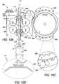
- FIG. 10C this is an exploded view of a portion of the watch mechanism of FIG. 10B , and includes detail concerning the construction of element 1024.
- FIG. 10D this is an enlarged view of another portion of the watch mechanism of FIG. 10B .
- FIG. 10C this is an enlarged view of another portion of the watch mechanism of FIG. 10B .
- 10E is a top view of spring R.
- An idler gear is urged in a wedgeing relationship with spring R. It is appreciated that system 1000 winds when it goes in one direction, and slips in the other direction. Hence, system 1000 manages movement in both directions. Overall, the mechanism is symmetrical around a cylindrical/or rectangular rod. In both directions a clock spring is being wound, so that there is a slipping arrangement and mechanism provided and configured with its various sub-systems transversely so it will wind the watch in both directions.
- Symetrical system 1000 is designed so forces are the same on both sides of the rod 1002. However, there may also be transverse movement or parallel to the axis movement of the rod 1002. An optional flange or other retaining mechanism is also provided so that the flange permits limited side to side side movement of rod 1002. It could be directly attached to the system 1000 or components thereof.
- the bellows system as described herein, in one variant of the invention, is laid on top of or over the system/mechanism 100, and the bellows system or components thereof act against an arm that comes off the rectangular rod. It is appreciated that the sandwiched arrangement of the bellows systems and systems 1000 permit a watch to be more compact. Laying the bellows over the mechanism/system 1000 also make it more compact.
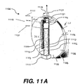
- Sub-system 1100 enables a method of energizing rod 1109 (similar to rod 1002) and the diagram illustrates the axial backwards and forwards movement as indicated by arrow 1115 of rectangular rod 1109 from a maximal position 1117 through a nominal position 1119 to a minimal position 1121 using a sub-system 1100 of the present invention, and displacements in between.
- the minimal position 1121 is obtained when the temperature is between 17C and -20C.
- the nominal position 1119 is obtained when the temperature is at 0.1 C with a delta T of 0.02C.
- the maximal position 1117 is obtained at a temperature range from 32C to 70C.
- the displacement between the maximal position 1117 and the minimal position 1121 is approximately 9 mm, but of course displacements within any desired range are possible.
- the system includes a base 1111, fluid temperature expansion and contraction system 1102, top portion 1104, to which rod 1109 is connected, as well as circular heat transfer conduit 1106 to which base 1111 is connected.
- Fluid temperature expansion and contraction system 1102 is further comprised of a bellows 1103 which is filled with a thermally expanding and contracting fluid or gas 1113 in the interior thereof.
- An optional tubular outer sleeve 1105 around the bellows 1103 is also provided which is matingly and moveably connected to top portion 1104 allowing for movement of the top portion 1104 in relation to the sleeve 1105.
- base 1111 and heat transfer conduit 1106 are constructed from appropriate heat transferring materials such as metals and other thermally conductive materials to obtain the desired movement of rod 1102.
- a thickness of conduit 1106 is 1.3 mm in one variant of the invention with the length from the base 1100 to the nominal position of the middle of top portion 1104 being approximately 32.6 mm.
- the conduit itself has a diameter of 40 mm, but of course can be circular or any other desired three dimensional geometry and dimenions can be used.
- An exemplary diameter of 4.9 mm of system 1100 is provided as indicated by arrow 1125, but other diameters and geometric cross sections can also be used.
- Variouses axial forces as illustrated by arrow 1127 are exerted by the system 1100 as desired depending choice of materials and the like.
- a force of 30 N is generated by the system, but the system can be designed to exert forces in any desired watchmaker range.
- Rod 1109 is contrued to have a rectangular cross section in one variant of the invention, but in other variants of the invention the cross section can have a variety of cross sections, circular, oval, triangular, square, etc.
- Further rod 1109 has a connecting portion 1131 which off-sets and separates the mainbody of rod 1109 from the sleeve 1105 and allows motion of this sub-assembly in relation to the sleeve 1105 and conduit 1106.
- a thermally compressible/expandable fluid is located within bellows 1108.
- a 30 N force is generated.
- the materials from which sub-system is constructed can be varied such that the forces generated by the system are in a desired watchmaker range.
- the invention provides a mechanical sub-system 900, 1000 for driving a function of a time piece.
- the sub-system includes a plurality of gear sub-assemblies ( FIGS. 9A-10E ).
- the gear sub-assemblies are positioned symmetrically on opposite sides of an a axis of a rod.
- the gear sub-assemblies being rotationally engaged with the rod while the rod moves bi-directionally and cyclically in relation to the gear sub-assemblies to obtain rod movement.
- the rod movement is driven by a means for thermal expansion and contraction as a result of a temperature differential.
- the rod movement is in the range of about 1-20 mm in one variant of the invention. It is further appreciated that the rod movement and displacement can be greater than this amount in another variant of the invention.
- the invention further provides for a fluid-mechanical sub-system for driving a function of a user worn time piece ( FIG. 11A , FIG. 11B ).
- the fluid mechanical sub-system 1100 includes a rod 1109, and a fluid-containing bellows-operated main body.
- the rod 1109 is constructed to be off-set from the main body, and the main body is thermally connected to a base 1111.
- the base 1111 is thermally connected to a heat transferring member 1106.
- fluid-mechanical sub-system 1100 further can include one or more second sub-systems 900, 1000 ( FIGS. 9A-10E ).
- the second sub-systems 900, 1000 are constructed to use the forward and backward limited, axial movement of the rod 1109 to actuate the second sub-system(s).
- a mechanical watch can be powered by the liquid expansion generated through an ambient temperature variation (thermal winding system, hereafter TWS).
- TWS ambient temperature variation
- the watch is worn on the wrist (temperature variation from 18 to 33°C during 16 hours.
- the watch is not worn (temperature drop from 31 to 25°C during 8 hours).
- ⁇ T d 15°C*Nb d
- ⁇ T n 6°C.
- the functional requirements of the time piece are: Daily stored energy: E s ⁇ 200 mJ (with the reference being: H1 and H2 barrels), as per the watch maker's specification.
- the max. liquid volume is V r ⁇ 2000 mm 3 or as desired by the watchmaker.
- the transmission requirements are minimal rotation: ⁇ i _min ⁇ 4°.
- the reference liquid is known by the trade name FC-40 and is used in the present invention.
- a reservoir insulated from the body temperature is more sensitive to an environmental temperature drop and provides a better temperature drop conversion (80% instead of 50%).
- the daily cumulated Delta T has a major impact on the effectiveness of the present invention.
- An amount between 113.4°C and 33.4°C (including temperature drops and system thermal inertia compensation) is used based on measurement(s) performed with a data logger.
- an interface with the inverter/barrel is used.
- the conversion of the small system translation is required ( ⁇ 20 ⁇ m) to produce a rotation of 4° is achievable through an epicyclical gearing and/or a spur gears system having an overall dimension compatible with their integration into a wristwatch.
- the play in such systems is large and has to be removed in order to ensure that the translation of 20 ⁇ m is converted into a rotation of at least 4°.
- the design of a low play transmission system is established and tested through a representative demonstrator.
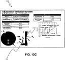
- an extension limitation is shown.
- the extension limitation is based on the buckling of a small diaphragm or membrane 1310 to secure the bellows extension from -20°C to 70°C.
- the required pressure 1312 to start the diaphragm 1310 buckling is verified, and the diaphragm materials are chosen to operate under the desired parameters to secure proper bellows extension 1314.
- the verification of the thermal winding concept functionality is integrated within a wristwatch using a representative demonstrator.
- the fluid-mechanical sub-system also includes a membrane 1310 with the system and components thereof.
- the membrane 1310 is capable of moving system components within a desired operating range.
- the membrane is selected and adapted to function at a temperature range outside of a user, and enables the system to operate.
Landscapes
- Physics & Mathematics (AREA)
- General Physics & Mathematics (AREA)
- Life Sciences & Earth Sciences (AREA)
- Sustainable Development (AREA)
- Engineering & Computer Science (AREA)
- Metallurgy (AREA)
- Micromachines (AREA)
- Electric Clocks (AREA)
- Actuator (AREA)
- Prostheses (AREA)
- Infusion, Injection, And Reservoir Apparatuses (AREA)
Description
- This invention relates to driving system for energizing a device, as defined in the preamble of
claim 1. More particularly, the invention relates to temperature differential driven self-winding timepieces, particularly wristwatches, which are wound in response to change in temperature. - Many, if not all, wrist watches, other than battery powered watches, receive energy for winding a main spring through a main spring barrel arbor from a winding weight or rotor in the watch which rotates in a direction due to movement of the watch wearer's arm. This movement of the wearer's arm produces acceleration of the winding weight or rotor about a pivotal axis. This results in bi-directional rotation of the shaft upon which it is mounted. The bi-directional rotation of this shaft is converted to unidirectional rotation of another shaft, which in turn winds the mainspring. A simple and common mechanism for converting bi-directional rotation of one shaft in a watch to unidirectional rotation of another shaft is known as a Pellaton mechanism. A Pellaton mechanism comprises a lever, which is bifurcated at one end. The bifurcated arms are acted upon by a rotating cam or eccentric pin to produce an eccentric oscillating motion. Spring loaded pawls on the lever engage a ratchet wheel at spaced apart locations on the ratchet wheel causing unidirectional rotation of the ratchet with the oscillating motion of the lever induced by the winding weight or rotor, e.g.
U. S. Patents 2,696,073 and4,174,607 . - Another mechanism for this type of mechanical conversion is known as a wig-wag mechanism. Here, a pinion on a bi-directionally rotatable shaft drives a linearly displaceable wig-wag gear. This gear engages one of two other gears dependent on the direction of rotation of the wig-wag gear. The gear arrangement is organized such that the mainspring barrel will always be driven in a direction to wind the mainspring.
- A thermal energy converting device according to the preamble of
claim 1 is known fromEP 1 101 937 - Self-winding wrist watches generally have a power reserve of about one and one-half to three days. This is also called autonomy. The terms "autonomy" and "power reserve" refer to the time a self winding wrist watch will continue to run if fully wound, but not worn. Various efforts to increase the power reserve of a watch have been undertaken, but still result in the watch losing all power reserve after a period of time of not being worn. Hence, there is a need for a self-winding watch that does not rely on its inherent power reserve derived from motion of a user's arm. The invention solves these and other needs in the art.
- The invention provides a drive system for energizing a device, as defined in
claim 1. This and other objects of the invention are shown in further detail in the drawings, the brief description of the drawings, and detailed specification below. -
-
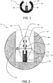
FIG. 1 is a top plan view of a section of a drive system of the invention. -
FIG. 2 is a top plan view of a section of another embodiment of a drive system of the invention. -
FIG. 3A is a front view of a compound bellows mechanism used in the invention. -
FIG. 3B is a perspective view of the compound bellows mechanism used in the invention -
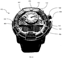
FIG. 4 is a top perspective photograph of a time piece incorporating a drive system of the present invention. -
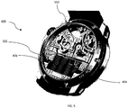
FIG. 5 is a rear perspective photograph of a time piece ofFIG. 4 incorporating a drive system of the present invention. -
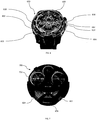
FIG. 6 is a top perspective photograph of a time piece variant incorporating a drive system of the present invention. -
FIG. 7 is a rear top view photograph of a time piece variant ofFIG. 6 incorporating a drive system of the present invention. -
FIG. 8 is an exploded rear perspective view of the time piece variant ofFIG. 4 . -
FIG. 9A is a side perspective view of a toothed gear and gear with soft functional surface sub-system used in the mechanism illustrated inFIG. 9B . -
FIG. 9B is a top view illustration of a sub-system of a watch mechanism of the present invention. -
FIG. 9C is an enlarged view of a portion of the watch mechanism ofFIG. 9B . -
FIG. 9D is a side perspective view of the spring of the invention. -
FIG. 10A is an exploded view of a tooth gear and gear with soft functional surface sub-system used in the mechanism illustrated inFIG. 10B . -
FIG. 10B is a top view illustration of a watch mechanism of the present invention. -
FIG. 10C is an enlarged view of a portion of the watch mechanism ofFIG. 10B . -
FIG. 10D is an enlarged view of another portion of the watch mechanism ofFIG. 10B . -
FIG. 10E is a side perspective view of the spring of the invention. -
FIG. 11A andFIG. 11B are schematics of the T-rod subsystem. -
FIG. 12A - FIG. 12Q show calculations and simulations for designing the drive system of the present invention. -
FIG. 13A - FIG. 13E show extension limitation in the drive system of the present invention. Those skilled in the art will appreciate that elements in the Figures are illustrated for simplicity and clarity and have not necessarily been drawn to scale. For example, dimensions may be exaggerated relative to other elements to help improve understanding of the invention and its embodiments. Furthermore, when the terms 'first', 'second', and the like are used herein, their use is intended for distinguishing between similar elements and not necessarily for describing a sequential or chronological order. Moreover, relative terms like 'front', 'back', 'top' and 'bottom', and the like in the description and/or in the claims are not necessarily used for describing exclusive relative position. Those skilled in the art will therefore understand that such terms may be interchangeable with other terms, and that the embodiments described herein are capable of operating in other orientations than those explicitly illustrated or otherwise described. - The following description is not intended to limit the scope of the invention in any way as they are exemplary in nature, serving to describe the best mode of the invention known the inventors as of the filing date hereof. Consequently, changes may be made in the arrangement and/or function of any of the elements described in the exemplary embodiments disclosed herein.
- The invention relates to a drive system 10 (
FIG. 1 ) for hydro mechanical horological time pieces, e.g. time piece(s) 400, 600 (FIGS. 4-8 ) and sub-systems thereof, as well as other devices described herein. These exemplary time pieces use a liquid 402 in their sub-systems for a functional purpose as is described below, and are constructed from, by way of example, titanium, titanium with shot-peened and satin-finished surfaces that are brushed to a certain color, e.g. pink gold, black DLC-coated titanium, and red gold. Of course, other metal and polymeric materials are also used in the time pieces. The time pieces are sized and dimensioned, by way of example, at about 48 mm in circumference to about 18 mm in thickness or depth, and can include a tapered bezel. Of course, both smaller and larger dimensions can be used such that they are readily worn on a user's forearm or wrist. - The liquid 402, 616 (
FIGS. 4 and6 ) is used to display the hours on a circular tube 826 (FIG. 8 ) around the edge of the dial. A one or plurality ofdrive system 10 piston likedevices 828, 830 (FIG. 8 ) are used in conjunction withbellows dial 408 and are used to push and pull the liquid 402 to show the time on acircular scale 410.Minutes 412 are displayed on a mediumsized sub dial 414 that is optionally set near the center-top 416 of thetime keeping device 400. On the side (right or left) of thetime piece 400, an optionalpower reserve indictor 418 is located for the manual-wing mechanical movement. Some or all of theinterior components time keeping device 400 are viewable through atransparent cover 420 which is located on thetop surface 422 and also optionally a secondtransparent cover 502 may be located on the bottom surface 500 (FIG. 5 ) of thetime keeping device 400. - A
time keeping device 600 is illustrated inFIGS. 6 and 7 in a variant of the invention.Bellows interface 606 that connects the watch mechanisms sub-systems with the fluidic system as described below. Mirroring the pair ofbellows black bridge 608. At the 3 o'clock position is an "H-N-R"crown position indicator 610 and it is counterbalanced by the presence of anotherhand 612 as a component of atemperature indicator 614. Once the watch is worn, this function enables the user to accurately find out when the fluid 616 has reached a functional optimum temperature range.Fluid 616 obeys a set of watchmaking specifications.Fluid 616 is provided in a variety of colours, e.g. red, yellow, green, and provides homogenous resistance to vibrations, shocks and temperature changes, and no alteration in the long term, foolproof water resistance ofdevice 600. When a fluorescein-loadedliquid 616 has done a complete round (rotation) and gets to the 06:00 - 18:00 position, the issuing pump compresses, while thebellows -
Bellows FIG. 8 ). The shape of thebellows minute hand 618 is configured and designed in stages to perfectly fit the structure of the fluidic system and it is designed to jump after 30 minutes to avoid thebellows -
FIG. 7 illustrates the rear 700 of theinternal structure 702 ofdevice 600. In one variant of the invention, the self-windingtimepiece 600 further includes a plurality ofbellows bellows bellows bellows bellows -
FIG. 8 is a rear exploded perspective view of thetime piece 400. Precise micro-litre quantities offluid 402 are used in the closed circuit to provide water resistance. Due to the link between the crown and the liquid 402, the time-setting system is designed in order to avoid the liquid 402 moving around too fast and damaging the meniscus (not shown). Amechanical movement mechanism 822 is situated in theupper part 824 of thewatch 400, and propels a cam, which pushes the piston and activates thebellows - Referring now to
FIG. 1 , the invention concerns adrive system 10 for energizing a device. Thedrive system 10 includes abellows 104 actuateddrive interface 105. The bellows actuateddrive interface 105 provides linear translational forward and backward movement (as shown inFIGS. 1 and 2 ) by fluid expansion and contraction of aheat transfer fluid 107 according to a temperature differential.Fluid 107 is located within arigid reservoir 100. Thereservoir 100 is in fluid contact with bellows 104. Thereservoir 100 is constructed of any suitable material that acts as a heat conduit so that temperature differentials manifested externally of the drive are thermally conveyed to thefluid 107. It is appreciated that bellows 104 is constructed from flexible, elastomeric materials which permit thebellows 104 to move in an axial direction with respect to the bellows main body upon changes in volumes of thefluid 107. An optional mechanical interface connectsbellows 104 torigid reservoir 100.Bellows 104 includes an accordion style body in one variant of the invention as illustrated in the Figures. -
Drive interface 105 can take one of several forms according to the use of the drive system. Anexemplary drive interface 105 is illustrated inFIG. 2 .Rigid reservoir 100 is sized and dimensioned in a variety of geometric configurations. As shown inFIGS. 1 and 2 ,reservoir 100 takes on a substantially circular, tubular configuration (e.g. substantially C-shaped or substantially U-shaped) having the following dimensions which make it suitable to energize a wristwatch as well as the following properties of the fluid within the reservoir: exterior diameter - about 40 mm, interior diameter about 30 mm, thickness about 5 mm, reservoir angle about 270 degrees, reservoir volume 8247 mm3 or there about, surface interface 19.63 mm2 or thereabout (with disc diameter of 5 mm or thereabout), a coefficient of dilation (1/degrees C) - 0.0012 (with 3M Flourinert™ Electronic Liquid FC-40), and an expansion per 1 degree C of 9.90 mm3, a movement at the interface of 0.50 mm, an expansion at 3 degrees C (29.69), and a movement at the interface of 1.51 mm, an expansion per 50 degrees C of 494.80 mm3 - with a movement at the interface of 25.20 mm (from 0 degrees C to +50 degrees C), and an expansion at 90 degrees C of 890.64 mm3 (from -20 degrees C to +70 degrees C) with a movement at the interface of 45.36 mm. It is understood that the system includes a fluid with a high thermal expansion coefficient in another variant of the invention. For this reason, in cases where the device must withstand large temperature variations, the shape and construction of thebellows 104 as well as its stiffness is adapted or modulated, to prevent damage to the device at the temperature extremes. - Referring now to
FIGS. 3A and 3B , as an example, a compound bellows 104' is provided, made up of a large bellows 200 and a smaller bellows 202. Of course, it is understood that the sizes and constructions ofbellows levels gear 112. Where thedevice 10 is exposed to high temperature extremes, thesmall bellows 202 expands until its top 210 abuts against thestop arms 212, which prevent over expansion beyond it's elastic range. It is also appreciated that the bellows can be constructed from materials that provide varied elastic ranges one from another. With increasing temperature, thelarge bellows 200 takes over and expands much less, thereby controlling the total expansion of the system so that it remains within the elastic range of the compound bellows 104' while avoiding excessive expansion that could damage thedevice 10. - Note that the thickness t of the compound bellows 104' may be small compared to the widths w1 and w2 of its components, in order to have a lower profile, enabling the device to be placed within a watch casing.
-
Drive system 10 is used to power a variety of devices which include, by way of further example: a wristwatch, a pocket watch, a timepiece, a medical device, an implantable medical device, a cardiac rhythm management device, a hearing aid, a medical micro-injector, a sensor, and a biometric transmitter. Hence, the invention is not limited to use for energizing a wristwatch in one variant of the invention, but rather has a variety of device applications. - In reference to
FIG. 2 , and by way of further example,drive system 10 is used to energize a timepiece. Thedrive system 10 includes a substantially U-shaped,closed reservoir 100. The U-shaped reservoir includes aninner area 109 which includes thevarious drive interfaces 105 that are used in the invention. Thedrive interface 105 illustrated inFIG. 2 is only shown by way of example. Other exemplary drive interfaces 105 include movement conveying mechanisms such as a cam system, a genouillère system, and a multi-lever system. - A fluid 107 is contained within the
reservoir 100. The fluid 107 within the reservoir 100 (which is rigid and constructed from a rigid, transparent or translucent material) expands or contracts as a function of a temperature differential. Various fluids are used in the invention. By way of example, fluids useful in the device, system and method of the present invention are: noncorrosive, chemically un-reactive, and essentially chemically inert. The fluids are non-explosive, non-flammable and non-toxic to life forms particular humans as through exposure to vapor or liquid through skin contact, inhalation and ingestion. It is useful that the fluids maintain a single phase (e.g. liquid) during operating conditions. Exemplary fluids comprise relatively inert fluorinated organic compounds, preferably those in which all or essentially all of the hydrogen atoms are replaced by fluorine atoms. The prefix "per-fluoro" includes compounds in which all, or essentially all, of the hydrogen atoms are replaced by fluorine atoms. - The fluorinated, inert fluids are one or a mixture of fluoroaliphatic compounds having from about 5 to about 18 carbon atoms or more, and optionally containing one or more catenary heteroatoms, such as divalent oxygen, trivalent nitrogen or hexavalent sulfur. Suitable fluorinated, inert fluids useful in this invention include, for example, perfluoroalkanes or perfluorocycloalkanes, such as, perfluoropentane, perfluorohexane, perfluoroheptane, perfluorooctane, perfluoro-1,2-bis(trifluoromethyl)hexafluorocyclobutane, perfluorotetradecahydrophenanthrene, and perfluorodecalin; perfluoroamines, such as, perfluorotributyl amine, perfluorotriethyl amine, perfluorotriisopropyl amine, perfluorotriamyl amine, perfluoro-N-methyl morpholine, perfluoro-N-ethyl morpholine, and perfluoro-N-isopropyl morpholine; perfluoroethers, such as perfluorobutyl tetrahydrofuran, perfluorodibutyl ether, perfluorobutoxyethoxy formal, perfluorohexyl formal, and perfluorooctylformal; perfluoropolyethers; hydrofluorocarbons, such as pentadecafluorohydroheptane, 1,1,2,2-tetrafluorocyclobutane, 1-trifluoromethyl-1,2,2-trifluorocyclobutane, 2-hydro-3-oxaheptadecafluorooctane. Suitable fluorinated, inert fluids include those commercially available from 3M Company under the trade mark "Fluorinert" and include fluorinated, inert fluids taught in
U.S. Pat. Nos. Re 34,651 ,5,317,805 ,5,300,714 ,5,283,148 ,5,251,802 ,5,205,348 ,5,178,954 ,5,159,527 ,5,141,915 ,5,125,978 ,5,113,860 ,5,104,034 ,5,089,152 ,5,070,606 ,5,030,701 ,5,026,752 ,4,997,032 ,4,981,727 ,4,975,300 ,4,909,806 . Fluoronert fluids include FLOURINERT FC-40, FC-43, FC-5311, FC-70 and FC-5312 having boiling points of 155 degrees C., 174 degrees C., 215 degrees C, 215 degrees C and 215 degrees C, respectively. Most preferred of these is 3M FLUORINERT(tm) FC-40. Of course, it is appreciated that other fluids may also be used in the invention provided they have the properties suitable for expansion and contraction necessary to enable the proper working of thebellows 104 within desired mechanical parameters. -
Bellows 104 is disposed within the U-shape inarea 109 andarea 109 optionally includes a plurality offins 115, e.g. expansion and/or contraction fins. It is appreciated that bellows 104 is constructed from suitable elastomeric material that is compatible withfluid 107.Bellows 104 further includes amechanical interface portion 119, and bellows 104 is in fluid connection withreservoir 100 providing axially motion in response to the expansion or contraction of thefluid 107. In the variant inFIG. 2 of the invention,drive system 10 further comprisesslider 110 and a first half-wheel 112 having a first diameter, in which thebellows 104 transfers the linear movement of thebellows 104 through theslider 110. Asecond wheel 114 that has a second diameter is also provided. Thesecond wheel 114 is driven by the first half-wheel 112. It is appreciated that the diameter difference between first half-wheel 112 andsecond wheel 114 multiplies the movement to provide a multiplied movement. It is also understood that half-wheel 112, andwheel 114 contain teeth appropriately sized and dimensioned to interact with each other. The multiplied movement is used to recharge a spiral spring (not shown) in one variant. In a second variant, the multiplied movement is used to actuate and energize an electrical current generator (not shown). Of course other sub-systems can also be actuated depending on the device thedrive system 10 is used in. - The
drive system 10 further comprises apiston 106 actuated by thebellows 104. Thepiston 106 provides linear forward and/or backward movement as indicated by the arrows inFIG. 2 . Apiston guide 108 controls the axial movement of thepiston 106. While this exemplary configuration of thebellows 104 interface with other mechanical features shown inFIG. 2 , they are suitable for use in a wristwatch and the like, and it is appreciated that other mechanisms (be they electrical/mechanical or eletro-mechanical) can be driven using the drive system of the present invention. - As discussed, the invention also provides self winding timepiece(s) 400, 600. The
timepieces fluid 107 within the reservoir expanding or contracting as a function of a temperature differential, and abellows 104 disposed within the U-shape. The bellows 104 is in fluid connection withreservoir 100 so that thebellows 104 provides axially motion in response to the expansion or contraction of the fluid 107, thus movingpiston 106, and half wheel 112 (which pivots at pivot 113). - It is appreciated that the invention described herein also provides a method of energizing a timepiece within a working temperature differential. The working temperature differential is provided by changes in user body temperature, e.g. as per a circadian rhythm, and changes in ambient external temperature. These changes occur in night and day cycles, due to temperature fronts, between areas exposed to sun and wind and the like. The method includes providing a fluid filled reservoir in fluid connection with a bellows, and providing a temperature differential for expansion or contraction of the fluid within the reservoir and bellows to actuate linear motion of the bellows. As described above with respect to
FIGS. 1 and 2 , it is appreciated that a variable transmission rate system is provided working in concert and actuated by bellows 104. The variable transmission rate system allows the timepiece to withstand a large temperature range differential without destruction of the system, while simultaneously keeping a sufficient transfer rate around the working temperature differential. - Now referring to
FIG. 9A , which is a side perspective view of another variant of tooth gear and gear mechanism andsub-system 900 also illustrated in another variant inFIGS. 10A-10E .FIG. 9B is a top view illustration of a watch mechanism/system 900 of the present invention. The purpose of thesystem 900 is to capture the going back and forth linear movement of therectangular rod T 1002 from a displacement of about 20 microns (of course greater or lesser displacements are also captured depending on the requirements of the watchmaker) to wind a clock spring (not shown) placed in the ratchet G assembly 1022'. The explanation focuses on the right side of the axis (as illustrated inFIG. 10 , but referred to in the description ofFIG. 9B ). The left side mechanism with toothed gear/gear with soft frictional surface sub-systems B 1018 andD 1016 is a mirror image replication of the right side mechanisms A 1032,C 1034, whose aim is to stabilize thesystem 1000. Hence, the gear sub-systems described herein include mirror image sub-systems in relation to the axis of movement ofrod T 1002 - While 4 sub-systems A-D are shown, a smaller or greater number of sub-systems are also used in variants of the invention. The
system 900 also includes a system ofk plates 1009' and 1009". Whenrectangular rod T 1002 is moving in the direction 1081 (through, for example thermal expansion or thermal contraction of the fluid in thebellows 1052 which is connected to piston 1050), gear with soft frictional surface d 1010 (also shown inFIG. 10 B) is driven by friction in the same direction, and is constrained by thespring R 1012. Thevarious gear 1028, 1030 (Aa, Bb, Cc, Dd) combinations rotate as shown in each of the respective arrows for these gear systems. The more it advances, the more the space betweenrectangular rod T 1002 andtoothed gear D 1016 decreases, so the friction betweengear d 1010 andrectangular rod T 1002/toothed gear D 1016 increases.Toothed gear D 1016 is driven as the arrow indicates. Following the gear-trains D 1016,B 1018 and E/e 1020 (Gear sys-subsystem E/e rotates and is in rotational engagement as shown inFIG. 9B , as are the other gear combinations and sub-systems shown) the displacement is amplified and sent to ratchetedgear G 1022. Ratchetedgear G 1022 is retained byH brackets friction system 1027 described in I 1025 inFIG. 10D which is an exploded view of area A. - Now referring to
FIG. 9C (and also inFIG. 10C ), retainingsystems cavities 1053 in whichrollers 1054 rotatably reside along the smooth circumference of gear 1022'. Also included is retainingelement 1056. Friction sub-system 1027 (FIGS. (9A-10E) ) includes a connection system torod 1002, and a bellows system or other system as described herein. Whenrectangular rod T 1002 advances indirection 1082, gear with soft frictionalside surface b 1028 is driven by friction in this direction and drives thedrive train B 1030, e / E, G, as before. When the direction is opposite, gear with soft frictional side surface d 1010 (similarly for the other gear combinations in one variant) dis-engages from D and glides over surfaces ofT 1002 and toothgear system D 1016, and even more as the displacement indirection 1082 increases. Whateverdirection ratchet G 1022 rotates in the direction shown. - Now referring to
FIG. 9A , this is a perspective view of atooth gear 1030 andgear 1029 with softfunctional surface 1028 used in the mechanism and system illustrated inFIG. 9B . It is appreciated thatgear 1030 has two portions thereof, a portion that has a smooth, frictionally engagingcircumferential portion 1031 of a sufficient height to accommodate gear orroller 1028, and atoothed portion 1033 for mated, rotational engagement of the other elements ofsystem 900. It is further appreciated that soft functional surface system gears a, b, c, d are replicated in each of the drive train systems A 1032, B1018,C 1034,D 1016, and include tooth gears A, B, C and D, of which anexemplary gear 1030 is illustrated inFIGS. 9A and10A . - Each respective sub-system has a combination of a respective larger gear, a mating smaller gear, and a spring r, and all sub-systems operate in various rotational relations to one another. For example, sub-assembly large gear A rotating counter-clockwise, sub-assembly large gear C rotates clockwise. For example, sub-assembly large gear D rotating counter-clockwise, sub-assembly large gear B rotates clockwise, while smaller gears rotate as follows: a -clockwise, b-counter clockwise, c- counterclockwise, and d-clockwise. At the same time gear subsystem E/e rotates counterclockwise, while
gear 1022 rotates clockwise. It is appreciated that other rotational variant can also be used in keeping with the invention. - Now referring to
FIG. 9C , this is an enlarged view of a portion of the watch mechanism ofFIG. 9B , and includes detail concerning the construction ofelement 1024, which is further replicated inelement 1026. Whileelements gear 1022 is it appreciated that a single or three or more of such elements are also used in variants of the invention. Now referring toFIG. 9D , this is an enlarged view of another portion of the watch mechanism ofFIG. 10B .FIG. 10E is a top view of spring r or retainingclip r 1028. An idler gear is urged in a relationship withspring r 1028. It is appreciated thatsystem 900 winds when it goes in one direction, and slips in the other direction. Hence,system 900 manages movement in both directions. Overall, the mechanism is symmetrical around a cylindrical/or rectangular rod. In both directions a clock spring is being wound, so that there is a slipping arrangement and mechanism provided and configured with its various sub-systems transversely so it will wind the watch in both directions. - Now referring to
FIG. 10B which is a top view illustration of a watch mechanism/system 1000 of the present invention, the purpose of thesystem 1000 is to capture the going back and forth linear movement of therectangular rod T 1002 from a displacement of about 20 microns (of course greater or lesser displacements are also captured depending on the requirements of the watchmaker) to wind a clock spring (not shown) placed in theratchet 1022. The explanation focuses on the right side of the axis T. The left side mechanism with toothed gear/gear with soft frictional surface systems B and D is a mirror image replication of the right side mechanisms, whose aim is to stabilize thesystem 1000. Thesystem 1000 also includesplate 1009', 1009" (See, also,FIG. 11 , heat transfer conduit 1106). Whenrectangular rod T 1002 is moving in the direction 1081 (through, for example thermal expansion of the fluid in the bellows), gear with softfrictional surface d 1010 is driven by friction in the same direction, constrained by thespring R 1012. The more it advances, the more the space betweenrectangular rod T 1002 andtoothed gear D 1016 decreases, so the friction betweengear d 1010 andrectangular rod T 1002/toothed gear D 1016 increases.Toothed gear D 1016 is driven as the arrow indicates. Following the gear-trains D 1016,B 1018 andE 1020, the displacement is amplified and sent to ratchetedG 1022, which is retained byH brackets friction system 1027 described in I 1025 inFIG. 10D which is an exploded view of areaA. Friction system 1027 includes a connection system torod 1002, and a bellows system or other system as described herein. Whenrectangular rod T 1002 advances indirection 1082, gear with soft frictionalside surface b 1028 is driven by friction in this direction and drives thedrive train B 1030, e / E, G, as before. When the direction is opposite, gear with soft frictionalside surface d 1010 disengages from D & glides over surfaces ofT 1002 and toothgear system D 1034, and even more as the displacement increases. Whateverdirection ratchet G 1022 rotates in the direction shown. Now referring toFIG. 10A , this is an enlarged view of a tooth gear and gear with soft functional surface system used in the mechanism and system illustrated inFIG. 10B . It is appreciated that soft functional surface system gears a, b, c, d are replicated in each of the drive train systems A 1032, B1018,C 1034,D 1016, and include tooth gears A, B, C and D, of which anexemplary gear 1030 is illustrated inFIG. 10A . Now referring toFIG. 10C , this is an exploded view of a portion of the watch mechanism ofFIG. 10B , and includes detail concerning the construction ofelement 1024. Now referring toFIG. 10D , this is an enlarged view of another portion of the watch mechanism ofFIG. 10B .FIG. 10E is a top view of spring R. An idler gear is urged in a wedgeing relationship with spring R. It is appreciated thatsystem 1000 winds when it goes in one direction, and slips in the other direction. Hence,system 1000 manages movement in both directions. Overall, the mechanism is symmetrical around a cylindrical/or rectangular rod. In both directions a clock spring is being wound, so that there is a slipping arrangement and mechanism provided and configured with its various sub-systems transversely so it will wind the watch in both directions. - It is further appreciated that there are alignment problems because the
rod 1002 has to be free and be capable of moving freely, because friction is also being applied to it.Symetrical system 1000 is designed so forces are the same on both sides of therod 1002. However, there may also be transverse movement or parallel to the axis movement of therod 1002. An optional flange or other retaining mechanism is also provided so that the flange permits limited side to side side movement ofrod 1002. It could be directly attached to thesystem 1000 or components thereof. The bellows system as described herein, in one variant of the invention, is laid on top of or over the system/mechanism 100, and the bellows system or components thereof act against an arm that comes off the rectangular rod. It is appreciated that the sandwiched arrangement of the bellows systems andsystems 1000 permit a watch to be more compact. Laying the bellows over the mechanism/system 1000 also make it more compact. - Now referring to
FIG. 11A andFIG. 11B , arod sub-system 1100 is provided.Sub-system 1100 enables a method of energizing rod 1109 (similar to rod 1002) and the diagram illustrates the axial backwards and forwards movement as indicated byarrow 1115 ofrectangular rod 1109 from amaximal position 1117 through anominal position 1119 to aminimal position 1121 using asub-system 1100 of the present invention, and displacements in between. Theminimal position 1121 is obtained when the temperature is between 17C and -20C. Thenominal position 1119 is obtained when the temperature is at 0.1 C with a delta T of 0.02C. Themaximal position 1117 is obtained at a temperature range from 32C to 70C. The displacement between themaximal position 1117 and theminimal position 1121 is approximately 9 mm, but of course displacements within any desired range are possible. The system includes a base 1111, fluid temperature expansion andcontraction system 1102,top portion 1104, to whichrod 1109 is connected, as well as circularheat transfer conduit 1106 to which base 1111 is connected. Fluid temperature expansion andcontraction system 1102 is further comprised of abellows 1103 which is filled with a thermally expanding and contracting fluid orgas 1113 in the interior thereof. An optional tubularouter sleeve 1105 around thebellows 1103 is also provided which is matingly and moveably connected totop portion 1104 allowing for movement of thetop portion 1104 in relation to thesleeve 1105. - It is appreciated that base 1111 and
heat transfer conduit 1106 are constructed from appropriate heat transferring materials such as metals and other thermally conductive materials to obtain the desired movement ofrod 1102. A thickness ofconduit 1106 is 1.3 mm in one variant of the invention with the length from thebase 1100 to the nominal position of the middle oftop portion 1104 being approximately 32.6 mm. The conduit itself has a diameter of 40 mm, but of course can be circular or any other desired three dimensional geometry and dimenions can be used. An exemplary diameter of 4.9 mm ofsystem 1100 is provided as indicated byarrow 1125, but other diameters and geometric cross sections can also be used. Variouses axial forces as illustrated byarrow 1127 are exerted by thesystem 1100 as desired depending choice of materials and the like. In one variant, a force of 30 N is generated by the system, but the system can be designed to exert forces in any desired watchmaker range. Of course, other dimensions and volumes ofelement 1102 are selected depending on the desired displacement ofrod 1109.Rod 1109 is contrued to have a rectangular cross section in one variant of the invention, but in other variants of the invention the cross section can have a variety of cross sections, circular, oval, triangular, square, etc.Further rod 1109 has a connectingportion 1131 which off-sets and separates the mainbody ofrod 1109 from thesleeve 1105 and allows motion of this sub-assembly in relation to thesleeve 1105 andconduit 1106. A thermally compressible/expandable fluid is located within bellows 1108. In one variant, a 30 N force is generated. Of course the materials from which sub-system is constructed can be varied such that the forces generated by the system are in a desired watchmaker range. - As such, the invention provides a
mechanical sub-system FIGS. 9A-10E ). The gear sub-assemblies are positioned symmetrically on opposite sides of an a axis of a rod. The gear sub-assemblies being rotationally engaged with the rod while the rod moves bi-directionally and cyclically in relation to the gear sub-assemblies to obtain rod movement. The rod movement is driven by a means for thermal expansion and contraction as a result of a temperature differential. The rod movement is in the range of about 1-20 mm in one variant of the invention. It is further appreciated that the rod movement and displacement can be greater than this amount in another variant of the invention. - The invention further provides for a fluid-mechanical sub-system for driving a function of a user worn time piece (
FIG. 11A ,FIG. 11B ). The fluidmechanical sub-system 1100 includes arod 1109, and a fluid-containing bellows-operated main body. Therod 1109 is constructed to be off-set from the main body, and the main body is thermally connected to a base 1111. The base 1111 is thermally connected to aheat transferring member 1106. The rod is capable of axial forward and backward movement as indicated byarrow 1105 within a range of positions based upon changes in temperature from aminimal position 1121, through anominal position 1119 to amaximal position 1117 such that therod 1109 only moves within anarea 1135 defined by a surface 1137 of theheat transferring member 1106. It is appreciated that fluid-mechanical sub-system 1100 further can include one or moresecond sub-systems 900, 1000 (FIGS. 9A-10E ). Thesecond sub-systems rod 1109 to actuate the second sub-system(s). - It should be appreciated that the particular implementations shown and herein described are representative of the invention and its best mode and are not intended to limit the scope of the present invention in any way.
- As is appreciated, a mechanical watch can be powered by the liquid expansion generated through an ambient temperature variation (thermal winding system, hereafter TWS). During the day, the watch is worn on the wrist (temperature variation from 18 to 33°C during 16 hours. During the night the watch is not worn (temperature drop from 31 to 25°C during 8 hours). During the day: ΔTd = 15°C*Nbd and during the night: ΔTn = 6°C. The total temperature variation is ΔT = ΔTd + ΔTn = 15°C*Nbd + 6° with Nbd to be defined at watchmaker's desired specification. The functional requirements of the time piece are: Daily stored energy: Es ≈ 200 mJ (with the reference being: H1 and H2 barrels), as per the watch maker's specification. The max. liquid volume is Vr ≈ 2000 mm3 or as desired by the watchmaker. The transmission requirements are minimal rotation: αi_min ≈ 4°. The maximal force: Fi_max≈ 15 N in one variant of the invention. The temperature requirements are as follows in one variant of the invention: working temperature range: ΔTw = 15°C (from 18°C to 33°C) and the safe temperature range is: ΔTs = 90°C (from - 20°C to 70°C). The reference liquid is known by the trade name FC-40 and is used in the present invention. It has a density of ρl = 1855 kg/m3, a specific heat of Cl = 1100 J/(kg*°C), and a coefficient of expansion of αl = 0.0012 1/°C. Other fluids can also be used with similar properties. The dimensions of the TWS active surface are Sp = 12.6 mm2 (r = 2 mm), and include a required displacement from 18°C to 33°C : xΔTW ≈3 mm, a required displacement from -20°C to 70°C of
- xΔTS ≈ 18 mm, and a required force of F = f(ΔT). Based on this calculation two observations are made:
- 1. The daily cumulated ΔT is evaluated to define the force required on the system. A value close to 50°C is used to limit the force applied on the mechanism.
- 2. The required safe displacement is large and not achievable by a standard metallic bellows, so other bellows materials are used, and a system to secure the extension is implemented, as shown in
Figures 12A - 12Q andFigures 13A - 13E , respectively.
- Based on these simulations, a reservoir insulated from the body temperature is more sensitive to an environmental temperature drop and provides a better temperature drop conversion (80% instead of 50%).
- Based on these calculations, the following observations are made. The required safe displacement is large and not achievable by a standard metallic bellows, and thus other materials for the bellows are used such as polymeric materials. A system to secure the extension is also implemented. The required minimal displacement of 20 µm is sufficient to generate the rotation of the inverter and the barrel preload. Of course, other displacements are also used herein according to the calculations, and material requirements conforming at least in part to
Figures 13A - 13E . The disk ofFig. 13A' is placed at the right side of the element inFig. 13A in a of the invention.Figures 13C - 13E illustrate one version of the invention which is particularly effective for accomplishing the objectives of the invention. The daily cumulated Delta T has a major impact on the effectiveness of the present invention. A cumulated ΔT of 50°C is required to ensure suitable force inside the mechanism (F = 20.3 N). An amount between 113.4°C and 33.4°C (including temperature drops and system thermal inertia compensation) is used based on measurement(s) performed with a data logger. - In one variant of the invention, an interface with the inverter/barrel is used. The conversion of the small system translation is required (∼20 µm) to produce a rotation of 4° is achievable through an epicyclical gearing and/or a spur gears system having an overall dimension compatible with their integration into a wristwatch. The play in such systems is large and has to be removed in order to ensure that the translation of 20 µm is converted into a rotation of at least 4°. The design of a low play transmission system is established and tested through a representative demonstrator.
- Now referring to
FIG. 13A - FIG. 13C , an extension limitation is shown. The extension limitation is based on the buckling of a small diaphragm ormembrane 1310 to secure the bellows extension from -20°C to 70°C. In particular, the requiredpressure 1312 to start thediaphragm 1310 buckling is verified, and the diaphragm materials are chosen to operate under the desired parameters to secureproper bellows extension 1314. The verification of the thermal winding concept functionality is integrated within a wristwatch using a representative demonstrator. In another variant of the invention, it is appreciated that the fluid-mechanical sub-system also includes amembrane 1310 with the system and components thereof. Themembrane 1310 is capable of moving system components within a desired operating range. The membrane is selected and adapted to function at a temperature range outside of a user, and enables the system to operate.
Claims (5)
- A drive system (10) for energizing a device, comprising: a bellows (104, 104', 1103) actuated drive, the bellows actuated drive being configured to provide linear forward and backward movement (1115) by fluid (107, 1113) expansion and contraction of a fluid within a reservoir (100) according to a temperature differential, and the reservoir being in fluid communication with the bellows, characterized in that the drive system comprises a buckling diaphragm (1310) in fluid communication with the reservoir, the diaphragm being sized and dimensioned to provide the bellows actuated drive with an extension limitation (1308).
- The drive system (10) of claim 1 in which the device is selected from the group consisting of a timepiece, a medical device, an implantable medical device, a cardiac rhythm management device, a hearing aid, a medical micro-injector, a sensor, and a biometric transmitter.
- The drive system (10) of claim 1 further comprising a movement conveying mechanism, the movement conveying mechanism selected from the group consisting of a cam system, a genouillère system, a half moon gear system, and a multi-lever system.
- The drive system (10) of claim 3 in which the movement conveying mechanism further comprises a piston (106) configured to be actuated by the bellows (104, 104', 1103) actuated drive, the piston (106) being configured to provide axial, linear forward and/or backward movement.
- The drive system (10) of claim 4 further comprising a piston guide (108) configured to control the axial movement of the piston (106).
Applications Claiming Priority (2)
| Application Number | Priority Date | Filing Date | Title |
|---|---|---|---|
| US201361787727P | 2013-03-15 | 2013-03-15 | |
| PCT/IB2014/000373 WO2014140779A2 (en) | 2013-03-15 | 2014-03-17 | Temperature driven winding system |
Publications (3)
| Publication Number | Publication Date |
|---|---|
| EP2972596A2 EP2972596A2 (en) | 2016-01-20 |
| EP2972596B1 true EP2972596B1 (en) | 2018-01-31 |
| EP2972596B8 EP2972596B8 (en) | 2018-04-11 |
Family
ID=50928146
Family Applications (1)
| Application Number | Title | Priority Date | Filing Date |
|---|---|---|---|
| EP14729432.6A Active EP2972596B8 (en) | 2013-03-15 | 2014-03-17 | Temperature driven drive system |
Country Status (5)
| Country | Link |
|---|---|
| US (1) | US10031481B2 (en) |
| EP (1) | EP2972596B8 (en) |
| JP (1) | JP6457407B2 (en) |
| CN (1) | CN105283812B (en) |
| WO (1) | WO2014140779A2 (en) |
Cited By (1)
| Publication number | Priority date | Publication date | Assignee | Title |
|---|---|---|---|---|
| US11739243B2 (en) | 2018-12-21 | 2023-08-29 | Honeywell International Inc. | Azeotrope or azeotrope-like compositions of 1,2,2-trifluoro-1-trifluoromethylcyclobutane (TFMCB) and applications thereof |
Families Citing this family (9)
| Publication number | Priority date | Publication date | Assignee | Title |
|---|---|---|---|---|
| USD789802S1 (en) * | 2011-10-14 | 2017-06-20 | Hyt Sa | Wrist watch |
| USD751421S1 (en) * | 2013-03-15 | 2016-03-15 | Hyt Sa | Wrist watch |
| US10481555B2 (en) * | 2015-01-07 | 2019-11-19 | Preciflex Sa | System and method of force displacement insensitive to temperature changes |
| CN107636540B (en) * | 2015-04-07 | 2021-04-20 | 普雷斯弗雷克斯股份公司 | pointing device |
| WO2018055445A1 (en) * | 2016-09-20 | 2018-03-29 | Preciflex Sa | Dynamic fluidic jewelry |
| TWI623827B (en) * | 2017-01-05 | 2018-05-11 | I-Shou University | An adjustment method of an air clock and a detection system for use with the adjustment method |
| JP1623534S (en) * | 2017-12-20 | 2019-02-04 | ||
| US20210034014A1 (en) * | 2018-02-09 | 2021-02-04 | Montre Liquide Ag | Submerged mechanical timepiece |
| US12006919B2 (en) | 2018-09-13 | 2024-06-11 | Preciflex Sa | Energy harvesting with fluids |
Family Cites Families (42)
| Publication number | Priority date | Publication date | Assignee | Title |
|---|---|---|---|---|
| CH238871A (en) | 1944-02-28 | 1945-08-31 | Imhof Arthur | Winding device. |
| FR1096666A (en) | 1950-01-04 | 1955-06-23 | Automatic winding mechanism for watches | |
| US2749700A (en) * | 1953-11-04 | 1956-06-12 | Seligman Hans | Hydraulic clock |
| DE1892175U (en) | 1964-01-29 | 1964-04-30 | Kienzle Uhrenfabriken Ag | LOUDSPEAKER FOR ALARM CLOCK. |
| CH465510A (en) | 1966-08-04 | 1968-12-31 | Centre Electron Horloger | Method and device for displaying electrical time signals from a clock |
| US4067381A (en) * | 1975-07-16 | 1978-01-10 | United Aircraft Products, Inc. | Temperature compensated quantity indicator |
| JPS52157854U (en) | 1976-05-25 | 1977-11-30 | ||
| US4174607A (en) | 1978-12-13 | 1979-11-20 | Timex Corporation | Mechanism for self-wind watches |
| JPS58106185A (en) | 1981-12-17 | 1983-06-24 | Katsuyoshi Egawa | Device for obtaining rotating power from thermal source |
| CN85202423U (en) * | 1985-06-21 | 1986-06-04 | 潘忠勋 | Regulating pressure indicator for liquified gas |
| US4981727A (en) | 1986-08-29 | 1991-01-01 | Minnesota Mining And Manufacturing Company | Polyfluoropolyethers having pendant perfluoroalkoxy groups |
| US5026752A (en) | 1987-04-03 | 1991-06-25 | Minnesota Mining And Manufacturing Company | Amorphous-polypropylene-based hot melt adhesive |
| US4997032A (en) | 1987-09-25 | 1991-03-05 | Minnesota Mining And Manufacturing Company | Thermal transfer bag |
| US4975300A (en) | 1987-12-31 | 1990-12-04 | Minnesota Mining And Manufacturing Company | Method for curing an organic coating using condensation heating and radiation energy |
| US4909806A (en) | 1987-12-31 | 1990-03-20 | Minnesota Mining And Manufacturing Company | Fluorine- and chromophore-containing polymer |
| US5030701A (en) | 1987-12-31 | 1991-07-09 | Minnesota Mining And Manufacturing Company | Fluorine- and chromophore-containing polymer |
| US4871623A (en) | 1988-02-19 | 1989-10-03 | Minnesota Mining And Manufacturing Company | Sheet-member containing a plurality of elongated enclosed electrodeposited channels and method |
| US5070606A (en) | 1988-07-25 | 1991-12-10 | Minnesota Mining And Manufacturing Company | Method for producing a sheet member containing at least one enclosed channel |
| GB8916739D0 (en) | 1989-07-21 | 1989-09-06 | Minnesota Mining & Mfg | Protective layer for magnetic recording media |
| CA2026165A1 (en) | 1989-10-19 | 1991-04-20 | John C. Hansen | Perfluoro-n,n,n',n'-tetrapropyldiaminopropane and use thereof in vapor phase heating |
| US5300714A (en) | 1990-05-18 | 1994-04-05 | Minnesota Mining And Manufacturing Company | Method of purifying saturated fluoroperhalocarbon liquids |
| US5141915A (en) | 1991-02-25 | 1992-08-25 | Minnesota Mining And Manufacturing Company | Dye thermal transfer sheet with anti-stick coating |
| US5113860A (en) | 1991-03-15 | 1992-05-19 | Minnesota Mining And Manufacturing Company | Non-invasive transmucosal drug level monitoring method |
| US5089152A (en) | 1991-04-19 | 1992-02-18 | Minnesota Mining And Manufacturing Company | Water displacement composition |
| US5125978A (en) | 1991-04-19 | 1992-06-30 | Minnesota Mining And Manufacturing Company | Water displacement composition and a method of use |
| US5251802A (en) | 1991-04-25 | 1993-10-12 | Minnesota Mining And Manufacturing Company | Abrasive article and processes for producing it |
| US5205348A (en) | 1991-05-31 | 1993-04-27 | Minnesota Mining And Manufacturing Company | Semi-rigid heat transfer devices |
| US5159527A (en) | 1991-12-05 | 1992-10-27 | Minnesota Mining And Manufacturing Company | Dielectric liquids |
| US5317805A (en) | 1992-04-28 | 1994-06-07 | Minnesota Mining And Manufacturing Company | Method of making microchanneled heat exchangers utilizing sacrificial cores |
| US5283148A (en) | 1992-09-18 | 1994-02-01 | Minnesota Mining And Manufacturing Company | Liquid toners for use with perfluorinated solvents |
| US6427444B1 (en) * | 1999-05-26 | 2002-08-06 | Seiko Epson Corporation | Method and device for converting thermal energy and device with the thermal energy converting device |
| JP2004104994A (en) * | 1999-05-26 | 2004-04-02 | Seiko Epson Corp | Equipment with thermal energy converter |
| EP1136698A1 (en) * | 2000-03-17 | 2001-09-26 | Seiko Epson Corporation | Temperature difference drive unit, and electric device, timepiece and light electrical appliance having the same |
| JP2001329945A (en) * | 2000-03-17 | 2001-11-30 | Seiko Epson Corp | Temperature difference drive device and electronic device having the same |
| US7245561B2 (en) * | 2001-02-03 | 2007-07-17 | James David Coleman | Water feature |
| JP2003120514A (en) * | 2001-10-05 | 2003-04-23 | Seiko Epson Corp | Thermal energy supply device to equipment having thermal energy conversion device |
| US7616528B2 (en) * | 2004-12-15 | 2009-11-10 | Meadows Michael E | Linear fluid timepiece |
| JP2010533848A (en) * | 2007-07-17 | 2010-10-28 | クレアリュクス・ソシエテ・アノニム | Clock mechanism and clock |
| US8995237B2 (en) * | 2009-08-21 | 2015-03-31 | Preciflex Sa | Fluid indicator |
| EP2469350A1 (en) * | 2010-12-21 | 2012-06-27 | Association Suisse pour la Recherche Horlogère | Pneumatic winding mechanism for a timepiece comprising a source of mechanical energy |
| CN103998995B (en) * | 2011-12-08 | 2016-12-28 | 普雷斯弗雷克斯股份公司 | Low volume precise corrugated pipe |
| WO2015028870A2 (en) * | 2013-08-26 | 2015-03-05 | Preciflex Sa | Energy storage and release device using elastic reservoirs, and methods and timepieces related thereto |
-
2014
- 2014-03-17 CN CN201480015594.1A patent/CN105283812B/en active Active
- 2014-03-17 JP JP2015562363A patent/JP6457407B2/en active Active
- 2014-03-17 WO PCT/IB2014/000373 patent/WO2014140779A2/en not_active Ceased
- 2014-03-17 EP EP14729432.6A patent/EP2972596B8/en active Active
- 2014-03-17 US US14/776,790 patent/US10031481B2/en active Active
Cited By (1)
| Publication number | Priority date | Publication date | Assignee | Title |
|---|---|---|---|---|
| US11739243B2 (en) | 2018-12-21 | 2023-08-29 | Honeywell International Inc. | Azeotrope or azeotrope-like compositions of 1,2,2-trifluoro-1-trifluoromethylcyclobutane (TFMCB) and applications thereof |
Also Published As
| Publication number | Publication date |
|---|---|
| JP6457407B2 (en) | 2019-01-30 |
| EP2972596B8 (en) | 2018-04-11 |
| WO2014140779A4 (en) | 2016-03-03 |
| WO2014140779A2 (en) | 2014-09-18 |
| JP2016518583A (en) | 2016-06-23 |
| CN105283812B (en) | 2018-01-30 |
| WO2014140779A3 (en) | 2015-12-23 |
| CN105283812A (en) | 2016-01-27 |
| EP2972596A2 (en) | 2016-01-20 |
| US10031481B2 (en) | 2018-07-24 |
| US20160033936A1 (en) | 2016-02-04 |
Similar Documents
| Publication | Publication Date | Title |
|---|---|---|
| US10031481B2 (en) | Temperature driven winding system | |
| CN1672102B (en) | watch movement | |
| US20080007141A1 (en) | Drive unit for medical devices | |
| CN102656526B (en) | Fluid visual indicator | |
| JP2016518583A5 (en) | ||
| US9448536B1 (en) | Self-winding mechanical watch with activity tracking | |
| EP2757680B1 (en) | Thermal power generation portable device and power generation control method for thermal power generation portable device | |
| JPH05506594A (en) | Fixed pressure recessed pump reservoir | |
| JP6449619B2 (en) | Holding index device for watches | |
| CN112771270B (en) | Harvesting energy using fluids | |
| CN105404130A (en) | Constant Force Mechanism, Movement And Timepiece | |
| ES2744586T3 (en) | Clockwork mechanism with extended power reserve | |
| ES2423285T3 (en) | Clutch release mechanism for clockwork, and clock movement comprising this device | |
| JP5320368B2 (en) | clock | |
| Patel et al. | Modeling and analysis of an atmospheric driven Atmos clock with mechanical escapement control | |
| JP6085996B2 (en) | Bands and watches | |
| CN209044307U (en) | Watch power reserve indicator structure | |
| CN105593768A (en) | Energy storage and release device using elastic reservoirs, and methods and timepieces related thereto | |
| EP1657604A2 (en) | Timepiece with state-of-winding indicator mechanism | |
| US12578684B2 (en) | Visual indicator and fluid dispenser | |
| JP2023025662A (en) | Timer mechanism indicating maximum value of physical variable to be measured, and timer including such mechanism | |
| JP2021513660A (en) | Immersion machine clock | |
| EP3665533A1 (en) | Submerged mechanical timepiece | |
| US3286454A (en) | Gas spring | |
| US20220062531A1 (en) | Mechanically wound infusion pump |
Legal Events
| Date | Code | Title | Description |
|---|---|---|---|
| PUAI | Public reference made under article 153(3) epc to a published international application that has entered the european phase |
Free format text: ORIGINAL CODE: 0009012 |
|
| 17P | Request for examination filed |
Effective date: 20151013 |
|
| AK | Designated contracting states |
Kind code of ref document: A2 Designated state(s): AL AT BE BG CH CY CZ DE DK EE ES FI FR GB GR HR HU IE IS IT LI LT LU LV MC MK MT NL NO PL PT RO RS SE SI SK SM TR |
|
| AX | Request for extension of the european patent |
Extension state: BA ME |
|
| R17D | Deferred search report published (corrected) |
Effective date: 20151223 |
|
| RIN1 | Information on inventor provided before grant (corrected) |
Inventor name: RUFFIEUX, YVES Inventor name: RENAUD, DOMINIQUE Inventor name: VOUILLAMOZ, LUCIEN Inventor name: ROHNER, JOHANN Inventor name: JACCARD, ALAIN |
|
| DAX | Request for extension of the european patent (deleted) | ||
| 17Q | First examination report despatched |
Effective date: 20161219 |
|
| GRAP | Despatch of communication of intention to grant a patent |
Free format text: ORIGINAL CODE: EPIDOSNIGR1 |
|
| INTG | Intention to grant announced |
Effective date: 20170802 |
|
| GRAS | Grant fee paid |
Free format text: ORIGINAL CODE: EPIDOSNIGR3 |
|
| GRAA | (expected) grant |
Free format text: ORIGINAL CODE: 0009210 |
|
| AK | Designated contracting states |
Kind code of ref document: B1 Designated state(s): AL AT BE BG CH CY CZ DE DK EE ES FI FR GB GR HR HU IE IS IT LI LT LU LV MC MK MT NL NO PL PT RO RS SE SI SK SM TR |
|
| REG | Reference to a national code |
Ref country code: GB Ref legal event code: FG4D Ref country code: CH Ref legal event code: EP |
|
| REG | Reference to a national code |
Ref country code: AT Ref legal event code: REF Ref document number: 967920 Country of ref document: AT Kind code of ref document: T Effective date: 20180215 |
|
| REG | Reference to a national code |
Ref country code: IE Ref legal event code: FG4D |
|
| REG | Reference to a national code |
Ref country code: DE Ref legal event code: R096 Ref document number: 602014020401 Country of ref document: DE |
|
| REG | Reference to a national code |
Ref country code: CH Ref legal event code: NV Representative=s name: DA VINCI PARTNERS LLC, CH Ref country code: CH Ref legal event code: PCOW Free format text: NEW ADDRESS: RUE DE PREBARREAU 17, 2000 NEUCHATEL (CH) |
|
| RAP2 | Party data changed (patent owner data changed or rights of a patent transferred) |
Owner name: PRECIFLEX SA |
|
| REG | Reference to a national code |
Ref country code: FR Ref legal event code: PLFP Year of fee payment: 5 |
|
| REG | Reference to a national code |
Ref country code: NL Ref legal event code: MP Effective date: 20180131 |
|
| REG | Reference to a national code |
Ref country code: LT Ref legal event code: MG4D |
|
| REG | Reference to a national code |
Ref country code: AT Ref legal event code: MK05 Ref document number: 967920 Country of ref document: AT Kind code of ref document: T Effective date: 20180131 |
|
| PG25 | Lapsed in a contracting state [announced via postgrant information from national office to epo] |
Ref country code: NO Free format text: LAPSE BECAUSE OF FAILURE TO SUBMIT A TRANSLATION OF THE DESCRIPTION OR TO PAY THE FEE WITHIN THE PRESCRIBED TIME-LIMIT Effective date: 20180430 Ref country code: NL Free format text: LAPSE BECAUSE OF FAILURE TO SUBMIT A TRANSLATION OF THE DESCRIPTION OR TO PAY THE FEE WITHIN THE PRESCRIBED TIME-LIMIT Effective date: 20180131 Ref country code: HR Free format text: LAPSE BECAUSE OF FAILURE TO SUBMIT A TRANSLATION OF THE DESCRIPTION OR TO PAY THE FEE WITHIN THE PRESCRIBED TIME-LIMIT Effective date: 20180131 Ref country code: LT Free format text: LAPSE BECAUSE OF FAILURE TO SUBMIT A TRANSLATION OF THE DESCRIPTION OR TO PAY THE FEE WITHIN THE PRESCRIBED TIME-LIMIT Effective date: 20180131 Ref country code: ES Free format text: LAPSE BECAUSE OF FAILURE TO SUBMIT A TRANSLATION OF THE DESCRIPTION OR TO PAY THE FEE WITHIN THE PRESCRIBED TIME-LIMIT Effective date: 20180131 Ref country code: FI Free format text: LAPSE BECAUSE OF FAILURE TO SUBMIT A TRANSLATION OF THE DESCRIPTION OR TO PAY THE FEE WITHIN THE PRESCRIBED TIME-LIMIT Effective date: 20180131 |
|
| PG25 | Lapsed in a contracting state [announced via postgrant information from national office to epo] |
Ref country code: GR Free format text: LAPSE BECAUSE OF FAILURE TO SUBMIT A TRANSLATION OF THE DESCRIPTION OR TO PAY THE FEE WITHIN THE PRESCRIBED TIME-LIMIT Effective date: 20180501 Ref country code: AT Free format text: LAPSE BECAUSE OF FAILURE TO SUBMIT A TRANSLATION OF THE DESCRIPTION OR TO PAY THE FEE WITHIN THE PRESCRIBED TIME-LIMIT Effective date: 20180131 Ref country code: RS Free format text: LAPSE BECAUSE OF FAILURE TO SUBMIT A TRANSLATION OF THE DESCRIPTION OR TO PAY THE FEE WITHIN THE PRESCRIBED TIME-LIMIT Effective date: 20180131 Ref country code: PL Free format text: LAPSE BECAUSE OF FAILURE TO SUBMIT A TRANSLATION OF THE DESCRIPTION OR TO PAY THE FEE WITHIN THE PRESCRIBED TIME-LIMIT Effective date: 20180131 Ref country code: IS Free format text: LAPSE BECAUSE OF FAILURE TO SUBMIT A TRANSLATION OF THE DESCRIPTION OR TO PAY THE FEE WITHIN THE PRESCRIBED TIME-LIMIT Effective date: 20180531 Ref country code: LV Free format text: LAPSE BECAUSE OF FAILURE TO SUBMIT A TRANSLATION OF THE DESCRIPTION OR TO PAY THE FEE WITHIN THE PRESCRIBED TIME-LIMIT Effective date: 20180131 Ref country code: BG Free format text: LAPSE BECAUSE OF FAILURE TO SUBMIT A TRANSLATION OF THE DESCRIPTION OR TO PAY THE FEE WITHIN THE PRESCRIBED TIME-LIMIT Effective date: 20180430 Ref country code: SE Free format text: LAPSE BECAUSE OF FAILURE TO SUBMIT A TRANSLATION OF THE DESCRIPTION OR TO PAY THE FEE WITHIN THE PRESCRIBED TIME-LIMIT Effective date: 20180131 |
|
| PG25 | Lapsed in a contracting state [announced via postgrant information from national office to epo] |
Ref country code: EE Free format text: LAPSE BECAUSE OF FAILURE TO SUBMIT A TRANSLATION OF THE DESCRIPTION OR TO PAY THE FEE WITHIN THE PRESCRIBED TIME-LIMIT Effective date: 20180131 Ref country code: AL Free format text: LAPSE BECAUSE OF FAILURE TO SUBMIT A TRANSLATION OF THE DESCRIPTION OR TO PAY THE FEE WITHIN THE PRESCRIBED TIME-LIMIT Effective date: 20180131 Ref country code: RO Free format text: LAPSE BECAUSE OF FAILURE TO SUBMIT A TRANSLATION OF THE DESCRIPTION OR TO PAY THE FEE WITHIN THE PRESCRIBED TIME-LIMIT Effective date: 20180131 Ref country code: IT Free format text: LAPSE BECAUSE OF FAILURE TO SUBMIT A TRANSLATION OF THE DESCRIPTION OR TO PAY THE FEE WITHIN THE PRESCRIBED TIME-LIMIT Effective date: 20180131 |
|
| REG | Reference to a national code |
Ref country code: DE Ref legal event code: R097 Ref document number: 602014020401 Country of ref document: DE |
|
| PG25 | Lapsed in a contracting state [announced via postgrant information from national office to epo] |
Ref country code: MC Free format text: LAPSE BECAUSE OF FAILURE TO SUBMIT A TRANSLATION OF THE DESCRIPTION OR TO PAY THE FEE WITHIN THE PRESCRIBED TIME-LIMIT Effective date: 20180131 Ref country code: CZ Free format text: LAPSE BECAUSE OF FAILURE TO SUBMIT A TRANSLATION OF THE DESCRIPTION OR TO PAY THE FEE WITHIN THE PRESCRIBED TIME-LIMIT Effective date: 20180131 Ref country code: DK Free format text: LAPSE BECAUSE OF FAILURE TO SUBMIT A TRANSLATION OF THE DESCRIPTION OR TO PAY THE FEE WITHIN THE PRESCRIBED TIME-LIMIT Effective date: 20180131 Ref country code: SM Free format text: LAPSE BECAUSE OF FAILURE TO SUBMIT A TRANSLATION OF THE DESCRIPTION OR TO PAY THE FEE WITHIN THE PRESCRIBED TIME-LIMIT Effective date: 20180131 Ref country code: SK Free format text: LAPSE BECAUSE OF FAILURE TO SUBMIT A TRANSLATION OF THE DESCRIPTION OR TO PAY THE FEE WITHIN THE PRESCRIBED TIME-LIMIT Effective date: 20180131 |
|
| PLBE | No opposition filed within time limit |
Free format text: ORIGINAL CODE: 0009261 |
|
| STAA | Information on the status of an ep patent application or granted ep patent |
Free format text: STATUS: NO OPPOSITION FILED WITHIN TIME LIMIT |
|
| REG | Reference to a national code |
Ref country code: BE Ref legal event code: MM Effective date: 20180331 |
|
| REG | Reference to a national code |
Ref country code: IE Ref legal event code: MM4A |
|
| PG25 | Lapsed in a contracting state [announced via postgrant information from national office to epo] |
Ref country code: LU Free format text: LAPSE BECAUSE OF NON-PAYMENT OF DUE FEES Effective date: 20180317 |
|
| 26N | No opposition filed |
Effective date: 20181102 |
|
| PG25 | Lapsed in a contracting state [announced via postgrant information from national office to epo] |
Ref country code: IE Free format text: LAPSE BECAUSE OF NON-PAYMENT OF DUE FEES Effective date: 20180317 |
|
| PG25 | Lapsed in a contracting state [announced via postgrant information from national office to epo] |
Ref country code: SI Free format text: LAPSE BECAUSE OF FAILURE TO SUBMIT A TRANSLATION OF THE DESCRIPTION OR TO PAY THE FEE WITHIN THE PRESCRIBED TIME-LIMIT Effective date: 20180131 Ref country code: BE Free format text: LAPSE BECAUSE OF NON-PAYMENT OF DUE FEES Effective date: 20180331 |
|
| PG25 | Lapsed in a contracting state [announced via postgrant information from national office to epo] |
Ref country code: MT Free format text: LAPSE BECAUSE OF NON-PAYMENT OF DUE FEES Effective date: 20180317 |
|
| PG25 | Lapsed in a contracting state [announced via postgrant information from national office to epo] |
Ref country code: TR Free format text: LAPSE BECAUSE OF FAILURE TO SUBMIT A TRANSLATION OF THE DESCRIPTION OR TO PAY THE FEE WITHIN THE PRESCRIBED TIME-LIMIT Effective date: 20180131 |
|
| PG25 | Lapsed in a contracting state [announced via postgrant information from national office to epo] |
Ref country code: PT Free format text: LAPSE BECAUSE OF FAILURE TO SUBMIT A TRANSLATION OF THE DESCRIPTION OR TO PAY THE FEE WITHIN THE PRESCRIBED TIME-LIMIT Effective date: 20180131 |
|
| PG25 | Lapsed in a contracting state [announced via postgrant information from national office to epo] |
Ref country code: CY Free format text: LAPSE BECAUSE OF FAILURE TO SUBMIT A TRANSLATION OF THE DESCRIPTION OR TO PAY THE FEE WITHIN THE PRESCRIBED TIME-LIMIT Effective date: 20180131 Ref country code: HU Free format text: LAPSE BECAUSE OF FAILURE TO SUBMIT A TRANSLATION OF THE DESCRIPTION OR TO PAY THE FEE WITHIN THE PRESCRIBED TIME-LIMIT; INVALID AB INITIO Effective date: 20140317 Ref country code: MK Free format text: LAPSE BECAUSE OF NON-PAYMENT OF DUE FEES Effective date: 20180131 |
|
| P01 | Opt-out of the competence of the unified patent court (upc) registered |
Effective date: 20230524 |
|
| REG | Reference to a national code |
Ref country code: DE Ref legal event code: R082 Ref document number: 602014020401 Country of ref document: DE Representative=s name: SONNENBERG HARRISON PARTNERSCHAFT MBB PATENT- , DE |
|
| PGFP | Annual fee paid to national office [announced via postgrant information from national office to epo] |
Ref country code: CH Payment date: 20250401 Year of fee payment: 12 |
|
| REG | Reference to a national code |
Ref country code: CH Ref legal event code: R17 Free format text: ST27 STATUS EVENT CODE: U-0-0-R10-R17 (AS PROVIDED BY THE NATIONAL OFFICE) Effective date: 20260327 |
|
| REG | Reference to a national code |
Ref country code: CH Ref legal event code: U11 Free format text: ST27 STATUS EVENT CODE: U-0-0-U10-U11 (AS PROVIDED BY THE NATIONAL OFFICE) Effective date: 20260401 |
|
| PGFP | Annual fee paid to national office [announced via postgrant information from national office to epo] |
Ref country code: GB Payment date: 20260327 Year of fee payment: 13 |
|
| PGFP | Annual fee paid to national office [announced via postgrant information from national office to epo] |
Ref country code: DE Payment date: 20260327 Year of fee payment: 13 |
|
| PGFP | Annual fee paid to national office [announced via postgrant information from national office to epo] |
Ref country code: FR Payment date: 20260325 Year of fee payment: 13 |