EP2972077B1 - Datum transfer apparatus and method for inspecting coated components - Google Patents
Datum transfer apparatus and method for inspecting coated components Download PDFInfo
- Publication number
- EP2972077B1 EP2972077B1 EP13877533.3A EP13877533A EP2972077B1 EP 2972077 B1 EP2972077 B1 EP 2972077B1 EP 13877533 A EP13877533 A EP 13877533A EP 2972077 B1 EP2972077 B1 EP 2972077B1
- Authority
- EP
- European Patent Office
- Prior art keywords
- datum
- coated state
- points
- airfoil
- component
- Prior art date
- Legal status (The legal status is an assumption and is not a legal conclusion. Google has not performed a legal analysis and makes no representation as to the accuracy of the status listed.)
- Active
Links
Images


Classifications
-
- G—PHYSICS
- G01—MEASURING; TESTING
- G01M—TESTING STATIC OR DYNAMIC BALANCE OF MACHINES OR STRUCTURES; TESTING OF STRUCTURES OR APPARATUS, NOT OTHERWISE PROVIDED FOR
- G01M13/00—Testing of machine parts
-
- F—MECHANICAL ENGINEERING; LIGHTING; HEATING; WEAPONS; BLASTING
- F01—MACHINES OR ENGINES IN GENERAL; ENGINE PLANTS IN GENERAL; STEAM ENGINES
- F01D—NON-POSITIVE DISPLACEMENT MACHINES OR ENGINES, e.g. STEAM TURBINES
- F01D21/00—Shutting-down of machines or engines, e.g. in emergency; Regulating, controlling, or safety means not otherwise provided for
- F01D21/003—Arrangements for testing or measuring
-
- F—MECHANICAL ENGINEERING; LIGHTING; HEATING; WEAPONS; BLASTING
- F01—MACHINES OR ENGINES IN GENERAL; ENGINE PLANTS IN GENERAL; STEAM ENGINES
- F01D—NON-POSITIVE DISPLACEMENT MACHINES OR ENGINES, e.g. STEAM TURBINES
- F01D5/00—Blades; Blade-carrying members; Heating, heat-insulating, cooling or antivibration means on the blades or the members
- F01D5/005—Repairing methods or devices
-
- F—MECHANICAL ENGINEERING; LIGHTING; HEATING; WEAPONS; BLASTING
- F01—MACHINES OR ENGINES IN GENERAL; ENGINE PLANTS IN GENERAL; STEAM ENGINES
- F01D—NON-POSITIVE DISPLACEMENT MACHINES OR ENGINES, e.g. STEAM TURBINES
- F01D5/00—Blades; Blade-carrying members; Heating, heat-insulating, cooling or antivibration means on the blades or the members
- F01D5/12—Blades
- F01D5/14—Form or construction
- F01D5/141—Shape, i.e. outer, aerodynamic form
-
- F—MECHANICAL ENGINEERING; LIGHTING; HEATING; WEAPONS; BLASTING
- F01—MACHINES OR ENGINES IN GENERAL; ENGINE PLANTS IN GENERAL; STEAM ENGINES
- F01D—NON-POSITIVE DISPLACEMENT MACHINES OR ENGINES, e.g. STEAM TURBINES
- F01D5/00—Blades; Blade-carrying members; Heating, heat-insulating, cooling or antivibration means on the blades or the members
- F01D5/12—Blades
- F01D5/28—Selecting particular materials; Particular measures relating thereto; Measures against erosion or corrosion
- F01D5/288—Protective coatings for blades
-
- F—MECHANICAL ENGINEERING; LIGHTING; HEATING; WEAPONS; BLASTING
- F01—MACHINES OR ENGINES IN GENERAL; ENGINE PLANTS IN GENERAL; STEAM ENGINES
- F01D—NON-POSITIVE DISPLACEMENT MACHINES OR ENGINES, e.g. STEAM TURBINES
- F01D9/00—Stators
- F01D9/02—Nozzles; Nozzle boxes; Stator blades; Guide conduits, e.g. individual nozzles
-
- G—PHYSICS
- G01—MEASURING; TESTING
- G01B—MEASURING LENGTH, THICKNESS OR SIMILAR LINEAR DIMENSIONS; MEASURING ANGLES; MEASURING AREAS; MEASURING IRREGULARITIES OF SURFACES OR CONTOURS
- G01B11/00—Measuring arrangements characterised by the use of optical techniques
- G01B11/02—Measuring arrangements characterised by the use of optical techniques for measuring length, width or thickness
- G01B11/03—Measuring arrangements characterised by the use of optical techniques for measuring length, width or thickness by measuring coordinates of points
-
- G—PHYSICS
- G01—MEASURING; TESTING
- G01B—MEASURING LENGTH, THICKNESS OR SIMILAR LINEAR DIMENSIONS; MEASURING ANGLES; MEASURING AREAS; MEASURING IRREGULARITIES OF SURFACES OR CONTOURS
- G01B5/00—Measuring arrangements characterised by the use of mechanical techniques
- G01B5/004—Measuring arrangements characterised by the use of mechanical techniques for measuring coordinates of points
- G01B5/008—Measuring arrangements characterised by the use of mechanical techniques for measuring coordinates of points using coordinate measuring machines
-
- F—MECHANICAL ENGINEERING; LIGHTING; HEATING; WEAPONS; BLASTING
- F05—INDEXING SCHEMES RELATING TO ENGINES OR PUMPS IN VARIOUS SUBCLASSES OF CLASSES F01-F04
- F05D—INDEXING SCHEME FOR ASPECTS RELATING TO NON-POSITIVE-DISPLACEMENT MACHINES OR ENGINES, GAS-TURBINES OR JET-PROPULSION PLANTS
- F05D2220/00—Application
- F05D2220/30—Application in turbines
- F05D2220/32—Application in turbines in gas turbines
-
- F—MECHANICAL ENGINEERING; LIGHTING; HEATING; WEAPONS; BLASTING
- F05—INDEXING SCHEMES RELATING TO ENGINES OR PUMPS IN VARIOUS SUBCLASSES OF CLASSES F01-F04
- F05D—INDEXING SCHEME FOR ASPECTS RELATING TO NON-POSITIVE-DISPLACEMENT MACHINES OR ENGINES, GAS-TURBINES OR JET-PROPULSION PLANTS
- F05D2230/00—Manufacture
- F05D2230/90—Coating; Surface treatment
-
- F—MECHANICAL ENGINEERING; LIGHTING; HEATING; WEAPONS; BLASTING
- F05—INDEXING SCHEMES RELATING TO ENGINES OR PUMPS IN VARIOUS SUBCLASSES OF CLASSES F01-F04
- F05D—INDEXING SCHEME FOR ASPECTS RELATING TO NON-POSITIVE-DISPLACEMENT MACHINES OR ENGINES, GAS-TURBINES OR JET-PROPULSION PLANTS
- F05D2260/00—Function
- F05D2260/83—Testing, e.g. methods, components or tools therefor
Definitions
- the subject matter of the present disclosure generally relates to gas turbine engines, and more particularly, to methods of inspecting components of gas turbine engines.
- CMM coordinate measuring machine
- planar datum points are located directly on the component for primary machining purposes. In most instances, these same planar datum points are used during the inspection processes. However, the location choice of these planar datum points are typically chosen in a manner that is best suited for particular manufacturing processes without regard to usage of the planar datum points during the later inspection processes.
- a component may be coated, in its entirety or in part, with a protective or ornamental material. Some of these coatings have a significant thickness to them, which needs to be accounted for when inspecting and correlating the dimensions of the component. For example, in the manufacture of airfoils for gas turbine engines, particularly aluminum airfoils, relatively thick coatings are applied to protect the airfoil from corrosion and erosion. While such coatings are effective, they present a challenge in terms of inspection.
- planar datum points are typically chosen based on what is best for the manufacturing processes without regard to the inspection processes. This is true even when the component needs to be coated. Moreover, when choosing the location of the planar datum points on the component little effort is made in marking the datum points in a location that avoids coating over the datum points. Particularly, such prior art techniques present a problem in that the coating over the planar datum points prevents the datum points from being used when correlating pre-coated dimensions to post-coated dimensions during inspection.
- JP 0785995 B2 discloses a method of marking components of a car body with laser scans to create a different metal texture which can be distinguished after a painting process using a magnetic sensor.
- US 2007-0019213 A1 discloses an automated system for determining the location of holes with openings on surfaces that are at least partially obstructed with a thermal barrier coating.
- a method of inspecting components of a gas turbine engine between a pre-coated state and a post-coated state entails providing at least first and second datum points onto the component in the pre-coated state, where each of the at least first and second datum points have a substantially hemi-spherical shape and a center point.
- the center points of each of the at least first and second datum points are utilized for measurement of a selected portion on the component in the pre-coated state.
- the component is coated without filling in the first and second datum points.
- the center points of each of the at least first and second datum points are utilized for measurement of the selected portion on the component in the post-coated state.
- the pre-coated state measurements and the post-coated state measurements are then correlated for inspection purposes.
- the method of inspecting components between a pre-coated state and a post-coated state further entails providing a third datum point, having a substantially hemi-spherical shape and a center point, onto the component.
- the method of inspecting components between a pre-coated state and a post-coated state entails each of the at least first through third datum points having diameters measuring approximately 0.953 cm (0.375 inches).
- the method of inspecting components between a pre-coated state and a post-coated state further entails providing a third datum point, having a substantially cylindrical shape and a center point, onto the component.
- the method of inspecting components between a pre-coated state and a post-coated state entails the component having a flat planar surface.
- the method of inspecting components between a pre-coated state and a post-coated state entails each of the at least first and second datum points being located on the flat planar surface of the component.
- the method of inspecting components between a pre-coated state and a post-coated state further entails providing a fourth datum point, which is used in conjunction with the center point of the at least first datum point and the at least third datum point, for measurement of the selected portion on the component in the pre-coated state and the post-coated state.
- an airfoil has an attachment with a flat surface and a blade that extends longitudinally from the attachment. Disposed on the flat surface are at least first and second datum points, each of the at least first and second datum points having a substantially hemi-spherical shape and a center point, the center points and the flat surface being used for transferring measurements of a selected portion on the airfoil from a pre-coated state to a post-coated state.
- the first and second datum points are not filled in during a coating of the airfoil in order to provide the post-coated state of the airfoil.
- the airfoil also includes a third datum point.
- the airfoil includes the third datum point having a substantially hemi-spherical shape and a center point in which the center point is being used for transferring measurements of the selected portion on the airfoil from the pre-coated state to the post-coated state.
- the airfoil includes each of the first through third datum points having diameters of approximately 0.953 cm (0.375 inches).
- the airfoil includes a third datum point having a substantially cylindrical shape and a center point used for transferring measurements of the selected portion of the airfoil from the pre-coated state to the post-coated state.
- the flat surface of the airfoil serves as the third datum point for use in transferring measurements of the selected portion on the airfoil from the pre-coated state to the post-coated state.
- the airfoil further includes a fourth datum point being used for transferring measurements of the selected portion on the airfoil from the pre-coated state to the post-coated state.
- a system for inspecting components of a gas turbine engine includes a measuring probe, a processor and a platform.
- the platform is designed to receive the component, which includes at least first and second datum points that have a substantially hemi-spherical shape and a center point so that the measuring probe and processor can measure the first and second datum points in a pre-coated state and a post-coated state.
- the first and second datum points are not filled in during a coating of the component in order to provide the post-coated state of the component.
- the system includes the measuring probe which employs a white light measurement method.
- the system includes the measuring probe, the processor and the platform which are all part of a coordinate measuring machine.
- the system includes the component having a third datum point, which has a substantially hemi-spherical shape and a center point.
- the system includes the component having a flat surface serving as a third datum point.
- the system includes the component, which is an airfoil.
- the disclosure pertains primarily to a method of transferring datum points from a pre-coated state of a component to a post-coated state of the component to expedite the inspection process.
- the appended drawings illustrate only typical embodiments and are therefore not to be considered limiting with respect to the scope of the disclosure or claims. Rather, the concepts of the present disclosure may apply within other equally effective embodiments.
- the drawings are not necessarily to scale, emphasis generally being placed upon illustrating the principles of certain embodiments.
- a component manufactured in accordance with the present disclosure is generally referred to by reference numeral 10.
- the component as being an airfoil, such as a blade or vane of a gas turbine engine, but it is to be understood that the teachings of this disclosure can be employed with equal effect to any component needing precise measurement.
- the use of “component” and “airfoil” are interchangeable.
- Airfoil is used to denote a particular type of component and is used in order to more clearly describe the method of the present disclosure. Therefore, it is understood that the present disclosure is not limited to airfoils, but applies to all components, which generally have a pre-coated and post-coated state as will now be described.
- an aluminum alloy airfoil requires coatings on all surfaces to protect the metal from corrosion and erosion caused by the elements.
- the aluminum alloy airfoil is masked and then coated with polyurethane for protection.
- the masking and polyurethane coating add a significant thickness to the airfoil.
- coating the entire surface of the aluminum alloy airfoil covers over the planar datum points that may be originally marked on the surface of the pre-coated airfoil. This covering over of the planar datum points presents a problem when inspecting the airfoil because the planar datum points can no longer be used when inspecting the airfoil in the post-coated state. It is in this regard that the present disclosure greatly improves upon the prior art.
- the airfoil 10 is shown to include a blade 12, which extends longitudinally from an attachment 14, such as a dovetail attachment.
- the attachment 14 has a flat surface 16 on which are provided a first datum point 18 and a second datum point 20. Both datum points 18,20 may be hemi-spherical in shape as shown and have center points 22,24, respectively.
- Flat surface 16 may be used as a third datum point, specifically when the exact thickness of the coating is known or can be measured by other means, as described later herein.
- both the first datum point 18 and the second datum point 20 are designed to be substantially hemi-spherical in shape and have diameters that measure approximately 0.953 cm (0.375 inches). However, other shapes and dimensions are certainly possible. Regardless of the dimension used, what is of import is that, the first and second datum points 18,20 have a pre-determined depth dimension with respect to the flat surface 16. This inclusion of the first and second data points 18,20 onto the flat surface 16, in its pre-coated state, facilitates inspecting and correlating pre-coated dimensions to post-coated dimensions as described in more detail further below.
- the first and second datum points 18,20 are not entirely filled in with coating material and thus maintain their pre-coated shape albeit with a slightly decreased diameter measurement. Because the center point of a hemi-spherical shape is independent of its diameter, the first and second datum points 18,20 have the same center points 22,24 before and after the coating process. In other words, the center points 22,24 in the pre-coated state have the same dimension as in the post-coated state even though the diameters of the first and second datum points 18,20 are changed due to the thickness of the coating.
- the design of the first and second datum points 18,20 overcome the problem of the prior art planar datum points of being coated over and unusable in the post-coated state. Furthermore, the design of these datum points 18,20 allow these datum points to be used as primary machining datum points, as well as, transfer datum points, increasing flexibility in machining and fabricating components.
- the center points 22,24 of the datum points 18,20, respectively, and flat surface 16, acting as a third datum point, are used to measure the airfoil 10 in the post-coated state.
- the present disclosure can now correlate the measurements of airfoil 10 in the pre-coated and post-coated states for inspection purposes.
- the technique of using these datum points 18,20 and flat surface 16 are particularly useful during CMM or white light inspection because the inspection data can be taken over the entire surface of the airfoil 10, including the surfaces of the datum points 18,20, which makes it simple to find the center points 22,24.
- three datum points are used in place of two datum points 18,20 and a flat surface 16. Because it is well known in the industry that a dimension of a desired portion on a component can be measured by using datum points as references, which locate the part in the six degrees of freedom needed to fully constrain the part, it is appreciated that the location of the three datum points may be located anywhere on the component in order to measure any desired portion on the component. Similarly, the number of datum points used may be in excess of three such as four or more. Further, the diameter of the datum points may vary in size to fit the need of the particular component being inspected.
- one hemi-spherical datum point, one flat surface and one substantially cylindrical datum point 26 may be used in place of two hemi-spherical datum points and a flat surface.
- the cylindrical datum point 26 includes a substantially circular shape having a center point 28. Since the cylindrical datum point 26 maintains its shape from a pre-coated state to a post-coated state, its center point 28 is also the same in both states. Thus, it is appreciated that the cylindrical datum point 26 is utilized in the same manner as described above for the hemi-spherical datum points.
- At least three datum points of any shape that has a center point dimension, which is the same in the pre-coated state and the post-coated state, may be used in place of two hemi-spherical datum points 18,20 and a flat surface 16.
- FIG. 5 illustrates a system, generally referred to by reference numeral 100, for inspecting components of a gas turbine engine.
- the system 100 includes a measuring probe 102 and a processor 104, which is operationally associated with the measuring probe 102.
- the system 100 also includes a platform 106, which is operationally associated with the measuring probe 102.
- the platform 106 is designed to receive the component 10 in a manner so that the measuring probe 102 and processor 104 measure the center points 22,24 of the first and second datum points 18,20 in a pre-coated state and a post-coated state.
- the measuring probe 102 employs a white light measurement method.
- the measuring probe 102, the processor 104 and the plat form 106 are part of a coordinate measuring machine (CMM).
- CCM coordinate measuring machine
- Another embodiment of the system 100 includes a third datum point having a substantially hemi-spherical shape and a center point.
- the component further includes a flat surface serving as a third datum point.
- the component is an airfoil.
- FIG. 6 illustrates a flowchart 200 of a method of inspecting components between a pre-coated state and a post-coated state.
- Box 202 shows the first step of providing at least first and second datum points onto the component in a pre-coated state.
- Each of the at least first and second datum points have a substantially hemi-spherical shape and a center point.
- the center points of each of the at least first and second datum points are utilized for measurement of a selected portion on the component. This step is shown in box 204.
- Box 206 is the step of coating the component.
- the center points of each of the at least first and second datum points are utilized for measurement of the selected portion on the component in the post-coated state, as shown in box 208.
- Box 210 shows the final step of correlating the pre-coated state measurements and the post-coated state measurements for inspection purposes.
Landscapes
- Engineering & Computer Science (AREA)
- Mechanical Engineering (AREA)
- General Engineering & Computer Science (AREA)
- Physics & Mathematics (AREA)
- General Physics & Mathematics (AREA)
- Chemical & Material Sciences (AREA)
- Materials Engineering (AREA)
- Fluid Mechanics (AREA)
- Length Measuring Devices With Unspecified Measuring Means (AREA)
Description
- The subject matter of the present disclosure generally relates to gas turbine engines, and more particularly, to methods of inspecting components of gas turbine engines.
- In the manufacture of gas turbine engines, and other complicated pieces of machinery, many components of the engine need to be inspected prior to assembly to ensure compliance with dimensional requirements. For example, after a component is produced, it is common practice to inspect the component using a coordinate measuring machine (CMM). An accurate and precise measurement of a finished component is desired to ensure uniformity and quality. It is well known in the industry that a dimension of a desired portion on a component can be measured by using datum points as references, which locate the part in the six degrees of freedom needed to fully constrain the part.
- Generally speaking, during the manufacturing process, simple planar datum points are located directly on the component for primary machining purposes. In most instances, these same planar datum points are used during the inspection processes. However, the location choice of these planar datum points are typically chosen in a manner that is best suited for particular manufacturing processes without regard to usage of the planar datum points during the later inspection processes.
- Not all inspections are as simple as using the planar datum points to take measurements of a finished component. In certain instances during the manufacturing processes, a component may be coated, in its entirety or in part, with a protective or ornamental material. Some of these coatings have a significant thickness to them, which needs to be accounted for when inspecting and correlating the dimensions of the component. For example, in the manufacture of airfoils for gas turbine engines, particularly aluminum airfoils, relatively thick coatings are applied to protect the airfoil from corrosion and erosion. While such coatings are effective, they present a challenge in terms of inspection.
- As mentioned before, the planar datum points are typically chosen based on what is best for the manufacturing processes without regard to the inspection processes. This is true even when the component needs to be coated. Moreover, when choosing the location of the planar datum points on the component little effort is made in marking the datum points in a location that avoids coating over the datum points. Particularly, such prior art techniques present a problem in that the coating over the planar datum points prevents the datum points from being used when correlating pre-coated dimensions to post-coated dimensions during inspection.
- Thus, there is a need for a method of transferring datum points from a pre-coated state of a component to a post-coated state of the component to expedite the inspection process.
-
JP 0785995 B2 US 2007-0019213 A1 discloses an automated system for determining the location of holes with openings on surfaces that are at least partially obstructed with a thermal barrier coating. - In accordance with an aspect of the disclosure, a method of inspecting components of a gas turbine engine between a pre-coated state and a post-coated state is provided. The method entails providing at least first and second datum points onto the component in the pre-coated state, where each of the at least first and second datum points have a substantially hemi-spherical shape and a center point. The center points of each of the at least first and second datum points are utilized for measurement of a selected portion on the component in the pre-coated state. Then, the component is coated without filling in the first and second datum points. Next, the center points of each of the at least first and second datum points are utilized for measurement of the selected portion on the component in the post-coated state. The pre-coated state measurements and the post-coated state measurements are then correlated for inspection purposes.
- In accordance with another aspect of the disclosure, the method of inspecting components between a pre-coated state and a post-coated state further entails providing a third datum point, having a substantially hemi-spherical shape and a center point, onto the component.
- In accordance with yet another aspect of the disclosure, the method of inspecting components between a pre-coated state and a post-coated state entails each of the at least first through third datum points having diameters measuring approximately 0.953 cm (0.375 inches).
- In further accordance with still another aspect of the disclosure, the method of inspecting components between a pre-coated state and a post-coated state further entails providing a third datum point, having a substantially cylindrical shape and a center point, onto the component.
- In accordance with another aspect of the disclosure, the method of inspecting components between a pre-coated state and a post-coated state entails the component having a flat planar surface.
- In accordance with another aspect of the disclosure, the method of inspecting components between a pre-coated state and a post-coated state entails each of the at least first and second datum points being located on the flat planar surface of the component.
- In further accordance with yet another aspect of the disclosure, the method of inspecting components between a pre-coated state and a post-coated state further entails providing a fourth datum point, which is used in conjunction with the center point of the at least first datum point and the at least third datum point, for measurement of the selected portion on the component in the pre-coated state and the post-coated state.
- In accordance with an aspect of the disclosure, an airfoil is provided. The airfoil has an attachment with a flat surface and a blade that extends longitudinally from the attachment. Disposed on the flat surface are at least first and second datum points, each of the at least first and second datum points having a substantially hemi-spherical shape and a center point, the center points and the flat surface being used for transferring measurements of a selected portion on the airfoil from a pre-coated state to a post-coated state. The first and second datum points are not filled in during a coating of the airfoil in order to provide the post-coated state of the airfoil.
- In accordance with another aspect of the disclosure, the airfoil also includes a third datum point.
- In accordance with yet another aspect of the disclosure, the airfoil includes the third datum point having a substantially hemi-spherical shape and a center point in which the center point is being used for transferring measurements of the selected portion on the airfoil from the pre-coated state to the post-coated state.
- In further accordance with another aspect of the disclosure, the airfoil includes each of the first through third datum points having diameters of approximately 0.953 cm (0.375 inches).
- In further accordance with yet another aspect of the disclosure, the airfoil includes a third datum point having a substantially cylindrical shape and a center point used for transferring measurements of the selected portion of the airfoil from the pre-coated state to the post-coated state.
- In further accordance with another aspect of the disclosure, the flat surface of the airfoil serves as the third datum point for use in transferring measurements of the selected portion on the airfoil from the pre-coated state to the post-coated state.
- In further accordance with still another aspect of the disclosure, the airfoil further includes a fourth datum point being used for transferring measurements of the selected portion on the airfoil from the pre-coated state to the post-coated state.
- In accordance with an aspect of the disclosure, a system for inspecting components of a gas turbine engine is provided. The system includes a measuring probe, a processor and a platform. The platform is designed to receive the component, which includes at least first and second datum points that have a substantially hemi-spherical shape and a center point so that the measuring probe and processor can measure the first and second datum points in a pre-coated state and a post-coated state. The first and second datum points are not filled in during a coating of the component in order to provide the post-coated state of the component.
- In accordance with another aspect of the disclosure, the system includes the measuring probe which employs a white light measurement method.
- In accordance with yet another aspect of the disclosure, the system includes the measuring probe, the processor and the platform which are all part of a coordinate measuring machine.
- In further accordance with another aspect of the disclosure, the system includes the component having a third datum point, which has a substantially hemi-spherical shape and a center point.
- In further accordance with still another aspect of the disclosure, the system includes the component having a flat surface serving as a third datum point.
- In further accordance with yet another aspect of the disclosure, the system includes the component, which is an airfoil.
- Other features and advantages of the disclosed systems and methods will be appreciated from reading the attached detailed description in conjunction with the accompanying drawings.
- For further understanding of the disclosed concepts and embodiments, reference may be made to the following detailed description, read in connection with the drawings, wherein like elements are numbered alike, and in which:
-
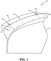
FIG. 1 is a perspective view of a fragmentary section of an airfoil constructed in accordance with the teachings of this disclosure; -
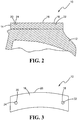
FIG. 2 is a cross-sectional view of the airfoil ofFIG. 1 taken along line 2-2 ofFIG. 1 ; and -
FIG. 3 is a top plan view of the airfoil ofFIG. 1 ; -
FIG. 4 is a cross-sectional view of an airfoil similar toFIG. 1 , including a substantially cylindrical datum point; -
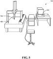
FIG. 5 is a schematic view of a coordinate measuring machine; and -
FIG. 6 is a flowchart illustrating the steps of the present disclosure. - As noted above, the disclosure pertains primarily to a method of transferring datum points from a pre-coated state of a component to a post-coated state of the component to expedite the inspection process. It is to be noted, however, that the appended drawings illustrate only typical embodiments and are therefore not to be considered limiting with respect to the scope of the disclosure or claims. Rather, the concepts of the present disclosure may apply within other equally effective embodiments. Moreover, the drawings are not necessarily to scale, emphasis generally being placed upon illustrating the principles of certain embodiments.
- Referring now to the drawings, and with specific reference to
FIG. 1 , a component manufactured in accordance with the present disclosure is generally referred to byreference numeral 10. Throughout the following disclosure reference will be made to the component as being an airfoil, such as a blade or vane of a gas turbine engine, but it is to be understood that the teachings of this disclosure can be employed with equal effect to any component needing precise measurement. Moreover, it is noted that the use of "component" and "airfoil" are interchangeable. "Airfoil" is used to denote a particular type of component and is used in order to more clearly describe the method of the present disclosure. Therefore, it is understood that the present disclosure is not limited to airfoils, but applies to all components, which generally have a pre-coated and post-coated state as will now be described. - Furthermore, throughout the disclosure reference is made to datum "points". It is to be understood that the use of "points" is to denote any general datum feature. Thus, the use of "points" is not limited to the strict definition as is generally known and is interchangeable with words such as "feature" and "line" where appropriate.
- As an example of the present invention, discussion is directed toward the manufacturing and inspecting processes of airfoils as generally used in the jet engine industry. Such airfoils are commonly manufactured from titanium metal. The strong, low-density and highly corrosion-resistant properties of titanium are ideal for use in aerospace applications. However, in an effort to improve upon the current technology and make the airfoil even lighter, the industry is moving in the direction of fabricating such airfoils from aluminum alloy.
- Unlike a titanium airfoil, an aluminum alloy airfoil requires coatings on all surfaces to protect the metal from corrosion and erosion caused by the elements. In particular, the aluminum alloy airfoil is masked and then coated with polyurethane for protection. The masking and polyurethane coating add a significant thickness to the airfoil. Moreover, coating the entire surface of the aluminum alloy airfoil covers over the planar datum points that may be originally marked on the surface of the pre-coated airfoil. This covering over of the planar datum points presents a problem when inspecting the airfoil because the planar datum points can no longer be used when inspecting the airfoil in the post-coated state. It is in this regard that the present disclosure greatly improves upon the prior art.
- Referring again to
FIG. 1 , theairfoil 10 is shown to include ablade 12, which extends longitudinally from anattachment 14, such as a dovetail attachment. Theattachment 14 has aflat surface 16 on which are provided afirst datum point 18 and asecond datum point 20. Bothdatum points Flat surface 16 may be used as a third datum point, specifically when the exact thickness of the coating is known or can be measured by other means, as described later herein. - As shown best in
FIG. 2 , in the pre-coated state, both thefirst datum point 18 and thesecond datum point 20 are designed to be substantially hemi-spherical in shape and have diameters that measure approximately 0.953 cm (0.375 inches). However, other shapes and dimensions are certainly possible. Regardless of the dimension used, what is of import is that, the first and second datum points 18,20 have a pre-determined depth dimension with respect to theflat surface 16. This inclusion of the first and second data points 18,20 onto theflat surface 16, in its pre-coated state, facilitates inspecting and correlating pre-coated dimensions to post-coated dimensions as described in more detail further below. - It is important to note that after the coating process, the first and second datum points 18,20 are not entirely filled in with coating material and thus maintain their pre-coated shape albeit with a slightly decreased diameter measurement. Because the center point of a hemi-spherical shape is independent of its diameter, the first and second datum points 18,20 have the same center points 22,24 before and after the coating process. In other words, the center points 22,24 in the pre-coated state have the same dimension as in the post-coated state even though the diameters of the first and second datum points 18,20 are changed due to the thickness of the coating. Thus, it can be seen that the design of the first and second datum points 18,20 overcome the problem of the prior art planar datum points of being coated over and unusable in the post-coated state. Furthermore, the design of these
datum points - For example, and with particular reference to
Figure 3 , the center points 22,24 of the datum points 18,20, respectively, andflat surface 16, acting as a third datum point, are used to measure theairfoil 10 in the post-coated state. Having already used the first and second datum points 18,20 and theflat surface 16 to measure theairfoil 10 in the pre-coated state, the present disclosure can now correlate the measurements ofairfoil 10 in the pre-coated and post-coated states for inspection purposes. The technique of using thesedatum points flat surface 16 are particularly useful during CMM or white light inspection because the inspection data can be taken over the entire surface of theairfoil 10, including the surfaces of the datum points 18,20, which makes it simple to find the center points 22,24. - In another aspect of the embodiment, three datum points are used in place of two
datum points flat surface 16. Because it is well known in the industry that a dimension of a desired portion on a component can be measured by using datum points as references, which locate the part in the six degrees of freedom needed to fully constrain the part, it is appreciated that the location of the three datum points may be located anywhere on the component in order to measure any desired portion on the component. Similarly, the number of datum points used may be in excess of three such as four or more. Further, the diameter of the datum points may vary in size to fit the need of the particular component being inspected. - In yet another aspect of the embodiment, as shown in
FIG. 4 , one hemi-spherical datum point, one flat surface and one substantiallycylindrical datum point 26 may be used in place of two hemi-spherical datum points and a flat surface. Thecylindrical datum point 26 includes a substantially circular shape having acenter point 28. Since thecylindrical datum point 26 maintains its shape from a pre-coated state to a post-coated state, itscenter point 28 is also the same in both states. Thus, it is appreciated that thecylindrical datum point 26 is utilized in the same manner as described above for the hemi-spherical datum points. Expounding upon this, in a further aspect of the embodiment, at least three datum points of any shape that has a center point dimension, which is the same in the pre-coated state and the post-coated state, may be used in place of two hemi-spherical datum points flat surface 16. - In operation, the present disclosure may be used to assist the inspection system of
FIG. 5 and practice of the method ofFIG. 6 .FIG. 5 illustrates a system, generally referred to byreference numeral 100, for inspecting components of a gas turbine engine. Thesystem 100 includes a measuringprobe 102 and aprocessor 104, which is operationally associated with the measuringprobe 102. Thesystem 100 also includes aplatform 106, which is operationally associated with the measuringprobe 102. Theplatform 106 is designed to receive thecomponent 10 in a manner so that the measuringprobe 102 andprocessor 104 measure the center points 22,24 of the first and second datum points 18,20 in a pre-coated state and a post-coated state. In one embodiment of thesystem 100, the measuringprobe 102 employs a white light measurement method. In another embodiment of thesystem 100, the measuringprobe 102, theprocessor 104 and theplat form 106 are part of a coordinate measuring machine (CMM). Another embodiment of thesystem 100, includes a third datum point having a substantially hemi-spherical shape and a center point. In yet another embodiment, the component further includes a flat surface serving as a third datum point. And in a further embodiment, the component is an airfoil. -
FIG. 6 illustrates aflowchart 200 of a method of inspecting components between a pre-coated state and a post-coated state.Box 202 shows the first step of providing at least first and second datum points onto the component in a pre-coated state. Each of the at least first and second datum points have a substantially hemi-spherical shape and a center point. Next, the center points of each of the at least first and second datum points are utilized for measurement of a selected portion on the component. This step is shown inbox 204.Box 206 is the step of coating the component. In the next step of the method, the center points of each of the at least first and second datum points are utilized for measurement of the selected portion on the component in the post-coated state, as shown inbox 208.Box 210 shows the final step of correlating the pre-coated state measurements and the post-coated state measurements for inspection purposes. - While the present disclosure has shown and described details of exemplary embodiments, it will be understood by one skilled in the art that various changes in detail may be effected therein without departing from the scope of the disclosure as defined by claims supported by the written description and drawings.
Claims (15)
- A method of inspecting components (10) of a gas turbine engine between a pre-coated state and a post-coated state, comprising:providing at least first and second datum points (18,20;18,26) onto the component in the pre-coated state, each of the at least first and second datum points having a substantially hemi-spherical shape and a center point (22,24;22,28);utilizing the center points (22,24;22,28) of each of the at least first and second datum points (18,20;18,26) for measurement of a selected portion on the component (10);coating the component without entirely filling in the first and second datum points (18;20;18;26);utilizing the center points (22,24;22,28) of each of the at least first and second datum points (18,20;18,26) for measurement of the selected portion on the component (10) in the post-coated state; andcorrelating the pre-coated state measurements and the post-coated state measurements for inspection purposes.
- The method of claim 1, wherein a third datum point having a substantially hemi-spherical shape and a center point is provided on the component.
- The method of claim 2, wherein each of the at least first through third datum points have a diameter of approximately 0.953 cm (0.375 inches).
- The method of claim 1, wherein a third datum point having a substantially cylindrical shape and a center point is provided on the component.
- The method of claim 1, wherein the component further includes a flat planar surface (16).
- The method of claim 5, wherein each of the at least first and second datum points (18,20;18,26) are located on the flat planar surface (16) of the component (10).
- The method of claim 1, further including a fourth datum point, which is used in conjunction with the center point of the at least first datum point and the at least third datum point, for measurement of the selected portion on the component in the pre-coated state and post-coated state.
- An airfoil (10) comprising:an attachment (14) having a flat surface (16);a blade (12) extending longitudinally from the attachment (14); andat least first and second datum points (18,20) being disposed on the flat surface (16) of the attachment (14), each of the at least first and second datum points (18,20) having a substantially hemi-spherical shape and a center point (22,24), the center points and the flat surface being configured for transferring measurements of a selected portion on the airfoil from a pre-coated state to a post-coated state, wherein the first and second datum points (18,20) are not entirely filled in during a coating of the airfoil in order to provide the post-coated state of the airfoil.
- An airfoil (10) of claim 8, further including a third datum point (16).
- An airfoil of claim 9, wherein the third datum point has a substantially hemi-spherical shape and a center point, the center point of the third datum point, in conjunction with the center points of each of the at least first and second datum points, being used for transferring measurements of the selected portion on the airfoil from the pre-coated state to the post-coated state.
- An airfoil of claim 10, wherein each of the first through third datum points have a diameter of approximately 0.953 cm (0.375 inches).
- An airfoil of claim 9, wherein the third datum point has a substantially cylindrical shape and a center point used for transferring measurements of the selected portion on the airfoil from the pre-coated state to the post-coated state.
- An airfoil (10) of claim 8, wherein the flat surface (16) is a third datum point used for transferring measurements of the selected portion on the airfoil from the pre-coated state to the post-coated state.
- An airfoil of claim 13, further including a fourth datum point used, in conjunction with the center point of each of the at least first datum point and the flat surface, for transferring measurements of the selected portion on the airfoil from the pre-coated state to the post-coated state.
- A system for inspecting components of a gas turbine engine (10), comprising:a measuring probe (102);a processor (104) operationally associated with the measuring probe (102); anda platform (106) receiving the component (10), the component including at least first and second datum points (18,20) having a substantially hemi-spherical shape and a center point (22,24), the measuring probe (102) and processor (104) for measuring the center points (22,24) of each of the at least first and second datum points (18,20) in a pre-coated state and a post-coated state, wherein the first and second datum points (18,20) are not entirely filled in during a coating of the component in order to provide the post-coated state of the component.
Applications Claiming Priority (2)
| Application Number | Priority Date | Filing Date | Title |
|---|---|---|---|
| US201361791565P | 2013-03-15 | 2013-03-15 | |
| PCT/US2013/076004 WO2014143285A1 (en) | 2013-03-15 | 2013-12-18 | Datum transfer apparatus and method for inspecting coated components |
Publications (3)
| Publication Number | Publication Date |
|---|---|
| EP2972077A1 EP2972077A1 (en) | 2016-01-20 |
| EP2972077A4 EP2972077A4 (en) | 2016-11-16 |
| EP2972077B1 true EP2972077B1 (en) | 2019-11-27 |
Family
ID=51537464
Family Applications (1)
| Application Number | Title | Priority Date | Filing Date |
|---|---|---|---|
| EP13877533.3A Active EP2972077B1 (en) | 2013-03-15 | 2013-12-18 | Datum transfer apparatus and method for inspecting coated components |
Country Status (3)
| Country | Link |
|---|---|
| US (1) | US9927220B2 (en) |
| EP (1) | EP2972077B1 (en) |
| WO (1) | WO2014143285A1 (en) |
Families Citing this family (1)
| Publication number | Priority date | Publication date | Assignee | Title |
|---|---|---|---|---|
| EP2610577B1 (en) * | 2011-12-30 | 2018-01-24 | Hexagon Metrology S.p.A. | Process for producing a beam element of a co-ordinate measuring machine, and measuring machine provided with said beam element |
Family Cites Families (14)
| Publication number | Priority date | Publication date | Assignee | Title |
|---|---|---|---|---|
| JPH01277705A (en) | 1988-04-30 | 1989-11-08 | Mazda Motor Corp | Method and apparatus for detecting reference position |
| JPH0785995B2 (en) | 1988-07-15 | 1995-09-20 | 三菱自動車工業株式会社 | How to control car body assembly accuracy by laser marks |
| JPH0785995A (en) | 1993-09-20 | 1995-03-31 | Hitachi Ltd | Plasma generation method and apparatus |
| US6416278B1 (en) * | 2000-11-16 | 2002-07-09 | General Electric Company | Turbine nozzle segment and method of repairing same |
| US6570175B2 (en) | 2001-11-01 | 2003-05-27 | Computerized Thermal Imaging, Inc. | Infrared imaging arrangement for turbine component inspection system |
| US7351290B2 (en) * | 2003-07-17 | 2008-04-01 | General Electric Company | Robotic pen |
| EP1643209B1 (en) * | 2004-09-30 | 2020-11-04 | Ansaldo Energia IP UK Limited | Method for measuring a coating thickness |
| US7333218B2 (en) | 2005-06-28 | 2008-02-19 | United Technologies Corporation | Systems and methods for determining the location and angular orientation of a hole with an obstructed opening residing on a surface of an article |
| US20060291716A1 (en) * | 2005-06-28 | 2006-12-28 | Janakiraman Vaidyanathan | Thermal imaging and laser scanning systems and methods for determining the location and angular orientation of a hole with an obstructed opening residing on a surface of an article |
| EP1767743A1 (en) * | 2005-09-26 | 2007-03-28 | Siemens Aktiengesellschaft | Method to produce a coated gas turbine component having opening holes, apparatus to perform the method and coated turbine blade having cooling holes |
| DE102006016703A1 (en) * | 2006-04-08 | 2007-10-11 | Mtu Aero Engines Gmbh | Method of repairing a vane segment |
| EP2386823A1 (en) * | 2010-05-12 | 2011-11-16 | Siemens Aktiengesellschaft | Surface analysis and device for detecting closed holes and device for opening them again |
| JP5686279B2 (en) | 2010-09-16 | 2015-03-18 | いすゞ自動車株式会社 | Work posture detection device, work processing execution device, and work posture detection method |
| ES2992591T3 (en) | 2015-08-18 | 2024-12-16 | Rakuten Medical Inc | Compositions, combinations and related methods for photoimmunotherapy |
-
2013
- 2013-12-18 WO PCT/US2013/076004 patent/WO2014143285A1/en not_active Ceased
- 2013-12-18 EP EP13877533.3A patent/EP2972077B1/en active Active
- 2013-12-18 US US14/767,864 patent/US9927220B2/en active Active
Non-Patent Citations (1)
| Title |
|---|
| None * |
Also Published As
| Publication number | Publication date |
|---|---|
| WO2014143285A1 (en) | 2014-09-18 |
| EP2972077A4 (en) | 2016-11-16 |
| EP2972077A1 (en) | 2016-01-20 |
| US20150369582A1 (en) | 2015-12-24 |
| US9927220B2 (en) | 2018-03-27 |
Similar Documents
| Publication | Publication Date | Title |
|---|---|---|
| ES2799879T3 (en) | Automated rivet measurement system | |
| JP6838836B2 (en) | Identification systems and methods for components | |
| US20160243663A1 (en) | Processing inspection workpiece for machine tool, and on-machine measurement method using said workpiece | |
| JP2015093346A5 (en) | On-machine measuring method using machining inspection work of machine tool | |
| KR20170103625A (en) | Test system and method for examining a hollow body | |
| US20070019213A1 (en) | Systems and methods for determining the location and angular orientation of a hole with an obstructed opening residing on a surface of an article | |
| Cuesta et al. | A new concept of feature-based gauge for coordinate measuring arm evaluation | |
| JP6591551B2 (en) | Method and coating system for coating cavity walls | |
| US11493413B2 (en) | Testing method and test piece of thermal barrier coating | |
| US9927220B2 (en) | Datum transfer apparatus and method for inspecting coated components | |
| JP6469927B1 (en) | Inspection master | |
| KR20140050336A (en) | Correction method for center of shaft tube | |
| US10018458B2 (en) | Validating parts using a number of contiguous coupons produced from part excess | |
| CN113028954B (en) | Verticality detection device and detection method of the pressure bottom hole of the wind tunnel pressure test model | |
| Wang et al. | A measurement method for the axial bending deformation of parts with circumferential cycling element based on laser profile sensor | |
| CN118896548A (en) | A measurement accuracy evaluation method and system for pipeline online detection equipment | |
| US20250067614A1 (en) | Balance inspection apparatus, balance inspection method, balance-inspected crankshaft, arithmetic processing device, and program | |
| US11143620B2 (en) | Electromagnetic probe testing of bond coat | |
| CN117091468A (en) | CRH5 high-speed EMU gear cylindrical bearing cover three-dimensional processing and inspection combined tooling | |
| Moravčíková et al. | The influence of machine-part measuring strategies for coordinate measuring devices on the precision of the measured values | |
| KR102379294B1 (en) | A method for examining external diameter of tapered shaft using a micrometer | |
| El Asmai et al. | Improvement of segmented bars for the verification of coordinate measuring arms | |
| Florussen et al. | Assessing the accuracy of five axis machines by comparing machine measurement data with test work piece deviations | |
| Kuczmaszewski et al. | Comparative analysis of the measurement accuracy of geometric features of aircraft components measured by 3D digitisation system and coordinate measuring technique | |
| CN114485330B (en) | Measuring tools and measuring methods |
Legal Events
| Date | Code | Title | Description |
|---|---|---|---|
| PUAI | Public reference made under article 153(3) epc to a published international application that has entered the european phase |
Free format text: ORIGINAL CODE: 0009012 |
|
| 17P | Request for examination filed |
Effective date: 20150924 |
|
| AK | Designated contracting states |
Kind code of ref document: A1 Designated state(s): AL AT BE BG CH CY CZ DE DK EE ES FI FR GB GR HR HU IE IS IT LI LT LU LV MC MK MT NL NO PL PT RO RS SE SI SK SM TR |
|
| AX | Request for extension of the european patent |
Extension state: BA ME |
|
| DAX | Request for extension of the european patent (deleted) | ||
| REG | Reference to a national code |
Ref country code: DE Ref legal event code: R079 Ref document number: 602013063477 Country of ref document: DE Free format text: PREVIOUS MAIN CLASS: G01B0021040000 Ipc: G01B0005008000 |
|
| RAP1 | Party data changed (applicant data changed or rights of an application transferred) |
Owner name: UNITED TECHNOLOGIES CORPORATION |
|
| A4 | Supplementary search report drawn up and despatched |
Effective date: 20161019 |
|
| RIC1 | Information provided on ipc code assigned before grant |
Ipc: F01D 5/28 20060101ALI20161013BHEP Ipc: G01B 11/03 20060101ALI20161013BHEP Ipc: F01D 5/14 20060101ALI20161013BHEP Ipc: F01D 21/00 20060101ALI20161013BHEP Ipc: G01M 13/00 20060101ALI20161013BHEP Ipc: G01B 13/00 20060101ALI20161013BHEP Ipc: G01B 5/008 20060101AFI20161013BHEP |
|
| GRAP | Despatch of communication of intention to grant a patent |
Free format text: ORIGINAL CODE: EPIDOSNIGR1 |
|
| STAA | Information on the status of an ep patent application or granted ep patent |
Free format text: STATUS: GRANT OF PATENT IS INTENDED |
|
| INTG | Intention to grant announced |
Effective date: 20190607 |
|
| GRAS | Grant fee paid |
Free format text: ORIGINAL CODE: EPIDOSNIGR3 |
|
| GRAA | (expected) grant |
Free format text: ORIGINAL CODE: 0009210 |
|
| STAA | Information on the status of an ep patent application or granted ep patent |
Free format text: STATUS: THE PATENT HAS BEEN GRANTED |
|
| AK | Designated contracting states |
Kind code of ref document: B1 Designated state(s): AL AT BE BG CH CY CZ DE DK EE ES FI FR GB GR HR HU IE IS IT LI LT LU LV MC MK MT NL NO PL PT RO RS SE SI SK SM TR |
|
| REG | Reference to a national code |
Ref country code: GB Ref legal event code: FG4D |
|
| REG | Reference to a national code |
Ref country code: CH Ref legal event code: EP |
|
| REG | Reference to a national code |
Ref country code: AT Ref legal event code: REF Ref document number: 1207162 Country of ref document: AT Kind code of ref document: T Effective date: 20191215 |
|
| REG | Reference to a national code |
Ref country code: DE Ref legal event code: R096 Ref document number: 602013063477 Country of ref document: DE |
|
| REG | Reference to a national code |
Ref country code: IE Ref legal event code: FG4D |
|
| REG | Reference to a national code |
Ref country code: NL Ref legal event code: MP Effective date: 20191127 |
|
| REG | Reference to a national code |
Ref country code: LT Ref legal event code: MG4D |
|
| PG25 | Lapsed in a contracting state [announced via postgrant information from national office to epo] |
Ref country code: NL Free format text: LAPSE BECAUSE OF FAILURE TO SUBMIT A TRANSLATION OF THE DESCRIPTION OR TO PAY THE FEE WITHIN THE PRESCRIBED TIME-LIMIT Effective date: 20191127 Ref country code: GR Free format text: LAPSE BECAUSE OF FAILURE TO SUBMIT A TRANSLATION OF THE DESCRIPTION OR TO PAY THE FEE WITHIN THE PRESCRIBED TIME-LIMIT Effective date: 20200228 Ref country code: LT Free format text: LAPSE BECAUSE OF FAILURE TO SUBMIT A TRANSLATION OF THE DESCRIPTION OR TO PAY THE FEE WITHIN THE PRESCRIBED TIME-LIMIT Effective date: 20191127 Ref country code: NO Free format text: LAPSE BECAUSE OF FAILURE TO SUBMIT A TRANSLATION OF THE DESCRIPTION OR TO PAY THE FEE WITHIN THE PRESCRIBED TIME-LIMIT Effective date: 20200227 Ref country code: FI Free format text: LAPSE BECAUSE OF FAILURE TO SUBMIT A TRANSLATION OF THE DESCRIPTION OR TO PAY THE FEE WITHIN THE PRESCRIBED TIME-LIMIT Effective date: 20191127 Ref country code: BG Free format text: LAPSE BECAUSE OF FAILURE TO SUBMIT A TRANSLATION OF THE DESCRIPTION OR TO PAY THE FEE WITHIN THE PRESCRIBED TIME-LIMIT Effective date: 20200227 Ref country code: LV Free format text: LAPSE BECAUSE OF FAILURE TO SUBMIT A TRANSLATION OF THE DESCRIPTION OR TO PAY THE FEE WITHIN THE PRESCRIBED TIME-LIMIT Effective date: 20191127 Ref country code: SE Free format text: LAPSE BECAUSE OF FAILURE TO SUBMIT A TRANSLATION OF THE DESCRIPTION OR TO PAY THE FEE WITHIN THE PRESCRIBED TIME-LIMIT Effective date: 20191127 |
|
| PG25 | Lapsed in a contracting state [announced via postgrant information from national office to epo] |
Ref country code: HR Free format text: LAPSE BECAUSE OF FAILURE TO SUBMIT A TRANSLATION OF THE DESCRIPTION OR TO PAY THE FEE WITHIN THE PRESCRIBED TIME-LIMIT Effective date: 20191127 Ref country code: IS Free format text: LAPSE BECAUSE OF FAILURE TO SUBMIT A TRANSLATION OF THE DESCRIPTION OR TO PAY THE FEE WITHIN THE PRESCRIBED TIME-LIMIT Effective date: 20200327 Ref country code: RS Free format text: LAPSE BECAUSE OF FAILURE TO SUBMIT A TRANSLATION OF THE DESCRIPTION OR TO PAY THE FEE WITHIN THE PRESCRIBED TIME-LIMIT Effective date: 20191127 |
|
| PG25 | Lapsed in a contracting state [announced via postgrant information from national office to epo] |
Ref country code: AL Free format text: LAPSE BECAUSE OF FAILURE TO SUBMIT A TRANSLATION OF THE DESCRIPTION OR TO PAY THE FEE WITHIN THE PRESCRIBED TIME-LIMIT Effective date: 20191127 |
|
| PG25 | Lapsed in a contracting state [announced via postgrant information from national office to epo] |
Ref country code: DK Free format text: LAPSE BECAUSE OF FAILURE TO SUBMIT A TRANSLATION OF THE DESCRIPTION OR TO PAY THE FEE WITHIN THE PRESCRIBED TIME-LIMIT Effective date: 20191127 Ref country code: CZ Free format text: LAPSE BECAUSE OF FAILURE TO SUBMIT A TRANSLATION OF THE DESCRIPTION OR TO PAY THE FEE WITHIN THE PRESCRIBED TIME-LIMIT Effective date: 20191127 Ref country code: ES Free format text: LAPSE BECAUSE OF FAILURE TO SUBMIT A TRANSLATION OF THE DESCRIPTION OR TO PAY THE FEE WITHIN THE PRESCRIBED TIME-LIMIT Effective date: 20191127 Ref country code: EE Free format text: LAPSE BECAUSE OF FAILURE TO SUBMIT A TRANSLATION OF THE DESCRIPTION OR TO PAY THE FEE WITHIN THE PRESCRIBED TIME-LIMIT Effective date: 20191127 Ref country code: PT Free format text: LAPSE BECAUSE OF FAILURE TO SUBMIT A TRANSLATION OF THE DESCRIPTION OR TO PAY THE FEE WITHIN THE PRESCRIBED TIME-LIMIT Effective date: 20200419 Ref country code: RO Free format text: LAPSE BECAUSE OF FAILURE TO SUBMIT A TRANSLATION OF THE DESCRIPTION OR TO PAY THE FEE WITHIN THE PRESCRIBED TIME-LIMIT Effective date: 20191127 |
|
| REG | Reference to a national code |
Ref country code: CH Ref legal event code: PL |
|
| REG | Reference to a national code |
Ref country code: BE Ref legal event code: MM Effective date: 20191231 |
|
| REG | Reference to a national code |
Ref country code: DE Ref legal event code: R097 Ref document number: 602013063477 Country of ref document: DE |
|
| PG25 | Lapsed in a contracting state [announced via postgrant information from national office to epo] |
Ref country code: MC Free format text: LAPSE BECAUSE OF FAILURE TO SUBMIT A TRANSLATION OF THE DESCRIPTION OR TO PAY THE FEE WITHIN THE PRESCRIBED TIME-LIMIT Effective date: 20191127 Ref country code: SM Free format text: LAPSE BECAUSE OF FAILURE TO SUBMIT A TRANSLATION OF THE DESCRIPTION OR TO PAY THE FEE WITHIN THE PRESCRIBED TIME-LIMIT Effective date: 20191127 Ref country code: SK Free format text: LAPSE BECAUSE OF FAILURE TO SUBMIT A TRANSLATION OF THE DESCRIPTION OR TO PAY THE FEE WITHIN THE PRESCRIBED TIME-LIMIT Effective date: 20191127 |
|
| REG | Reference to a national code |
Ref country code: AT Ref legal event code: MK05 Ref document number: 1207162 Country of ref document: AT Kind code of ref document: T Effective date: 20191127 |
|
| PLBE | No opposition filed within time limit |
Free format text: ORIGINAL CODE: 0009261 |
|
| STAA | Information on the status of an ep patent application or granted ep patent |
Free format text: STATUS: NO OPPOSITION FILED WITHIN TIME LIMIT |
|
| PG25 | Lapsed in a contracting state [announced via postgrant information from national office to epo] |
Ref country code: LU Free format text: LAPSE BECAUSE OF NON-PAYMENT OF DUE FEES Effective date: 20191218 Ref country code: IE Free format text: LAPSE BECAUSE OF NON-PAYMENT OF DUE FEES Effective date: 20191218 |
|
| 26N | No opposition filed |
Effective date: 20200828 |
|
| PG25 | Lapsed in a contracting state [announced via postgrant information from national office to epo] |
Ref country code: CH Free format text: LAPSE BECAUSE OF NON-PAYMENT OF DUE FEES Effective date: 20191231 Ref country code: LI Free format text: LAPSE BECAUSE OF NON-PAYMENT OF DUE FEES Effective date: 20191231 Ref country code: PL Free format text: LAPSE BECAUSE OF FAILURE TO SUBMIT A TRANSLATION OF THE DESCRIPTION OR TO PAY THE FEE WITHIN THE PRESCRIBED TIME-LIMIT Effective date: 20191127 Ref country code: AT Free format text: LAPSE BECAUSE OF FAILURE TO SUBMIT A TRANSLATION OF THE DESCRIPTION OR TO PAY THE FEE WITHIN THE PRESCRIBED TIME-LIMIT Effective date: 20191127 Ref country code: BE Free format text: LAPSE BECAUSE OF NON-PAYMENT OF DUE FEES Effective date: 20191231 Ref country code: SI Free format text: LAPSE BECAUSE OF FAILURE TO SUBMIT A TRANSLATION OF THE DESCRIPTION OR TO PAY THE FEE WITHIN THE PRESCRIBED TIME-LIMIT Effective date: 20191127 |
|
| PG25 | Lapsed in a contracting state [announced via postgrant information from national office to epo] |
Ref country code: IT Free format text: LAPSE BECAUSE OF FAILURE TO SUBMIT A TRANSLATION OF THE DESCRIPTION OR TO PAY THE FEE WITHIN THE PRESCRIBED TIME-LIMIT Effective date: 20191127 |
|
| PG25 | Lapsed in a contracting state [announced via postgrant information from national office to epo] |
Ref country code: CY Free format text: LAPSE BECAUSE OF FAILURE TO SUBMIT A TRANSLATION OF THE DESCRIPTION OR TO PAY THE FEE WITHIN THE PRESCRIBED TIME-LIMIT Effective date: 20191127 |
|
| PG25 | Lapsed in a contracting state [announced via postgrant information from national office to epo] |
Ref country code: HU Free format text: LAPSE BECAUSE OF FAILURE TO SUBMIT A TRANSLATION OF THE DESCRIPTION OR TO PAY THE FEE WITHIN THE PRESCRIBED TIME-LIMIT; INVALID AB INITIO Effective date: 20131218 Ref country code: MT Free format text: LAPSE BECAUSE OF FAILURE TO SUBMIT A TRANSLATION OF THE DESCRIPTION OR TO PAY THE FEE WITHIN THE PRESCRIBED TIME-LIMIT Effective date: 20191127 |
|
| PG25 | Lapsed in a contracting state [announced via postgrant information from national office to epo] |
Ref country code: TR Free format text: LAPSE BECAUSE OF FAILURE TO SUBMIT A TRANSLATION OF THE DESCRIPTION OR TO PAY THE FEE WITHIN THE PRESCRIBED TIME-LIMIT Effective date: 20191127 |
|
| PG25 | Lapsed in a contracting state [announced via postgrant information from national office to epo] |
Ref country code: MK Free format text: LAPSE BECAUSE OF FAILURE TO SUBMIT A TRANSLATION OF THE DESCRIPTION OR TO PAY THE FEE WITHIN THE PRESCRIBED TIME-LIMIT Effective date: 20191127 |
|
| REG | Reference to a national code |
Ref country code: DE Ref legal event code: R081 Ref document number: 602013063477 Country of ref document: DE Owner name: RAYTHEON TECHNOLOGIES CORPORATION (N.D.GES.D.S, US Free format text: FORMER OWNER: UNITED TECHNOLOGIES CORPORATION, FARMINGTON, CONN., US Ref country code: DE Ref legal event code: R081 Ref document number: 602013063477 Country of ref document: DE Owner name: RTX CORPORATION (N.D.GES.D. STAATES DELAWARE),, US Free format text: FORMER OWNER: UNITED TECHNOLOGIES CORPORATION, FARMINGTON, CONN., US |
|
| P01 | Opt-out of the competence of the unified patent court (upc) registered |
Effective date: 20230520 |
|
| REG | Reference to a national code |
Ref country code: DE Ref legal event code: R081 Ref document number: 602013063477 Country of ref document: DE Owner name: RTX CORPORATION (N.D.GES.D. STAATES DELAWARE),, US Free format text: FORMER OWNER: RAYTHEON TECHNOLOGIES CORPORATION (N.D.GES.D.STAATES DELAWARE), ARLINGTON, VA, US |
|
| PGFP | Annual fee paid to national office [announced via postgrant information from national office to epo] |
Ref country code: DE Payment date: 20251126 Year of fee payment: 13 |
|
| PGFP | Annual fee paid to national office [announced via postgrant information from national office to epo] |
Ref country code: GB Payment date: 20251120 Year of fee payment: 13 |
|
| PGFP | Annual fee paid to national office [announced via postgrant information from national office to epo] |
Ref country code: FR Payment date: 20251120 Year of fee payment: 13 |